

Page 1

JetFusion
Integrated Access Device
User’s Guide
Document No. 2000-A2-GB20-10
February 2004
Page 2

Copyright © 2004 Paradyne Corporation.
All rights reserved.
Printed in U.S.A.
Notice
This publication is protected by federal copyright law. No part of this publication may be copied or distributed,
transmitted, transcribed, stored in a retrieval system, or translated into any human or computer language in any form or
by any means, electronic, mechanical, magnetic, manual or otherwise, or disclosed to third parties without the express
written permission of Paradyne Corporation, 8545 126th Ave. N., Largo, FL 33773.
Paradyne Corporation makes no representation or warranties with respect to the contents hereof and specifically
disclaims any implied warranties of merchantability or fitness for a particular purpose. Further, Paradyne Corporation
reserves the right to revise this publication and to make changes from time to time in the contents hereof without
obligation of Paradyne Corporation to notify any person of such revision or changes.
Changes and enhancements to the product and to the information herein will be documented and issued as a new
release to this manual.
Warranty, Sales, Service, and Training Information
Contact your local sales representative, service representative, or distributor directly for any help needed. For
additional information concerning warranty, sales, service, repair, installation, documentation, training, distributor
locations, or Paradyne worldwide office locations, use one of the following methods:
Internet: Visit the Paradyne World Wide Web site at www.paradyne.com. (Be sure to register your warranty at
www.paradyne.com/warranty.)
Telephone: Call our automated system to receive current information by fax or to speak with a company
representative.
— Within the U.S.A., call 1-800-870-2221
— Outside the U.S.A., call 1-727-530-2340
Document Feedback
We welcome your comments and suggestions about this document. Please mail them to Technical Publications,
Paradyne Corporation, 8545 126th Ave. N., Largo, FL 33773, or send e-mail to userdoc@paradyne.com. Include the
number and title of this document in your correspondence. Please include your name and phone number if you are
willing to provide additional clarification.
Trade mar ks
ACCULINK, COMSPHERE, ETC, EtherLoop, FrameSaver, GranDSLAM, Hotwire, the Hotwire logo, Jetstream, MVL,
NextEDGE, OpenLane, Paradyne, the Paradyne logo, Paradyne Credit Corp., the Paradyne Credit Corp. logo,
Performance Wizard, StormPort, and TruePut are all registered trademarks of Paradyne Corporation. ADSL/R,
BitStorm, Connect to Success, GrandVIEW, Hotwire Connected, iMarc, JetFusion, JetVision, MicroBurst,
PacketSurfer, ReachDSL, Spectrum Manager, StormTracker, and TriplePlay are trademarks of Paradyne Corporation.
All other products and services mentioned herein are the trademarks, service marks, registered trademarks, or
registered service marks of their respective owners.
2000-A2-GB20-10 - A - February 2004
Page 3

7DEOHRI&RQWHQWV
Preface
Audience.................................................................................. xi
Contents .................................................................................. xi
Safeguards ..............................................................................xii
Product Warranty....................................................................xiii
Conventions............................................................................xiii
Regulatory Notices .................................................................xiii
Chapter 1 Introduction
Data Interfaces .........................................................................2
JetFusion 2/4/8-Port IAD Family...............................................2
Front Panel Power and Status Indicators............................3
Rear Panel Connectors.......................................................4
JetFusion 16/24-Port IAD Family..............................................4
Front Panel Power and Status Indicators............................5
Rear Panel Connectors.......................................................6
Chapter 2 Quick Start Guide
Unpacking the IAD....................................................................9
Installing the IAD ......................................................................9
Connect via Terminal Emulator...............................................10
Setting the Ethernet Port IP Address ................................12
Resetting the IAD ...................................................................14
Connecting via Telnet .............................................................15
Running Telnet ..................................................................15
Using the Menu Interface .......................................................16
2000-A2-GB20-10 - i - February 2004
Page 4

Basic IAD Configur-ation ........................................................19
Connecting LAN, WAN, USI and Telephones.........................19
Ethernet LAN Connection .................................................19
WAN Connections.............................................................19
USI Connection (16/24-Port) ............................................20
Telephone Connections.....................................................20
Confirming Proper Setup........................................................21
Chapter 3 Administration
IAD Security............................................................................23
RADIUS Server Settings ........................................................26
Setting Up SNMP ...................................................................28
Using the SNMP Configuration Menu ...............................28
Upgrading the System............................................................32
Setting up Your LAN Connection............................................34
Using System Utilities.............................................................35
Managing Configuration Files ...........................................37
Using the File System.............................................................39
Using the Debug Menu...........................................................41
Performing File Transfers.......................................................43
Using File Transfer Utilities ...............................................44
Setting Derived Timing Options ..............................................46
Verifying an IP Address ..........................................................47
Verifying an IP Address for Windows Systems .................47
Verifying the IAD IP Addresses.........................................47
Chapter 4 WAN Configuration
Basic WAN Setup Tasks.........................................................48
Using the WAN Configuration Menu.......................................52
Selecting the Datalink Protocol...............................................53
Setting Up TDM Voice ............................................................54
Selecting the Physical Interface .............................................55
2000-A2-GB20-10 - ii - February 2004
Page 5

Configuring the G.SHDSL Interface........................................56
Configuring the SDSL Interface—JF2100 ..............................59
Configuring the SDSL Interface..............................................60
Configuring the ADSL Interface..............................................64
Setting the Interface to T1 or E1.............................................65
Configuring the T1 Interface...................................................66
Configuring the E1 Interface...................................................71
Configuring ATM PVCs...........................................................75
Adding a PVC....................................................................75
Modifying a PVC ...............................................................78
Deleting a PVC..................................................................83
Showing Current PVCs .....................................................84
Configuring
ATM Options .....................................................................84
Configuring
Frame Relay DLCIs...........................................................86
Modifying a DLCI...............................................................87
Adding a DLCI...................................................................88
Deleting a DLCI.................................................................90
Displaying Current DLCIs..................................................90
Configuring
Frame Relay Options ........................................................90
Quick Configuration................................................................95
Chapter 5 Router Configuration
Basic Router Setup Tasks ......................................................97
Router Configuration Menu ....................................................98
Configuring
a Port IP Address..............................................................98
Unconfiguring a Port IP Address..........................................100
Setting the Port Maximum Transmission Unit ......................101
Enabling and Disabling RIP..................................................101
Enabling and Disabling RIP Poisoned Reverse by Port.. 101
Setting the RIP Version ...................................................102
2000-A2-GB20-10 - iii - February 2004
Page 6

Managing Static and Default Routes ....................................103
Setting the Default Route .....................................................105
Configuring DNS Client ........................................................106
Configuring DHCP Client......................................................107
Configuring DHCP Relay......................................................108
Configuring the Telnet Server Port .......................................109
Configuring IP Filtering.........................................................109
Configuring IP Header Compression (IPHC)........................ 116
Configuring the LAN IP Broadcast Destination..................... 116
Displaying the Route Table................................................... 116
Chapter 6 Bridge Configuration
Basic Bridge Setup Tasks..................................................... 119
Bridge Configuration Menu...................................................120
Enabling and Disabling Bridging...........................................120
IP Over Bridging..............................................................120
Enabling or Disabling Bridging Globally ..........................121
Enabling or Disabling Bridging by Port............................121
Setting the Bridge Aging Timer.............................................122
Enabling and Disabling STP.................................................123
Enabling or Disabling STP Globally ................................123
Enabling or Disabling STP by Port..................................123
Configuring Spanning Tree Bridge Priority ...........................124
Configuring Spanning Tree Port Priority...............................124
Configuring Spanning Tree Hello Time.................................125
Configuring Spanning Tree Maximum Age ...........................125
Configuring Spanning Tree Forward Delay ..........................125
Configuring Spanning Tree Path Cost..................................125
Deleting a Bridge Forwarding Database Entry .....................126
Chapter 7 Voice Path Configuration
Basic Voice Path Setup Tasks..............................................127
2000-A2-GB20-10 - iv - February 2004
Page 7

Voice Path Configuration Menu............................................128
Setting the Voice Gateway ...................................................128
Setting Jitter Delay ...............................................................130
Displaying Jitter Delay..........................................................130
Setting Start Mode................................................................130
Setting SLIC Control Mode...................................................132
Setting Compander Mode.....................................................132
Set On Hook Transmission Mode.........................................133
Setting Idle Voltage Mode.....................................................133
Setting Debug Mode.............................................................134
Configuring Echo Cancellation.............................................134
Setting Loop Gain.................................................................135
Setting Country Mode...........................................................137
Managing MGCP Embedded Client .....................................138
Managing Copper-Com Call Control ....................................142
JetStream Call Control Settings............................................144
Configuring AAL2/LES CAS .................................................146
Configuring for AAL2/LES CAS.......................................146
Configuring AAL2/LES CCS-ELCP ......................................150
Chapter 8 Firewall Configuration
Creating a Firewall via IP Filtering........................................154
Chapter 9 DHCP Server Configuration
Basic DHCP Server Setup Tasks .........................................155
The DHCP Server Configur-ation Menu...............................156
Using DHCP Debugging Messages .....................................156
Enabling and Disabling DHCP Server..................................156
Enabling and Disabling Checking for Additional DHCP Servers157
Configuring DHCP Server Parameters.................................157
Configuring
the DHCP Address Range Pool......................................158
2000-A2-GB20-10 - v - February 2004
Page 8

Configuring a DHCP Client Entry .........................................158
Displaying DHCP Server Details ..........................................160
Displaying DHCP Server Statistics.......................................161
Displaying DHCP Server Assigned and Unassigned Addresses161
Displaying DHCP Entry Details ............................................162
Deleting a DHCP Client Entry...............................................162
Deleting a DHCP Assign-ment Entry....................................162
Chapter 10 Multicast Configuration
Configuring Multicast............................................................163
Enabling and Disabling Global IP Multicast..........................164
Configuring PIM—Dense Mode by Port ...............................164
Managing Multicast Route Source........................................165
Adding a Multicast Routing Source ......................................165
Removing a Multicast Routing Source .................................166
Displaying the Multicast Routing Source..............................166
Displaying the IGMP Group..................................................166
Displaying the IGMP Querier................................................167
Displaying the Multicast Routing Table.................................167
Displaying the PIM Neighbor................................................168
Chapter 11 NAT Configuration
The NAT Configuration
Menu ...............................................................................170
Enabling NAT Translation.....................................................171
Configuring
NAT Local Server ............................................................172
Configuring
NAT Timeouts..................................................................173
Configuring
the NAT Port Range ........................................................174
Configuring
the NAT Alias Entry .........................................................175
NAT Statistics .......................................................................176
2000-A2-GB20-10 - vi - February 2004
Page 9

NAT Connection Table..........................................................177
NAT Connection Details .......................................................177
NAT Local Server Table........................................................179
NAT Alias Table ....................................................................179
Deleting IP Addresses from NAT Tables ..............................179
Deleting a NAT Local Server Entry.......................................180
Deleting a NAT Alias Entry ...................................................180
Chapter 12 IAD Reports
The Report Menu..................................................................181
Current Configur-ation Report ..............................................182
Network Statistics Reports....................................................184
Interface Statistics Reports...................................................193
Media Statistics Reports .......................................................205
Route Table Report...............................................................217
ARP Table Report.................................................................217
Bridge Forwarding Database Report ....................................217
Bridge Status Report ............................................................218
PPP Authorization Entries Report ........................................218
System Uptime Report .........................................................219
Memory Statistics Reports....................................................219
Zero All Statistics..................................................................220
Chapter 13 Command Line Interface
Intro-duction..........................................................................221
set wan stp bridge ................................................................221
Command Line Interface Reference.....................................223
exit........................................................................................223
ping.......................................................................................223
quit........................................................................................223
rename file............................................................................223
reset system .........................................................................224
2000-A2-GB20-10 - vii - February 2004
Page 10

remove lan ip address ..........................................................224
set bridge global ...................................................................224
set bridge stp global .............................................................225
set dhcp server enable .........................................................225
set dhcp server gateway.......................................................225
set dhcp server subnet .........................................................225
set dhcp server dns ..............................................................225
set dhcp server netbios ........................................................225
set dhcp server domain ........................................................225
set dhcp server range...........................................................226
set dns server address .........................................................226
set ip default route................................................................226
set ip route............................................................................226
set lan bridge........................................................................227
set lan ip address .................................................................227
set lan rip..............................................................................228
set lan stp bridge ..................................................................228
set mgcp bracketing .............................................................228
set mgcp listening port..........................................................228
set mgcp notified entity.........................................................229
set mgcp signaling connection .............................................229
set mgcp signaling port.........................................................229
set mgcp signaling tos..........................................................229
set mgcp voice connection ...................................................229
set mgcp voice tos................................................................230
set nat...................................................................................230
set sdsl speed.......................................................................231
set system defaults...............................................................231
set wan atm ppp auth...........................................................231
set wan atm vc......................................................................232
set wan bridge ......................................................................232
set wan datalink....................................................................233
set wan framerelay ...............................................................233
2000-A2-GB20-10 - viii - February 2004
Page 11

set wan ip address................................................................234
set wan stp bridge ................................................................234
set wan rip ............................................................................235
show configuration................................................................235
show dhcp server configuration............................................235
show ip routes ......................................................................235
tftp receive............................................................................235
Chapter 14 Troubleshooting and Diagnostics
Using the Diagnostics
Menu ...............................................................................237
POTS Diagnostics ................................................................237
SDSL Diagnostics.................................................................242
ISDN-BRI Diagnostics ..........................................................243
Troubleshooting the IAD.......................................................244
Chapter 15 Verification
Power-up Test.......................................................................247
Operational Test ...................................................................247
Maintenance.........................................................................248
Displaying the Current Configuration....................................248
Appendix A Menu Map
Menu Map.............................................................................250
Appendix B Country Codes
Country Codes Tables ..........................................................252
Appendix C JetFusion IAD Specifications
Equipment List......................................................................254
2/4/8-Port..............................................................................255
2000-A2-GB20-10 - ix - February 2004
Page 12

16/24-Port.............................................................................262
Appendix D Connector Pinouts
Connector Pinouts................................................................265
Appendix E Glossary
Glossary ...............................................................................268
Index
2000-A2-GB20-10 - x - February 2004
Page 13

3UHIDFH
The JetFusion Family IAD User Guide contains the information you need
to install, connect and configure each JetFusion IAD in a customer’s
premises.
Audience This guide is intended for network engineers and other professionals in the
telecommunications industry who are engaged in the installation,
configuration, management and support of telephone and computer
networks, network access products, and related equipment.
Contents The guide contains the following chapters and appendixes:
This preface describes the audience, how this guide is organized,
safeguards you should always observe, and warranty and regulatory
notices.
Chapter 1, Introduction on page 1, introduces the features of the IADs,
including the hardware, indicators and ports.
Chapter 2, Quick Start Guide on page 8, describes the process of getting
an IAD up and running in a typical customer premises. This chapter is
helpful if you are new to IADs, because it lists each step, beginning with
unpacking the IAD. It also provides information about logging on, using the
menu interface, setting the IP address, basic configuration tasks and
restarting the IAD. Once you have read this chapter, you will be wellprepared to use the remaining reference chapters.
Chapter 3, Administration on page 22, provides information about IAD
security, configuring Simple Network Management Protocol (SNMP),
upgrading ACOS, system utilities and other topics.
Chapter 4, WAN Configuration on page 48, details how to configure the
JetFusion IAD for physical connection to the network—T1/E1 and xDSL,
Frame Relay and ATM, and TDM Voice for channelized T1 circuits.
Chapter 5, Router Configuration on page 96 describes the steps to
configure the IAD as a router, including setting IP addresses, static routes,
configuring RIP, DNS Client, DHCP Client and other router settings.
Chapter 6, Bridge Configuration on page 118 , provides details about
setting up the IAD as a bridge, including setting bridging globally or by
port, setting the aging timer, and enabling Spanning Tree support.
Chapter 7, Voice Path Configuration on page 127, describes how to set up
voice ports for use in various DSLAM and voice gateway environments.
2000-A2-GB20-10 - xi - February 2004
Page 14

Chapter 8, Firewall Configuration on page 154, provides information about
setting up the IAD to perform IP filtering.
Chapter 9, DHCP Server Configuration on page 155, walks you through
the steps required to configure the Dynamic Host Configuration Protocol
(DHCP) server and client.
Chapter 10, Multicast Configuration on page 163, describes the steps to
configure the IAD to perform Network Address Translation (NAT).
Chapter 11, NAT Configuration on page 169, describes the steps required
to configure the IAD to perform Network Address Translation (NAT).
Chapter 12, IAD Reports on page 181, describes each report you can run.
Chapter 13, Command Line Interface on page 221, describes how to enter
and exit CLI mode, and how to use each command in the command line
interface. You may use these commands instead of using the
corresponding commands in the menu interface.
Chapter 14, Troubleshooting and Diagnostics on page 236, shows you
how to troubleshoot and diagnose your IAD configuration when abnormal
symptoms occur in the voice or computer network.
Chapter 15, Verification on page 247, describes the steps you take to
verify normal operation once you’ve installed, connected and configured
the IAD. It also covers maintenance and how to display the current
configuration.
Appendix A, Menu Map on page 250, provides a graphic view of the IAD
menu interface, illustrating its navigation and organization.
Appendix B, Country Codes on page 252, lists the specifications for each
country code supported in the IAD.
Appendix C, JetFusion IAD Specifications on page 254, lists the
specifications for each IAD.
Appendix D, Connector Pinouts on page 265, provides interface pinout
information for each type of port on the IADs.
Safeguards You should read and understand the following precautions and warnings
before using the JetFusion IAD. You should post these precautions in a
clearly visible location near each IAD.
The Safety status of the SLIC ports on this product are defined as TNV
-2. Therefore, cables attached to them should not be subject to over
voltage. To ensure this they should not leave the building in which the
Unit is installed.
Close supervision is necessary when the system is used by or near
children. Do not leave unattended while in use.
Only use electrical extension cords with a current rating equal to that of
the system.
Always disconnect the system from power before cleaning and
servicing and when not in use.
Do not spray liquids directly onto the system when cleaning. Always
apply the liquid first to a static free cloth.
Do not immerse the system in any liquid or place any liquids on it.
2000-A2-GB20-10 - xii - February 2004
Page 15

Do not disassemble this system (except as instructed in the
LAN LINK LAN ACT WAN LINK VOICEPOWER
manufacturer’s instructions). To reduce the risk of shock and to
maintain the warranty on the system, a qualified technician must
perform service or repair work.
Avoid using this product during an electrical storm. There may be a
remote risk of electric shock from lightning.
Keep ventilation openings free of any obstructions.
SAVE THESE INSTRUCTIONS.
Product
Warranty
Each JetFusion IAD is warranted to be free from manufacturer’s defects
for the period of one year from the date of original purchase.
Conventions Some paragraphs display a symbol in the margin. These paragraphs
contain important notes or warnings, or information that is specific to one
or more IADs.
NOTE
CAUTION
JF2104
Information in this style of paragraph is special information
you should be aware of as you proceed with the task at hand.
Information in this style of paragraph indicates important
personal safety information you should heed, or voice
operations that may be interrupted if you continue.
This paragraph alerts you to information that is specific to one
or more IADs, listed immediately to the left of the text.
Regulatory
Notices
FCC Notice
All JetFusion products except the JF2004 have been tested and found to
comply with the limits for a Class A digital device, pursuant to Part 15 of
the FCC Rules. These limits are designed to provide reasonable
protection against harmful interference when the equipment is operated in
a Commercial environment. This equipment generates, uses and can
radiate radio frequency energy and, if not installed and used in accordance
with the instruction manual, may cause harmful interference to radio
communications. Operation of this equipment in a residential area is likely
to cause harmful interference in which case the user will be required to
correct the interference at his own expense.
The JF2004 has been tested and found to comply with the limits for a
Class B digital device, pursuant to part 15 of the FCC Rules. These limits
are designed to provide reasonable protection against harmful
interference in a residential installation. This equipment generates, uses
and can radiate radio frequency energy and, if not in-stalled and used in
accordance with the instructions, may cause harmful interference to radio
communications. However, there is no guarantee that interference will not
2000-A2-GB20-10 - xiii - February 2004
Page 16

occur in a particular installation. If this equipment does cause harmful
interference to radio or television reception, which can be determined by
turning the equipment off and on, the user is encouraged to try to correct
the interference by one or more of the following measures:
Reorient or relocate the receiving antenna.
Increase the separation between the equipment and receiver.
Connect the equipment into an outlet on a circuit different from that to
which the receiver is connected.
Consult the dealer or an experienced radio/TV technician for help.
Changes or modifications not expressly approved by Paradyne could void
the user’s authority to operate this equipment.
The JetFusion models below comply with Part 68 of the FCC Rules. On
the bottom of the base of this equipment is a label that contains, among
other information, the FCC Registration Number and Ringer Equivalence
Number (REN) for the equipment. You must, upon request, provide this
information to your telephone company.
NOTE: REN is not required for some types of analog or digital facilities.
Before connecting your IAD, you must inform the telephone company of
the following information.
IAD SOC/REN USOC FIC
JF2208, JF2216,
JF2224
JF2004, JF2008 REN = 0.0B RJ11C -
An FCC compliant telephone cord and modular plug is provided with this
equipment. This equipment is designed to be connected to the telephone
network or premises wiring using a compatible modular jack that is Part 68
compliant. See installation instructions for details. The REN is useful to
determine the quantity of devices you may connect to your telephone line
and still have all those devices ring when your telephone number is called.
In most, but not all areas, the sum of the RENs of all devices connected to
one line should not exceed five (5). To be certain of the number of devices
you may connect to your line, as determined by the REN, you should
contact your local telephone company to determine the maximum REN for
your calling area.
NOTE: REN is associated with loop-start and ground-start ports. Do not
use for E&M or digital ports.
If your telephone equipment causes harm to the telephone network, the
Telephone Company may discontinue your service temporarily. If possible,
they will notify you in advance. However, if advance notice is not practical,
you will be notified as soon as possible. You will be informed of your right
to file a complaint with the FCC.
SOC = 6.0N RJ48C 04DU9.BN,
04DU9.DN,
04DU9.1KN,
04DU9.1SN
2000-A2-GB20-10 - xiv - February 2004
Page 17

Your telephone company may make changes in its facilities, equipment,
operations, or procedures that could effect the proper functioning of your
equipment. If they do, you will be notified in advance to give you an
opportunity to maintain uninterrupted telephone service.
If you experience trouble with the IAD, please contact your service
provider for information on obtaining service or repairs. The Telephone
Company may ask that you disconnect this equipment from the network
until the problem has been corrected or until you are sure that the
equipment is not malfunctioning. No user serviceable parts are contained
in this equipment. This equipment may not be used for coin service
provided by the Telephone Company. Connection to party lines is subject
to state tariffs. Contact the state Public Utilities Commission or Corporation
for information. Do not attempt to repair this equipment yourself.
Industry Canada Notice
“NOTICE: The Industry Canada label identifies certified equipment. This
certification means that the equipment meets telecommunications network
protective, operational and safety requirements as prescribed in the
appropriate Terminal Equipment Technical Requirements document(s).
The Department does not guarantee the equipment will operate to the
user's satisfaction.
Before installing this equipment, users should ensure that it is permissible
to be connected to the facilities of the local telecommunications company.
The equipment must also be installed using an acceptable method of
connection. The customer should be aware that compliance with the
above conditions may not prevent degradation of service in some
situations. Repairs to certified equipment should be coordinated by a
representative designated by the supplier. Any repairs or alterations made
by the user to this equipment, or equipment malfunctions, may give the
telecommunications company cause to request the user to disconnect the
equipment.
Users should ensure for their own protection that the electrical ground
connections of the power utility, telephone lines and internal metallic water
pipe system, if present, are connected together. This precaution may be
particularly important in rural areas.
Caution: Users should not attempt to make such connections themselves,
but should contact the appropriate electric inspection authority, or
electrician, as appropriate.”
“NOTICE: The Ringer Equivalence Number (REN) assigned to each
relevant terminal device provides an indication of the maximum number of
terminals allowed to be connected to a telephone interface. The
termination on an interface may consist of any combination of devices
subject only to the requirement that the sum of the Ringer Equivalence
Numbers of all the devices does not exceed 5.”
Underwriters’ Laboratories’ Statement
These systems are intended to be powered only by the power supply unit
provided.
2000-A2-GB20-10 - xv - February 2004
Page 18

CE Mark
These JetFusion products have been marked with the CE mark. This mark
indicates compliance with EEC Directives 89/336/EEC, 73/23/EEC 1999/
5/EC.
Warning
All JetFusion products except JF2004 are Class A products. In a domestic
environment these products may cause radio interference in which case
the user may be required to take adequate measures
A full copy of the declaration of Conformity can be obtained from Polyspan
Ltd., Whichford House, Parkway Court, Oxford Business Park South,
Oxford, OX4 2JY, UK
Declaration of Conformity:
Hereby, Polyspan Ltd. declares that this JetFusion is in compliance with
the essential requirements and other relevant provisions of Directive
1999/5/EC.
Konformitetserklæring:
Hermed erklærer Polyspan Ltd., at indestående JetFusion er i
overensstemmelse med de grundlæggende krav og de relevante punkter i
direktiv 1999/5/EF.
Konformitätserklärung:
Hiermit erklärt Polyspan Ltd., dass der JetFusion die grundlegenden
Anforderungen und sonstige maßgebliche Bestimmungen der Richtlinie
1999/5/EG erfüllt.
:
, Polyspan Ltd.
JetFusion
1999/5/ K.
Vaatimustenmukaisuusvakuutus:
Polyspan Ltd. vakuuttaa täten, että JetFusion on direktiivin 1999/5/EC
keskeisten vaatimusten ja sen muiden tätä koskevien säännösten
mukainen.
Déclaration de conformité :
Par la présente, Polyspan Ltd. déclare que ce JetFusion est conforme aux
conditions essentielles et à toute autre modalité pertinente de la Directive
1999/5/CE.
Dichiarazione di conformità:
Con la presente Polyspan Ltd. dichiara che il JetFusion soddisfa i requisiti
essenziali e le altre disposizioni pertinenti della direttiva 1999/5/CE.
2000-A2-GB20-10 - xvi - February 2004
Page 19

Verklaring van overeenstemming:
Hierbij verklaart Polyspan Ltd. dat diens JetFusion voldoet aan de
basisvereisten en andere relevante voorwaarden van EG-richtlijn 1999/5/
EG.
Declaração de Conformidade:
Através da presente, a Polyspan Ltd. declara que este JetFusion se
encontra em conformidade com os requisitos essenciais e outras
disposições relevantes da Directiva 1999/5/CE.
Declaración de conformidad:
Por la presente declaración, Polyspan Ltd. declara que este JetFusion
cumple los requisitos esenciales y otras cláusulas importantes de la
directiva 1999/5/CE.
Överensstämmelseförklaring:
Polyspan Ltd. förklarar härmed att denna JetFusion överensstämmer med
de väsentliga kraven och övriga relevanta stadganden i direktiv 1999/5/
EG.
2000-A2-GB20-10 - xvii - February 2004
Page 20
,QWURGXFWLRQ
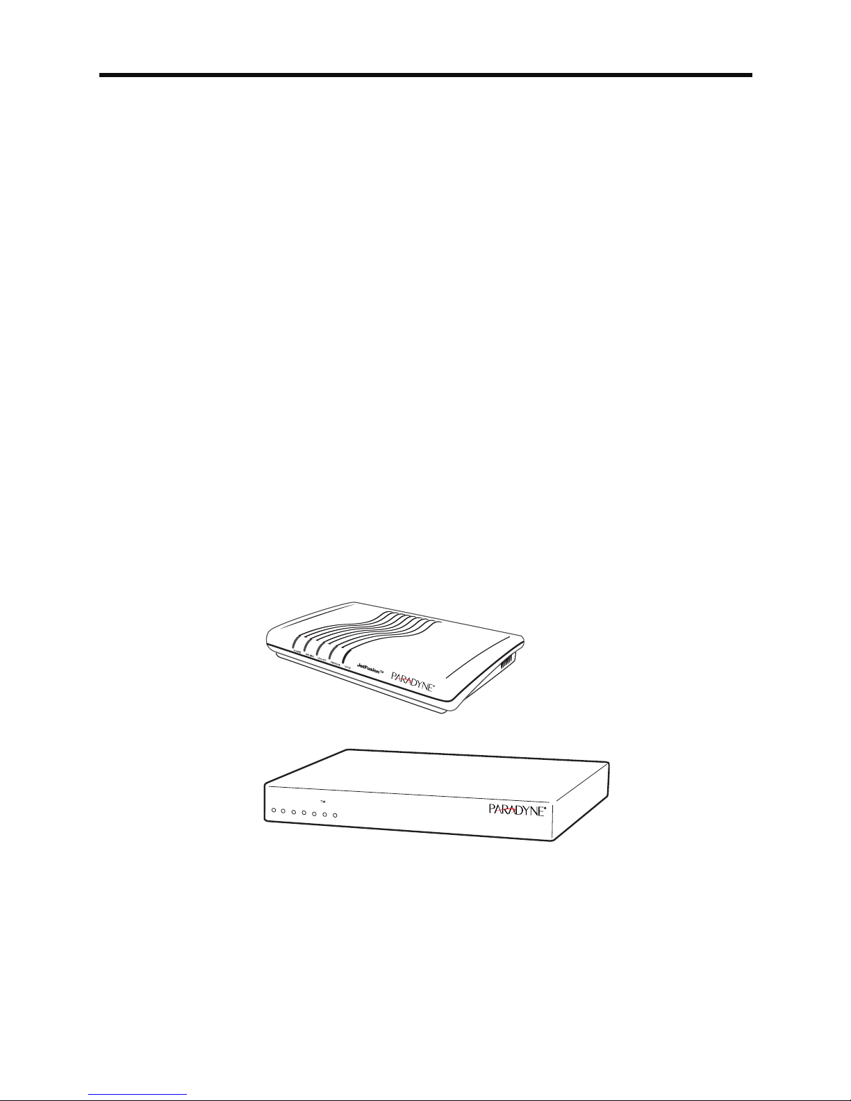
This chapter introduces the JetFusion Integrated Access Devices (IAD)
and describes their hardware and software. You should be aware of the
characteristics of each IAD to properly install and configure them for
operation in a customer’s premises.
This chapter provides information about these topics:
JetFusion 2/4/8-port IAD features, indicators and connectors (page 2)
JetFusion 16/24-port IAD features, indicators and connectors (page 4)
JetFusion IADs are ideal for service providers offering small to medium
businesses (or business units) a high quality voice and data service over
broadband circuits. With up to 24 POTS ports and full LAN support with a
full range of integrated features, each IAD offers toll-quality voice and high
speed Internet access over a single copper pair in one unit.
Each IAD supports any POTS device via its voice subsystem, and any IPbased computer system (Ethernet printers, personal computers—
Windows, Macintosh, Unix, Linux, etc.— network file servers, and other
network devices) via its LAN subsystem.
2/4/8-Port IAD
03-17481
16/24-Port IAD
JetFusion
POWER
LAN
LAN
WAN
VOICE
LINK
DCE
DCE
ACT
LINK
LINK
ACT
03-17482
Figure 1–1. JetFusion Integrated Access Devices
2000-A2-GB20-10 - 1 - February 2004
Page 21

Data
Interfaces
The data connection through the IAD supports IEEE 802.10-compliant
bridging and routing.
When the IAD is configured for routing, it supports Routing Information
Protocol (RIP) version 1, version 2, or static IP routing. The IAD complies
with RFC-1812 when interfacing with Version 4 IP routers.
The WAN subsystem supports the following interfaces:
ATM data transport via xDSL and T1/E1 per RFC 1483 or RFC 2364
Frame Relay data transport via xDSL and T1/E1 per RFC 1490
Frame Relay data transport per RFC 1483 with Q.922 frames
JetFusion
2/4/8-Port
IAD Family
The JetFusion 2/4/8-port IAD family provides a highly interoperable,
cost-effective voice and high-speed data integration solution that is
compatible with industry-leading DSLAM and Voice Gateway
manufacturers. These IADs prioritize voice packets and dynamically
allocate bandwidth between voice and data services.
Features
Interoperable with DSLAMs based on Alcatel, Texas Instruments,
MetaLink, and Globespan chip sets. These include Lucent Stinger/
TNT, Nokia Speedlink System, Promatory IMAS, AccessLan
PacketLoop, Accelerated Networks AN-3200, CopperMountain
CopperEdge, and Paradyne GranDSLAM DSLAMs, for example.
Seamless voice and high-speed data integration over xDSL or T1/E1
Supports data rates from 144 Kbps to 2.3 Mbps and customer premise
interfaces including POTS, 10/100BaseT Ethernet, BRI
Compatible with WAN protocols including ATM and Frame Relay
BRI IAD supports ISDN BRI telephone interface
RJ11 POTS interface with Loop Start or Ground Start
Dynamic and static IP routing and bridging capabilities
Firewall support via IP filtering
DHCP and NAT to support IP address management
Management capabilities including Telnet, SNMP and TFTP
IADs in the 2/4/8-port family are characterized by different WAN interfaces,
and different voice capacity:
JF2004 and JF2008 IADs—provide WAN access over ADSL, and
telephone support for 2, 4, or 8 voice ports.
JF2004i/JF2104i IADs—provide voice services and high-speed
Internet or corporate connectivity over ADSL (JF2004i) or G.SHDSL
(JF2104i), plus 4 ISDN Basic Rate Interface (BRI) ports for up to 8
voice extensions.
JF2104 and JF2108 IADs—provide voice services and high-speed
Internet or corporate connectivity over G.SHDSL, and provide 4 or 8
voice ports.
JF2208 IAD—provides WAN access via T1 lines, and provides 8 voice
ports.
2000-A2-GB20-10 - 2 - February 2004
Page 22
JF2304 and JF2308 IADs—provide voice services and high-speed
Internet or corporate connectivity over SDSL, and provide 4 or 8 voice
ports.
Physical and electrical specifications for each IAD are listed in Appendix
C, JetFusion IAD Specifications on page 254.
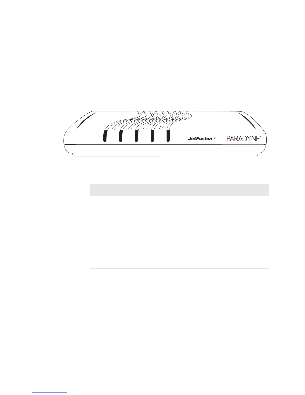
Front Panel Power and Status Indicators
The front panel of the IAD contains several LEDs. These LEDS provide
general information about the operational status of the IAD.
Figure 1–2. 2/4/8-Port Family Front Panel Indicators
LAN LINK LAN ACT WAN LINK VOICEPOWER
03-17479
Table 1–1. 2/4/8-Port Family Front Panel Indicators
LED Description
POWER Illuminates when the IAD is powered on.
LAN LINK Illuminates when there is an operational LAN connection
on the Ethernet port.
LAN ACT Flashes when there is activity on the Ethernet port.
WAN LINK Flashes as the IAD is establishing a link, and illuminates
solid when there is a proper connection on the WAN port
and synchronization has been achieved.
VOICE Illuminates when there is activity on the voice ports.
When connected to a Jetstream Voice Gateway, it
remains lit, and blinks when there is activity.
2000-A2-GB20-10 - 3 - February 2004
Page 23

Rear Panel Connectors
On the rear panel (Figure 1–3), the IAD contains several connectors. The
type and position of the WAN and telephone connectors vary by IAD.
Figure 1–3. Typical 2/4/8-Port Family Back Panel Connectors
Console (DB-9)
Serial Connector
POTS Telephone Lines
RJ-11 Jacks
PWR
Power
Receptacle
CONSOLE
Ethernet (RJ-45)
10/100 LAN
LINE
1 LINE 2 LINE 3 LINE 4
LINE 5 LINE 6 LINE 7 LINE 8
WAN Module
RJ-45 or RJ-48C Jack
WAN
DC Power Adapter
Connects the IAD to any AC outlet of 90-250 volts via an external, 18 volt
power supply.
RS-232 Console Port
Connects the IAD to a PC using a straight through 9-pin serial (DB9 RS-
232) cable, for the purpose of using a terminal emulator for IAD
configuration and management.
10/100Base-T Ethernet Port
Connects the IAD to the local area network using a CAT-5 straight through
Ethernet cable, or directly to a PC for accessing via Telnet (using a crossover cable, customer-supplied).
WAN Interfaces
Depending on the IAD, WAN interfaces include the following:
T1/E1—uses an RJ48 connector for the connection.
G.SHDSL—uses an RJ11 connector for the connection.
SDSL—uses an RJ45 connector for the connection.
ADSL—uses an RJ45 connector for the connection.
Telephone Interfaces
2/4/8-port IADs have varying telephone capacity. These IADs support:
2, 4, or 8 analog telephones via RJ11 POTS ports
—or—
8 telephone extensions via 4 BRI ISDN S0 ports.
JetFusion
16/24-Port
The JetFusion 16/24-port IAD family provides a highly interoperable,
cost-effective broadband solution for voice and high-speed data
integration that is compatible with industry-leading DSLAM and Voice
IAD Family
2000-A2-GB20-10 - 4 - February 2004
Page 24

Gateway manufacturers. These IADs prioritize voice packets and
dynamically allocate bandwidth between voice and data services.
Features
Interoperable with DSLAMs based on Alcatel, Texas Instruments,
MetaLink, and Globespan chip sets. These include Lucent Stinger/
TNT, Nokia Speedlink System, Promatory IMAS, AccessLan
PacketLoop, Accelerated Networks AN-3200, Coppermountain
CopperEdge, and Paradyne GranDSLAM DSLAMs, for example.
Seamless voice and high-speed data integration over xDSL or T1/ITE1
Supports data rates from 144 Kbps to 2.3 Mbps and customer premise
interfaces including POTS, 10/100BaseT Ethernet
Compatible with WAN protocols including ATM and Frame Relay
RJ21X POTS interface with Loop Start or Ground Start
Universal Serial Interface supports V.35 and EIA-530
Dynamic and static IP routing and bridging capabilities
Firewall support via IP filtering
DHCP and NAT to support IP address management
Management capabilities including Telnet, SNMP and TFTP
16/24-port IADs are characterized by different WAN interfaces and
different voice capacity:
JF2216 IAD—provides WAN access over T1/E1, and telephone
support for 16 voice ports via RJ21X connector.
JF2216c IAD—provides WAN access over channelized T1, and
telephone support for 16 voice ports via RJ21X connector.
JF2316 IAD—provides WAN access over SDSL, and telephone
support for 16 voice ports via RJ21X connector.
Physical and electrical specifications for each IAD are listed in Appendix
C, JetFusion IAD Specifications on page 254.
Front Panel Power and Status Indicators
The front panel of the IAD contains several LEDs. These LEDs provide
general information about the operational status of the IAD.
Figure 1–4. 16/24-Port IAD Front Panel
Front Panel
POWER LAN
LAN
WAN
VOICE
LINK
ACT
LINK
DCE
LINK
Status Indicators
DCE
ACT
03-17483
2000-A2-GB20-10 - 5 - February 2004
Page 25
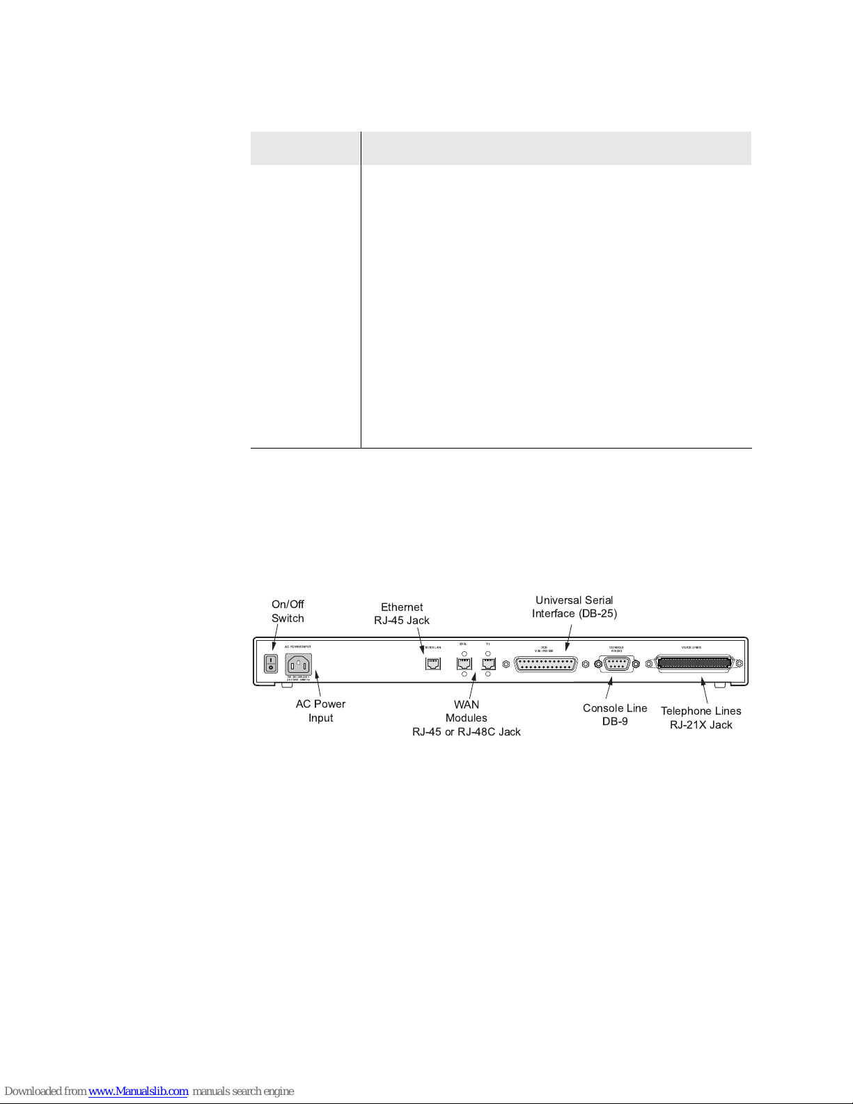
Table 1–2. Front Panel LEDs
LED Description
POWER Illuminates when the IAD is powered on.
LAN LINK Illuminates when there is an operational LAN connection
on the Ethernet port.
LAN ACT Flashes when there is activity on the Ethernet port.
WAN LINK Flashes as the IAD is establishing a link, and illuminates
solid when there is a proper connection on the DSL WAN
port and synchronization has been achieved.
VOICE Illuminates when there is activity on the voice ports.
When connected to a Jetstream Voice Gateway, it
remains lit, and blinks when there is activity.
DCE LINK Illuminates when there is a link between the IAD and
data communications equipment (DCE).
DCE ACT Illuminates or blinks when there is activity on the DCE
link.
Rear Panel Connectors
On the rear panel, the IAD contains several connectors. The WAN
connectors vary by IAD—both are present, but one has a permanently
attached metal shield to prevent use.
Figure 1–5. 16/24-Port IAD Back Panel
+ +,,
-.*
/+) 0/1
!
" " # $%
/.
0*
)**
-&-
12 -
0*, 3&'4
!"5 -5
&'(
+-+)
-5
!+0)0)-&)
AC Power
Connects the IAD to an AC outlet of 108-130 volts via an AC power cord.
10/100Base-T Ethernet Port
Connects the IAD to the local area network using a CAT-5 straight through
Ethernet cable, or directly to a PC for accessing via Telnet (using a crossover cable, customer-supplied).
WAN Interfaces
Depending on the IAD, WAN interfaces include the following:
T1/E1—uses an RJ48 connector for the connection.
SDSL—uses an RJ45 connector for the connection.
2000-A2-GB20-10 - 6 - February 2004
Page 26

Universal Serial Interface (USI) Port
The USI port is configurable for RS-530 or V.35. When configured as an
RS-530 port, you may use a straight through DB25 serial cable for
connection to your leased line DSU/CSU equipment. When configured for
use as V.35, Black Box Corporation provides a cable (FA058) for
conversion purposes. To convert from RS-530 to RS-449, Black Box
provides a cable EDN57J. By notifying you of their availability, Paradyne
neither endorses or recommends these products.
For USI port pinouts when configured as RS-530, V.35 or RS-449, see
Table D–9 on page 267.
RS-232 Console Port
Connects the IAD to a PC, using a straight through 9-pin serial (DB9 RS-
232) cable for the purpose of using a terminal emulator for configuration
and management.
Telephone Interfaces
Each 16/24-Port IAD supports 16 or 24 analog telephones via an RJ11
jack.
2000-A2-GB20-10 - 7 - February 2004
Page 27

4XLFN6WDUW*XLGH
This chapter describes the steps to install, connect, and set the IP address
of the JetFusion IAD. It introduces the menu interface and describes how
to perform basic configuration for common LAN and WAN environments. It
also describes basic operations—resetting the IAD, and logging off.
In many cases, all the information you need to get an IAD up and running
in a customer’s premises is contained in this single chapter.
This chapter contains the following topics:
Unpacking the IAD (page 9)
Installing the IAD (page 9)
Connecting via Terminal Emulator (page 10)
Resetting the IAD (page 9)
Powering up the IAD (page 10)
Logging on to the IAD (page 11)
Setting the Ethernet port IP address (page 12)
Connecting via Telnet (page 15)
Basic IAD configuration (page 19)
Connecting the LAN, WAN, USI and Telephones (page 19)
Confirming proper setup (page 21)
In most installations, you’ll proceed through these topics in order. If your
situation varies, complete information on installation, connection,
configuration and troubleshooting is contained in the reference chapters
following this chapter.
NOTE
When the IAD prompts you for input, the current value is
displayed in parentheses. To conveniently accept the current
value, just press Enter.
2000-A2-GB20-10 - 8 - February 2004
Page 28

Unpacking
LAN LINK LAN ACT WAN LINK VOICEPOWER
LAN LINK LAN ACT WAN LINK VOICEPOWER
the IAD
Each IAD is packed and shipped in a durable container. If you haven’t
already done so, open the container and unpack the IAD. Carefully
remove the IAD from the package and packing material.
IAD Package Components
Each IAD is shipped with the components listed below. As you unpack
them, note their condition and identity, and compare the list to the packing
list in the package.
AC power adapter and cord (6 feet long), or AC power cord
Agency Compliance information sheet
Ethernet cable (straight through), 7 feet long
WAN cable (varies by interface), 7 feet long
If you note any visible damage, or components are missing, notify the
shipping company immediately to make a damage claim. Contact the
company from which the IAD was purchased to obtain a Return Material
Authorization (RMA) for return of damaged equipment, or to order missing
components.
Installing
the IAD
NOTE
We suggest you keep the shipping container and packing
material for future shipping or storage of the unit.
After you unpack the IAD, find a suitable location to install the IAD in the
customer’s premises. Ideal locations include computer equipment room, or
a telephone or wiring closet. You can locate the IAD in an equipment rack,
on a table or shelf, or it may be wall-mounted. Install the IAD in a location
that is generally protected and the IAD will be undisturbed.
AC Power and Uninterruptible Power Supply
The IAD requires access to AC power (NEMA 15-3R). Make sure the IAD
is located within six feet of an AC power outlet. Locate the nearest power
outlet and plug in the supplied AC power adapter or AC power cord. If
there is an uninterruptible power supply on premises, plug the AC power
adapter or cord into that power source.
Ensure that the power cord conveniently and safely reaches the rear panel
of the IAD where the power plug or adapter jack is located.
2/4/8-Port
16/24-Port
Do not attach the AC power adapter, or power up the unit at
this time.
Plug in the power cord, but do not power up the unit
Clearance Requirements
If you install the IAD horizontally, make sure you maintain at least 2 inches
of horizontal distance from other IADs or other electronic equipment, to
ensure adequate ventilation and heat dissipation. If you install the IAD
2000-A2-GB20-10 - 9 - February 2004
Page 29

vertically, ensure at least 3 inches of distance between other IADs or other
equipment.
Connect
via
Terminal
Emulator
NOTE
2/4/8-port IADs may be stacked on top of one another, when
mounted horizontally. 16/24-port IADs may be rack mounted.
Wiring Requirements
Make sure that the telephone wiring, LAN and WAN cables reach the IAD
and can be dressed in a manner that is safe for the wiring, does not pull or
create lateral stress on the connectors or ports on the rear of the IAD, and
does not present a trip hazard to personnel working in the vicinity of the
equipment. Do not connect any cables or wiring at this time.
The IAD is configured and managed from either the console or Ethernet
port. Most network engineers use Telnet to access the IAD via Ethernet.
After you use a terminal emulator program via the console port to set the
IP address, you may continue to use a terminal emulator via the console
port if you choose.
NOTE
Before you can connect to the IAD via Telnet, make sure the IP address is
set correctly for this network. To do so, follow the steps, each described in
detail below:
1. Connect the IAD to a PC
2. Log in to the IAD
3. Set the IP address
After a period of inactivity (three minutes by default), the IAD
automatically terminates console-based and Telnet sessions
to maintain security. To change this value, see Configuring
the Console Timeout Period on page 36.
NOTE
Be sure that the IAD and PC are both powered OFF before
connecting the console cable. If both devices are not turned
off when you connect the cables, you may place the IAD in an
unstable state, and you may need to reset one or both
devices before you can perform configuration tasks.
Connect the IAD to a PC
To connect the IAD to a PC via the console port:
1. Turn off both devices and insert the male connector of a DB9 serial
cable into the console port on the IAD.
2. Insert the female connector of the cable into a serial (COM) port on
your PC.
NOTE
See RS-232 DB-9 Console Port Pin Assignments on page
265 for console port specifications.
Power Up the IAD
1. With the console cable connected, on 2/4/8-port IADs plug the AC
power adapter into the IAD. On 16/24-port IADs, turn on the power
2000-A2-GB20-10 - 10 - February 2004
Page 30

switch, located on the back panel. This starts the IAD and it executes
the boot process to begin normal operation.
2. Verify that the Power indicator on the front panel illuminates.
NOTE
As the IAD boots, it sends status messages to the console
port. If you are connected, you will see the boot sequence
progress.
Log in via a Terminal Emulation Program
With a serial cable connected, follow these steps to log in to the IAD:
1. Open a terminal emulation program (Hyperterminal, for example).
2. Select the COM port to which the IAD is connected.
3. Type or select the following settings and save your changes.
Table 2–1. Terminal Emulator Settings
Setting Value Setting Value
Bits per second 19,200
Data bits 8
Parity None
4. Press Enter. The IAD displays the log in message:
Enter Login ID >
NOTE
If the IAD does not respond, make sure the IAD is powered
up, check the cable and connections, and review the settings.
Stop bits 1
Flow control None
Emulation ANSI or VT100
5. Type the default supervisor level user ID (Supervisor) (or your user
ID if changed) and press Enter. Note that both the user ID and
password are case-sensitive.
Table 2–2 below lists the default user IDs and passwords.
Table 2–2. Default IAD User IDs and Passwords
Security Level User ID Password
User <enter> <Enter>
Network
NetMan <Enter>
Administrator
Supervisor Supervisor supervisor
For information on security levels, and user ID and password management
see IAD Security on page 23.
6. The IAD displays the password message:
Enter Password >
7. Type the default password (supervisor, or your password if
different) and press Enter.
8. If log in is not successful, the IAD displays the following message:
Invalid UserID or Password - Try again
Press any key to continue...
2000-A2-GB20-10 - 11 - February 2004
Page 31

9. Press any key, and repeat the log in sequence. If you cannot log in, call
your support provider for assistance.
When you first log in, the IAD displays the Main menu. The menu may
vary, depending on the IAD.
Figure 2–1. Main Menu
*****************************************
Main Menu
*****************************************
1. Reports Menu
2. Configure IP Router
3. Configure Bridge
5. Configure WAN
6. Configure LAN
7. Configure SNMP
8. Configure Login
9. System Utilities
D. Configure DHCP Server
M. Configure Multicast
N. Configure NAT
T. Telephony Clock Recovery
Z. Diagnostics Menu
C. Command Line Interface
R. Reset System
Options E, A and O
vary, depending on the
voice gateway selected
in the Voice Path
Configure command.
P. Voice Path Configure
E | A | O. CopperCom Call Control
Setting the Ethernet Port IP Address
Before you configure the Ethernet IP address, you should know the IP
address and subnet mask that is to be assigned to this port. It may be
displayed on the work order, or you may obtain or determine the
appropriate IP address by consulting with the network administrator.
The IAD is shipped with a null IP address and subnet mask. To configure a
port IP address:
1. On the Main menu, type 2 to select Configure IP Router.
2. The IAD displays the Router Configuration menu.
2000-A2-GB20-10 - 12 - February 2004
Page 32

Figure 2–2. Router Configuration Menu
*****************************************
Router Configuration Menu
*****************************************
C. Configure Port IP Address
U. Unconfigure Port IP Address
M. Configure Port Max Transmission Unit
S. Add/Remove a Static Route
R. Enable/Disable RIP
V. Configure RIP Version by Port
P. Configure RIP Poisoned Reverse by Port
N. Configure DNS Client
H. Configure DHCP Client
L. Configure DHCP Relay
T. Configure Telnet Server Port
F. Configure IP Filtering
Q. Configure IP Header Compression
B. Configure LAN IP Broadcast Destination
D. Display Route Table
Type C to select Configure Port IP Address.
3. The IAD displays the following menu (sample—all options shown). The
interfaces that display depend on the specific IAD:
Figure 2–3. Router Configuration Menu
Available Interfaces:
1. G2237 xDSL
1. G7070 ADSL ATU-R
1. T1/E1
1. SDSL
2. 10/100BaseT Ethernet
0. (Abort)
Type 2 to set the IP address for the Ethernet port.
4. If the IP address is configured for the port, the IAD displays information
about the interface and a prompt:
IP interfaces on port 2:
ID IPAddr IPMask Priority
0 92.1.1.90 255.255.255.0 NORMAL
Enter connection to configure:
Type the ID number of the connection that you want to configure (in
this case, 0) and press Enter.
5. Type the new IP address, and press Enter (or press Enter to retain the
current IP address).
6. The IAD displays the following information:
Current subnet mask = 0.0.0.0
Enter new subnet mask for this interface:
2000-A2-GB20-10 - 13 - February 2004
Page 33

Type the new subnet mask (usually 255.255.255.0) and press Enter.
7. The IAD displays the following instructions:
Select priority Normal/High [N/H] (N):
Give the interface normal priority—type N or press Enter.
8. Type Y or Enter to save the new IP address and subnet mask.
9. To exit, press Escape, then type Y to terminate the session.
10. Quit the terminal emulator program.
11. Reset the IAD (following) for the new IP address to be in effect.
Resetting
the IAD
NOTE
When you configure the IAD, you must restart the IAD each
time you change the settings for those changes to take effect.
You may make several configuration changes before
resetting if you choose, for efficiency.
If you plan to use Telnet for configuration tasks, this is a good time to
disconnect the serial cable from the PC and IAD.
Many configuration tasks require that you reset (or restart) the IAD before
the new settings or configuration will take effect. When you use the menu
interface (or the Command Line Interface on page 221) to make changes,
or change the physical characteristics of the IAD (such as changing the
Ethernet port MAC address), you must reset the IAD.
The IAD stores all configuration settings in memory. When it restarts, it
loads the last configuration saved before it was powered down or
restarted. When restarting is required, it will be included as a step in the
configuration process.
You can reset the IAD in two ways.
To reset the IAD from the menu:
1. On the Main menu, type R to select Reset System.
The IAD displays the following instructions:
Press R to Reset now->
2. Type R again. This resets and starts the IAD with your new settings.
3. To log in again, enter your user ID and password.
To reset the IAD manually:
On a 2/4/8-port IAD, unplug the power adapter from the IAD and then plug
it back into the IAD. On a 16/24-port IAD, turn the IAD off, then back on.
Be sure to complete your task and return to the Main menu before
restarting the IAD in this manner.
CAUTION
2000-A2-GB20-10 - 14 - February 2004
Resetting the IAD terminates all telephone calls and
computer sessions in progress. You should ensure that there
no services are being rendered before resetting the IAD.
Page 34

Connecting
via Telnet
To manage the IAD via the LAN (or Intranet), you must set an IP address
for the Ethernet port before you can use Telnet to access the IAD.
NOTES
Although you can also access the IAD using Telnet via the
WAN (provided a management DLCI or PVC is configured
along with a WAN IP address), this section describes
connecting via the LAN. For information about setting the IP
address of the WAN port, see Chapter 6, WAN Configuration
on page 48.
If you configure a RADIUS server, you must use a RADIUSauthenticated User ID/password for Telnet access. If the
RADIUS server or the connection to the RADIUS server goes
down, Telnet access will not work. For information about
configuring a RADIUS server, see RADIUS Server Settings
on page 26.
Running Telnet
Before you use Telnet to log in to the IAD, make sure that the IAD and your
PC are connected to the same network via straight-through Ethernet
cables (or directly connected via a cross-over cable), and you know the IP
address of the IAD. Both devices must be on the same subnet.
Follow these steps to log in:
1. Run Telnet on your PC.
2. Type the IP address of the Ethernet port (page 12), click Connect and
then press Enter to gain the attention of the IAD.
3. The IAD responds by displaying the log in message:
Enter Login ID >
4. Type your user ID and press Enter.
NOTE
After a period of inactivity (three minutes by default), the IAD
automatically terminates console-based and Telnet sessions
to maintain security. To change this value, see Configuring
the Console Timeout Period on page 36.
Default user IDs and passwords are listed in Table 2–2 on page 11. For
information on security levels, and user ID and password management
see IAD Security on page 23.
5. The IAD displays the password message:
Enter Password >
2000-A2-GB20-10 - 15 - February 2004
Page 35

4.Type your password and press Enter to display the Main menu.
*****************************************
Main Menu
*****************************************
1. Reports Menu
2. Configure IP Router
3. Configure Bridge
5. Configure WAN
6. Configure LAN
7. Configure SNMP
8. Configure Login
9. System Utilities
D. Configure DHCP Server
N. Configure NAT
T. Telephony Clock Recovery
Z. Diagnostics Menu
C. Command Line Interface
R. Reset System
P. Voice Path Configure
Using the
Menu
Interface
NOTE
The JetFusion IAD provides an ANSI-terminal-based menu interface for
system configuration and monitoring. When you log in, the IAD displays
the Main menu.
The commands displayed in some menus (including the Main menu) differ,
depending on the level at which you log in. Figure 2–4 on page 17 displays
the Main menu when you log in at the Supervisor security level. Figure 2–
5 on page 17 displays the Main menu when you log in as Network
Administrator, and Figure 2–6 on page 17 displays the Main menu when
you log in as User.
The user ID and password transmit as clear text, which may
be captured by unauthorized individuals. If you are concerned
with network security, you may not want to use Telnet to
configure the IAD.
2000-A2-GB20-10 - 16 - February 2004
Page 36

Figure 2–4. Main Menu for Supervisor
*****************************************
Main Menu
*****************************************
1. Reports Menu
2. Configure IP Router
3. Configure Bridge
5. Configure WAN
6. Configure LAN
7. Configure SNMP
8. Configure Login
9. System Utilities
D. Configure DHCP Server
M. Configure Multicast
N. Configure NAT
T. Telephony Clock Recovery
Z. Diagnostics Menu
C. Command Line Interface
R. Reset System
P. Voice Path Configure
Options E, A and O vary,
depending on the Voice
Gateway selected in the
Voice Path Configure
command. These options
only display when logged
on as Supervisor.
E. Toggle CMCP Debugging
O. Manage MGCP Embedded Client Selection
Figure 2–5. Main Menu for Network Administrator
*****************************************
* Main Menu *
*****************************************
1. Reports Menu
2. Configure IP Router
3. Configure Bridge
7. Configure SNMP
8. Configure Login
9. System Utilities
D. Configure DHCP Server
M. Configure Multicast
N. Configure NAT
Z. Diagnostics Menu
R. Reset System
Figure 2–6. Main Menu for User
*****************************************
Main Menu
*****************************************
1. Reports Menu
8. Configure Login
2000-A2-GB20-10 - 17 - February 2004
Page 37

Navigating the IAD Menu Interface
Menus in the IAD configuration system are arranged hierarchically. That is,
you select single-key options to navigate down to display specialized
menus and specific tasks, and press the Escape key successively to
return back to menus higher in the interface.
The specific menus, submenus and commands that display depend on the
interfaces for the specific IAD, the options configured and the security level
that you use to log in.
To select a menu item, just type the option displayed to the left of the item.
Although character options are displayed in upper case, the IAD accepts
both upper and lower case options. It is not necessary to press Enter after
typing the selection to execute it—the IAD immediately responds with a
request for input or another menu for more options.
For a hierarchical map of the Main menu, its menus and commands, see
Appendix A, Menu Map on page 250.
Entering Settings and Values
When the IAD requests input for a setting or configuration value, type it at
the prompt. Press the Enter key to terminate the input and proceed to the
next step.
The IAD responds with error messages if a value is incorrect, or it displays
the current menu so you can continue with related tasks.
Using Default or Current Values
The IAD displays a default or current value in parentheses immediately to
the right of each message, just to the left of the command prompt. To
accept this value, just press the Enter key.
For example, when the following message displays:
Enter a new subnet mask for this interface:
(255.255.255.0) -)
You may press Enter to cause the IAD to set 255.255.255.0 as the
subnet mask value. Using the Enter key to skip through default or current
values often speeds the process of proceeding through a family of input
steps, to quickly get to the input step where you want to change a value.
2000-A2-GB20-10 - 18 - February 2004
Page 38

Exiting the Menu Interface
To exit the menu interface, return to the Main menu using the Escape key,
and press Escape one more time. The IAD asks you to confirm—press Y
to exit (or press Return to accept the default value (N) to cancel the exit).
After exiting, you can quit the terminal emulator or Telnet application. If you
made changes to the configuration that require resetting the IAD, be sure
to do so before exiting.
Basic IAD
Configuration
Connecting
LAN, WAN,
USI and
Telephones
Each IAD has a default configuration when it is shipped from the factory. At
a minimum, you should view the configuration and check the following
settings for probable update for each customer installation:
1. Configure the LAN IP address, if not already completed (page 12)
2. Configure each of the WAN options and the DSLAM profile (WAN
Configuration on page 48)
3. Create and configure at least one DLCI (page 86) or PVC (page 75) for
data traffic and set the WAN IP address (WAN Configuration on page
48.)
4. Configure static or default route or enable bridging for all data traffic
5. Create and configure a DCLI (page 86) or PVC (page 75) for voice
where required and select appropriate voice gateway settings.
6. Reset the IAD (page 14) to enable all configuration changes.
In this section, you’ll connect the IAD to the computer and telephone
systems the IAD is intended to support.
Before proceeding, make sure that you have an appropriate serial cable
for your PC, identify the LAN switching equipment where you’ll connect the
IAD, identify the telephone cables, and verify that WAN service is installed,
and configured by the service provider.
When you’ve completed this section, reset the IAD so it can synchronize
these physical connections.
Ethernet LAN Connection
The Ethernet LAN port on the rear of the IAD is an RJ45 jack for 10/
100Base-T Ethernet cables. If the IAD is intended to act as an Internet
gateway for the LAN in the customer’s premises, connect the IAD to the
switch, hub or router using an Ethernet straight-through cable.
NOTE
WAN Connections
WAN connections vary, based on the WAN interface on your IAD. Identify
the WAN interface on your IAD, and proceed to the appropriate section.
2000-A2-GB20-10 - 19 - February 2004
To temporarily connect the IAD directly to a PC for Telnet
configuration (without going through a hub or router), be sure
to use an Ethernet cross-over cable (customer-supplied).
Page 39

Making G.SHDSL Connections
LAN LINK LAN ACT WAN LINK VOICEPOWER
G.SHDSL-equipped IADs use an RJ11 connector on the rear panel for
WAN connection. To make the connection, plug the WAN cable into the
RJ11 WAN connector. Table D–7 on page 266 lists the G.SHDSL
connector pinouts.
Making SDSL or ADSL Connections
SDSL- and ADSL-equipped IADs use an RJ45 connector on the rear panel
for WAN connection. To make the connection, plug the xDSL cable into the
RJ45 WAN connector. Table D–6 on page 266 lists the RJ45 WAN pinouts.
Making T1/E1 Connections
T1/E1-equipped IADs use an RJ48 connector on the IAD rear panel for
WAN connection. To make the connection, plug the cable from the ATM
network into the RJ48 WAN connector. Table D–8 on page 267 lists the
pinouts for the T1/E1 connector.
USI Connection (16/24-Port)
7300
2x16
2x24
16/24-port IADs have a Universal Serial Interface (USI) port,
configurable for V.35 or EIA-530 (page 36).
If your IAD is equipped with a USI port, you may connect it now. Located
on the rear panel, the port uses a shielded, DB25 connector. The
connector is DCE—data is transmitted on the receive pin and received on
the transmit pin.
The V.35 or EIA-530 interfaces use different voltage levels. You must
supply the appropriate cable for each interface. Table D–9 on page 267
lists the USI port pinouts and signal specifications.
Telephone Connections
2/4/8-port IADs provide RJ11 ports for POTS devices, or ISDN connectors
for telephone service. 16/24-port IADs provide an RJ21X Amphenol-style
connector for connecting up to 16 telephone devices.
These devices may be POTS telephones, modems, FAX machines, or
other POTS-compatible devices.
Making RJ11 Connections (2/4/8-port)
The RJ11 POTS port pinouts are telco standard (RJ11 POTS Port Pin
Assignments on page 265). Connect each telephone device to the RJ11
jacks using 26AWG telephone cord or better (user provided).
Making ISDN Connections (JF2004i, JF2104i)
The RJ45 BRI IDSN S0 ports are telco standard (RJ45 BRI ISDN S0 Port
Pin Assignments on page 265). Connect each ISDN cable from the ISDN
terminal equipment to the S0 ports on the back of the IAD using 4-wire
cable. The ports provide PS1 and PS2 powering for ISDN telephones, at
10 power consumption units per port.
2000-A2-GB20-10 - 20 - February 2004
Page 40

Making RJ21X Connections (16/24-Port)
The pin assignments for the RJ21X connector are telco standard. Connect
telephone devices from an RJ11 jack field, or a punch down block. Each
line provides a two-wire loop or groundstart connection. To perform the
connection, use a customer-provided cable terminated at one end with an
RJ21X connector. After connecting each color-coded wire pair to the
corresponding telephone connection on the jack field or punchdown block,
connect the RJ21X connector to the connector on the IAD rear panel.
Confirming
Proper
Setup
When you have completed the tasks in this chapter, reset the IAD and test
your configuration.
Reset the IAD
Reset the IAD (page 14) to synchronize the physical connections.
Verify Normal Power Up and Operation
Finally, to test your configuration for proper data and voice operation,
perform the operational test (Operational Test on page 247).
2000-A2-GB20-10 - 21 - February 2004
Page 41

$GPLQLVWUDWLRQ
This chapter describes how to control security to your IAD, validate users
using a RADIUS server, configure SNMP via IP or EOC, upgrade IAD
software, and perform other general and utility-oriented tasks.
This chapter includes these topics:
IAD security—setting user IDs and passwords (page 23)
Using a RADIUS server for authentication (page 26)
Configuring SNMP (page 28)
Upgrading IAD system software (page 32)
Upgrading ACOS (page 44)
Configuring the IAD for LAN connection (page 34)
Using system utilities (page 23)
Setting derived timing options (page 46)
Resetting the IAD (page 14)
NOTE
When the IAD prompts you for input, the current value is
displayed in parentheses. To conveniently accept the current
value, just press Enter.
2000-A2-GB20-10 - 22 - February 2004
Page 42

IAD
Security
To maintain IAD security, the IAD provides multi-level login access using a
single user ID and password, which you can set at the following levels:
User
Network Administrator
Supervisor
The user ID at the User security level may be modified, but the user ID at
the Network Administrator and Supervisor level may not be modified.
The password for each security level may be changed. Although you may
use the same password for all security levels, Paradyne recommends that
you use a different one for each level. Table 3–2 lists the privileges
available at each security level.
Table 3–1. Security Level Privileges
Security level Privileges
Supervisor This user level is the highest level. Users who
log in as Supervisor have full access to all IAD
features (menu and command line interface,
including changing User security level user ID
and any level passwords, plus complete IAD
configuration capability.
Network Administrator This user may perform tasks that alter the
network settings of the IAD, plus has access to
all of the data networking configuration menus,
and can update routing and bridging
information and status.
This user can change this level password, and
the User level user ID and password, and has
access to all display-only menus.
This user may not modify WAN or LAN
settings, alter derived timing, use command
line interface, or modify voicepath settings.
User This user has access to display-only menus,
and may view the current configuration,
interface and media statistics, routing and
bridging information and status. This user may
change this level user ID and password. This
user may not make or save any changes to the
configuration of the IAD.
To maintain IAD security, a user with Supervisor privileges should modify
the User security level user ID and passwords for both User level and
Network Administrator level prior to placing the IAD into production.
2000-A2-GB20-10 - 23 - February 2004
Page 43

Table 3–2 lists the default values for the user IDs and passwords:
Table 3–2. Default User IDs and Passwords
Security Level User ID Password
User <Enter> <Enter>
Network
NetMan <Enter>
Administrator
Supervisor Supervisor supervisor
The user ID and password may contain up to 17 alphanumeric characters.
These values are case sensitive; spaces and punctuation characters are
not allowed.
NOTE
The IAD can only store one user ID and password at each
security level.
Changing a Password
To change a password at any security level, you must sign on at or above
the security level you’re changing and follow these steps:
1. On the Main menu, type 8 (Configure Login) to display the Password
Configuration menu.
Figure 3–1. Password Configuration Menu
*******************************************
Password Configuration Menu
*******************************************
1. Change User ID
2. Change User Password
3. Change NetMan Password
4. Change Supervisor Password
5. Change Primary RADIUS Server Address
6. Change Primary RADIUS Encryption Secret
7. Change Secondary RADIUS Server Address
8. Change Secondary RADIUS Encryption Secret
9. Display RADIUS Configuration
2. Type 2, 3, or 4 to change the password for the selected level.
3. Enter the password for the current level.
4. Enter the new password after the prompt, or press Enter to enter a null
password.
5. Enter the new password (or Enter) again, to confirm the change.
The IAD immediately updates the password. The next time you log in at
that level, the new password will be in effect.
2000-A2-GB20-10 - 24 - February 2004
NOTE
You cannot use the Escape key to exit the password update
command. To exit, deliberately enter an incorrect password at
the confirmation step, or reset the IAD.
Page 44

Changing the User Level User ID
To change the user ID for the User security level (the only security level
that allows the user ID to be changed), follow these steps:
1. On the Main menu, type 8 (Configure Login) to display the Password
Configuration menu.
2. Type 1 to change the user ID for the User security level.
Enter new User ID (up to 17 characters) >
3. Type the new User ID and press Enter. The IAD informs you that the
user ID has been updated.
4. Reset the IAD (page 14).
Including User ID and Passwords in Config Files
If you create master configuration files for distribution to multiple IADs, you
may include the userid and passwords directly in the configuration file to
reduce configuration tasks.
NOTE
When the user ID and passwords are stored in a
configuration file, the IAD saves the configuration file
immediately upon rebooting, without requiring the log on
process. The userid and passwords are stripped from the
configuration file before saving to prevent a security risk.
Using a text editor, update the config file by adding the following attributes
in the [user] category:
userid={string}
password={string}
netman-password={string}
support-password={string}
The password parameter is for user level access; netman-password is for
network administrator level access; and support-password is for
supervisor level access.
2000-A2-GB20-10 - 25 - February 2004
Page 45

RADIUS
Server
Settings
You can use a RADIUS server to determine the validity of unknown user
ID/password pairs in your IAD. To use a RADIUS server, set the following
options:
Change the primary or secondary RADIUS Server Address
Change the primary or secondary RADIUS Encryption Secret
Display RADIUS Configuration
NOTE
Paradyne does not provide a RADIUS server. You must
provide a RADIUS server to use this feature. For more
information on RADIUS servers, see RFC 2865.
If you configure a RADIUS server, the IAD must be able to successfully
connect to the RADIUS Server. This requires WAN configuration, IP
configuration, static or default routes and other configurations for your
network. Additionally, you must use a RADIUS-authenticated user ID/
password for Telnet access. If the RADIUS server becomes inoperative,
Telnet access will not work.
Changing the RADIUS Server Address
To change the primary or secondary RADIUS server address:
1. On the Main menu, type 8 (Configure Login) to display the Password
Configuration menu (page 24).
2. Type 5 to select Change Primary RADIUS Server Address or Type 7
to select Change Secondary RADIUS Server Address.
The IAD displays the following message:
Primary/Secondary RADIUS Server is currently:
Enter new Primary/Secondary RADIUS Server as either
an IP address or name >
3. Type the IP address in one of the following formats and press Enter:
IP address
Fully-qualified host and domain names
(for example: radius.xyz.com—maximum 42 bytes)
NOTE
4. Reset the IAD (page 14).
Changing the RADIUS Encryption Secret
To change the primary or secondary RADIUS encryption key:
1. On the Main menu, type 8 (Configure Login) to display the Password
Configuration menu (page 24).
2. Type 6 to select Change Primary RADIUS Encryption Secret or type 8
to change Secondary RADIUS Encryption Secret.
The IAD displays the following message:
Primary/Secondary RADIUS Encryption Secret is
currently:
Enter new Primary/Secondary RADIUS Encryption Secret
3. Type the new encryption key and press Enter.
2000-A2-GB20-10 - 26 - February 2004
If you enter host and domain names, you must configure the
IAD as a DNS client (page 106).
Page 46

4. Reset the IAD (page 14).
Displaying the RADIUS Configuration
To display the current RADIUS server configuration:
1. On the Main menu, select Configure Login to display the Password
Configuration menu (page 24).
2. Type 9 to select Display RADIUS Configuration.
The IAD displays the following information:
Primary RADIUS Server:
Primary RADIUS Secret:
Secondary RADIUS Server:
Secondary RADIUS Secret:
2000-A2-GB20-10 - 27 - February 2004
Page 47

Setting Up
SNMP
You can enable SNMP over IP and/or EOC (when the voice gateway is
AAL2/LES CAS or ELCP). By default, the IAD is configured with SNMP
disabled. When SNMP is enabled and the settings are configured, you can
use SNMP to remotely manage the IAD by getting and setting IAD values,
and monitoring IAD events.
The IAD supports the following SNMP settings:
System Contact
System Name
System Location
SNMP Community
SNMP Trap Host IP Address
af-vmoa-0172 (AAL2/LES)
The following SNMP traps are supported:
System reset
Attempts to access SNMP with an invalid community name
Starting and stopping TFTP within SNMP
The IAD supports MIBs for RFCs 1213, 1317, 1406, 1493, 1463 as well as
af-vmoa-0172 (AAL2/LES MIB).
Using the SNMP Configuration Menu
To display the SNMP Configuration menu, type 7 on the Main menu. The
following SNMP tasks are accessed from this menu:
Figure 3–2. SNMP Configuration Menu
*****************************************
SNMP Configuration Menu
*****************************************
E. Enable/Disable SNMP via IP
F. Enable/Disable SNMP via EOC
A. Enable SNMP via both IP and EOC
B. Disable SNMP via both IP and EOC
P. Configure System Contact
N. Configure System Name
L. Configure System Location
C. Configure SNMP Community
T. Configure SNMP Trap Host IP Address
U. Enable/Disable SNMP Traps via EOC
D. Configure Restart Trap Max Delay
When you are done updating SNMP settings, you must reset the IAD for
the new settings to take effect.
2000-A2-GB20-10 - 28 - February 2004
NOTE
The strings you enter in SNMP are not case sensitive.
Page 48

Enabling and Disabling SNMP via IP
Type E to enable or disable SNMP via IP:
1. The IAD displays the current status of SNMP and a prompt:
SNMP via IP is currently DISABLED
To enable SNMP, type E. To disable SNMP, type D.
2. The IAD saves the configuration (if changed). Continue with other
SNMP settings, or press Escape to return to the Main menu.
3. Reset the IAD (page 14) for changes to take effect.
Enabling and Disabling SNMP via EOC
Type F to enable or disable SNMP via EOC:
1. The IAD displays the current status of SNMP and a prompt:
SNMP via EOC is currently DISABLED
To enable SNMP, type E. To disable SNMP, type D.
2. The IAD saves the configuration (if changed). Continue with other
SNMP settings, or press Escape to return to the Main menu.
3. Reset the IAD (page 14) for changes to take effect.
Enabling SNMP via IP and EOC
Type A to enable SNMP via IP and EOC.
The IAD saves the configuration. Continue with other SNMP settings, or
press Escape to return to the Main menu.
Reset the IAD (page 14) for changes to take effect.
Disabling SNMP via IP and EOC
Type B to disable SNMP via IP and EOC.
The IAD saves the configuration. Continue with other SNMP settings, or
press Escape to return to the Main menu.
Reset the IAD (page 14) for changes to take effect.
Configuring the System Contact
Type P to configure system contact (up to 39 alphanumeric characters):
1. The IAD displays the current system contact and prompt:
System Contact is currently: Paradyne
Enter new System Contact >
Type the name of the new contact person or department and press
Enter.
2. The IAD save the configuration. Continue with other SNMP settings, or
press Escape to return to the Main menu.
3. Reset the IAD (page 14).
2000-A2-GB20-10 - 29 - February 2004
Page 49

Configuring the System Name
Type N to configure the system name (up to 39 alphanumeric characters):
1. The IAD displays the current system name and prompt:
System Description is currently:
Enter new System Description >
Type the new system name and press Enter.
2. The IAD saves the configuration. Continue with other SNMP settings,
or press Escape to return to the Main menu.
3. Reset the IAD (page 14).
Configuring the System Location
Type L to configure the system location (up to 39 alphanumeric
characters):
1. The IAD displays the current system location and prompt:
System Location is currently:
Enter new System Location >
Type the name of the new server location and press Enter.
2. The IAD saves the configuration. Continue with other SNMP settings,
or press Escape to return to the Main menu.
3. Reset the IAD (page 14) for changes to take effect.
Configuring the System Community
The value that you set must match the write community name of the
SNMP host to enable the SNMP Set operation. If you enable SNMP and
the read-write Community Name is null, SNMP enters read-only mode with
a community name of “public”.
Type C to select Configure System Location.
1. The IAD displays the current community name and prompts you to
enter a new name:
SNMP Community is currently:
Enter new SNMP Community >
Type the name of the SNMP community to which your system belongs
and press Enter.
2. The IAD saves the configuration. Continue with other SNMP settings,
or press Escape to return to the Main menu.
3. Reset the IAD (page 14) for changes to take effect.
Configuring the SNMP Trap Host IP Address
Type T to select Select Configure SNMP Trap Host IP Address of the
system setup for trap operations:
1. The IAD displays the current IP address and prompt:
Current SNMP Trap Host IP Address = 0.0.0.0
Enter new SNMP Trap Host IP address:
Type the IP address and press Enter.
2. The IAD saves the configuration. Continue with other SNMP settings,
or press Escape to return to the Main menu.
3. Reset the IAD (page 14) for changes to take effect.
2000-A2-GB20-10 - 30 - February 2004
Page 50

Enabling or Disabling SNMP Traps via EOC
Type U to enable or disable SNMP traps via EOC:
1. The IAD displays the current status and prompt:
SNMP traps sent via EOC are currently DISABLED
To enable traps via EOC, type E. To disable them, type D.
2. The IAD saves the configuration. Continue with other SNMP settings,
or press Escape to return to the Main menu.
3. Reset the IAD (page 14) for changes to take effect.
Configuring Restart Trap Maximum Delay
Type D to configure the restart trap maximum delay time:
1. The IAD displays the prompt:
Enter SNMP Restart Trap Maximum Delay Time in
Seconds (0..600): (0)
2. Type the new value in seconds and press Enter.
3. The IAD saves the configuration. Continue with other SNMP settings,
or press Escape to return to the Main menu.
4. Reset the IAD (page 14) for changes to take effect.
2000-A2-GB20-10 - 31 - February 2004
Page 51

Upgrading
the System
Periodically, Paradyne may provide new software that you will download to
the IAD to upgrade the system. You must use TFTP to perform the file
transfer when upgrading the entire system.
NOTE
To use TFTP, you must configure both the IAD and the computer that
contains the TFTP Server program, a program that you license separately.
Some gateways directly support file transfer as a means of
upgrading IADs. For information, refer to the Voice Gateway
manufacturer’s operating manual.
Using TFTP Servers via LAN or WAN
Before the IAD can access a LAN or Intranet-based TFTP server, you
must configure the IP address of the Ethernet port (page 12) on the same
subnet as your TFTP server, and the IAD must be connected to the LAN.
To access a WAN-based server, you must configure the T1/E1 or xDSL
Interface with a management DLCI or PVC and a WAN IP address. For
information about setting the IP address of the WAN port, see Chapter 6,
WAN Configuration on page 48.
Copying the Source Files
Typically, you will receive two ZIP files (a core ZIP file and an application
ZIP file) for each upgrade.
First, extract each file into a single directory on your PC. Then, set the
directory as the path that the TFTP Server will use to send files to the IAD
(often identified as upload/download or outbound directory).
Upgrading via TFTP
If your TFTP Server is not running, start it now and note the IP address of
the computer it is running on. To upgrade the IAD software:
1. On the Main menu, type 9 to display the Utilities menu:
Figure 3–3. Utilities Menu
*****************************************
Utilities Menu
*******************************************
P. Ping Utility
T. Trace Route
Z. Configure Console Baud Rate
V. Configure Console Timeout
R. Hard Reset or Reload ACOS from FLASH
D. Set System Default
W. Save System Settings as Defaults
E. Display Event Log
A. Clear "Last Reset Reason"
F. File System Menu
G. Debug Menu
X. File Transfer Menu
2000-A2-GB20-10 - 32 - February 2004
Page 52

2. Type X to display the File Transfer menu.
Figure 3–4. File Transfer Menu
*******************************************
File Transfer Menu
*******************************************
B. Load Boot ROM
O. Update ACOS [acos.bin]
X. Update Entire System
A. File Transfer Utilities
3. Type X to update the entire system (you must use TFTP).
Respond by typing Y to continue.
4. The IAD displays the following:
**** Download using TFTP ****
Enter ip address of TFTP server.
(98.121.1.167) ->
5. Type the IP address of the TFTP Server and press Enter.
As file transfer progresses, the IAD reports the status of each file being
copied. Two files—acos.bin and boot.bin—will only be copied if they match
the platform, to guard against loading incorrect system files onto an IAD.
NOTE
If the IAD cannot locate the first file to download (typically
release.dat), the update will fail. Make sure you have
assigned a valid IP address and subnet mask, and you’re on
the same subnet as the TFTP Server. Use the Ping command
to successfully ping the IAD and try again.
Upon completion, the IAD reports the success or failure of these files
specifically, and then reports the completion of file transfer and resets.
Verifying the Upgrade
To verify that the files downloaded successfully, observe the boot
sequence. The IAD displays the software version in the banner:
****************************************************
RTOS start sequence
****************************************************
Enter "i" to Inhibit Application Launching only
Enter "I" to additionally Inhibit Initialization (minimal startup)
****************************************************
<=> 2208 JetFusion IAD v3.5.0 <=>
****************************************************
You can also display the current configuration (page 182) to validate the
firmware version.
Oct 19 2003 15:33:52
2000-A2-GB20-10 - 33 - February 2004
Page 53

Setting up
Your LAN
Connection
The IAD LAN port may be set for full duplex Ethernet operation if your IAD
is set up as a router. Full duplex mode allows simultaneous transmission
and receipt of Ethernet packets.
On the Main menu, type 6 (Configure LAN) to display the LAN
Configuration menu.
Figure 3–5. LAN Configuration Menu
*******************************************
LAN Configuration Menu
*******************************************
1. 10 Mbps Full Duplex
2. 10 Mbps Half Duplex
3. 100 Mbps Full Duplex
4. 100 Mbps Half Duplex
5. Auto Negotiate the Speed, Full Duplex
6. Auto Negotiate the Speed, Half Duplex
7. Auto Negotiate Speed & Full/Half Duplex Mode
8. Display MII & FEC Registers
Selecting the Connection
If more than one connection is defined, the IAD prompts you to specify the
port number. Type the number of the port, select enable or disable and
press Enter.
Establishing LAN Speed and Duplex Mode
1. Type the option number of the speed and duplex mode.
2. The IAD saves the configuration. Press Escape to return to the Main
menu.
3. Reset the IAD (page 14) for changes to take effect.
NOTE
You can display the current LAN settings using the Display Current
Configuration command in the Reports menu (page 182).
Full duplex Ethernet operation is controlled by the switch. If
the switch is set to full duplex, you may enable it in the IAD. If
you enable full duplex Ethernet in the IAD when the switch is
operating in normal half duplex mode, your IAD will not
communicate on the LAN.
2000-A2-GB20-10 - 34 - February 2004
Page 54

Using
System
Utilities
The Utilities menu contains utility commands, and several menus to
upgrade ACOS software and support ACOS application development.
To display the Utilities menu, type 9 on the Main menu. 16/24-port IADs
display a menu with option U, the USI port command:
Figure 3–6. Utilities Menu
*******************************************
Utilities Menu
*******************************************
P. Ping Utility
T. Trace Route
U. Make a USI Module a UART port
Z. Configure Console Baud Rate
V. Configure Console Timeout
R. Hard Reset or Reload ACOS from FLASH
D. Set System Default
W. Save System Settings as Defaults
E. Display Event Log
A. Clear "Last Reset Reason"
F. File System Men
G. Debug Menu
X. File Transfer Menu
To perform a task, type the option and proceed to the appropriate section.
Pinging Network Devices
To check for a device on a network, follow these instructions:
1. Type P on the Utilities menu.
To set up Ping to run, supply the following information:
1. Type the IP address or complete host name. If you enter a host name,
you must enter the domain name with the host name. For example,
mycomputer.mydomain.com.
2. Type the ping packet size.
3. Type the number of times to ping (0 causes Ping to run until you press
Escape).
The IAD displays the following report:
Pinging: 91.1.1.217
Size: 32 bytes...
Ping Number 1 of 1 (Esc to quit)
Reply from: 91.1.1.217
Size: 32 bytes
Time: < 5 mS
**** Ping Summary ****
Packets Sent : 1
Packets Received : 1
Packets Lost : 0
Average Ping Time : < 5 ms
2000-A2-GB20-10 - 35 - February 2004
Page 55

Using Trace Route
LAN LINK LAN ACT WAN LINK VOICEPOWER
Use Trace Route to trace the network route to a specified host. To run
Trace Route, follow these steps:
1. Type X on the Utilities menu and press Enter.
2. Type the IP address or host name to trace and press Enter. If you enter
a host name, you must enter the domain name with the host name. For
example, mycomputer.mydomain.com.
The IAD displays each hop, as shown in the following sample report:
Trace Route Results to 91.1.1.1
1 5ms 91.1.1.1
Setting up the USI Port
16/24-Port
The USI port is available only on 16/24-port IADs.
To set up the USI port, follow these steps:
1. Type U on the Utilities menu and press Enter.
2. The IAD displays the following:
Enter 1 to enable a USI module as a uart interface
on slot 1
Enter 0 to make a USI module a RS530 interface on
any slot
->(current=0)
3. Type 1 to select V.35. Type 0 to select RS-530.
4. Reset the IAD (page 14) to use the new USI settings. Voltage levels for
V.35 and RS-530 are different. Be sure to use the appropriate cable for
the protocol you choose.
Configuring the Console Baud Rate
To set the console port baud rate (for connecting to Hyperterminal via a
serial cable), follow these steps:
1. Type Z on the Utilities menu to display the following menu:
Current Console Baud Rate is: 19200
Enter New Console Baud Rate
0. Unset (use Default)
1. 9600
2. 19200
3. 38400
4. 57600
5. 115200
2. Type 0 to reset the baud rate to the default (19200 bps), or select a
specific baud rate and press Enter.
3. Reset the IAD (page 14) to use the new console port settings. Be sure
the terminal settings are the same as the console port settings.
Configuring the Console Timeout Period
To maintain security, you can set the amount of time a console or Telnet
session remains alive before termination due to inactivity. To set the
timeout period, follow these steps:
2000-A2-GB20-10 - 36 - February 2004
Page 56

1. Type V on the Utilities menu to display this message and prompt:
Console timeout is currently disabled.
Enter new console timeout in minutes, 0 to disable
timeout. (0-60) [0]:
2. Type the timeout value—a value between 0-60 minutes (default 3), and
press Enter. Enter 0 (zero) to disable the timeout feature.
CAUTION
When the timeout value is set to zero, sessions will stay alive
indefinitely, and may pose a security risk.
Quitting a terminal emulator session does not terminate the
console port session. You must log off before quitting to avoid
creating a security risk.
Performing a Hard Reset
When you perform a hard reset, the IAD resets, using all values set during
the active session and reloads ACOS from flash memory. To perform a
hard reset, follow these steps:
1. Type R on the Utilities menu.
The IAD displays the following:
Sure you want to do a Hard Reset? (Y/N)->
2. Enter Y to immediately perform a hard reset and reload ACOS.
Managing Configuration Files
Each IAD is shipped with a default configuration set, in the file default.st.
Once you make any changes to your IAD, a new file is created to store the
new configuration—config.st—to preserve the default settings.
After you have configured the IAD for correct operation in a customer’s
premises, the current system settings in the config.st file may be saved as
the default configuration file, and you may choose to set the IAD to boot
from this file each time it is reset. You may also copy this file to a PC or
TFTP server for downloading to other identically configured IADs. Once
you have copied over the detault.st file, you cannot retrieve it. You should
consider copying the default.st file to a safe location before replacing it.
Setting System Defaults
You may set the IAD to boot from the modified configuration settings
(config.st), or boot from the factory-supplied configuration file (default.st).
To choose, follow these steps:
1. Type D on the Utilities menu.
2. The IAD displays the following menu:
*******************************
*******************************
1. Custom Defaults
2. Factory Defaults
Type 1 to set the config.st config file as the boot file
—or—
Type 2 to set the default.st config file as the boot file.
2000-A2-GB20-10 - 37 - February 2004
Select Default
Page 57

3. The IAD displays the following:
WARNING: Saving System settings as Custom Defaults
Press Y to Save Defaults->
Type Y to confirm the process.
4. The IAD updates the setting and displays the Utility menu.
5. Reset the IAD (page 14) to reboot with the new config file.
Saving System Settings
To override the factory-supplied default.st config file with the current
config.st file, follow these instructions:
1. Type W on the Utilities menu. The IAD displays the following:
WARNING: Saving System settings as Custom Defaults
Press Y to Save Defaults->
2. Type Y to delete the default.st file and save the current configuration
(stored in config.st) as default.st, permanently destroying the factorysupplied configuration file.
The IAD saves the custom configuration file as the default configuration
file and displays the Utility menu.
Displaying the Event Log
To display the event log, type E.
The IAD displays the event log (sample shown):
0:0:0:14.890 System reset
0:0:1:43.225 System soft reset from menu command
0:0:0:13.720 System reset
0:0:0:13.735 System reset
0:2:35:53.770 System soft reset from menu command
Press any key to page through the log.
Clearing the Last Reset Reason
Under certain circumstances, the IAD is able to determine the reason the
IAD was reset. This information is stored and displayed when the IAD
reboots, and also displayed on the Current Configuration screen (Main
menu: 1-C), when known.
After the reset reason is noted, you can delete the currently stored reset
reason from the IAD. To do so, follow these steps:
1. Type A on the Utilities menu. The IAD deletes any existing reset
reason, and displays the Utility menu.
2000-A2-GB20-10 - 38 - February 2004
Page 58

Using the
File System
The File System menu contains commands to manage files on the IAD. To
display the File System menu, type F on the Utilities menu.
Figure 3–7. File System Menu
***************************************************
File System Menu
***************************************************
D. Directory of all files
C. Copy file
R. Rename File
X. Remove File by name
F. Format File System drive
S. Space left in File System
To perform a task, type the option and proceed to the appropriate section.
Displaying the IAD File Directory
To display the files stored in flash memory, type D on the File System
menu. The IAD displays the files and size. Page down the list by pressing
any key. The IAD displays the amount of free memory at the end of the list.
Figure 3–8. IAD File System Directory
MGCP_RG.VG 173327
CUCOMCPE.VG 16310
CALLCTRL.VG 47774
TBCPE.VG 20169
DTMF.DSP 20046
G726.DSP 18076
CONFIG.ST 4076
DEFAULT.ST 426
REORDER.PCM 838
RELEASE.DAT 579
AAL2LES.VG 23978
MGCP.DSP 21822
BUSY.PCM 960
CAS.PCM 832
CW1.PCM 543
CW2.PCM 542
CW3.PCM 566
DIALTONE.PCM 1378
RCVROFF.PCM 1169
RINGBACK.PCM 1177
LESELCP.ST 768
MSGWAIT.PCM 1199
RBK_G726.PCM 7089
RECALL.PCM 1127
LES_ELCP.VG 131556
MG_RG.VG 172026
CUCOM.CFG 100
USERPORT.ST 160
LES_ELCP.ST 128
SIP.DSP 17520
RBK_ALAW.PCM 703
SIP.VG 23206
AUS-01.NPL 8819
EUR-01.NPL 8006
USA-01.NPL 8787
LES_ELCP.DBG 690
EVENT.LOG 988
AAL2LES.CFG 58
Free disk space: 263680 bytes
2000-A2-GB20-10 - 39 - February 2004
Page 59

Copying Files
To duplicate a file with a new name, follow these steps:
1. Type C on the File System menu.
The IAD prompts for the name of the source file:
old filename ->
2. Type the name of the existing file (including the suffix) and press Enter.
The IAD prompts for the name of the new file:
new filename ->
The IAD copies and saves the file with the new name. When the operation
is complete, the IAD displays the File System menu.
Renaming Files
To rename a file, follow these steps:
1. Type R on the File System menu.
The IAD prompts for the name of the file to rename:
old filename ->
2. Type the new name of the file (including the suffix) and press Enter.
The IAD prompts for the name of the new file:
new filename ->
The IAD renames the file with the new file name. When the operation is
complete, press any key to display the File System menu.
Deleting Files
To permanently remove a file, follow these steps:
1. Type X on the File System menu.
The IAD prompts for the name of the file to delete:
Enter name of file to remove. ->
2. Type the name of the file (including the suffix) and press Enter.
The IAD deletes the file. When the operation is complete, the IAD displays
the File System menu.
CAUTION
Deleting files is permanent, and may render the IAD
inoperative or unable to boot.
Formatting the File System
Reformatting the file system permanently removes all files in the IAD. This
command is reserved for use by Paradyne network engineers.
NOTE
The Format File System command is reserved for use by
Paradyne engineers. Use of this command permanently
erases every file in the IAD, rendering it inoperative.
Displaying Free Space in the File System
To display the amount of free space in the file system (flash memory), type
S on the File System menu. The IAD displays the free space:
Free disk space: 338432 bytes
2000-A2-GB20-10 - 40 - February 2004
Page 60

Using the
Debug
Menu
The Debug menu contains commands to set various debugging options.
Debugging should only be enabled specifically during a debugging or
monitoring session, and disabled when the session is complete. Enabling
multiple debugging options simultaneously slows IAD performance.
NOTE
Debugging options may be enabled and disabled without resetting the
IAD. To display the Debug menu, type G on the Utilities menu.
Figure 3–9. Debug Menu
***************************************************
***************************************************
M. Set Ethernet MAC
E. Enable/Disable PPP debug mode
S. Enable/Disable STP debug mode
I. Enable/Disable DHCP Client debug mode
Q. Display Error Dump
To perform a task, type the option and proceed to the appropriate section,
following.
Debugging commands are reserved for use by Paradyne
network engineers.
Debug Menu
Setting the Ethernet MAC Address
To modify the Ethernet MAC address, perform these steps:
1. Type M on the Debug menu. The IAD displays the following message:
This will change the factory setting for the ENET
Mac Address.
Are you sure?
2. Type Y to proceed, or any other character to abort.
When you proceed, the IAD displays the current MAC address for the
Ethernet port and prompts for a new one:
Current Ethernet Address= 00-E0-75-1C-0E-18
New MAC Address = *-**-**-**-**-**
3. Type the new MAC address. Press Escape any time to abort this task.
4. Reset the IAD (page 14) for the new MAC address to take effect.
Enabling and Disabling PPP Debug Mode
When you enable PPP debugging, the IAD displays PPP debug
messages. To enable or disable PPP debugging, follow these steps:
1. Type E on the Debug menu. The IAD displays the PPP debug status:
PPP Debug Mode is currently DISABLED
2. Type E to enable PPP debugging, or type D to disable it.
The IAD sets PPP debug mode to the setting you entered, and displays
the Debug menu.
2000-A2-GB20-10 - 41 - February 2004
Page 61

Enabling and Disabling STP Debug Mode
When you enable STP debugging, the IAD displays STP debug
messages. To enable or disable STP debugging, follow these steps:
1. Type S on the Debug menu. The IAD displays the STP debug status:
STP Debug Mode is currently DISABLED
2. Type E to enable STP debugging, or type D to disable it.
The IAD sets STP debug mode to the setting you entered, and displays
the Debug menu.
Enabling and Disabling DHCP Client Debug Mode
When you enable DHCP Client debugging, the IAD displays DHCP Client
debug messages. To enable or disable DHCP Client debugging, follow
these steps:
1. Type I on the Debug menu. The IAD displays the DHCP Client debug
status:
DHCP Client Debug Mode is currently DISABLED
2. Type E to enable DHCP Client debugging, or type D to disable it.
The IAD sets DHCP Client debug mode to the setting you entered, and
displays the Debug menu.
Displaying Error Dumps
This option displays the most recent error encountered during the active
session. This option is for factory use only.
2000-A2-GB20-10 - 42 - February 2004
Page 62

Performing
File
The File Transfer menu allows you to transfer groups of files to or from the
IAD. To display the File Transfer menu, type X on the Utilities menu.
Transfers
Figure 3–10. File Transfer Menu
***************************************************
File Transfer Menu
***************************************************
B. Load Boot ROM
O. Update ACOS [acos.bin]
X. Update Entire System
A. File Transfer Utilities
T. TFTP Server Menu
To perform a specific task, type the option and proceed to the
corresponding section.
Loading a Boot ROM File
Type B to download the Boot ROM to the file system on the IAD.
Figure 3–11. File Transfer Method Menu
***************************************************
File Transfer Method
***************************************************
1. Receive via TFTP
2. Receive via XMODEM
1. Type 1 to use TFTP, or 2 to use XMODEM to transfer the file to the
IAD. If you select XMODEM, proceed to step 4.
2. The IAD displays the prompt for the IP address of the TFTP server:
Enter ip address of TFTP server. ->
Type the IP address of the TFTP server and press Enter.
3. The IAD displays the following prompt for the file name to transfer:
Type the name of the file and press Enter. To exit without transferring
the file, press Escape or Enter without typing the file name.
4. When XMODEM is selected, if the file is not located, the IAD prompts
you for the file transfer speed.
5. The IAD transfers the file via TFTP or XMODEM.
6. Perform a hard reset to reset the IAD (page 37) whenever you load a
new version of boot ROM. Performing a normal reset is not
recommended.
2000-A2-GB20-10 - 43 - February 2004
Page 63

Updating ACOS
Type O on the File Transfer menu to display the File Transfer Method
menu and download the Atlas Communications Operating System (ACOS)
to the file system in Flash memory on the IAD. The file is stored on the IAD
as acos.bin.
The IAD displays the File Transfer Method menu.
1. Type 1 to use TFTP, or 2 to use XMODEM to transfer the new version
of ACOS to the IAD. If you select XMODEM, proceed to step 4.
2. The IAD displays the prompt for the IP address of the TFTP server:
Enter ip address of TFTP server. ->
Type the IP address of the TFTP server and press Enter.
3. The IAD displays the following prompt for the file name to transfer:
Type the name of the file and press Enter. To exit without transferring
the file, press Escape or Enter without typing the file name.
4. When XMODEM is selected, if the file is not located, the IAD prompts
you for the file transfer speed.
5. The IAD transfers the file via TFTP or XMODEM.
6. Perform a hard reset to reset the IAD (page 37) whenever you load a
new version of ACOS. Performing a normal reset is not recommended.
Updating the System
1. Type X to update the IAD by transferring the upgrade package of files
provided by the manufacturer. The number and type of files varies by
IAD.
The IAD uses TFTP to download files sequentially to the IAD.
1. The IAD displays the confirmation prompt:
Are you sure? Y or N:
Type Y to continue, or any other character to escape.
2. The IAD prompts for the IP address of the TFTP Server:
Enter ip address of TFTP server. ->
Type the IP address of the TFTP server and press Enter.
The IAD transfers each of the system files.
3. When the file transfers are complete, perform a hard reset to restart
the IAD (page 37). Performing a normal reset after updating the
system is not recommended.
Using File Transfer Utilities
To perform file transfers for any files, type A to display the File Transfer
Method menu to download a file to the file system in the IAD. The IAD
displays the File Method menu.
1. Type 1 to use TFTP, or 2 to use XMODEM to transfer the file to the
IAD. If you select XMODEM, proceed to step 3.
2. The IAD displays the prompt for the IP address of the TFTP server:
Enter ip address of TFTP server. ->
Type the IP address of the TFTP server and press Enter.
3. The IAD displays the following prompt for the file name to transfer:
2000-A2-GB20-10 - 44 - February 2004
Page 64

Type the name of the file and press Enter. To exit without transferring
the file, press Escape or Enter without typing the file name.
4. When XMODEM is selected, if the file is not located, the IAD prompts
you for the file transfer speed.
5. The IAD transfers the file via TFTP or XMODEM.
6. Reset the IAD (page 14) to utilize the new file. If you transfer acos.bin
using this option, perform a hard reset (page 37).
Using the TFTP Server Menu
Type T to enable and disable read access, write access and console
output.
Figure 3–12. TFTP Server Menu
***************************************************
TFTP Server Menu
***************************************************
Read access = enabled
Write access = disabled
Console output = disabled
R. Toggle Read Access
W. Toggle Write Access
Q. Toggle Console Output
The IAD displays the current settings directly below the menu heading. To
successively enable or disable access or output, execute the option again.
The IAD saves the configuration and displays the menu. When the options
are set correctly, reset the IAD for the changes to take effect.
2000-A2-GB20-10 - 45 - February 2004
Page 65

Setting
Derived
Timing
Options
Use the Derived Timing options to enable and disable Derived Timing, and
to debug Derived Timing.
To configure set derived timing settings, type T (Telephony Clock
Recovery) on the Main menu. (The Telephony Clock Recovery menu
supports both Derived Timing (software clock aging), and Network Timer
Reference (hardware clock alignment), available on some IADs.
The IAD displays the Derived Timing menu:
*******************************************
Derived Timing
*******************************************
1. Enable/Disable Derived Timing
2. Enable/Disable Derived Timing Debug Messages
Type the option for the task you want to perform, and proceed to the
section following.
Enabling and Disabling Derived Timing
When Derived Timing is enabled, the IAD adjusts its clock source based
on the arrival rate of voice packets.
To enable or disable derived timing, follow these steps:
1. Type 1 to select Enable/Disable Derived Timing.
The IAD displays the current setting and prompts you to change it:
Derived Timing Feature is currently DISABLED.
Enable now? [Y.]
2. Type Y to change the current setting.
The IAD saves the configuration and then displays the Derived Timing
menu.
3. Press Escape to return to the Main menu.
4. Reset the IAD (page 14).
Enabling and Disabling Derived Timing Debug Messages
When you enable Derived Timing debugging, the IAD displays specific
Derived Timing debug messages.
2000-A2-GB20-10 - 46 - February 2004
NOTE
The Derived Timing debugging messages are reserved for
use by Paradyne network engineers.
To enable or disable Derived Timing debugging, follow these steps:
1. Type 2 on the Derived Timing menu. The IAD displays the Derived
Timing Debug menu.
*******************************************
Derived Timing Debug
*******************************************
Derived Timing debug not enabled
1.
Enable/Disable *ALL* Derived Timing Debug Messages
2. Enable/Disable *PSTN ONLY* Derived Timing Debug Messages
3. Enable/Disable *Local Clock ONLY* Derived Timing Debug Messages
Page 66

2. Type 1, 2, or 3 to enable or disable specific derived timing debugging
messages.
For each option, the IAD displays the Derived Timing Debug menu.
2. Type 1 to enable debug messages, or 2 to disable debug messages.
3. Reset the IAD (page 14).
Verifying
an IP
Address
When operating the IAD in a network, there are several different IP
addresses you should be aware of:
One for a computer running Windows.
One or more for the IAD.
Verifying an IP Address for Windows Systems
To verify the IP address of your computer:
1. Click the Start button, click Settings and then click Control Panel.
2. In the Control Panels window, double-click the Network icon and then
click the Configuration tab.
3. In “The following network components are installed” list, click TCP/IP
and then click Properties.
4. Click the IP Address tab and note the IP address.
In Microsoft Windows 95 and 98, you can run winipcfg at the command
prompt to verify the IP address of your computer. In Windows Me, 2000, or
XP, use ipconfig.
Verifying the IAD IP Addresses
To verify the IP address of the IAD:
1. On the Main menu, type R to select the Reports menu.
*****************************************
Reports Menu
*****************************************
C. Display Current Configuration
N. Display Network Statistics
I. Display Interface Statistics
M. Display Media Statistics
R. Display Route Table
A. Display ARP Table
B. Display Bridge Forwarding Database
S. Display Bridge Status
P. Display PPP Authorization Entries
U. Display System Uptime
O. Display Memory Statistic
Z. Zero All Statistics
2. Type C to select Display Current Configuration.
3. Note the IP addresses for the Ethernet and WAN Interfaces.
2000-A2-GB20-10 - 47 - February 2004
Page 67

:$1&RQILJXUDWLRQ
This chapter describes how to configure the IAD WAN interface and
datalink protocol for data operation.
Basic WAN setup tasks (page 48)
Using the WAN Configuration menu (page 52)
Selecting the Datalink Protocol (page 53)
Selecting the Physical Interface (page 55)
Configuring the G.SHDSL Interface (page 56)
Configuring the SDSL Interface (page 60)
Configuring the ADSL Interface (page 64)
Setting the Interface to T1 or E1 (page 65)
Configuring the T1 Interface (page 66)
Configuring the E1 Interface (page 71)
Configuring ATM PVCs (page 75)
Configuring ATM Options (page 84)
Configuring Frame Relay DLCIs (page 86)
Configuring Frame Relay Options (page 90)
Using the Quick Configure Option (page 95)
NOTE
When the IAD prompts you for input, it displays the default or
current value in parentheses. To conveniently accept this
value, just press Enter.
Basic WAN
Setup
Tasks
To set up the IAD for voice and data operation, you must perform at least
these basic tasks:
Select ATM or Frame Relay as the datalink protocol (page 53)
For ATM protocol, configure ATM PVCs (page 75) and ATM options
(page 84)
For Frame Relay protocol, configure Frame Relay DLCIs (page 86)
and Configure Frame Relay options (page 90)
Configure the WAN interface for your IAD (following)
For channelized T1, set up voice and data circuits (page 54)
Configure the voice path (Voice Path Configuration on page 127).
Use the flowcharts below to plan your tasks for configuring either xDSL or
T1/E1 based on your wide area networking requirements.
2000-A2-GB20-10 - 48 - February 2004
Page 68

Figure 4–1. xDSL WAN Configuration Flowchart
SDSL
Module
Define PVCs
Configure
ATM options
End
Select quick
configuration
Ye s
Define DLCIs
maintenance
Ye s
ATM?
No
Frame
Relay?
Ye s
Set
protocol
Changing
factory
configuration
?
No
ATM?
No
Frame
Relay?
Ye s
Define DLCIs
Set
maintenance
protocol
End
Ye s
Define PVCs
Configure
ATM options
End
0232
End
2000-A2-GB20-10 - 49 - February 2004
Page 69

Figure 4–2. T1/E1 WAN Configuration Flowchart
T1/E1
Interface
Set datalink
protocol
Set physical
interface
Ye s
AT M
?
No
Define PVCs
Configure
ATM options
End
Frame
Relay
Define DLCIs
Set
maintenance
protocol
End
2000-A2-GB20-10 - 50 - February 2004
Page 70

Identifying your WAN Interface and Datalink Protocol
LAN LINK LAN ACT WAN LINK VOICEPOWER
LAN LINK LAN ACT WAN LINK VOICEPOWER
The sections you’ll use to perform WAN configuration depend on the IAD
model and the datalink protocol you choose.
Voice and data traffic are each carried in their own PVCs (ATM protocol) or
DLCIs (Frame Relay protocol). You may define up to 8 PVCs or DLCIs for
voice and data.
For a voice circuit, a single PVC or DLCI can carry the voice traffic for all
voice ports on the IAD. Voicepath configuration is described in a separate
chapter—Voice Path Configuration on page 127.
To proceed, identify your IAD and datalink protocol in the tables following,
and perform the listed tasks.
JF2004
JF2004i
JF2008
ADSL with ATM
1. Set the datalink protocol to ATM (page 53)
2. Configure ADSL (page 64)
3. Configure PVCs (page 75)
4. Configure ATM (page 84)
5. Configure the voice path (page 127)
6
JF2208
JF2216
T1 with Frame Relay
1. Set the datalink protocol to Frame Relay (page 53)
2. Configure T1 (page 66)
3. Configure DLCIs (page 86)
4. Configure Frame Relay options (page 90)
5. Configure the voice path (page 127)
T1 with ATM
1. Set the datalink protocol to ATM (page 53)
2. Configure T1 (page 64)
3. Configure PVCs (page 75)
4. Configure ATM (page 84)
5. Configure the voice path (page 127)
2000-A2-GB20-10 - 51 - February 2004
E1 with Frame Relay
1. Set the datalink protocol to Frame Relay (page 53)
2. Configure E1 (page 64)
3. Configure DLCIs (page 86)
4. Configure Frame Relay options (page 90)
5. Configure the voice path (page 127)
E1 with ATM
1. Set the datalink protocol to ATM (page 53)
2. Configure E1 (page 64)
3. Configure PVCs (page 75)
4. Configure ATM (page 84)
5. Configure the voice path (page 127)
Page 71

6300
LAN LINK LAN ACT WAN LINK VOICEPOWER
LAN LINK LAN ACT WAN LINK VOICEPOWER
LAN LINK LAN ACT WAN LINK VOICEPOWER
JF2304
JF2308
JF2316
SDSL with Frame Relay
1. Set the datalink protocol to Frame Relay (page 53)
2. Configure SDSL (page 64)
3. Configure DLCIs (page 86)
4. Configure Frame Relay options (page 90)
5. Configure the voice path (page 127)
SDSL with ATM
1. Set the datalink protocol to ATM (page 53)
2. Configure SDSL (page 64)
3. Configure PVCs (page 75)
4. Configure ATM (page 84)
5. Configure the voice path (page 127)
Using the
WAN Configuration
Menu
JF2304
To configure the physical interface of the IADs, you may also
use the Quick Configuration command. For more information,
see Quick Configuration on page 95.
JF2104
JF2104i
JF2108
G.SHDSL with ATM
1. Set the datalink protocol to ATM (page 53)
2. Configure G.SHDSL (page 64)
3. Configure PVCs (page 75)
4. Configure ATM (page 84)
5. Configure the voice path (page 127)
SDSL with ATM
1. Set the datalink protocol to ATM (page 54)
2. Configure SDSL (page 64)
3. Configure PVCs (page 75)
4. Configure ATM (page 84)
5. Configure the voice path (page 127)
Configuring the IAD for data involves several tasks. Tasks in this chapter
are described beginning at the WAN Configuration menu (which varies,
based on the WAN interface and datalink protocol).
Figure 4–3. WAN Configuration Menu
**************************************
WAN Configuration Menu
**************************************
Configuring T1/E1
The IAD displays
the physical
interface in this
status message.
1. Configure Datalink Protocol
2. Configure Physical Interface
3. Configure DLCIs
4. Configure FR Options
These options change,
based on your choice
of datalink protocol
2000-A2-GB20-10 - 52 - February 2004
Page 72

LAN LINK LAN ACT WAN LINK VOICEPOWER
NOTE
You must sign on as Supervisor to configure the WAN
interface.
Be sure to reset the IAD when you are done making changes
to WAN settings. Resetting the IAD causes the configuration
changes to take effect.
Selecting
the Datalink
Protocol
If you are setting up voice and data channels, you can select ATM or
Frame Relay as you set up the channels, in the section Setting Up TDM
Voice, following.
To select ATM or Frame Relay as the datalink protocol:
1. On the WAN Configuration menu, type 1 to select Configure Datalink
Protocol.
2. The IAD displays the WAN Datalink Protocol Configuration menu,
identifying the current datalink protocol just below the banner.
Figure 4–4. WAN Datalink Protocol Configuration Menu
*********************************************
WAN Datalink Protocol Configuration Menu
*********************************************
Current DataLink Protocol: Frame Relay
6. ATM
7. Frame Relay
JF2000
JF2100
JF2000 and JF2100 series IADs do not support Frame Relay.
Selecting ATM or Frame Relay
When you select ATM as the datalink protocol, the IAD displays the ATM
and PVC options on the WAN Configuration menu:
Figure 4–5. WAN Configuration Menu (ATM)
*****************************************
WAN Configuration Menu
*****************************************
Configuring G2237 xDSL
1. Configure Datalink Protocol
2. Configure Physical Interface
3. Configure PVCs
4. Configure ATM Options
When you select Frame Relay, the IAD displays the Frame Relay options
on the WAN Configuration menu:
2000-A2-GB20-10 - 53 - February 2004
Options 3 and 4
display ATM
configuration options
Page 73

Figure 4–6. WAN Configuration Menu (Frame Relay)
LAN LINK LAN ACT WAN LINK VOICEPOWER
*****************************************
WAN Configuration Menu
*****************************************
Configuring G2237 xDSL
Setting Up
TDM Voice
1. Configure Datalink Protocol
2. Configure Physical Interface
3. Configure DLCIs
4. Configure FR Options
Options 3 and 4
display Frame Relay
configuration options
3. Reset the IAD (page 14) when you finish WAN configuration.
TDM Voice allows you to set up data and voice circuits on channelized T1
circuits. You may set up TDM Voice only, or TDM Voice + ATM, or TDM
Voice + Frame Relay.
To set up TDM voice on channelized IADs:
Option E—TDM Voice is displayed only on channelized IADs.
1. On the WAN Configuration menu, type 1 to select Configure Datalink
Protocol.
2. The IAD displays the WAN Datalink Protocol Configuration menu,
identifying the current datalink protocol just below the banner.
Figure 4–7. WAN Datalink Protocol Configuration Menu
*********************************************
WAN Datalink Protocol Configuration Menu
*********************************************
Current DataLink Protocol: Frame Relay
6. ATM
7. Frame Relay
E. TDM Voice
This option applies only to IADs
with channelized T1 WAN ports.
3. Type E to select TDM Voice.
4. The IAD displays the current channel configuration and prompts you
for the number of voice channels to allocate:
Current configuration table is:
Ch Configuration
-- --------------------------------------------
1 VOICE Undefined Mode - Linked to POTS port 1
2 VOICE Undefined Mode - Linked to POTS port 2
3 VOICE Undefined Mode - Linked to POTS port 3
...
24 VOICE Undefined Mode - Linked to POTS port 24
2000-A2-GB20-10 - 54 - February 2004
Page 74

Enter number of voice channels desired for this chunk:
LAN LINK LAN ACT WAN LINK VOICEPOWER
Type the number of voice channels.
5. The IAD asks you for the starting channel:
Enter the starting channel of this voice channel
chunk:
Type the starting channel number for this chunk of circuits.
6. The IAD asks if you want to allocate more circuits:
Do you want to continue allocating new chunks?[y/n]:
7. Type Y to repeat these steps, or N to continue.
8. The IAD asks you for the number of data channels to allocate:
Enter the number of data channels desired:
Type the number of voice channels.
9. The IAD asks you for the starting channel:
Enter starting channel of this voice channel chunk:
Type the starting channel number for this chunk of circuits.
10. The IAD asks if you want to allocate more circuits:
Do you want to continue allocating new chunks?[y/n]:
11. Ty pe Y to repeat these steps, or N to continue.
12. The IAD asks you to select the signaling protocol for voice:
Enter the signaling protocol on voice channels:
1. Loop Start
2. Ground Start (Opt. Selection-Not Implemented)
3. Immediate Start (Opt. Selection-Not Implemented)
4. Wink Start (Opt. Selection-Not Implemented)
Enter Selection:
Type the option for the signaling protocol and press Enter.
13. If you assigned one or more data channels, the IAD asks you to select
the datalink protocol for those channels:
Enter the protocol on the selected data channels:
6. ATM
7. Frame Relay
Enter Selection:
Type 6 for ATM or 7 for Frame Relay.
14. The IAD displays the current datalink protocol, saves the selection and
displays the current channel settings. Press Escape to return to the
menu and continue WAN configuration.
Selecting
the Physi-
On all IADs except the JF2100 series, the WAN interface is fixed. On
JF2100 IADs, you may select G.SHDSL or SDSL as the interface.
cal Interface
JF2104
JF2104i
JF2108
2000-A2-GB20-10 - 55 - February 2004
This section is for selecting either G.SHDSL or SDSL as the
WAN interface on the JF2104, JF2104i and JF2108.
Page 75

1. Type 1 (Configure Physical Interface) to display the G2237 xDSL
LAN LINK LAN ACT WAN LINK VOICEPOWER
Configuration menu.
Figure 4–8. G2237 xDSL Configuration menu
******************************************
G2237 xDSL Configuration
******************************************
Current Interface Type is: G.SHDSL-A.
Mode: CPE, Rate Mode: FIXED,
Line Rate: 88K, Debug: DISABLED.
1. Select xDSL Interface Type
2. Select CPE/CO Mode
3. Enable/Disable Adaptive Rate Mode
4. Select Line Rate
D. Enable/Disable G2237 xDSL Debug Messages
Selecting the xDSL Interface Type
1. Type 1 to display the G2237 xDSL Interface Type menu.
Figure 4–9. G2237 xDSL Configuration menu
********************************************
Configure xDSL Interface Type
*******************************************
Configuring the
G.SHDSL
Interface
Current xDSL Interface Type: G.SHDSL
1. G.SHDSL Annex A (U.S.)
2. G.SHDSL Annex B (Europe)
3. SDSL
Type the option to select G.SHDSL Annex A for operation in U.S.,
Annex B for operation in Europe, or SDSL.
2. The IAD sets the interface type and displays the menu.
3. Press Escape to return to the xDSL Configuration menu.
4. Reset the IAD (page 14) when you finish WAN configuration.
The tasks described in this section all begin on the G2237 xDSL
Configuration menu. The tasks are described so you can proceed through
them sequentially. You should review and update each of these options as
necessary, and reset the IAD when you finish WAN configuration.
To configure the G.SHDSL interface, type 2 (Configure Physical Interface)
on the WAN Configuration menu to display the G2237 xDSL Configuration
menu:
JF2104
JF2104i
JF2108
This section is only for configuring the G.SHDSL (Annex A or
Annex B) WAN interface, available on the JF2104, JF2108,
and JF2104i.
2000-A2-GB20-10 - 56 - February 2004
Page 76

Figure 4–10. G2237 xDSL Configuration Menu
******************************************
G2237 xDSL Configuration
******************************************
Current Interface Type is: G.SHDSL-A.
Mode: CPE, Rate Mode: FIXED,
Line Rate: 88K, Debug: DISABLED.
1. Select xDSL Interface Type
2. Select CPE/CO Mode
3. Enable/Disable Adaptive Rate Mode
4. Select Line Rate
D. Enable/Disable G2237 xDSL Debug Messages
2000-A2-GB20-10 - 57 - February 2004
Page 77

Selecting CPE or CO Mode
1. Type 2 to display the Configure CPE/CO Mode menu.
Figure 4–11. Configure CPE/CO Mode Menu
*******************************************
Configure CPE/CO Mode
*******************************************
Current Mode: CPE
1. CPE
2. CO
Type 1 to select CPE, or type 2 to select CO mode.
2. The IAD sets the mode and displays the menu.
3. Press Escape to return to the SDSL Configuration Menu.
Enabling and Disabling Adaptive Rate Mode
1. Type 3 to display the G.SHDSL Rate Mode menu.
Figure 4–12. Configure CPE/CO Mode Menu
*******************************************
Configure G.SHDSL Rate Mode
*******************************************
Current Rate Mode: FIXED
1. Fixed
2. Adaptive
Type 1 to select Fixed, or type 2 to select Adaptive.
2. The IAD sets the rate mode and displays the menu.
3. Press Escape to return to the SDSL Configuration Menu.
Selecting the Line Rate
1. Type 4 to display the current line rate and a prompt:
Line Rate is currently: 88 Kbps
Enter xDSL Line Rate:
Type a line rate value (between 64 Kbps and 2320 Kbps), which must
be a value evenly divisible by 8.
2. The IAD sets the rate and displays the xDSL Configuration Menu.
3. Reset the IAD (page 14) when you finish WAN configuration.
Enabling and Disabling xDSL Debug Messages
NOTE
Option D, Enable/Disable G2237 xDSL Debug Messages, is
reserved for Paradyne network engineers.
2000-A2-GB20-10 - 58 - February 2004
Page 78

Configur-
LAN LINK LAN ACT WAN LINK VOICEPOWER
ing the
SDSL Interface—
JF2100
The tasks described in this section all begin on the G2237 xDSL
Configuration menu. The tasks are described so you can proceed through
them sequentially. You should review and update each of these options as
necessary, and reset the IAD when you finish WAN configuration.
To configure the SDSL interface, Type 2 (Configure Physical Interface) on
the WAN Configuration menu to display the G2237 xDSL Configuration
menu:
JF2104
JF2104i
JF2108
Figure 4–13. G2237 xDSL Configuration Menu
******************************************
******************************************
Current Interface Type is: SDSL.
Mode: CPE, Rate Mode: NOKIA AUTO-CYCLE,
Line Rate: 88K, Debug: DISABLED
1. Select xDSL Interface Type
2. Select CPE/CO Mode
3. Enable/Disable Adaptive Rate Mode
4. Select Line Rate
D. Enable/Disable G2237 xDSL Debug Messages
This section is only for configuring the SDSL WAN interface
on the JF2104, JF2104i and JF2108.
G2237 xDSL Configuration
Selecting CPE or CO Mode
1. Type 2 to display the Configure CPE/CO Mode menu.
Figure 4–14. Configure CPE/CO Mode Menu
*******************************************
Configure CPE/CO Mode
*******************************************
Current Mode: CPE
1. CPE
2. CO
Type 1 to select CPE, or type 2 to select CO mode.
2. The IAD sets the mode and displays the menu.
3. Press Escape to return to the SDSL Configuration Menu.
2000-A2-GB20-10 - 59 - February 2004
Page 79

Configuring the Adaptive Rate Mode
LAN LINK LAN ACT WAN LINK VOICEPOWER
1. Type 3 to display the SDSL Rate Mode menu.
Figure 4–15. Configure SDSL Rate Mode Menu
**************************************************
Configure SDSL Rate Mode
**************************************************
Current Rate Mode: AUTO-BAUD
1. Fixed
2. Auto-Baud
3. Lucent Sync Delay - Fixed
4. Lucent Sync Delay - Auto-Baud
5. Nokia Auto-Cycle
Type the option to select the rate mode.
If you set the rate mode to Nokia Auto-Cycle, you need to enter a line
rate value.
2. The IAD sets the rate mode and displays the menu.
3. Press Escape to return to the SDSL Configuration Menu.
Selecting the Line Rate
1. Type 4 to display the current line rate and a prompt:
Line Rate is currently: 88 Kbps
Enter xDSL Line Rate:
Type a line rate value (between 64 Kbps and 2320 Kbps), which must
be a value evenly divisible by 8.
2. The IAD sets the rate and displays the xDSL Configuration Menu.
3. Reset the IAD (page 14) when you finish WAN configuration.
Configuring the
SDSL Interface
Enabling and Disabling xDSL Debug Messages
NOTE
The tasks described in this section all begin on the SDSL Configuration
menu. You should review and update each of these options as necessary,
and reset the IAD when you finish WAN configuration.
To configure the SDSL interface, Type 2 (Configure Physical Interface) on
the WAN Configuration menu to display the SDSL Configuration menu:
JF2304
JF2308
JF2316
Option D, Enable/Disable G2237 xDSL Debug Messages, is
reserved for Paradyne network engineers.
This section is for configuring the SDSL WAN interface on the
JF2304, JF2308 or JF2316.
2000-A2-GB20-10 - 60 - February 2004
Page 80

Figure 4–16. SDSL Configuration Menu
******************************************
SDSL Configuration
******************************************
Configuring SDSL
Current SDSL configuration:
CPE, AUTO Cycle, Bit Order: Sign.Mag,
SPEED = 1152 Kbps, Conexant AutoBaud: Disabled
1. Toggle SDSL Mode (CO or CPE)
2. Set SDSL Speed to Auto Cycle (Nokia)
3. Set SDSL Speed to Auto Sense (Coppermountain)
4. Enable/Disable Conexant AutoBaud Mode
5. Set SDSL Sync Delay (Lucent)
6. Set SDSL to AccessLan CPE Mode
7. Set SDSL for IMAS DSLAM (Nortel)
8. Set SDSL Speed Manually
9. SDSL Interface Mode (Bit Order)
A. Enable/Disable SDSL AutoBaud Debug Messages
D. Enable/Disable SDSL Debug Messages
Y. Enable/Disable Sync Msgs
C. Configure SDSL Auto Cycle Speed Table
P. Preactivation Debug Mode
Selecting CPE or CO Mode
1. Type 1 to display the Configure CPE/CO Mode menu.
Figure 4–17. Configure CPE/CO Mode menu
*******************************************
Configure CPE/CO Mode
*******************************************
Current Mode: CPE
1. CPE
2. CO
2. Type 1 to select CPE, or type 2 to select CO.
3. The IAD sets the mode and displays the menu.
Setting Auto Cycle—Nokia DSLAM
Type 2 to set the SDSL speed to Auto Cycle for connecting to a Nokia
DSLAM.
The IAD saves the configuration and displays the SDSL Configuration
menu.
Setting Auto Sense—Coppermountain DSLAM
Type 3 to set the SDSL speed to Auto Sense for connecting to a
Coppermountain DSLAM. The IAD saves the configuration and displays
the SDSL Configuration menu.
Enabling Autobaud Mode—Conexant DSLAM
1. Type 4 to enable or disable Conexant Autobaud mode.
2000-A2-GB20-10 - 61 - February 2004
Page 81

2. The IAD Displays the current setting and a prompt:
Conexant AutoBaud Mode is currently DISABLED
Enter E to Enable, D to Disable:
Type E to enable or D to disable Autobaud mode and Sync Delay.
3. The IAD saves the configuration and displays the SDSL Configuration
menu.
When you enable Autobaud mode, you automatically enable Sync Delay.
Conversely, disabling Autobaud mode automatically disables Sync Delay.
Setting Sync Delay—Lucent DSLAM
1. Type 5 to enable or disable Sync Delay, which is paired with Conexant
Autobaud mode.
2. The IAD Displays the current setting and a prompt:
SDSL Sync Delay Disabled
Conexant AutoBaud Mode is currently DISABLED
Enter E to Enable, D to Disable:
Type E to enable or D to disable Sync Delay and Autobaud mode.
If you disable Sync Delay, you must set the SDSL data rate manually.
3. The IAD displays the following prompt:
Enter SDSL Data Rate (kbps):
Enter the rate (144 to 2320 kbps, evenly divisible by 8) and press
Enter.
4. The IAD saves the configuration and displays the SDSL Configuration
menu.
Setting AccessLan CPE Mode—AccessLan DSLAM
Type 6 to set the IAD to CPE Mode for connecting to an AccessLan
DSLAM.
The IAD saves the configuration and displays the SDSL Configuration
menu.
2000-A2-GB20-10 - 62 - February 2004
Page 82

Setting SDSL Speed for IMAS DSLAM—Nortel DSLAM
1. Type 7 to set the SDSL first try speed for connecting to an IMAS
(Nortel) DSLAM.
2. The IAD displays the IMAS First Speed Option menu:
Figure 4–18. IMAS First Speed Option Menu
******************************************
IMAS First Speed Option
******************************************
Select First Speed to Try
1. 2320 Kbps
2. 1744 Kbps
3. 1536 Kbps
4. 1152 Kbps
5. 768 Kbps
6. 384 Kbps
7. 192 Kbps
Type the option to select the proper SDSL speed.
3. The IAD saves the configuration and displays the SDSL Configuration
menu.
Setting SDSL Speed Manually
1. Type 8 to set the SDSL speed manually.
2. The IAD displays the following prompt:
Enter SDSL Data Rate (kbps):
Type the rate (144 to 2320 kbps, evenly divisible by 8) and press Enter.
3. The IAD displays the following prompt:
Set Data to FRAMED mode (Nokia)?
Enter Y for framed mode, or any other character if you are connecting
to a DSLAM other than a Nokia DSLAM.
4. The IAD saves the configuration and displays the SDSL Configuration
menu.
Setting SDSL Interface Mode
1. Type 9 to set the SDSL interface mode (bit order).
2. The IAD displays the current setting and a prompt:
SDSL Interface Mode Bit Order is currently
Sign, Magnitude
Enter 1 to "Magnitude, Sign", 2 to
"Sign, Magnitude":
Type 1 to set interface mode to Magnitude, Sign, or type 2 to set
interface mode to Sign, Magnitude.
3. The IAD saves the configuration and displays the SDSL Configuration
menu.
Configuring the SDSL Auto Cycle Speed Table
1. Type C to configure any of the 14 SDSL auto cycle speed table entries.
2. The IAD prompts for an entry:
2000-A2-GB20-10 - 63 - February 2004
Page 83

Enter SDSL Auto Cycle Speed Entry to Configure
LAN LINK LAN ACT WAN LINK VOICEPOWER
(1..14):
Type the value of the entry to configure.
3. The IAD prompts for the data rate:
Enter SDSL Data Rate (kbps):
Type the data rate (144 kbps to 2320 kbps, evenly divisible by 8000).
4. The IAD saves the configuration and displays the SDSL Configuration
menu.
Using the Debug Menu
Configuring the
ADSL Interface
NOTE
Commands in option D—SDSL Debug Menu—are reserved
for Paradyne network engineers.
The tasks described in this section all begin on the ADSL Configuration
menu. You should review and update each of these options as necessary,
and reset the IAD when you finish WAN configuration.
To configure the ADSL interface, Type 2 (Configure Physical Interface) on
the WAN Configuration menu to display the ADSL Configuration menu:
JF2004
JF2008
JF2004i
This section is only for configuring the ADSL WAN interface
on the JF2004, JF2008 and JF2004i.
Figure 4–19. G7070 ADSL ATU-R Configuration Menu
*****************************************
G7070 ADSL ATU-R Configuration
*****************************************
1. Set ADSL Standard
D. Enable/Disable ADSL Debug Messages
5. Type 1 to select Set ADSL Standard. The IAD displays the ADSL
Standard menu.
Figure 4–20. ADSL Standard to use for Startup Menu
*****************************************
*****************************************
1. T1.413
2. G.LITE
3. G.DMT
4. Alcatel 1.4
5. Multi-Mode
6. ADI
7. Alcatel
2000-A2-GB20-10 - 64 - February 2004
ADSL Standard to use for Startup
Current ADSL Standard: Multi-Mode
Page 84

Type the option corresponding to the ATM standard.
LAN LINK LAN ACT WAN LINK VOICEPOWER
6. The IAD sets the standard you select and displays the menu.
7. Reset the IAD (page 14) when you finish WAN configuration.
Using the Debug Menu
Setting the
Interface to
T1 or E1
NOTE
Option D—ADSL Debug Messages—is reserved for
Paradyne network engineers.
To determine the WAN interface setting, or to switch the WAN interface for
use in a T1 (North American) or E1 environment, type 5 (Configure WAN)
on the Main menu to display the WAN Configuration menu for T1/E.
JF2208
JF2216
This section is for configuring the IAD to use the T1 or E1
WAN interface on the JF2208 or JF2216 IAD.
Figure 4–21. WAN Configuration Menu for T1/E1
*****************************************
WAN Configuration Menu
*****************************************
Configuring T1/E1
1. Configure Datalink Protocol
2. Configure Physical Interface
3. Configure PVCs
4. Configure ATM Options
1. Type 2 to select Configure Physical Interface.
2. The IAD displays the T1 (Figure 4–22) or E1 Configuration menu
(Figure 4–23), depending on how your IAD is configured:
Figure 4–22. T1 Configuration Menu
*******************************************
T1 Configuration Menu
*******************************************
1. Select Frame Mode (D4 or ESF)
2. Select Transmit Line Build Out
4. Select B8ZS or AMI
5. Configure Loopback
6. Configure Transmit Channels
7. Configure Receive Channels
8. Configure Transmit Clock Source
9. Change to E1 Mode
2000-A2-GB20-10 - 65 - February 2004
Page 85

Figure 4–23. E1 Configuration Menu
LAN LINK LAN ACT WAN LINK VOICEPOWER
*******************************************
E1 Configuration Menu
*******************************************
1. Select Frame/CRC4 Mode
4. Configure S-Bits
5. Configure Transmit Channels
6. Configure Receive Channels
7. Configure Clock Source
8. Change to T1 Mode
P. Display Physical Layer Stats and Alarm Log
Switching from T1 to E1
If your IAD is set for T1 and it is being deployed in an E1 environment:
1. Type 9 to switch from T1 to E1.
2. The IAD displays this prompt:
T1/E1 mode is currently: T1
Change T1/E1 mode to: E1? (Y = yes):
Type Y to confirm.
3. The IAD resets the interface and saves the configuration. When the
interface is reset, the IAD displays the WAN Configuration menu.
Configuring the T1
Interface
Switching from E1 to T1
If your IAD is set for E1 and it is being deployed in an T1 environment:
1. Type 8 to switch from E1 to T1.
2. The IAD displays this prompt:
T1/E1 mode is currently: E1
Change T1/E1 mode to: T1? (Y = yes):
Type Y to confirm.
The IAD performs the change, resets the interface, and saves the
configuration. When the interface is reset, the IAD displays the WAN
Configuration menu.
The tasks described in this section all begin on the T1 Configuration menu.
The tasks as described so you can proceed through them sequentially.
You should review and update each of these options as necessary, and
reset the IAD when you finish WAN configuration.
To configure the T1 interface, Type 2 (Configure Physical Interface) on the
WAN Configuration menu to display the T1 Configuration menu:
JF2208
JF2216
This section is for configuring the T1 interface on the JF2208
or JF2216 IAD.
2000-A2-GB20-10 - 66 - February 2004
Page 86

Figure 4–24. T1 Configuration Menu
*******************************************
T1 Configuration Menu
*******************************************
1. Select Frame Mode (D4 or ESF)
2. Select Transmit Line Build Out
4. Select B8ZS or AMI
5. Configure Loopback
6. Configure Transmit Channels
7. Configure Receive Channels
8. Configure Transmit Clock Source
9. Change to E1 Mode
Selecting Frame Mode
1. Type 1 to select Frame Mode (D4 or ESF) and display the T1 Frame
Mode menu:
Figure 4–25. Select T1 Frame Mode Menu
**********************************
Select T1 Frame Mode
**********************************
T1 Frame Mode Is ESF
1. ESF Frame Mode
2. D4 Frame Mode
Type 1 to select ESF Frame Mode, or 2 to select D4 Frame mode.
2. The IAD resets the interface and displays the menu.
3. Press Escape to return to the T1 Configuration menu.
4. Continue with other configuration tasks.
5. Reset the IAD (page 14) when you finish T1 configuration.
2000-A2-GB20-10 - 67 - February 2004
Page 87

Setting Line Build Out
1. Type 2 (Select Transmit Line Build Out) to display the Line Build Out
menu.
Figure 4–26. Select Line Build Out Menu
**********************************
Select Line Build Out
**********************************
Line Build Out Is 0 To 133 Feet
1. 0 To 133 Feet (Short haul)
2. 133 To 266 Feet (Short haul)
3. 266 To 399 Feet (Short haul)
4. 399 To 533 Feet (Short haul)
5. 533 To 655 Feet (Short haul)
6. 0 dB (Long haul)
7. -7.5 dB (Long haul)
8. -15 dB (Long haul)
9. -22.5 dB (Long haul)
Type the option to select the line build out that corresponds to the T1
span length in use.
2. The IAD resets the interface and displays the menu.
3. Press Escape to return to the T1 Configuration menu and continue
with other configuration tasks.
4. Reset the IAD (page 14) when you finish T1 configuration.
Selecting B8ZS or AMI
1. To set zero suppression, type 4 to select B8Zs or AMI. The IAD
displays the current setting and a prompt:
Zero suppression is currently B8ZS.
Would you like to set it to AMI? (Y = Yes):
Type Y to change the setting.
2. The IAD resets the interface and displays the menu.
3. Press Escape to return to the T1 Configuration menu and continue
with other configuration tasks.
4. Reset the IAD (page 14) when you finish T1 configuration.
Configuring Loopback
1. Type 5 to configure loopback.
2. The IAD displays the current setting for each type of loopback and
ESP loopback commands, and the Loopback menu:
2000-A2-GB20-10 - 68 - February 2004
Page 88

Figure 4–27. Loopback Menu
************************************
Select Loopback Configuration
************************************
Outward Payload Loopback: DISABLED
Outward Line Loopback: DISABLED
Inward Loopback (Master Mode Only): DISABLED
Line & Payload Loopback Command Receive (ESF Only): DISABLED
1. Enable/Disable Outward Payload Loopback
2. Enable/Disable Outward Line Loopback
3. Enable/Disable Inward Loopback
4. Enable/Disable Receive of ESF Loopback Commands
Type the option number: 1, 2 or 3 to enable or disable Outward
Payload, Outward Line and Inward Line Loopback. Inward Loopback is
valid only when the IAD is in Master Mode.
3. The IAD makes the change and resets the interface. (Press any key to
display the menu).
Type 4 to enable or disable receipt of ESF loopback commands. (This
option is valid only when framing mode is set to ESF).
4. The IAD saves the changes and displays the menu.
5. Press Escape to return to the T1 Configuration menu and continue
with other configuration tasks.
6. Reset the IAD (page 14) when you finish T1 configuration.
Configuring the Transmit and Receive Channels
Type 6 to select Configure Transmit Channels, or 7 to select Configure
Receive Channels.
The IAD displays a message indicating the number of channels enabled,
and displays the Channel Configuration menu.
Figure 4–28. Channel Configuration Menu
************************************
Channel Configuration Menu
***********************************
* 1. Enable All Channels *
* 2. Disable All Channels *
* 3. Select Individual Channels *
* 4. Select Channel Range *
**
* Esc To Return To Previous menu *
***********************************
For each option, proceed to the corresponding section.
Enabling or Disabling All Channels
1. Type 1 to enable all channels, or type 2 to disable all channels.
2. The IAD makes the change and resets the interface. (The menu and
reset messages may conflict—press any key to refresh the menu.)
2000-A2-GB20-10 - 69 - February 2004
Page 89

Enabling or Disabling Specific Channels
1. Type 3 to enable or disable specific channels. If all channels are
disabled, this option enables specific channels. Conversely, if all
channels are enabled, this option disables specific channels.
2. The IAD displays this prompt:
Select Channel to Enable/Disable, then press Enter.
For each channel, type the number and press Enter. When you have
entered all channels to enable or disable, press Enter.
3. The IAD saves the configuration and displays the T1 Configuration
menu.
4. Continue with other configuration tasks.
5. Reset the IAD (page 14) when you finish T1 configuration.
Selecting a Channel Range
1. Type 4 to enable a range of channels.
2. The IAD displays the channel status and a prompt:
Tx Channels Enabled = No Channels Enabled.
Select a Channel Range to Enable (Available Range: 1
to 24).
First Channel of Range ->
Type the beginning channel and press Enter.
3. The IAD displays the second prompt:
Last Channel of Range ->
Type the ending channel to enable and press Enter.
4. The IAD makes the change and saves the configuration and displays
the T1 Configuration menu.
5. Continue with other configuration tasks.
6. Reset the IAD (page 14) when you finish T1 configuration.
Configuring Transmit Clock Source
Type 8 to select Configure Transmit Clock Source and display the Select
Tx Clock Source menu and status message.
Figure 4–29. Select Tx Clock Source Menu
**********************************
Select Tx Clock Source
**********************************
Tx Clock is derived from Rx clock (Slave Mode).
1. External (Slave Mode)
2. Internal (Master Mode)
Type 1 to select external, or slave mode or type 2 to select Internal, or
master mode.
7. The IAD saves the configuration and resets the interface.
8. Press Escape to return to the T1 Configuration menu and continue
with other configuration tasks.
9. Reset the IAD (page 14) when you finish T1 configuration.
2000-A2-GB20-10 - 70 - February 2004
Page 90

Displaying Physical Layer Stats and Alarm Log
The physical layer statistics displays the T1 error rate in errors per second
for the past second. An event log (up to 5KB) is maintained for certain
events. The time stamp is relative to the last system reset. As new events
are added, older events are discarded when the file size is maximized.
Events include the start and end of Telnet sessions, SNMP access with an
invalid community name, system reset and system reset from menu
command, and the WAN link going up or down.
1. Type P to display the physical layer statistics and the alarm log:
Error Count Rates (Errors/s):
Framing Bit Error Count Rate: 1000
CRC Error Count Rate: 333
Line Code Violation Count Rate: 0
Rx Loss of Frame Count Rate: 0
Change Of Frame Alignment Rate: 0
Severely Errored Frame Rate: 3
ALARM LOG (Last 10 Items):
Current Time is 1:1:5
elapsed time alarm
------------ -----0:0:10 RYEL RALOS RLOS RLOF SIGFRZ
Enter any key to continue paging through the report; press Escape to
cancel and return to the menu.
Configuring the E1
Interface
The tasks described in this section all begin on the E1 Configuration
menu. The tasks as described so you can proceed through them
sequentially. You should review and update each of these options as
necessary, and reset the IAD when you finish WAN configuration.
To configure the E1 interface, Type 2 (Configure Physical Interface) on the
WAN Configuration menu to display the E1 Configuration menu:
Figure 4–30. E1 Configuration Menu
*******************************************
E1 Configuration Menu
*******************************************
1. Select Frame/CRC4 Mode
3. Select Transmit Line Build Out
4. Configure S-Bits
5. Configure Transmit Channels
6. Configure Receive Channels
7. Configure Clock Source
8. Change to T1 Mode
P. Display Physical Layer Stats and Alarm Log
Selecting Frame/CRC4 Mode
1. Type 1 to select Frame/CRC4 Mode and display the E1 Frame Mode
menu:
2000-A2-GB20-10 - 71 - February 2004
Page 91

Figure 4–31. E1 Configuration menu
*******************************************
Select E1 Frame Mode
*******************************************
E1 Frame Mode = FAS
1. FAS
2. FAS (CRC4 Enabled)
3. Multi-Frame CAS
4. Multi-Frame CAS (CRC4 Enabled)
Type the option to set the frame mode.
2. The IAD saves the configuration, resets the interface and displays the
menu. (The menu and reset messages may conflict—press any key to
refresh the menu.)
3. Press Escape to return to the E1 Configuration menu and continue
with other configuration tasks.
4. Reset the IAD (page 14) when you finish E1 configuration.
Setting Line Build Out
1. Type 3 (Select Transmit Line Build Out) to display the Line Build Out
menu.
Figure 4–32. Select Line Build Out Menu
**********************************
Select Line Build Out
**********************************
Line Build Out Is 0 dB
1. 0 dB
2. -7.5 dB
3. -15 dB
4. -22.5 dB
Type the option to select the line build out decibel setting.
2. The IAD resets the interface and displays the menu.
3. Press Escape to return to the E1 Configuration menu and continue
with other configuration tasks.
4. Reset the IAD (page 14) when you finish E1 configuration.
Configuring S-Bits
The E1 Configuration menu displays.
1. Type 4 to select Configure S-Bits.
2. The IAD displays the Configure S-Bits menu and current settings.
2000-A2-GB20-10 - 72 - February 2004
Page 92

Figure 4–33. Configure S-Bits Menu
*******************************************
Configure S-Bits Menu
*******************************************
Current S-Bit Configuration:
Sa4 Bit = Cleared
Sa5 Bit = Cleared
Sa6 Bit = Cleared
Sa7 Bit = Cleared
Sa8 Bit = Cleared
2. Toggle Sa4 Bit
3. Toggle Sa5 Bit
4. Toggle Sa6 Bit
5. Toggle Sa7 Bit
6. Toggle Sa8 Bit
3. To toggle a given bit, type the corresponding option number.
4. The IAD saves the configuration and displays the menu.
5. Continue setting S-bits. When you’ve finished, press Escape to return
to the E1 Configuration menu and continue configuration tasks.
6. Reset the IAD (page 14) when you finish E1 configuration.
Configuring the Transmit and Receive Channels
Type 5 to select Configure Transmit Channels, or type 6 to select
Configure Receive Channels.
The IAD displays a message indicating the number of channels enabled,
and displays the Channel Configuration menu.
Figure 4–34. Channel Configuration Menu
Tx Channels Enabled = No Channels Enabled.
************************************
Channel Configuration Menu
************************************
* 1. Enable All Channels *
* 2. Disable All Channels *
* 3. Select Individual Channels *
* 4. Select Channel Range *
**
* Esc To Return To Previous menu *
************************************
For each option, proceed to the corresponding section.
Enabling or Disabling All Channels
1. Type 1 to enable all channels. Type 2 to disable all channels.
2. The IAD makes the change and resets the interface. (The menu and
reset messages may conflict—press any key to refresh the menu.)
2000-A2-GB20-10 - 73 - February 2004
Page 93

Enabling or Disabling Specific Channels
1. Type 3 to enable or disable specific channels. If all channels are
disabled, this option enables specific channels. Conversely, if all
channels are enabled, this option disables specific channels.
2. The IAD displays this prompt:
Select Channel to Enable/Disable, then press Enter.
3. For each channel, type the number and press Enter. When you have
entered all channels to enable or disable, press Enter.
4. The IAD makes the change and saves the configuration and displays
the E1 Configuration menu.
5. Continue with other configuration tasks.
6. Reset the IAD (page 14) when you finish E1 configuration.
Selecting a Channel Range
1. Type 4 to enable a range of channels.
2. The IAD displays the channel status and a prompt:
Tx Channels Enabled = No Channels Enabled.
Select a Channel Range to Enable (Available Range: 1
to 24).
First Channel of Range ->
Type the beginning channel and press Enter.
3. The IAD displays the second prompt:
Last Channel of Range ->
Type the ending channel to enable and press Enter.
4. The IAD makes the change and saves the configuration and displays
the E1 Configuration menu.
5. Continue with other configuration tasks.
6. Reset the IAD (page 14) when you finish E1 configuration.
Configuring the Transmit Clock Source
1. Type 8 to select Configure Transmit Clock Source and display the
Select Tx Clock Source menu and status message.
Figure 4–35. Select Tx Clock Source menu
**********************************
Select Tx Clock Source
**********************************
Tx Clock is derived from Rx clock (Slave Mode).
1. External (Slave Mode)
2. Internal (Master Mode)
Type 1 to select external or type 2 to select Internal mode.
2. The IAD saves the configuration and resets the interface.
3. Press Escape to return to the E1 Configuration menu and continue
with other configuration tasks.
4. Reset the IAD (page 14) when you finish E1 configuration.
2000-A2-GB20-10 - 74 - February 2004
Page 94

Displaying Physical Layer Stats and Alarm Log
1. Type P to display the physical layer statistics and the alarm log:
Error Count Rates (Errors/s):
Framing Bit Error Count Rate: 4000
CRC Error Count Rate: 0
Line Code Violation Count Rate: 0
Far End Block Error Count Rate: 1000
Rx Loss of Frame Count Rate: 0
Change Of Frame Alignment Rate: 0
Severely Errored Frame Rate: 3
ALARM LOG (Last 10 Items):
Current Time is 1:1:5
elapsed time alarm
------------ -----0:0:10 RALOS RLOS RLOF SIGFRZ
Enter any key to continue paging through the report; press Escape to
cancel and return to the menu.
Configuring
ATM PVCs
You may configure up to 8 ATM PVCs on the IAD. To configure create and
manage PVCs, type 3 on the WAN configuration menu. The IAD displays
the ATM PVC Configuration menu:
Figure 4–36. ATM PVC Configuration Menu
*****************************************
ATM PVC Config Menu
*****************************************
1. Add New PVC
2. Modify Existing PVC
3. Delete PVC
4. Show Current PVCs
Type the option to perform a task. Proceed to the corresponding section.
Adding a New PVC (page 75)
Modifying an Existing PVC (page 78)
Deleting an existing PVC (page 83)
Displaying the Current PVCs (page 84)
NOTE
Before you configure PVCs, you must first set the datalink
protocol to ATM. If option 3 on the WAN Configuration menu
displays Configure DLCIs instead of Configure PVCs, it is
because your datalink protocol is set to Frame Relay instead
of ATM.
Adding a PVC
To add a PVC, follow these steps:
1. On the ATM PVC Configuration menu, type 1 to select Add New PVC.
2. The IAD displays a prompt for the VPI:
2000-A2-GB20-10 - 75 - February 2004
Page 95

Enter Virtual Port Identifier (VPI):
Type a VPI value between 0 and 255 (default 0) and press Enter.
3. The IAD displays a prompt for the VCI:
Enter Virtual Circuit Identifier (VPI):
Type a VCI value between 32 and 65535 (default is 38 for data, 39 for
voice) and press Enter.
2000-A2-GB20-10 - 76 - February 2004
Page 96

4. The IAD displays the ATM Encapsulation Configuration menu.
Figure 4–37. ATM Encapsulation Configuration Menu
*****************************************
ATM Encapsulation Configuration
*****************************************
Current Encapsulation: NONE
1. AAL5 (None)
2. AAL0 (None)
3. Proprietary Voice
4. RFC 1483 (using VC Muxing)
5. RFC 1483 (with LLC Encapsulation)
6. RFC 2364 (PPPoATM with LLC Encapsulation)
7. RFC 2364 (PPPoATM using VC Muxing)
Type the option for the encapsulation to configure for this PVC.
NOTES
RFC 1483 using VC Muxing supports routing or bridging.
If you select RFC 2364 (PPPoATM with LLC Encapsulation)
or RFC 2364 (PPPoATM using VC Muxing), follow the onscreen messages to set the PPP authorization type.When
complete, continue with step 7.
5. The IAD displays the ATM Service Category Configuration menu:
Figure 4–38. ATM Service Category Configuration Menu
*****************************************
ATM Service Category Configuration
*****************************************
1. CBR
2. UBR
Type 1 to select CBR for high priority data
—or—
Type 2 to select UBR for low priority data.
6. The IAD displays the ATM PCR Configuration menu.
Figure 4–39. ATM Peak Cell Rate Configuration Menu
********************************************
ATM Peak Cell Rate (PCR) Configuration
********************************************
Current line speed for this interface is 2048000 bps
Please type a PCR value, or
Press ENTER to accept allowed maximum PCR value for
this line speed
Enter Peak Cell Rate (PCR) [4830 cells per second]:
Type the value for the peak cell rate.
2000-A2-GB20-10 - 77 - February 2004
Page 97

7. The IAD saves the configuration and displays the PVC Configuration
menu where you may continue with other PVC management tasks.
8. Reset the IAD (page 14) when you finish PVC configuration.
Modifying a PVC
To modify a PVC, follow these steps:
1. On the ATM PVC Configuration menu, type 2 to select Modify Existing
PVC.
2. The IAD displays the following port table, and a prompt:
Port VPI VCI Encapsulation Type PCR Service
1 0 40 RFC 1483 (with LLC Encapsulation) 3641 UBR
2 100 39 RFC 1483 (with LLC Encapsulation 4 CBR
--------
Total = 3645 cps
Maximum PCR this interface can support = 4830 cps
Select Port: [1-8]
Type the port number and press Enter.
3. The IAD displays a prompt for the VPI:
Enter Virtual Port Identifier (VPI):
Type a VPI value between 0 and 255 (default 0) and press Enter.
4. The IAD displays a prompt for the VCI:
Enter Virtual Circuit Identifier (VPI):
Type a VCI value between 32 and 65535 (the default is 38 for data and
39 for voice) and press Enter.
5. The IAD displays the ATM Encapsulation Configuration menu.
Figure 4–40. ATM Encapsulation Configuration Menu
*****************************************
ATM Encapsulation Configuration
*****************************************
Current Encapsulation: NONE
1. AAL5 (None)
2. AAL0 (None)
3. Proprietary Voice
4. RFC 1483 (using VC Muxing)
5. RFC 1483 (with LLC Encapsulation)
6. RFC 2364 (PPPoATM with LLC Encapsulation)
7. RFC 2364 (PPPoATM using VC Muxing)
8. AAL1/CES
9. AAL2 (LES, NBT)
Select the encapsulation you want to assign to this PVC. Proceed to the
corresponding section and perform the steps to set up the encapsulation
you’ve chosen.
Setting up AAL5 or AAL0 Encapsulation
1. Type 1 to select AAL5, or type 2 to select AAL0 encapsulation.
2. The IAD displays the ATM Service Category Configuration menu:
2000-A2-GB20-10 - 78 - February 2004
Page 98

Figure 4–41. ATM Encapsulation Configuration Menu
*****************************************
ATM Service Category Configuration
*****************************************
Current Encapsulation: NONE
1. CBR
2. UBR
Type 1 to select CBR for high priority data
—or—
Type 2 to select UBR for low priority data.
3. The IAD displays the Peak Cell Rate Configuration menu:
Figure 4–42. ATM PCR Configuration Menu
*******************************************
ATM Peak Cell Rate (PCR) Configuration
*******************************************
Current line speed for this interface is 1544000 bps
Please type a PCR value, or
Press ENTER to accept allowed maximum PCR value for
this line speed
Enter Peak Cell Rate (PCR) [3641 cells per second]:
Type the PCR value or press Enter to set the PCR to the maximum
rate for the current line speed.
4. The IAD saves the configuration and displays the ATM PVC
Configuration menu.
Setting up Proprietary Voice Encapsulation
1. Type 3 to select Proprietary Voice encapsulation over a specific PVC.
2. The IAD saves the configuration and displays the ATM PVC
Configuration menu.
Setting up RFC 1483 (VC Muxing) or RFC 1483 (LLC
Encapsulation)
1. Type 4 to select RFC 1483 encapsulation with VC Muxing or type 5 to
select RFC 1483 with LLC encapsulation.
2. The IAD displays the ATM Service Category Configuration menu:
Figure 4–43. ATM Encapsulation Configuration Menu
*****************************************
ATM Service Category Configuration
*****************************************
Current Encapsulation: NONE
1. CBR
2. UBR
2000-A2-GB20-10 - 79 - February 2004
Page 99

To select CBR, type 1. To select UBR, type 2.
3. The IAD displays the Peak Cell Rate Configuration menu:
Figure 4–44. ATM PCR Configuration Menu
*******************************************
ATM Peak Cell Rate (PCR) Configuration
******************************************
Current line speed for this interface is 1544000 bps
Please type a PCR value, or
Press ENTER to accept allowed maximum PCR value for
this line speed
Enter Peak Cell Rate (PCR) [3641 cells per second]:
Type the PCR value or press Enter to set the PCR to the maximum
rate for the current line speed.
4. The IAD saves the configuration and displays the ATM PVC
Configuration menu.
Option 4 (RFC 1483 with VC Muxing) supports routing or bridging.
Setting up RFC 2364 (PPPoATM with LLC Encapsulation) or
RFC 2364 (PPPoATM using VC Muxing)
1. Type 6 to select RFC 2364 (PPP0ATM with LLC encapsulation) or type
7 to select RFC 2364 (PPP0ATM with VC Muxing).
2. The IAD displays the current authorization type and a prompt:
PPP Authorization is currently None
Enter New Authorization type:
0. None
1. PAP Client
2. PAP Server
3. CHAP Client
4. CHAP Server
3. If you select options 1 through 4, the IAD displays the current PPP
authorization user ID and prompt:
PPP Authorization Userid is currently grok
Enter New PPP Userid >
Enter the new user ID and press Enter.
4. If you select option 0 (None), the IAD displays the IPCP IP Address
Type menu:
Figure 4–45. IPCP Configuration Menu
*******************************************
******************************************
1. Static IP Address
2. IPCP Address Assignment
3. WAN Unnumbered IP
Type the option corresponding to the IP address you want to use.
5. The IAD displays the status of the DNS server assignment for the
selected port, and prompts you to enable or disable it:
2000-A2-GB20-10 - 80 - February 2004
IPCP IP Address Type Menu
Page 100

RFC 1877 DNS Server Assignment for T1/E1, Port 1 is
currently ENABLED
Enter E to Enable, D to Disable:
Type E to enable, or D to disable the DNS server assignment for T1 on
this port.
6. The IAD reports the change, displays the status of the DNS server
assignment for the port, and prompts you to enable or disable it:
RFC 1877 Client configuration unchanged.
Cisco 6400 IP Mask Assignment for T1/E1, Port 1 is
currently ENABLED
Enter E to Enable, D to Disable:
Type E to enable, or D to disable the IP mask assignment for T1 on this
port.
7. The IAD transfers the IP address and mask assigned to a WAN port to
a LAN port.
8. The IAD displays the ATM Service Category Configuration menu:
Figure 4–46. ATM Encapsulation Configuration Menu
*****************************************
ATM Service Category Configuration
*****************************************
Current Encapsulation: NONE
1. CBR
2. UBR
Type 1 to select CBR for high priority data
—or—
Type 2 to select UBR for low priority data.
9. The IAD displays the Peak Cell Rate Configuration menu:
Figure 4–47. ATM PCR Configuration Menu
*******************************************
ATM Peak Cell Rate (PCR) Configuration
******************************************
Current line speed for this interface is 1544000 bps
Please type a PCR value, or
Press ENTER to accept allowed maximum PCR value for
this line speed
Enter Peak Cell Rate (PCR) [3641 cells per second]:
Type the PCR value or press Enter to set the PCR to the maximum
rate for the current line speed.
10. The IAD saves the configuration and displays the ATM PVC
Configuration menu.
2000-A2-GB20-10 - 81 - February 2004
 Loading...