

Paradyne 9161 Single T1 Installation Instructions Manual

TM
1
9161 Single T1 Network Access Module (NAM)
Installation Instructions
Document Number 9161-A2-GN10-40
December 1998
Product Documentation on the World Wide Web
We provide complete product documentation online. This lets you search the
documentation for specific topics and print only what you need, reducing the waste of
surplus printing. It also helps us maintain competitive prices for our products.
Complete documentation for this product is available at www.paradyne.com.
Select
Service & Support → Technical Manuals → T1 Access Multiplexers.
Select the following document:
9161-A2-GH30
Model 916x/926x T1 Access Mux Technical Reference
To request a paper copy of a Paradyne document:
Within the U.S.A., call 1-800-PARADYNE (1-800-727-2396)
Outside the U.S.A., call 1-727-530-8623
Before You Begin
Make sure you have:
An operable T1 network connection
An async (VT100-compatible) terminal emulator
Housing and other associated hardware
Applicable cables
Package Checklist
Verify that your package contains the following:
T1 NAM and associated I/O card
Network Interface Cable (14 ft.)
V.35 Interconnect Cable (1 ft.)
DB9 COM Port Cable (14 ft.)
Affidavit Requirements for Connection to Digital Service

496-15149
2
Safety Instructions
Please read the EMI warning and Important Safety Instructions in the Technical
Reference or in the installation document that you received with your housing.
!
HANDLING PRECAUTIONS FOR STATIC-SENSITIVE DEVICES
This product is designed to protect sensitive components from
damage due to electrostatic discharge (ESD) during normal
operation. When performing installation procedures,
however , take proper static control precautions to
prevent damage to equipment. If you are not sure
of the proper static control precautions, contact
your nearest sales or service representative.
Available Options
The following options are separately orderable:
RJ48C modular cable for network access (20 ft.)
RJ48H T1 mass termination cable (5 ft.) for connecting seven T1 NAMs to an M66
block
What Does a T1 NAM Do?
The T1 NAM acts as an interface between the T1 digital network and the customer
premises equipment, converting signals received from the DTE to bipolar signals that
can be transmitted over T1 and Fractional T1 lines. The T1 NAM also provides a
DSX-1 drop and insert port to allow DTEs supporting the DS1 signal format to share
the network T1 with other high-speed equipment, as well as two synchronous data
ports. Typical applications include:
Wide Area Networks (WANs)
Channel extension
Video teleconferencing

3
Cables You May Need
The following cables and connectors are specifically for this product. See
Warranty,
Sales, and Service Information
on page 15 for ordering information. See the Technical
Reference for all cable pin-out information.
If connecting to a . . . You need a . . .
Terminal/printer (DB25
interface/connector – EIA-232
connection)
COM Port-to-Terminal/Printer cable (14 ft.)
PC (DB9 interface/connector –
EIA-232 connection)
COM Port-to-PC cable (14 ft.)
DTE with a V.35
interface/connector
MS34 to DB25 adapter cable for each port: Port 1
and/or Port 2 (1 ft.)
DTE with a RS-449
interface/connector
DB37 to DB25 DTE adapter cable for each port:
Port 1 and/or Port 2 (1 ft.)
DTE with a V.11/X.21
interface/connector
DB15 to DB25 adapter cable for each port: Port 1
and/or Port 2 (1 ft.)
LAN Adapter COM Port-to-LAN Adapter cable (14 ft.)
Modem (8-pin
modular-to-DB25 connector)
Modem cable
Recommended Order of Installation
1. First, install the I/O card.
2. Connect all cables into the I/O card.
3. Install the NAM.
4. Go to the appropriate housing installation document for power-up verification
procedures:
—
2-Slot Housing Installation Instructions
(Document No. 9000-A2-GN15)
—
5-Slot Housing with AC Power Supply Installation Instructions
(Document
No. 9000-A2-GN16)
—
5-Slot Housing with DC Power Supply Installation Instructions
(Document
No. 9000-A2-GN1C)
—
9000 Series Access Carrier Installation Instructions
(Document No.
9000-A2-GN1D)
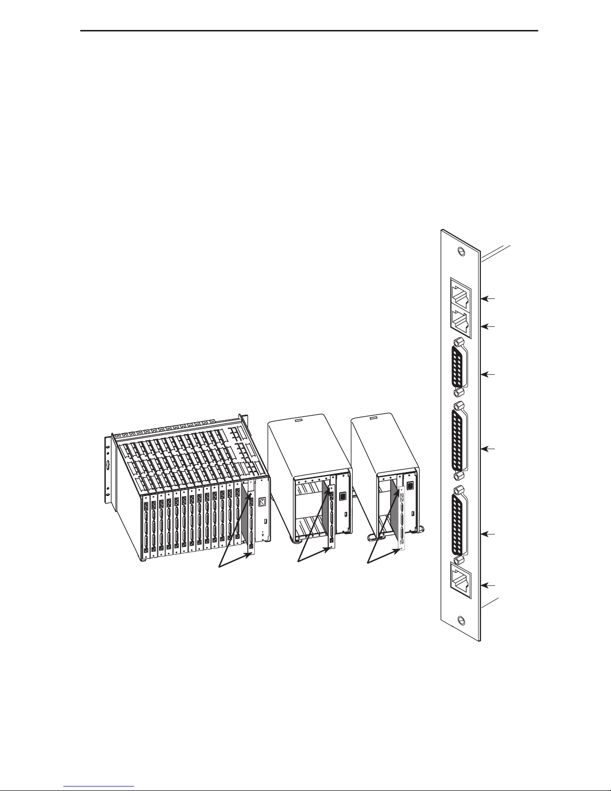
NAM
Rear Panel
SINGLE
T1 NAM
NET
DBM
DSX
PORT 1
PORT 2
COM
NET
DBM
(For
Future
Use)
DSX
Port 1
Port 2
COM
98-15050-03
4
Tools Required
A small Phillips screwdriver (#1 or #2) to install the T1 NAM
A small, flat-blade screwdriver to install the:
— I/O card
— Cable connections
Installing the I/O Card
The NAM’s I/O card provides the COM port, network, DSX and
DTE connections. The I/O card inserts directly behind the NAM
that it supports. Slot numbers are identical (in this case, Slot 01)
to facilitate correct installation.
1. Remove the I/O card from the shipping box. Handle only
by the top and bottom edges to avoid damaging the card.
2. At the rear of the housing, align the I/O card with the
upper and lower tracks of the slot. Push gently towards
the midplane until it stops and you cannot push the card
any further .
97-15748a
Screws
Rear View
Screws
2-Slot5-Slot
Screws
Access Carrier
3. There are two captive screws on the I/O card. Using a
screwdriver, alternately tighten each screw until the
screws are all the way in.
COM
SINGLE
T1 NAM
NET
DBM
DSX
PORT 1
PORT 2
Port 1
98-15054-02
DTE
Cable
DTE
Cable
V.35, RS-449,
V.11/X.21
Adapter Cable
DTE
DTE
Port 2
5
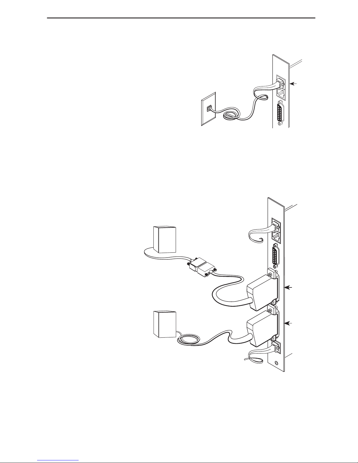
Connecting to the Network
1. Insert the 8-pin connector on the
RJ48C network cable into the NET
interface.
2. Insert the other end of the cable into
the RJ48C modular jack.
Connecting to a DTE
If the DTE cable type is
V.35, RS449, or V.11/X.21
(separately orderable):
1. Connect the plug to the
V.35, RS449, or V.11/X.21
end of the adapter
cable (as appropriate).
2. Connect the EIA 530A
end of the adapter cable
to PORT 1 or PORT 2.
If the DTE cable type is
EIA-530A:
1. Connect the EIA-530A
end of the DTE cable to
PORT 1 or PORT 2.
RJ48C
Jack
SINGLE
T1 NAM
NET
DBM
DSX
NET
98-15053-02
 Loading...