


 Loading...
Hotwire® 8620 GranDSLAM™
Installation Guide
Document No. 8620-A2-GN20-40
July 2003

Copyright © 2003 Paradyne Corporation.
All rights reserved.
Printed in U.S.A.
Notice
This publication is protected by federal copyright law. No part of this publication may be copied or distributed, transmitted, transcribed, stored in a retrieval system, or translated into any human or computer language in any form or by any means, electronic, mechanical, magnetic, manual or otherwise, or disclosed to third parties without the express written permission of Paradyne Corporation, 8545 126th Ave. N., Largo, FL 33773.
Paradyne Corporation makes no representation or warranties with respect to the contents hereof and specifically disclaims any implied warranties of merchantability or fitness for a particular purpose. Further, Paradyne Corporation reserves the right to revise this publication and to make changes from time to time in the contents hereof without obligation of Paradyne Corporation to notify any person of such revision or changes.
Changes and enhancements to the product and to the information herein will be documented and issued as a new release to this manual.
Warranty, Sales, Service, and Training Information
Contact your local sales representative, service representative, or distributor directly for any help needed. For additional information concerning warranty, sales, service, repair, installation, documentation, training, distributor locations, or Paradyne worldwide office locations, use one of the following methods:
Internet: Visit the Paradyne World Wide Web site at www.paradyne.com. (Be sure to register your warranty at www.paradyne.com/warranty.)
Telephone: Call our automated system to receive current information by fax or to speak with a company representative.
—Within the U.S.A., call 1-800-870-2221
—Outside the U.S.A., call 1-727-530-2340
Document Feedback
We welcome your comments and suggestions about this document. Please mail them to Technical Publications, Paradyne Corporation, 8545 126th Ave. N., Largo, FL 33773, or send e-mail to userdoc@paradyne.com. Include the number and title of this document in your correspondence. Please include your name and phone number if you are willing to provide additional clarification.
Trademarks
ACCULINK, COMSPHERE, FrameSaver, Hotwire, MVL, NextEDGE, OpenLane, and Performance Wizard are registered trademarks of Paradyne Corporation. GranDSLAM, GrandVIEW, iMarc, ReachDSL, and TruePut are trademarks of Paradyne Corporation. All other products and services mentioned herein are the trademarks, service marks, registered trademarks, or registered service marks of their respective owners.
A |
July 2003 |
8620-A2-GN20-40 |

! Important Safety Instructions
1.Read and follow all warning notices and instructions marked on the product or included in the manual.
2.The AC product version is intended to be used with a 3-wire grounding type plug — a plug which has a grounding pin. This is a safety feature. Equipment grounding is vital to ensure safe operation. Do not defeat the purpose of the grounding type plug by modifying the plug or using an adapter.
Prior to installation, use an outlet tester or a voltmeter to check the AC receptacle for the presence of earth ground. If the receptacle is not properly grounded, the installation must not continue until a qualified electrician has corrected the problem.
If a 3-wire grounding type power source is not available, consult a qualified electrician to determine another method of grounding the equipment.
3.Slots and openings in the cabinet are provided for ventilation. To ensure reliable operation of the product and to protect it from overheating, these slots and openings must not be blocked or covered.
4.Do not allow anything to rest on the power cord and do not locate the product where persons will walk on the power cord.
5.Do not attempt to service this product yourself, as opening or removing covers may expose you to dangerous high voltage points or other risks. Refer all servicing to qualified service personnel.
6.General purpose cables are provided with this product. Special cables, which may be required by the regulatory inspection authority for the installation site, are the responsibility of the customer. To reduce the risk of fire, use a UL Listed or CSA Certified, minimum No. 26 AWG telecommunication cable.
7.When installed in the final configuration, the product must comply with the applicable Safety Standards and regulatory requirements of the country in which it is installed. If necessary, consult with the appropriate regulatory agencies and inspection authorities to ensure compliance.
8.A rare phenomenon can create a voltage potential between the earth grounds of two or more buildings. If products installed in separate buildings are interconnected, the voltage potential may cause a hazardous condition. Consult a qualified electrical consultant to determine whether or not this phenomenon exists and, if necessary, implement corrective action prior to interconnecting the products.
9.Input power to the DC configuration of this product must be obtained from a SELV (Safety Extra Low Voltage) source (less than 60 VDC, and double insulate from hazardous voltages).
10.If it becomes necessary to replace either of the accessible A or B fuses (located on the front panel): For continued protection against fire and/or shock, replace the fuse with the same rating, manufacturer, and manufacturer’s part number as originally installed in the unit. These fuses are readily available through your local Paradyne distributor, or you may order replacement fuses by contacting Paradyne directly.
11.When powered by –48 VDC, this product may only be used in a Restricted Access Location in accordance with articles 110-16, 110-16, 110-17, and 110-18 of the National Electric Code, ANSI/NFPA 70. A Restricted Access Location is a secure area (dedicated equipment rooms, equipment closets, or the like) for equipment where access can only be gained by service personnel or by users who have been instructed about the reasons for the restrictions applied to the location and about any precautions that must be taken. In addition, access into this designated secured area is possible only through the use of a tool or lock and key, or other means of security, and is controlled by the authority responsible for the location.
—For DC operation: Connect the 48 VDC SELV supply source that is electrically isolated from the AC source. The 48 VDC source is to be reliably connected to earth. Connect the earthing (grounding) lug terminal located on the back of the 8620 GranDSLAM chassis.
—For DC operation: A readily accessible disconnect device as part of the building installation shall be incorporated in fixed wiring. The disconnect device (a 48 VDC 15–20A circuit breaker or switch) must be
included with a 15–20A, 48 VDC fuse or circuit breaker in the ungrounded connector. Use a minimum 14–18 AWG or 2.5 mm2 fixed power source wires with strain retention.
8620-A2-GN20-40 |
July 2003 |
B |

12.In addition, if the equipment is to be used with telecommunications circuits, take the following precautions:
—Never install telephone wiring during a lightning storm.
—Never install telephone jacks in wet locations unless the jack is specifically designed for wet locations.
—Never touch uninsulated telephone wires or terminals unless the telephone line has been disconnected at the network interface.
—Use caution when installing or modifying telephone lines.
—Avoid using a telephone (other than a cordless type) during an electrical storm. There may be a remote risk of electric shock from lightning.
—Do not use the telephone to report a gas leak in the vicinity of the leak.
! UNITED STATES – EMI NOTICE:
This equipment has been tested and found to comply with the limits for a Class A digital device, pursuant to Part 15 of the FCC rules. These limits are designed to provide reasonable protection against harmful interference when the equipment is operated in a commercial environment. This equipment generates, uses, and can radiate radio frequency energy and, if not installed and used in accordance with the instruction manual, may cause harmful interference to radio communications. Operation of this equipment in a residential area is likely to cause harmful interference in which case the user will be required to correct the interference at his own expense.
The authority to operate this equipment is conditioned by the requirements that no modifications will be made to the equipment unless the changes or modifications are expressly approved by Paradyne Corporation.
! CANADA – EMI NOTICE:
This Class A digital apparatus meets all requirements of the Canadian interference-causing equipment regulations.
Cet appareil numérique de la classe A respecte toutes les exigences du règlement sur le matériel brouilleur du Canada.
C |
July 2003 |
8620-A2-GN20-40 |
Notice to Users of the Canadian Telephone Network
The Industry Canada label identifies certified equipment. This certification means that the equipment meets telecommunications network protective, operational and safety requirements as prescribed in the appropriate Terminal Equipment Technical Requirements document(s). The Department does not guarantee the equipment will operate to the user’s satisfaction.
Before installing this equipment, users should ensure that it is permissible to be connected to the facilities of the local telecommunications company. The equipment must also be installed using an acceptable method of connection. The customer should be aware that compliance with the above conditions may not prevent degradation of service in some situations.
Repairs to certified equipment should be coordinated by a representative designated by the supplier. Any repairs or alterations made by the user to this equipment, or equipment malfunctions, may give the telecommunications company cause to request to disconnect the equipment.
Users should ensure for their own protection that the electrical ground connections of the power utility, telephone lines and internal metallic water pipe system, if present, are connected together. This precaution may be particularly important in rural areas.
CAUTION:
Users should not attempt to make such connections themselves, but should contact the appropriate electric inspection authority, or electrician, as appropriate.
The Ringer Equivalence Number (REN) assigned to each terminal device provides an indication of the maximum number of terminals allowed to be connected to a telephone interface. The termination on an interface may consist of any combination of devices subject only to the requirement that the sum of the Ringer Equivalence Numbers of all the devices does not exceed 5.
CE Marking
When the product is marked with the CE mark on the equipment label, a supporting Declaration of Conformity may be downloaded from the Paradyne World Wide Web site at www.paradyne.com. Select Library → Technical Manuals → CE Declarations of Conformity.
Japan
Class A ITE
This is a Class A product based on the standard of the Voluntary Control Council for interference by Information Technology Equipment (VCCI). If this equipment is used in a domestic environment, radio disturbance may arise. When such trouble occurs, the user may be required to take corrective actions.
8620-A2-GN20-40 |
July 2003 |
D |

E |
July 2003 |
8620-A2-GN20-40 |

Contents
About This Guide
ν Document Purpose and Intended Audience . . . . . . . . . . . . . . . . . . . . |
iii |
|
ν New Features for this Release. . . . . . . . . . . . . . . . . . . . . . . . . . . . . . . |
iii |
|
ν |
Document Summary . . . . . . . . . . . . . . . . . . . . . . . . . . . . . . . . . . . . . . |
iii |
ν |
Product-Related Documents . . . . . . . . . . . . . . . . . . . . . . . . . . . . . . . . |
iv |
1 Introduction
ν |
The Hotwire 8620 GranDSLAM . . . . . . . . . . . . . . . . . . . . . . . . . . . . . . |
1-1 |
|
|
Hotwire 8620 |
GranDSLAM Cards . . . . . . . . . . . . . . . . . . . . . . . . . |
1-2 |
ν |
Hotwire 8620 GranDSLAM Features . . . . . . . . . . . . . . . . . . . . . . . . . . |
1-4 |
|
|
Hotwire 8620 |
GranDSLAM Components. . . . . . . . . . . . . . . . . . . . |
1-5 |
2 Installation
ν |
Preinstallation Considerations . . . . . . . . . . . . . . . . . . . . . . . . . . . . . . . |
2-1 |
ν |
Unpacking the Hardware . . . . . . . . . . . . . . . . . . . . . . . . . . . . . . . . . . . |
2-3 |
ν |
Package Contents . . . . . . . . . . . . . . . . . . . . . . . . . . . . . . . . . . . . . . . . |
2-3 |
ν |
Mounting Configurations . . . . . . . . . . . . . . . . . . . . . . . . . . . . . . . . . . . |
2-4 |
ν Hotwire 8620 GranDSLAM Chassis Installation. . . . . . . . . . . . . . . . . . |
2-5 |
|
|
Placing the 8620 Chassis on a Desktop or Table . . . . . . . . . . . . . |
2-5 |
|
Rack Mounting the 8620 Chassis . . . . . . . . . . . . . . . . . . . . . . . . . |
2-6 |
|
Attaching the Mounting Brackets . . . . . . . . . . . . . . . . . . . . . . . . . . |
2-6 |
|
Installing the 8620 Chassis in a Rack . . . . . . . . . . . . . . . . . . . . . . |
2-7 |
ν |
Complying with NEBS . . . . . . . . . . . . . . . . . . . . . . . . . . . . . . . . . . . . . |
2-8 |
|
Connection to the CO Ground Lug . . . . . . . . . . . . . . . . . . . . . . . . |
2-8 |
|
ESD Wrist Strap Jack . . . . . . . . . . . . . . . . . . . . . . . . . . . . . . . . . . |
2-8 |
ν |
Connecting Power . . . . . . . . . . . . . . . . . . . . . . . . . . . . . . . . . . . . . . . . |
2-9 |
|
Using a Single DC Power Source . . . . . . . . . . . . . . . . . . . . . . . . . |
2-10 |
|
Using Two DC Power Sources for Power Redundancy. . . . . . . . . |
2-11 |
|
Using Only AC Power Source . . . . . . . . . . . . . . . . . . . . . . . . . . . . |
2-12 |
|
Using AC Power with DC Power Backup. . . . . . . . . . . . . . . . . . . . |
2-13 |
ν |
Installing the Cards . . . . . . . . . . . . . . . . . . . . . . . . . . . . . . . . . . . . . . . |
2-14 |
ν |
Verifying the Installation . . . . . . . . . . . . . . . . . . . . . . . . . . . . . . . . . . . . |
2-16 |
8620-A2-GN20-40 |
July 2003 |
i |

Contents
3 Cabling
ν Making Cable Connections . . . . . . . . . . . . . . . . . . . . . . . . . . . . . . . . . 3-1
ν Installing Network Tip and Ring Connections . . . . . . . . . . . . . . . . . . . 3-2 Connecting a DSL Card Using Cable Ties . . . . . . . . . . . . . . . . . . 3-3 Connecting a DSL Card Using Locking Pivot Brackets . . . . . . . . . 3-4
ν Connecting an SCP Card to a Terminal or PC . . . . . . . . . . . . . . . . . . 3-5
ν Connecting an SCP Card to an SNMP Management System . . . . . . . 3-6
ν Connecting an MCP Card to a Terminal or PC . . . . . . . . . . . . . . . . . . 3-6
ν Connecting to a Modem for Remote Management (with MCP) . . . . . . 3-7
ν Connecting an MCP to an SNMP Management System . . . . . . . . . . . 3-8
ν Connecting CO Alarm to the Alarm System. . . . . . . . . . . . . . . . . . . . . 3-9
4 Troubleshooting
ν |
Troubleshooting Table . . . . . . . . . . . . . . . . . . . . . . . . . . . . . . . . . . . . . |
4-1 |
ν |
LEDs . . . . . . . . . . . . . . . . . . . . . . . . . . . . . . . . . . . . . . . . . . . . . . . . . . |
4-3 |
A Pinouts
ν 8-Pin Modular Connector for Alarm Relay Interface . . . . . . . . . . . . . . |
A-1 |
|
ν 8-Pin Modular LAN MCP/LAN SCM Slot Connector . . . . . . . . . . . . . . |
A-2 |
|
ν 8-Pin Modular Serial SCM Connector . . . . . . . . . . . . . . . . . . . . . . . . . |
A-2 |
|
ν 8-Pin Modular Serial MCP Connector . . . . . . . . . . . . . . . . . . . . . . . . . |
A-3 |
|
ν |
DB25 Adapter Pinouts . . . . . . . . . . . . . . . . . . . . . . . . . . . . . . . . . . . . . |
A-4 |
ν |
DB9 Adapter Pinouts . . . . . . . . . . . . . . . . . . . . . . . . . . . . . . . . . . . . . . |
A-4 |
ν Telco 50-Pin Connector Pinouts for DSL Loops and POTS Splitters. . |
A-5 |
|
BTechnical Specifications Index
ii |
July 2003 |
8620-A2-GN20-40 |

About This Guide
Document Purpose and Intended Audience
This guide is written for administrators and technicians who install devices at the central office (CO) or at a Network Service Provider (NSP) location adjacent to the CO. It should be used in conjunction with the appropriate Hotwire DSL Card User’s Guide.
To install the customer premises portion of the Hotwire 8620 GranDSLAM, refer to the appropriate Hotwire Remote Termination Unit (RTU) Customer Premises Installation Instructions and Hotwire POTS Splitter Customer Premises Installation Instructions.
New Features for this Release
This version of the Hotwire 8620 GranDSLAM Installation Guide includes the Models 8412, 8413, 8414, 8416, and 8417 Shelf Concentration and Processing (SCP) card, and the Models 8955, 8965, and 8985 ATM line cards.
Document Summary
Section |
Description |
|
|
Chapter 1, Introduction |
Provides general information about what types of cards |
|
can be used in the Hotwire 8620 GranDSLAM and |
|
GranDSLAM features. |
|
|
Chapter 2, Installation |
Describes what is supplied with the Hotwire 8620 |
|
GranDSLAM, how to install it, and how to install cards into |
|
the chassis. |
|
|
Chapter 3, Cabling |
Describes how to install various cables used by the |
|
Hotwire 8620 GranDSLAM and its cards. |
|
|
Chapter 4, Troubleshooting |
Lists suggested solutions to possible GranDSLAM |
|
problems and describes the GranDSLAM LEDs. |
|
|
Appendix A, Pinouts |
Provides pinouts for the GranDSLAM connectors as well |
|
as for connectors on cards that can be used in the |
|
GranDSLAM chassis. |
|
|
8620-A2-GN20-40 |
July 2003 |
iii |

About This Guide
Section |
Description |
|
|
Appendix B, Technical |
Lists Technical Specifications for the Hotwire 8620 |
Specifications |
GranDSLAM. |
|
|
Glossary |
Defines terms and acronyms used in this document. |
|
|
Index |
Lists key terms, concepts, and sections in alphabetical |
|
order. |
|
|
A master glossary of terms and acronyms used in Paradyne documents is available online at www.paradyne.com. Select Support → Technical Manuals → Technical Glossary.
Product-Related Documents
Complete documentation for this product is available online at
www.paradyne.com. Select Support → Technical Manuals → Hotwire DSL
Systems.
Document Number |
Document Title |
|
|
6050-A2-GZ40 |
Hotwire Central Office Universal POTS Splitter, Models 6050 |
|
and 7020, Installation Instructions |
|
|
8000-A2-GB22 |
Hotwire Management Communications (MCC) Card, IP |
|
Conservative, User’s Guide |
|
|
8000-A2-GB26 |
Hotwire MVL, ReachDSL, RADSL, IDSL, and SDSL Cards, |
|
Models 8310, 8312/8314, 8510/8373/8374, 8323/8324, and |
|
8343/8344, User’s Guide |
|
|
8000-A2-GZ40 |
Hotwire MCC Card, IP Conservative, Installation Instructions |
|
|
8021-A2-GB20 |
Hotwire Shelf Concentration Module (SCM) Card User’s Guide |
|
|
8021-A2-GZ40 |
Hotwire Shelf Concentration Module (SCM) Card Installation |
|
Instructions |
|
|
8303-A2-GZ40 |
Hotwire 8303/8304 IDSL Cards Installation Instructions |
|
|
8312-A2-GZ40 |
Hotwire 8312/8314 MVL and ReachDSL/MVL Cards Installation |
|
Instructions |
|
|
8335-A2-GB20 |
Hotwire ATM Line Cards, Models 8335, 8355, 8365, and 8385, |
|
User’s Guide |
|
|
8335-A2-GZ40 |
Hotwire ATM Line Cards, Models 8335, 8355, 8365, and 8385, |
|
Installation Instructions |
|
|
8343-A2-GZ40 |
Hotwire 8343/8344 Packet SDSL Cards Installation Instructions |
|
|
8373-A2-GZ40 |
Hotwire 8373/8374 RADSL Cards Installation Instructions |
|
|
8400-A2-GB20 |
Hotwire Shelf Concentration and Processing (SCP) Card User’s |
|
Guide |
|
|
8400-A2-GZ40 |
Hotwire Shelf Concentration and Processing (SCP) Card |
|
Installation Instructions |
|
|
iv |
July 2003 |
8620-A2-GN20-40 |
About This Guide
Document Number |
Document Title |
|
|
8700-A2-GB20 |
Hotwire TDM SDSL Termination Units, Models 8777 and 8779, |
|
User’s Guide |
|
|
8700-A2-GN10 |
Hotwire TDM SDSL Termination Units, Models 8777 and 8779, |
|
Installation Instructions |
|
|
8700-A2-GN15 |
Hotwire TDM SDSL Termination Units, Models 8775 and 8785, |
|
Installation Instructions |
|
|
8774-A2-GB20 |
Hotwire 8774 TDM SDSL Termination Unit, with DSX-1 |
|
Interface, User’s Guide |
|
|
8774-A2-GZ40 |
Hotwire 8774 TDM SDSL Termination Unit, with DSX-1 |
|
Interface, Installation Instructions |
|
|
8776-A2-GB20 |
Hotwire 8776 TDM SDSL Termination Unit, with G.703 Interface, |
|
User’s Guide |
|
|
8776-A2-GZ40 |
Hotwire 8776 TDM SDSL Termination Unit, with G.703 Interface, |
|
Installation Instructions |
|
|
8784-A2-GB20 |
Hotwire 8784 TDM SDSL Termination Unit, with DSX-1 |
|
Interface, User’s Guide |
|
|
8784-A2-GZ40 |
Hotwire 8784 TDM SDSL Termination Unit, with DSX-1 |
|
Interface, Installation Instructions |
|
|
8786-A2-GB20 |
Hotwire 8786 TDM SDSL Termination Unit, with G.703 Interface, |
|
User’s Guide |
|
|
8786-A2-GZ40 |
Hotwire 8786 TDM SDSL Termination Unit, with G.703 Interface, |
|
Installation Instructions |
|
|
8799-A2-GB20 |
Hotwire 8799 TDM SHDSL Line Card, with G.703 Interface, |
|
User’s Guide |
|
|
8799-A2-GZ40 |
Hotwire 8799 TDM SHDSL Line Card, with G.703 Interface, |
|
Installation Instructions |
|
|
8900-A2-GB20 |
Hotwire ATM Line Cards, Models 8955, 8965, and 8985, User’s |
|
Guide |
|
|
8900-A2-GZ40 |
Hotwire ATM Line Cards, Models 8955, 8965, and 8985, |
|
Installation Instructions |
|
|
To order a paper copy of a Paradyne document, or to speak with a sales representative, please call 727-530-2000.
8620-A2-GN20-40 |
July 2003 |
v |

About This Guide
vi |
July 2003 |
8620-A2-GN20-40 |

Introduction
1
The Hotwire 8620 GranDSLAM
The Hotwire® 8620 GranDSLAM™, which is designed to be installed in an Internet Service Provider (ISP) or Network Access Provider (NAP) location, is a low-startup-cost alternative chassis to the Hotwire 8820 GranDSLAM chassis. The 8620 GranDSLAM can also be placed in a Remote Terminal (RT) adjacent to the Telco’s Digital Loop Carrier (DLC) systems. It provides high-speed Internet or intranet access.
The System Interface Module (SIM) is shipped with the chassis already installed in the bottom slot. The SIM provides user interface connections on the front of the GranDSLAM.
An Asynchronous Transfer Mode (ATM) backplane provides ATM aggregation across multiple DSL port cards.
With Release 3.0 of the GranDSLAM, there are two configurations:
νSCM-based. A Management Control Processor (MCP) card is installed in Slot 1 for management of the DSL cards. A Shelf Concentration Module (SCM), installed in Slot A, provides aggregation of DSL traffic for the chassis. The chassis supports up to two DSL cards and 48 ports.
νSCP-card-based. A Shelf Concentration and Processing (SCP) card is installed in Slot A to provide the management functions of the MCP and the aggregation functions of the SCM. The chassis supports up to three DSL cards and 72 ports.
The SCP card supports Models 8955, 8965, and 8985 ATM line cards. With an MCP installed, legacy TDM cards (Models 8775, 8777, 8779, and 8799) are also supported.
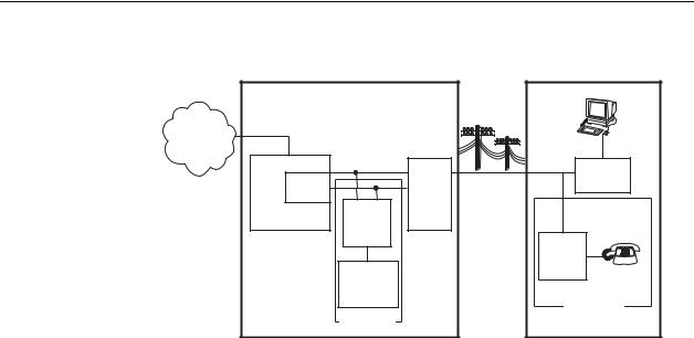
The following illustration shows a high-level view of a typical Hotwire configuration.
8620-A2-GN20-40 |
July 2003 |
1-1 |
1. Introduction
Central Office (CO) |
Customer Premises (CP) |
|
|
|
|
Data |
|
|
|
|
|
Interface |
|
Network |
|
|
|
|
|
Service |
ATM |
|
|
|
|
Provider |
SCP Card |
|
|
|
|
|
|
|
SN |
||
|
DSL |
|
POTS/DSL |
||
|
|
|
|
||
|
Card |
CO |
MDF |
|
|
|
GranDSLAM |
|
POTS |
Voice |
|
|
|
POTS |
|
|
|
|
|
Splitter |
|
Interface |
|
|
|
|
|
CP |
|
|
|
|
|
POTS |
|
|
|
Switched |
|
Splitter |
|
|
|
|
|
|
|
|
|
Network |
|
|
|
|
|
Optional |
|
Optional |
|
|
|
|
|
|
|
Legend: DSL – Digital Subscriber Line |
SN – Service Node |
MDF – Main Distribution Frame |
POTS – Plain Old Telephone Service |
03-17428
Hotwire 8620 GranDSLAM Cards
The GranDSLAM chassis accepts the following types of cards:
νSCP card
Provides aggregation of DSL traffic on the ATM bus for the shelf, and administers and provides diagnostic connectivity to the DSL cards. The SCP
card acts as a mid-level manager and works in conjunction with an SNMP network management system, such as OpenLane®, via its LAN port or inband management channel. It gathers operational status for each of the DSL cards and responds to the SNMP requests. The card also has a serial port for local terminal access. The SCP is designed as a replacement for both the MCP card and the SCM card.
νMCP card
Administers and provides diagnostic connectivity to the DSL cards. The MCP
acts as a mid-level manager and works in conjunction with an SNMP network management system, such as OpenLane®, via its LAN port or inband management channel. It gathers operational status for each of the DSL cards and responds to the SNMP requests. The card also has a serial port for local terminal access.
νSCM card
Provides aggregation of DSL traffic on the ATM bus for the shelf.
1-2 |
July 2003 |
8620-A2-GN20-40 |

1. Introduction
νDSL cards
Provide a processor and an Ethernet or ATM interface to the NSP. The processor controls the modems and forwards the packet traffic to and from the Ethernet, ATM and DSL interfaces. Models include:
—8303 24-port Integrated Services Digital Network (ISDN) Digital Subscriber Line (IDSL) card that interoperates with the 6301 and 6302 IDSL Routers.
—8304 24-port Packet IDSL 2B1Q card with ATM uplink that interoperates with the 6301 and 6302 IDSL Routers.
—8312 12-port ReachDSL cards that interoperate with the Hotwire 6310 and 6350 ReachDSL modems.
—8314 12-port ReachDSL card that interoperates with the Hotwire 6310 and 6350 ReachDSL modem.
—8335 16-port ATM SDSL card.
—8343 24-port Packet Symmetric Digital Subscriber Line (Packet SDSL) CAP (Carrierless Amplitude and Phase Modulation) card that interoperates with the 6341 and 6342 SDSL Routers.
—8344 24-port Packet SDSL CAP card with ATM uplink that interoperates with the 6341 and 6342 SDSL Routers.
—8355 24-port ReachDSL card that interoperates with the Hotwire 6390 ReachDSL modem.
—8365 12-port ATM Asymmetric Digital Subscriber Line (ADSL) card.
—8373 12-port Rate Adaptive Digital Subscriber Line (RADSL) card that interoperates with the 5620 Remote Termination Unit (RTU) or the 6371 RADSL Router.
—8374 12-port RADSL card with ATM uplink that interoperates with the 6371 RADSL Router.
—8385 24-port ATM Symmetric High-bit-rate Digital Subscriber Line (SHDSL) card.
—8777 and 8779 8-port TDM SDSL cards that interoperate with the Hotwire 7974, 7975, and 7976 TDM SDSL Standalone Termination Units.
—8799 8-port TDM SHDSL card that interoperates with the Hotwire 7995 and 7996 TDM SHDSL Endpoints.
—8955 24-port ReachDSL card that interoperates with the Hotwire 6390 ReachDSL modem, for use with the SCP card.
—8965 24-port ATM ADSL card, for use with the SCP card.
—8985 24-port ATM SHDSL card, for use with the SCP card.
RADSL, ReachDSL, IDSL, SDSL, ATM SDSL, ATM ADSL, TDM SDSL, and TDM SHDSL cards are generically referred to as DSL cards or line cards in this document.
8620-A2-GN20-40 |
July 2003 |
1-3 |

1. Introduction
Table 1-1 shows which DSL cards can be used with the different SCP card, MCP, and SCM configurations.
Table 1-1. DSL Card Interoperability
SCP Card |
SCP Card and MCP |
SCM and MCP |
|
|
|
8955 |
8775 |
8303 |
8965 |
8777 |
8304 |
8985 |
8779 |
8312 |
|
8799 |
8314 |
|
|
8335 |
|
|
8343 |
|
|
8344 |
|
|
8355 |
|
|
8365 |
|
|
8373 |
|
|
8374 |
|
|
8385 |
|
|
8777 |
|
|
8779 |
|
|
8799 |
|
|
|
Hotwire 8620 GranDSLAM Features
The Hotwire 8620 GranDSLAM chassis has the following features:
νAC and DC Powered Models
Two versions of the Hotwire 8620 GranDSLAM chassis are available:
—AC powered. The AC version will operate from 100 to 240 volts AC (nominal), 50 to 60 Hz. It can also be connected to a DC source to provide power redundancy.
—DC powered. The DC version requires a source of 48 VDC. When using the DC version, two separate DC sources may be employed to provide power redundancy. If one power source fails, the other source provides all of the power needed by the system. This is done automatically without system disruption.
νHot Swappable Cards
The MCP and DSL cards can be installed and removed from the Hotwire 8620 GranDSLAM chassis without service disruption. You can replace these cards without powering down the chassis and disrupting service to the other cards. Removing the SCM card disrupts traffic on DSL port cards.
νPrimary Network Management Support via SNMP
SNMP management of the DSL cards is accomplished over a single external Ethernet or inband management connection to the MCP card from a Network Management System (NMS) (such as Paradyne’s OpenLane). The MCP card gathers all management information for each of the DSL cards and responds to the SNMP requests on behalf of the cards.
For a list of specific management information bases (MIBs) supported, visit the Paradyne website www.paradyne.com. Select Support → Online Support → MIBs.
1-4 |
July 2003 |
8620-A2-GN20-40 |
1. Introduction
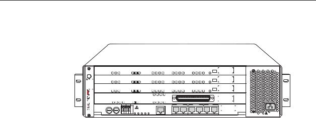
Hotwire 8620 GranDSLAM Components
ESD |
SYSTEM |
OK |
Alrm |
Test |
|
ATM |
BUS |
TX |
RX |
LOC |
|
|
DSL |
PORT1/13 |
2/14 |
3/15 |
4/16 |
PORT |
5/17 |
6/18 |
7/19 |
8/20 |
PORT |
9/21 |
10/22 11/23 12/24 |
ALT BANK |
13-24 |
1-12 |
G.DMT G.Lite |
8965 |
3 |
|||||
|
|
|
|
|
|
|
|
|
|
|
|
|
|
|
|
|
|
|
|
|
|
|
|
|
ALT BANK |
13-24 |
|
|
|
|
||||||
|
SYSTEM |
OK |
Alrm |
Test |
|
ATM |
BUS |
TX |
RX |
LOC |
|
|
DSL |
PORT1/13 |
2/14 |
3/15 |
4/16 |
PORT |
5/17 |
6/18 |
7/19 |
8/20 |
PORT |
9/21 |
10/22 11/23 |
12/24 |
1-12 |
G.DMT G.Lite |
8965 |
2 |
||||||
|
|
|
|
|
|
|
|
|
|
|
|
|
|
|
|
|
|
|
|
|
|
|
|
|
|
|||||||||||
|
|
|
|
|
|
|
|
|
|
|
|
|
|
|
|
|
|
|
|
|
|
|
|
|
ALT BANK |
13-24 |
|
|
|
|
||||||
|
SYSTEM |
OK |
Alrm |
Test |
|
ATM |
BUS |
TX |
RX |
LOC |
|
|
DSL |
PORT1/13 |
2/14 |
3/15 |
4/16 |
PORT |
5/17 |
6/18 |
7/19 |
8/20 |
PORT |
9/21 |
10/22 11/23 12/24 |
1-12 |
G.DMT G.Lite |
8965 |
1 |
|||||||
GranDSLAM 8620 |
|
|
|
|
|
|
|
|
|
|
|
|
|
|
|
|
|
|
|
|
|
|
|
|
|
|||||||||||
|
|
|
|
|
|
|
|
|
|
|
|
|
|
|
|
|
|
|
|
|
|
|
|
|
|
|
|
|
|
|||||||
SYSTEM |
Active StandbyAlarm Test |
ETHERNET |
TX |
RX |
|
|
|
UPLINK |
LK5 |
LK6 |
LK7 |
LK8 |
|
|
|
|
|
|
|
|
|
|
|
|
|
8417 |
A |
|||||||||
|
|
|
LK1 |
LK2 |
LK3 |
LK4 |
|
|
|
|
|
|
|
|
|
|
|
|
|
|
||||||||||||||||
|
|
|
|
|
|
|
|
|
|
|
|
|
|
|
|
|
|
|
|
|
|
|
|
|
||||||||||||
|
|
|
|
|
|
|
|
|
|
|
|
|
|
|
|
A CLOCK B |
|
SCM SERIAL MCP |
|
|
|
|
|
|
|
|||||||||||
DC FUSES |
|
-48V |
|
RTN |
|
|
|
|
|
ALARMS |
|
|
ALARM |
|
|
|
SCM |
LAN |
MCP |
SIM |
|
|||||||||||||||
A |
|
B |
|
|
|
|
|
|
|
|
|
|
|
M |
M |
|
|
|
|
|
|
|
|
|
|
|
|
|
|
|
|
SIM |
||||
|
|
|
|
|
|
|
|
|
|
|
DC |
|
F |
A |
|
I |
|
|
|
|
|
|
|
|
|
|
|
|
|
|
|
|
SCPIMA- |
|
||
|
|
|
|
|
|
|
|
|
|
|
|
J |
N |
|
|
|
|
|
|
|
|
|
|
|
|
|
|
|
|
|
|
|||||
|
|
|
|
|
|
|
|
|
|
POWER |
A |
O |
O |
|
|
|
|
|
|
|
|
|
|
|
|
|
|
|
|
|
|
|||||
|
|
|
|
|
|
|
|
|
|
|
|
A |
B |
N |
R |
R |
|
|
|
|
|
|
|
|
|
|
|
|
|
|
|
|
|
|
AC INPUT |
|
|
|
|
|
|
A |
B |
A |
B |
|
|
|
|
|
|
|
|
|
|
|
|
|
|
|
|
|
|
|
|
|
|
|
|
|
|
||
|
|
|
|
|
|
|
|
|
|
|
|
|
|
|
|
|
|
|
|
|
|
|
|
|
|
|
|
|
|
|
|
|
|
|
|
03-17429 |
The Hotwire 8620 GranDSLAM is a 4-slot chassis designed to house one of the following combinations:
νOne SCP card and up to three DSL cards
νOne SCP card, one MCP card, and up to two DSL cards
νOne MCP card, one SCM card, and up to two DSL cards.
Before installing the Hotwire 8620 GranDSLAM, read the Important Safety
Instructions located at the front of this document.
8620-A2-GN20-40 |
July 2003 |
1-5 |

1. Introduction
1-6 |
July 2003 |
8620-A2-GN20-40 |
Loading...