

Paradyne 9161 Installation Instructions Manual

TM
1
9161 Single T1 Network Access Module (NAM)
Installation Instructions
Document Number 9161-A2-GN10-20
September 1997
Before You Begin
Make sure you have:
An operable T1 network connection
An async (VT100-compatible) terminal emulation
Housing and other associated hardware
Applicable cables
Package Checklist
Verify that your package contains the following:
T1 NAM and associated I/O card
Affidavit Requirements for Connection to Digital Service
Warranty
Safety, Regulatory, Warranty and Service Information
(Document No. 9000-A2-GX41)
Available Options
The following option is separately orderable:
RJ48C modular cable for network access (14)

2
What Does a T1 NAM Do?
The T1 NAM acts as an interface between the T1 digital network and the customer
premises equipment, converting signals received from the DTE to bipolar signals that
can be transmitted over T1 and Fractional T1 lines. The T1 NAM also provides a
DSX-1 drop and insert port to allow DTEs supporting the DS1 signal format to share
the network T1 with other high-speed equipment, as well as two synchronous data
ports. Typical applications include:
H Wide Area Networks (WANs)
H Channel extension
H Video teleconferencing
Cables You May Need to Order
The following cables are specifically for this product. See page A of either the
Model 916x/926x T1 Access Mux User’s Guide
(Document No. 9161-A2-GB20) or the
Model 916x/926x T1 Access Mux Technical Reference
(Document No. 9161-A2-GH30)
for ordering information. You can also see the
Technical Reference
for cable pin-out
information.
If connecting to a . . . Order a . . .
PC (DB9 interface/connector –
EIA-232 connection)
COM Port-to-Terminal/Printer cable (14)
PC (DB9 interface/connector –
EIA-232 connection)
COM Port-to-PC cable (14)
DTE with a V.35
interface/connector
MS34 to DB25 adapter cable for each port: Port 1
and/or Port 2 (1′)
DTE with a RS-449
interface/connector
DB37 to DB25 DTE adapter cable for each port:
Port 1 and/or Port 2 (1′)
DTE with a V.11/X.21
interface/connector
DB15 to DB25 adapter cable for each port: Port 1
and/or Port 2 (1′)
LAN Adapter
COM Port-to-LAN Adapter cable (14)

3
Recommended Order of Installation
1. First, install the I/O card.
2. Connect all cables into the I/O card.
3. Install the NAM.
4. Go to the
2-Slot Housing Installation Instructions
(Document No. 9000-A2-GN15),
5-Slot Housing with AC Power Supply Installation Instructions
(Document
No. 9000-A2-GN16), or
5-Slot Housing with DC Power Supply Installation
Instructions
(Document No. 9000-A2-GN1C) for power-up verification procedures.
Tools Required
H A small Phillips screwdriver (#1 or #2) to install the T1 NAM
H A small, flat-blade screwdriver to install the:
— I/O card
— Cable connections
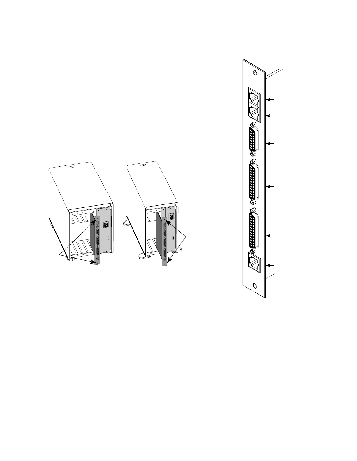
NAM
Rear Panel
9161
NET
DBM
DSX
PORT 1
PORT 2
COM
NET
DBM
(For
Future
Use)
DSX
Port 1
Port 2
COM
97-15050-01
4
Installing the I/O Card
The NAM’s I/O card provides the COM port, network, DSX and
DTE connections. The I/O card inserts directly behind the NAM
that it supports. Slot numbers are identical (in this case, Slot 01)
to facilitate correct installation.
1. Remove the I/O card from the shipping box. Handle only
by the top and bottom edges to avoid damaging the card.
2. At the rear of the housing, align the I/O card with the
upper and lower tracks of the slot. Push gently towards
the midplane until it stops and you cannot push the card
any further .
496-15155
Screws
Rear View
Screws
5-Slot 2-Slot
3. There are two captive screws on the I/O card. Using a
screwdriver, alternately tighten each screw until the
screws are all the way in.
COM
9161
NET
DBM
DSX
PORT 1
PORT 2
Port 1
496-15054
DTE
Cable
DTE
Cable
V.35, RS-449,
V.11/X.21
Adapter Cable
DTE
DTE
Port 2
5
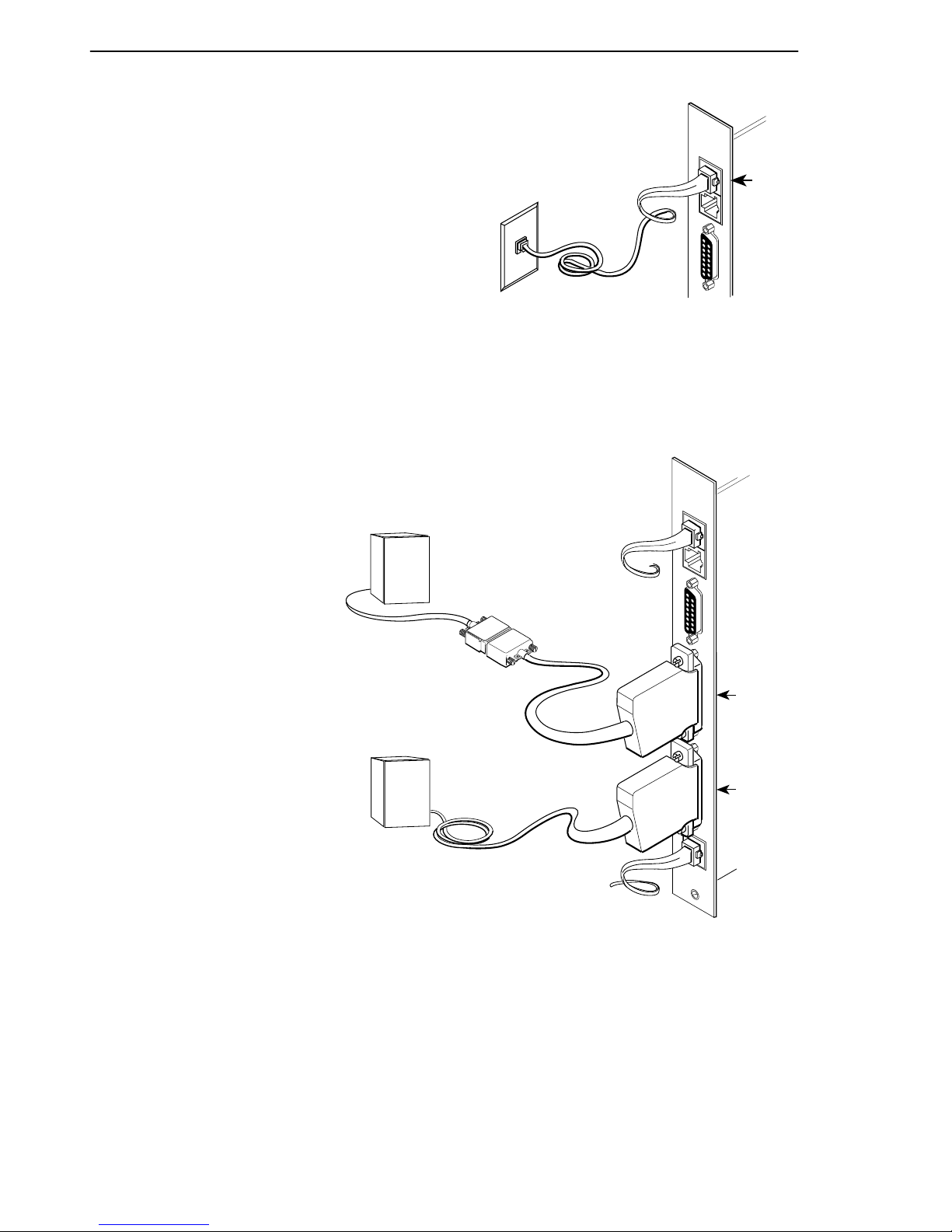
Connecting to the Network
1. Insert the 8-pin connector on the
RJ48C network cable into the NET
interface.
2. Insert the other end of the cable into
the RJ48C modular jack.
Connecting to a DTE
If the DTE cable type is
V.35, RS449, or V.11/X.21
(separately orderable):
1. Connect the plug to the
V.35, RS449, or V.11/X.21
end of the adapter
cable (as appropriate).
2. Connect the EIA 530A
end of the adapter cable
to PORT 1 or PORT 2.
If the DTE cable type is
EIA 530A:
1. Connect the EIA-530A
end of the DTE cable to
PORT 1 or PORT 2.
RJ48C
Jack
9161
NET
DBM
DSX
NET
496-15053
 Loading...