

Page 1

TM
5-Slot Housing and
FrameSaver 9000 Series Access Carrier
AC Power Supply
Installation Instructions
Document Number 9000-A2-GN17-30
August 1998
Before You Begin
Both the 5-slot housing and the FrameSaver 9000 Series Access Carrier can hold up to
two power supplies. A second redundant power supply provides backup for the first.
Before you start your installation, be sure to review the following information.
CAUTION:
Refer installation of power supplies to qualified service personnel.
!
HANDLING PRECAUTIONS FOR ST ATIC-SENSITIVE DEVICES
This product is designed to protect sensitive components from
damage due to electrostatic discharge (ESD) during normal
operation. When performing installation procedures,
however, take proper static control precautions to
prevent damage to equipment. If you are not sure
of the proper static control precautions, contact
your nearest sales or service representative.
496-15149
Package Contents
Verify that your package contains an ac power supply (see following specifications).
1
Page 2
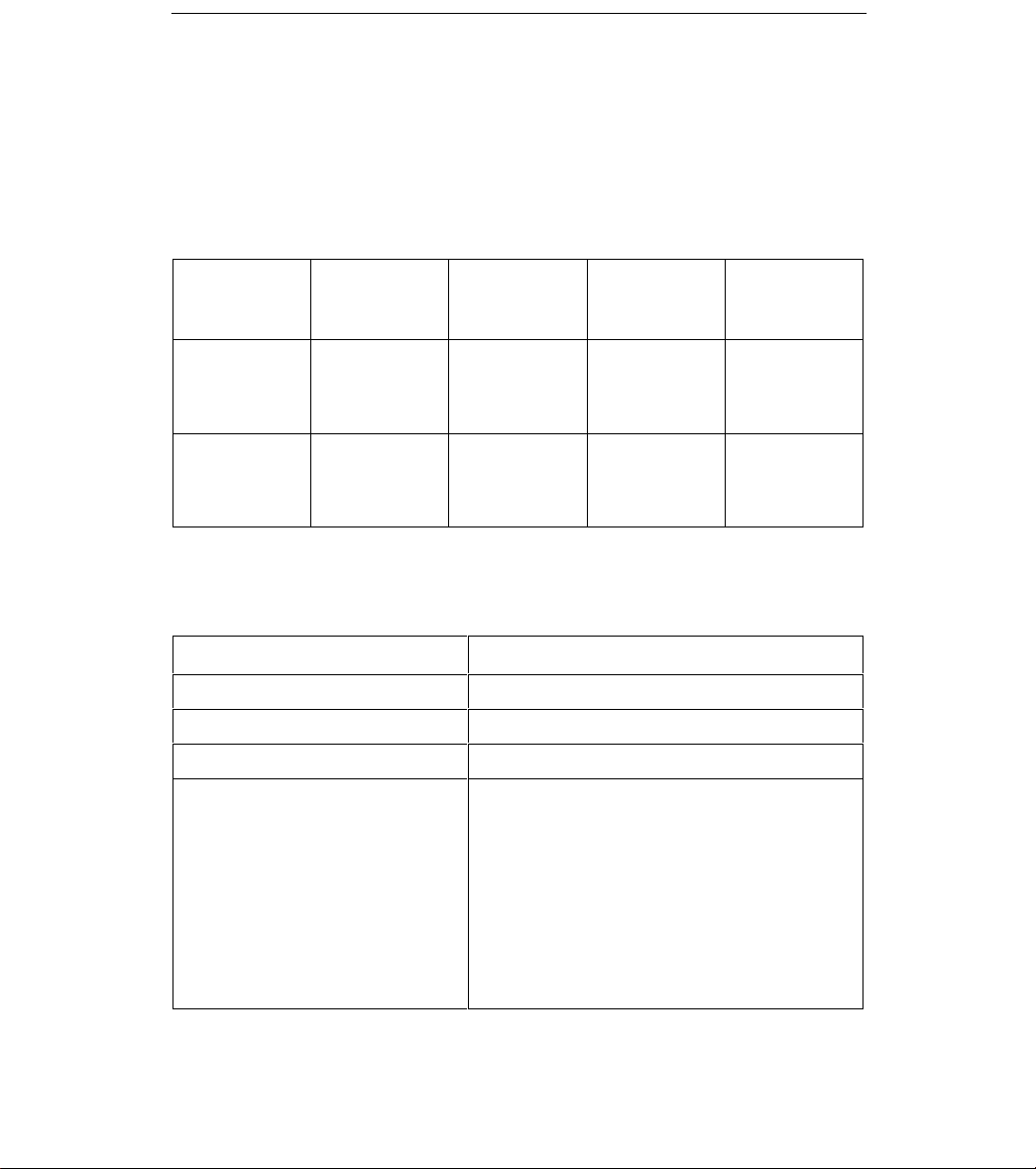
Do I Have the Correct Power Supply?
p
The following ac power supplies are available. Make sure that you have the correct one
for your housing and application.
NOTE:
The 120 V ac power supply has a label to warn you to connect the supply only to a
100–120 Vac power source.
For
Name/Feature
Number
Wattage/Volts
Fits in This
Housing
Keyed?
International
Use?
120 V ac Power
Supply
(Feature No.
9005-F1-020)
Universal
Power Supply
(Feature No.
9007-F1-040)
60 watts,
100–120 V ac
70 watts,
100–240 V ac
5-slot only No No
Access Carrier
only
Yes (see figure
on page 3)
Yes
Technical Specifications for 120 Vac Power Supply in 5-Slot Housing
Specification Criteria
Rated Nominal Voltage 100–120 Vac, 50/60 Hz
Operating Voltage Range 85–132 Vac, 50/60 Hz
Rated Current 1.5 Amps
Power Consumption (typical)
1 power supply installed
2 power supplies installed
120 Vac 60 Hz 1.03 amps 60 watts
100 Vac 50 Hz 1.15 amps 60 watts
Result: 207 Btu per hour
120 Vac 60 Hz 1.13 amps 64.5 watts
100 Vac 50 Hz 1.25 amps 64.5 watts
Result: 221 Btu per hour
2
Page 3

Universal Power Supply
Keyed
Front Rear
97-15746
Technical Specifications for Universal Power Supply in Access Carrier
Specification Criteria
Rated Nominal Voltage 100–240 Vac, 50/60 Hz
Operating Voltage Range 85–265 Vac, 50/60 Hz
Rated Current 4.0 amps
Power Consumption (typical)
1 power supply installed
2 power supplies installed
100 Vac 60 Hz 1.7 amps 171 watts
120 Vac 60 Hz 1.4 amps 171 watts
230 Vac 50 Hz 0.8 amps 167 watts
Result: 585 Btu per hour
100 Vac 60 Hz 1.9 amps 177 watts
120 Vac 60 Hz 1.5 amps 177 watts
230 Vac 50 Hz 0.9 amps 172 watts
Result: 609 Btu per hour
3
Page 4

Installing the Initial Power Supply
Install the initial power supply into the top slot. (Use the bottom slot for a second power
supply, if desired.)
1. Remove power supply from its shipping box. Handle only by the top and bottom
edges to avoid damaging the card.
NOTE:
The power I/O card in the rear of the housing delivers ac power for either one,
or if needed, two power supplies. The power I/O card is marked with a label
indicating the proper voltage.
2. At the front of the housing, use the attached handle on the power supply to
carefully slide the card into the top left slot towards the midplane until you feel it
connect. Be sure that you slide the card in using the card guides provided on the
housing.
5-Slot Housing Access Carrier
Fastening
Screw
Power
Supply
3. Locate the screw in the top left corner of the power supply . Using a flat-blade
screwdriver, turn the screw counterclockwise until it stops turning. Then turn the
screw clockwise until it locks the power supply in place.
Fastening
Screw
Power
Supply
4
97-15747
Page 5

Installing the Redundant Power Supply
Install the redundant power supply into the bottom slot. Disconnect power before
servicing.
1. Unscrew and remove the filler panel to install a redundant power supply .
2. Remove power supply from its shipping box. Handle only by the top and bottom
edges to avoid damaging the card.
NOTE:
The power I/O card in the rear of the housing delivers ac power for either one,
or if needed, two power supplies. The power I/O card is marked with a label
indicating the proper voltage.
3. At the front of the housing, use the attached handle on the power supply to
carefully slide the card into the bottom left slot towards the midplane until you feel it
connect. Be sure that you slide the card in using the card guides provided on the
housing.
4. Locate the screw in the top left corner of the power supply . Using a flat-blade
screwdriver, turn the screw counterclockwise until it stops turning. Then turn the
screw clockwise until it locks the power supply in place.
Installing a Replacement Power Supply
Install a replacement power supply into either the top or bottom slot. Disconnect power
before servicing.
1. Unscrew and remove the current power supply to install a replacement power
supply.
2. Remove the new power supply from its shipping box. Handle only by the top and
bottom edges to avoid damaging the card.
NOTE:
The power I/O card in the rear of the housing delivers AC power for either one,
or if needed, two power supplies. The power I/O card is marked with a label
indicating the proper voltage.
3. At the front of the housing, use the attached handle on the power supply to
carefully slide the card into the slot towards the midplane until you feel it connect.
Be sure that you slide the card in using the card guides provided on the housing.
4. Locate the screw in the top left corner of the power supply . Using a flat-blade
screwdriver, turn the screw counterclockwise until it stops turning. Then turn the
screw clockwise until it locks the power supply in place.
5
Page 6

Power-Up Verification
!
WARNING:
The power cord contains a 3-wire grounding-type plug which has a
grounding pin. This is a safety feature. Grounding of the carrier is vital to
ensure safe operation. Do not defeat the purpose of the grounding plug by
modifying it or by using an adapter.
Prior to installation, use an outlet tester or voltmeter to check the ac
receptacle for earth ground. If the power source does not provide a ground
connection, consult an electrician to determine another method of grounding
the carrier before proceeding with the installation.
1. Insert the IEC connector end of the power cord into the I/O card’s power IEC 320
inlet.
2. Insert the plug into an ac outlet. The power supply LED lights.
Verification Checklist
Did the green power supply LED light? If not, see
Troubleshooting
.
6
Page 7

Troubleshooting
Power Supply
Symptom Possible Cause Solutions
No power.
If you are still having problems with the power supply , contact your service
representative.
The power cord is not securely
plugged into the wall receptacle or
rear housing connection.
The wall receptacle has no power. Check the wall receptacle power
Power supply is not fully inserted
into the housing.
Check that the power cord is
securely attached at both ends.
by plugging in some equipment
that is known to be working.
Check the circuit breaker.
Reinstall the power supply ,
making sure that you gently push
it all the way into the housing.
Removing the Power Cord
When disconnecting a power cord from an installed power supply:
1. Disconnect the power cord plug from the ac outlet first.
2. Disconnect the power cord from the rear of the power supply .
Power Failure Recovery
In cases of loss and restoration of nominal voltage conditions, this product
automatically restores to service without manual intervention.
Copyright E 1998 Paradyne Corporation
7
 Loading...