

Paradyne 8968, 8965, 8975, 8985, 8955-B1 User Manual
...
ATM Line Cards
Models 8955, 8965, 8968,
8975, and 8985
User’s Guide
Document No. 8900-A2-GB20-50
August 2005

A August 2005 8900-A2-GB20-50
Copyright 2005 Paradyne Corporation.
All rights reserved.
Printed in U.S.A.
Notice
This publication is protected by federal copyright law. No part of this publication may be copied or distributed,
transmitted, transcribed, stored in a retrieval system, or translated into any human or computer language in any form
or by any means, electronic, mechanical, magnetic, manual or otherwise, or disclosed to third parties without the
express written permission of Paradyne Corporation, 8545 126th Ave. N., Largo, FL 33773.
Paradyne Corporation makes no representation or warranties with respect to the contents hereof and specifically
disclaims any implied warranties of merchantability or fitness for a particular purpose. Further, Paradyne Corporation
reserves the right to revise this publication and to make changes from time to time in the contents hereof without
obligation of Paradyne Corporation to notify any person of such revision or changes.
Changes and enhancements to the product and to the information herein will be documented and issued as a new
release to this manual.
Warranty, Sales, Service, and Training Information
Contact your local sales representative, service representative, or distributor directly for any help needed. For
additional information concerning warranty, sales, service, repair, installation, documentation, training, distributor
locations, or Paradyne worldwide office locations, use one of the following methods:
Internet: Visit the Paradyne World Wide Web site at www.paradyne.com. (Be sure to register your warranty at
www.paradyne.com/warranty.)
Telephone: Call our automated system to receive current information by fax or to speak with a company
representative.
— Within the U.S.A., call 1-800-795-8004
— Outside the U.S.A., call 1-727-530-2340
Document Feedback
We welcome your comments and suggestions about this document. Please mail them to Technical Publications,
Paradyne Corporation, 8545 126th Ave. N., Largo, FL 33773, or send e-mail to userdoc@paradyne.com. Include
the number and title of this document in your correspondence. Please include your name and phone number if you
are willing to provide additional clarification.
Trademarks
Acculink, ADSL/R, Bitstorm, Comsphere, DSL the Easy Way, ETC, Etherloop, FrameSaver, GranDSLAM, GrandVIEW,
Hotwire, the Hotwire logo, iMarc, Jetstream, MVL, NextEDGE, Net to Net Technologies, OpenLane, Paradyne, the
Paradyne logo, Paradyne Credit Corp., the Paradyne Credit Corp. logo, Performance Wizard, ReachDSL, StormPort,
TruePut are registered trademarks of Paradyne Corporation.
Connect to Success, Hotwire Connected, JetFusion, JetVision, MicroBurst, PacketSurfer, Quick Channel, Reverse
Gateway, Spectrum Manager, and StormTracker are trademarks of Paradyne Corporation.
All other products or services mentioned herein are the trademarks, service marks, registered trademarks, or
registered service marks of their respective owners.
Regulatory and Safety Information
Refer to the appropriate Broadband Loop Carrier (BLC) installation guide for all regulatory notices and safety
information.

8900-A2-GB20-50 August 2005 i
Contents
About This Guide
Document Purpose and Intended Audience . . . . . . . . . . . . . . . . . . . . iii
Document Summary . . . . . . . . . . . . . . . . . . . . . . . . . . . . . . . . . . . . . . iii
Product-Related Documents . . . . . . . . . . . . . . . . . . . . . . . . . . . . . . . . iv
1 About the ATM Line Cards
ATM Line Cards . . . . . . . . . . . . . . . . . . . . . . . . . . . . . . . . . . . . . . . . . . 1-1
ATM Line Card Features . . . . . . . . . . . . . . . . . . . . . . . . . . . . . . . . . . . 1-2
ATM Features . . . . . . . . . . . . . . . . . . . . . . . . . . . . . . . . . . . . . . . . 1-2
Endpoint Support Features . . . . . . . . . . . . . . . . . . . . . . . . . . . . . . 1-2
Sample Network Configurations. . . . . . . . . . . . . . . . . . . . . . . . . . . . . . 1-3
SNMP Management Capabilities . . . . . . . . . . . . . . . . . . . . . . . . . . . . . 1-4
Management Information Base (MIB) Support . . . . . . . . . . . . . . . 1-4
SNMP Trap Support . . . . . . . . . . . . . . . . . . . . . . . . . . . . . . . . . . . 1-4
2 Accessing the SCP Card Web Interface
Introduction . . . . . . . . . . . . . . . . . . . . . . . . . . . . . . . . . . . . . . . . . . . . . 2-1
Logging Into the Web Interface . . . . . . . . . . . . . . . . . . . . . . . . . . . . . . 2-1
Help Button . . . . . . . . . . . . . . . . . . . . . . . . . . . . . . . . . . . . . . . . . . . . . 2-2
Ending a Session . . . . . . . . . . . . . . . . . . . . . . . . . . . . . . . . . . . . . . . . . 2-2
3 Configuration Using the Web Interface
Overview . . . . . . . . . . . . . . . . . . . . . . . . . . . . . . . . . . . . . . . . . . . . . . . 3-1
Configuring Spectrum Management . . . . . . . . . . . . . . . . . . . . . . . . . . 3-1
Configuring ReachDSL Ports (8955 and 8975) . . . . . . . . . . . . . . . . . . 3-2
Configuring ADSL Ports (8965, 8968) . . . . . . . . . . . . . . . . . . . . . . . . . 3-3
Configuring SHDSL Ports (8985) . . . . . . . . . . . . . . . . . . . . . . . . . . . . . 3-5
Configuring Line Profiles (8955, 8965, 8975, 8968). . . . . . . . . . . . . . . 3-6
Creating Line Profiles for Ports (8985). . . . . . . . . . . . . . . . . . . . . . . . . 3-7
Configuring Alarm Threshold Profiles (8955, 8965, 8968, 8975) . . . . . 3-8
Creating Alarm Threshold Profiles for Model 8985 . . . . . . . . . . . . . . . 3-10
Configuring Cross Connections . . . . . . . . . . . . . . . . . . . . . . . . . . . . . . 3-12
Default Mappings. . . . . . . . . . . . . . . . . . . . . . . . . . . . . . . . . . . . . . 3-12

Contents
ii August 2005 8900-A2-GB20-50
Adding a Port-to-Port Cross Connection . . . . . . . . . . . . . . . . . . . . 3-12
Adding a Slot-to-Slot Cross Connection . . . . . . . . . . . . . . . . . . . . 3-14
Configuring ATM Ports . . . . . . . . . . . . . . . . . . . . . . . . . . . . . . . . . . . . . 3-16
Configuring Traffic Profiles . . . . . . . . . . . . . . . . . . . . . . . . . . . . . . . . . . 3-17
4 Monitoring
What to Monitor . . . . . . . . . . . . . . . . . . . . . . . . . . . . . . . . . . . . . . . . . . 4-1
Front Panel LEDs (Models 8955, 8965, 8975, and 8985) . . . . . . . . . . 4-3
Front Panel LEDs (Model 8968). . . . . . . . . . . . . . . . . . . . . . . . . . . . . . 4-4
5 Diagnostics
Overview . . . . . . . . . . . . . . . . . . . . . . . . . . . . . . . . . . . . . . . . . . . . . . . 5-1
Lamp Test . . . . . . . . . . . . . . . . . . . . . . . . . . . . . . . . . . . . . . . . . . . . . . 5-1
Loopback Test (Model 8985 Only) . . . . . . . . . . . . . . . . . . . . . . . . . . . . 5-2
6 Maintenance Procedures
Overview . . . . . . . . . . . . . . . . . . . . . . . . . . . . . . . . . . . . . . . . . . . . . . . 6-1
Uploading and Downloading a Configuration . . . . . . . . . . . . . . . . . . . . 6-2
Resetting the Configuration to Default Settings. . . . . . . . . . . . . . . 6-3
Resetting the Configuration to Downloaded Settings . . . . . . . . . . 6-3
Downloading and Switching Firmware . . . . . . . . . . . . . . . . . . . . . . . . . 6-4
Downloading Firmware . . . . . . . . . . . . . . . . . . . . . . . . . . . . . . . . . 6-4
Switching Firmware . . . . . . . . . . . . . . . . . . . . . . . . . . . . . . . . . . . . 6-5
Restarting the Line Card . . . . . . . . . . . . . . . . . . . . . . . . . . . . . . . . . . . 6-5
A Connector Pin Assignments
8620 and 8820 Telco Connector Pinouts. . . . . . . . . . . . . . . . . . . . . . . A-1
Model 8968 Line Card Telco Connector Pinouts . . . . . . . . . . . . . . . . . A-2
B Technical Specifications
Index

8900-A2-GB20-50 August 2005 iii
About This Guide
Document Purpose and Intended Audience
This guide contains information needed to configure and operate the Models
8955-B1, 8965-B2, 8968-B1, 8975-B1, and 8985-B2 ATM line cards, and is
intended for installers and operators. Basic installation information can be found in
the ATM Line Cards, Models 8955, 8965, 8968, 8975, and 8985, Installation
Instructions.
Document Summary
Section Description
Chapter 1, About the ATM Line
Cards
Describes the cards’ features and capabilities.
Chapter 2, Accessing the SCP
Card Web Interface
Provides instructions for accessing the user interface.
Chapter 3, Configuration Using
the Web Interface
Provides instructions for configuring the line cards.
Chapter 4, Monitoring Describes how to locate information about a line card
and its status.
Chapter 5, Diagnostics Provides instructions for running a lamp test and
loopback test.
Chapter 6, Maintenance
Procedures
Provides instructions for uploading or downloading a
configuration, downloading firmware, and resetting the
card.
Appendix A, Connector Pin
Assignments
Lists the pin assignments for the Broadband Loop
Carrier (BLC) Telco connectors.
Appendix B, Technical
Specifications
Contains physical and regulatory specifications, and
power consumption values.
Index Lists key terms, acronyms, concepts, and sections in
alphabetical order.

About This Guide
iv August 2005 8900-A2-GB20-50
A master glossary of terms and acronyms used in Paradyne documents is
available on the World Wide Web at www.paradyne.com. Select Support →
Technical Manuals → Technical Glossary.
Product-Related Documents
Complete documentation for this product is available online at
www.paradyne.com. Select Support → Technical Manuals.
To order a paper copy of a Paradyne document, or to speak with a sales
representative, please call 1-727-530-2000.
Document Number Document Title
6381-A2-GN10 Hotwire ReachDSL Modem, Model 6381 with Inline Phone Filter,
Installation Instructions
6390-A2-GK40 Hotwire ReachDSL Modem, Model 6390 with Inline Phone Filter,
Installation and Operation Supplement
6390-A2-GN10 Hotwire ReachDSL Modem, Model 6390 with Inline Phone Filter,
Installation Instructions
7890-A2-GB22 GrandVIEW EMS User’s Guide
8000-A2-GB30 8620 and 8820 Broadband Loop Carrier SNMP Reference
8400-A2-GB20 Shelf Concentration and Processing (SCP) Card with ATM
Uplink User’s Guide
8400-A2-GB21 Shelf Concentration and Processing (SCP) Card with IP Uplink
User’s Guide
8400-A3-GB21 8620 and 8820 Broadband Loop Carrier TL1 Interface
Reference
8400-A3-GB22 8620 and 8820 Broadband Loop Carrier Command Line
Interface Reference
8620-A2-GN20 8620 Broadband Loop Carrier Installation Guide
8820-A2-GN20 8820 Broadband Loop Carrier Installation Guide
8900-A2-GZ40 ATM Line Cards, Models 8955, 8965, 8968, 8975, and 8985,
Installation Instructions

8900-A2-GB20-50 August 2005 1-1
1
About the ATM Line Cards
ATM Line Cards
The 8955, 8965, 8968, 8975, and 8985 Asynchronous Transfer Mode (ATM) Line
Cards are circuit boards mounted in an 8620 or 8820 Broadband Loop Carrier
(BLC) and used to transport ATM cells at high speeds over a single twisted-pair
connection or, optionally, two twisted-pair connections (8985 only).
Model 8955 supports ReachDSL
®
. It automatically adjusts to the highest rate
the loop can support, from 32 to 2176 kbps. It has 24 ports.
Models 8965 and 8968 support Asymmetric Digital Subscriber Line (ADSL).
They can be set to adapt to the line conditions at startup, or set to the following
fixed rates depending on line code:
— G.lite: 64 to 3008 kbps downstream and 32 to 512 kbps upstream.
— G.dmt, ANSI T1.413, ADSL2, and ADSL2+: 32 to 8000 kbps downstream
and 32 to 832 kbps upstream.
— ADSL2: 32 to 16000 kbps downstream and 32 to 1056 kbps upstream.
— ADSL2+: 32 to 29000 kbps downstream and 32 to 2200 kbps upstream.
The Model 8965 has 24 ports and the Model 8968 has 48 ports.
Model 8975 supports ReachDSL+, providing ADSL or ReachDSL 2.2 on a
port-by-port basis depending on the capabilities of the line and endpoint.
Model 8985 supports Single-pair High-speed Digital Subscriber Line
(SHDSL). It can be set to adapt to the line conditions at startup, or set to a
fixed line rate from 192 to 2304 kbps (or 384 to 4608 kbps with two wire pairs).
It has 24 ports.
The 8955, 8965, 8968, 8975, and 8985 line cards are configured and managed
using the Shelf Concentration and Processing (SCP) card.
Part of Paradyne’s Hotwire Connected™ program, the cards interoperate with
third-party DSL endpoints providing end users with the ability to select the best
equipment to fit their application. The line cards also integrate support for multiple
DSL services on a single card.

1. About the ATM Line Cards
1-2 August 2005 8900-A2-GB20-50
ATM Line Card Features
The ATM Line Cards have these standard features:
Alarm indication. Activates front panel LEDs.
Diagnostics. Provides lamp test and SHDSL line loopback (8985).
Device and test monitoring. Provides the capability of tracking and
evaluating the unit’s operation, including health and status, and error-rate
monitoring.
Software upgrade. Supports software upgrades using FTP.
ATM Features
The cards’ ATM features include:
Classes of service. Supports traffic management service categories
necessary to support voice and data applications:
—CBR
— rt-VBR
—nrt-VBR
— UBR (only class of service supported for the Model 8955)
Auto configuration. Two Virtual Channel Connections (VCCs) per port are
automatically configured, providing data and voice services.
Multiple virtual circuits. Up to 250 additional VCCs can be configured by the
user and assigned among the DSL ports.
ATM statistics. Maintains statistics for:
— Total cells received
— Total cells transmitted
— Total cells dropped
— Loss of cell delineation events
— Cells with uncorrectable HEC
Endpoint Support Features
The cards’ endpoint support features include:
Third-party endpoint support. Models 8965, 8968, 8975, and 8985 line
cards support third-party endpoints through the Hotwire Connected program,
including Integrated Access Devices (IADs) and data-only endpoints from
numerous industry-leading vendors. The Model 8985 card supports third-party
endpoints using the ITU SHDSL standard.
1. About the ATM Line Cards
8900-A2-GB20-50 August 2005
1-3
Model 6381 and 6390 Modem support. Models 8955, 8965, 8975, and 8968
line cards support the Model 6381 Modem. The Model 8955 line card also
supports the discontinued Model 6390 Modem.
Model 8300 Modem support. The Model 8985 line card supports the
Model 8300 Modem.
Automatic rate adaptation. The card and the endpoint negotiate the best
rate, limited if desired by the user, through automatic rate adaptation.
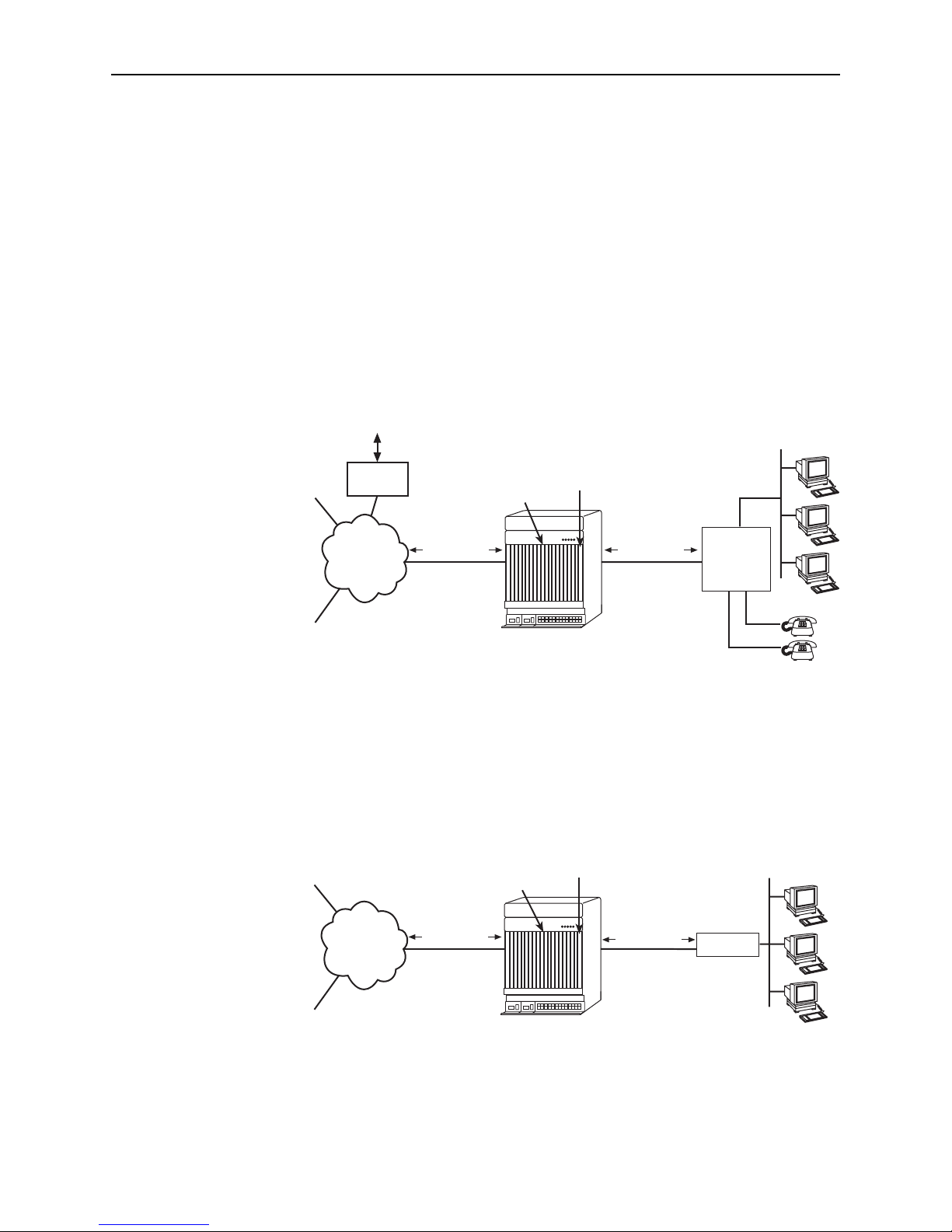
Sample Network Configurations
Figure 1-1 shows the ATM Line Card used to carry voice over DSL.
Figure 1-1. Endpoint with Voice Interfaces
Figure 1-2 shows a configuration in which the endpoints include a router to provide
data encapsulation.
Figure 1-2. Router Endpoint
05-17444-02
AT M
Network
ATM Cells
DSL
Integrated
Access
Device
(IAD)
SCP Card
ATM
Line Card
8820 BLC
Customer Premises
LAN
ISP
Corporate
Site
ATM Cells
Voice
Gateway
PSTN Voice
Traffic
05-17443-03
AT M
Network
Router
ATM Cells
ATM Cells
DSL
SCP Card
ATM
Line Card
8820 BLC
Customer Premises
LAN
ISP
Corporate
Site

1. About the ATM Line Cards
1-4 August 2005 8900-A2-GB20-50
SNMP Management Capabilities
The ATM Line Cards support SNMP Version 1, and can be managed by
Paradyne’s GrandVIEW
®
or any industry-standard SNMP manager.
Management Information Base (MIB) Support
For a detailed description of supported MIBs, visit Paradyne’s Web site at
www.paradyne.com. The following MIBs are supported:
ATM Forum SNMP M4 Network Element View (af-nm-0095.001)
Definitions of Managed Objects for the ADSL Lines (RFC 2662)
Definitions of Managed Objects for ATM Management (RFC 2515)
Definitions of Managed Objects for HDSL2 and SHDSL Lines
(draft-ietf-adslmib-hdsl2-10.txt)
Definitions of Textual Conventions and OBJECT-IDENTITIES for ATM
Management (RFC 2514)
Evolution of MIB II Interfaces (RFC 2863)
ADSL Extension MIB (Models 8965, 8975, and 8968)
(draft-ietf-adslmib-adslext.txt)
SHDSL MIB (Model 8985 only) (draft-ietf-adslmib-hdsl2.txt)
Entity MIB Using SMIv2 (RFC 2037)
MIB II and the Interfaces Group MIB (RFC 1213, RFC 2233)
Paradyne enterprise MIBs for:
— xDSL Interface
— SLE Device Control
— SLE Device Health and Status
—MaxVciVpi-MIB Table
—IF-MIB Table
— ATM VPL Statistics Table
SNMP Trap Support
The ATM Line Cards support SNMP traps as shown in the 8620 and 8820
Broadband Loop Carrier SNMP Reference.

8900-A2-GB20-50 August 2005 2-1
2
Accessing the SCP Card Web Interface
Introduction
The ATM line cards can be configured and monitored using:
The SCP card’s Command Line Interface (see the 8620 and 8820 Broadband
Loop Carrier Command Line Interface Reference) or TL1 interface (see the
8620 and 8820 Broadband Loop Carrier TL1 Interface Reference)
GrandVIEW EMS 4.1 or above (see the GrandVIEW EMS User’s Guide)
SNMP using another EMS (see the 8620 and 8820 Broadband Loop Carrier
SNMP Reference)
The web interface of the Shelf Concentration and Processing (SCP) card.
Logging Into the Web Interface
To access the web interface:
Procedure
1. Open your web browser. (Internet Explorer Version 6 or above is
recommended.)
2. Type http:// and the IP address of the SCP card into the Address field of your
browser window. For example:
The default address is 10.10.10.10.
3. A login window appears. Enter the User ID and Password, and click on OK.
The web interface screen appears. The web interface screens consist of a
header, a menu frame, and a content frame.
2. Accessing the SCP Card Web Interface
2-2 August 2005 8900-A2-GB20-50
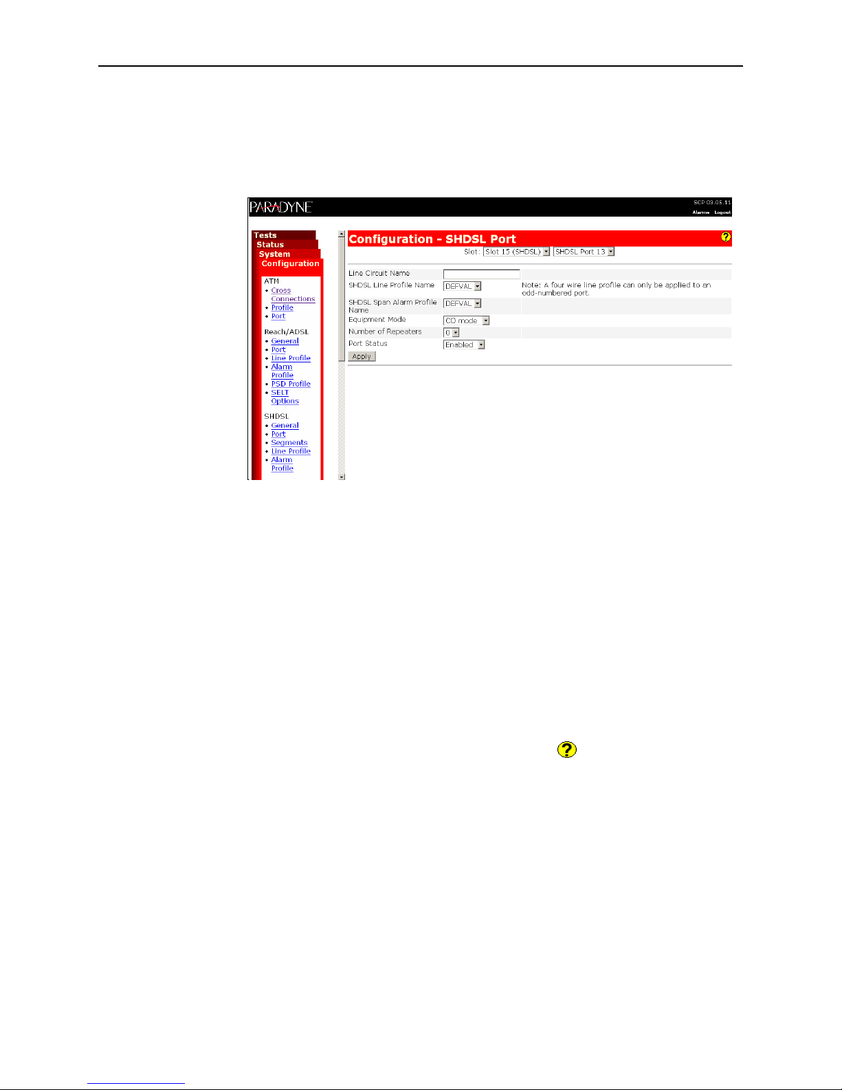
4. Click on the Configuration menu tab. The configuration screens available in
the contents frame depend on the types of line cards and type of SCP card
installed in the chassis. The Configuration - SHDSL Port screen is displayed
here.
All main screens of the web interface can be reached by clicking on hyperlinks in
the four menus:
Configuration – Configure the system and interfaces
Status – Display statistics, status, performance information, and contents of
memory
System – Display system information, download firmware, back up
configurations, and reset the SCP card
Tests – Start and stop tests
Help Button
For more information about any screen, click on the Help button on the screen.
Help is displayed in a new window.
Ending a Session
To end a session, close your web browser. This prevents an unauthorized user
from accessing the system using your user name and password.

8900-A2-GB20-50 August 2005 3-1
3
Configuration Using the Web Interface
Overview
This chapter provides instructions on how to configure the ATM line cards using
the SCP card’s web interface.
Configuring Spectrum Management
Use the Configuration - DSL General screen to enable and disable Spectrum
Management. When Spectrum Management is enabled, the maximum transmit
speeds and maximum transmit power are limited to meet local spectrum
management guidelines.
Procedure
To enable or disable Spectrum Management:
1. Select Disable or Enable from the drop-down list.
2. For the 8985 line card, additionally select the Spectrum Management Region:
— ANSI T1417 – To select American National Standards Institute T1.417
definitions
— ANFP ND 1602 – To select Access Network Frequency Plan ND1602
definitions
3. Click on Apply.
If you would like to configure the
card using . . . See the . . .
The BLC’s TL1 Interface (when an SCP
card with an ATM uplink is used)
8620 and 8820 Broadband Loop Carrier TL1
Interface Reference
The BLC’s router-like command line
interface (when an SCP card with an IP
uplink is used)
8620 and 8820 Broadband Loop Carrier
Command Line Interface Reference
GrandVIEW EMS GrandVIEW EMS User’s Guide
SNMP using another EMS 8620 and 8820 Broadband Loop Carrier SNMP
Reference

3. Configuration Using the Web Interface
3-2 August 2005 8900-A2-GB20-50
Configuring ReachDSL Ports (8955 and 8975)
Use the Configuration - DSL Port screen to set parameters for a DSL port on the
Model 8955 ReachDSL or Model 8975 ReachDSL+ line card.
Procedure
To configure a ReachDSL port:
1. Select a Port from the drop-down list and click on Select. Current values for
the port are displayed.
2. Enter or select the following fields:
Field Description
Line Circuit Name Enter a name from 1 to 255 characters long to indicate to
whom the port is assigned. The following values are
reserved and cannot be used: AVAILABLE (port is not
assigned), and FAULTY (port is faulty and can not be
assigned).
Line Type For the Model 8975 ReachDSL+ card, specify the line
type:
ADSL – The port supports only ADSL
ReachDSL – The port supports only ReachDSL
Dual Mode – The port supports both ADSL and
ReachDSL
This option does not appear for the Model 8955 line card.
Line Code For the Model 8975 ReachDSL+ card, select the ADSL
type supported:
MultiMode - The port uses the line code of its partner
modem
ANSI T1.413 - The port uses DMT modulation
ITU G.dmt Annex A - The port uses G.992.1 Annex A
modulation
ITU G.dmt Annex B - The port uses G.992.1 Annex B
modulation
ITU G.lite - The port uses G.992.2 modulation
The Line Code parameter has no effect on a Model 8955
ReachDSL card.
DSL Line Profile Name Enter the name of a DSL line profile to set rates for the
port.
DSL Alarm Profile Name Enter the name of a DSL alarm profile to set alarm
thresholds for the port.

3. Configuration Using the Web Interface
8900-A2-GB20-50 August 2005
3-3
3. Click on Apply.
Configuring ADSL Ports (8965, 8968)
Use the Configuration - DSL Port screen to set parameters for an ADSL port on
the 8965 or 8968 line card.
Procedure
To configure an ADSL port:
1. Select a Port from the drop-down list and click on Select. Current values for
the port are displayed.
2. Enter or select the following fields:
Max Tx Power Specify the maximum transmit power setting for the
ATU-C. The allowable Maximum Transmit Power range
may be limited according to local spectrum management
guidlines. The actual transmit power level will be based
upon the symbol rate selected to maximize the transmit
data rate and may be lower than the Maximum Transmit
Power level configured.
Far End Max Tx Power Specify the maximum transmit power setting for the
ATU-R. The allowable Maximum Transmit Power range
may be limited according to local spectrum management
guidlines. The actual transmit power level will be based
upon the symbol rate selected to maximize the transmit
data rate and may be lower than the Maximum Transmit
Power level configured.
Port Status Select Enabled, Disabled, or Reset from the drop-down
list to determine the status of the port.
Field Description
Field Description
Line Circuit Name Enter a name from 1 to 255 characters long to indicate to
whom the port is assigned. The following values are
reserved and cannot be used: AVAILABLE (port is not
assigned), and FAULTY (port is faulty and can not be
assigned).
 Loading...