

Paradyne 8922 Installation And User Manual

8922 POTS Card
Installation and User’s Guide
Document Number 8922-A2-GN10-10
November 2004
Contents
Software and Firmware License Agreement ................................................. 2
Product Documentation Online ..................................................................... 4
8922 POTS Card Description ....................................................................... 5
Installation Overview ..................................................................................... 6
Installing POTS Cards .................................................................................. 6
Front Panel LEDs ......................................................................................... 8
Cabling .......................................................................................................... 9
Web Interface ................................................................................................ 12
Web Interface – Configuration ...................................................................... 12
Web Interface – Status ................................................................................. 13
Web Interface – Tests ................................................................................... 14
TL1 Interface ................................................................................................. 15
Command Line Interface .............................................................................. 15
Test Access Path (TAP) Architecture ........................................................... 15
TL1 Interface and CLI Test Commands ........................................................ 18
RJ21X (CA21A) Connector Pin Assignments ............................................... 19
Technical Specifications ................................................................................ 20
Warranty, Sales, Service, and Training Information ...................................... 21
Document Feedback ..................................................................................... 21
Trademarks ................................................................................................... 21
1

Software and Firmware License Agreement
ONCE YOU HAVE READ THIS LICENSE AGREEMENT AND AGREE TO ITS
TERMS, YOU MAY USE THE SOFTWARE AND/OR FIRMWARE INCORPORATED
INTO THE PARADYNE PRODUCT. BY USING THE PARADYNE PRODUCT YOU
SHOW YOUR ACCEPTANCE OF THE TERMS OF THIS LICENSE AGREEMENT.
IN THE EVENT THAT YOU DO NOT AGREE WITH ANY OF THE TERMS OF THIS
LICENSE AGREEMENT, PROMPTLY RETURN THE UNUSED PRODUCT IN ITS
ORIGINAL PACKAGING AND YOUR SALES RECEIPT OR INVOICE TO THE
LOCATION WHERE YOU OBTAINED THE PARADYNE PRODUCT OR THE
LOCATION FROM WHICH IT WAS SHIPPED TO YOU, AS APPLICABLE, AND YOU
WILL RECEIVE A REFUND OR CREDIT FOR THE PARADYNE PRODUCT
PURCHASED BY YOU.
The terms and conditions of this License Agreement (the “Agreement”) will apply to the
software and/or firmware (individually or collectively the “Software”) incorporated into
the Paradyne product (the “Product”) purchased by you and any derivatives obtained
from the Software, including any copy of either. If you have executed a separate written
agreement covering the Software supplied to you under this purchase, such separate
written agreement shall govern.
Paradyne Corporation (“Paradyne”) grants to you, and you (“Licensee”) agree to accept
a personal, non-transferable, non-exclusive, right (without the right to sublicense) to use
the Software, solely as it is intended and solely as incorporated in the Product
purchased from Paradyne or its authorized distributor or reseller under the following
terms and conditions:
1. Ownership: The Software is the sole property of Paradyne and/or its licensors. The
Licensee acquires no title, right or interest in the Software other than the license
granted under this Agreement.
2. Licensee shall not use the Software in any country other than the country in which
the Product was rightfully purchased except upon prior written notice to Paradyne
and an agreement in writing to additional terms.
3. The Licensee shall not reverse engineer, decompile or disassemble the Software in
whole or in part.
4. The Licensee shall not copy the Software except for a single archival copy.
2

5. Except for the Product warranty contained in the manual, the Software is provided
“AS IS” and in its present state and condition and Paradyne makes no other
warranty whatsoever with respect to the Product purchased by you. THIS
AGREEMENT EXPRESSLY EXCLUDES ALL OTHER WARRANTIES, WHETHER
EXPRESS OR IMPLIED, OR ORAL OR WRITTEN, INCLUDING WITHOUT
LIMITATION:
a. Any warranty that the Software is error-free, will operate uninterrupted in your
operating environment, or is compatible with any equipment or software
configurations; and
b. ANY AND ALL IMPLIED WARRANTIES, INCLUDING WITHOUT LIMITATION
IMPLIED WARRANTIES OF MERCHANTABILITY, FITNESS FOR A
PARTICULAR PURPOSE AND NON-INFRINGEMENT.
Some states or other jurisdictions do not allow the exclusion of implied warranties
on limitations on how long an implied warranty lasts, so the above limitations may
not apply to you. This warranty gives you specific legal rights, and you may also
have other rights which vary from one state or jurisdiction to another.
6. IN NO EVENT WILL PARADYNE BE LIABLE TO LICENSEE FOR ANY
CONSEQUENTIAL, INCIDENTAL, PUNITIVE OR SPECIAL DAMAGES,
INCLUDING ANY LOST PROFITS OR LOST SAVINGS, LOSS OF BUSINESS
INFORMATION OR BUSINESS INTERRUPTION OR OTHER PECUNIARY LOSS
ARISING OUT OF THE USE OR INABILITY TO USE THE SOFTWARE,
WHETHER BASED ON CONTRACT, TORT, WARRANTY OR OTHER LEGAL OR
EQUITABLE GROUNDS, EVEN IF PARADYNE HAS BEEN ADVISED OF THE
POSSIBILITY OF SUCH DAMAGES, OR FOR ANY CLAIM BY ANY THIRD
PARTY.
7. The rights granted under this Agreement may not be assigned, sublicensed or
otherwise transferred by the Licensee to any third party without the prior written
consent of Paradyne.
8. This Agreement and the license granted under this Agreement shall be terminated
in the event of breach by the Licensee of any provisions of this Agreement.
9. Upon such termination, the Licensee shall refrain from any further use of the
Software and destroy the original and all copies of the Software in the possession of
Licensee together with all documentation and related materials.
10. This Agreement shall be governed by the laws of the State of Florida, without
regard to its provisions concerning conflicts of laws.
3

Product Documentation Online
Complete documentation for this product is available at www.paradyne.com.
Select Library → Technical Manuals.
Document Number Document Title
8400-A2-GB20 Shelf Concentration and Processing (SCP) Card User’s Guide
8400-A2-GZ40 Shelf Concentration and Processing (SCP) Card Installation
Instructions
8400-A3-GB21 8620 and 8820 Broadband Access Concentrators TL1
Reference
8400-A3-GB22 8620 and 8820 Broadband Access Concentrators Command
Line Interface (CLI) Reference
8620-A2-GN20 8620 Broadband Access Concentrator Installation Guide
8820-A2-GN20 8820 Broadband Access Concentrator Installation Guide
To order a paper copy of a Paradyne document, or to speak with a sales representative,
please call 1-727-530-2000.
4
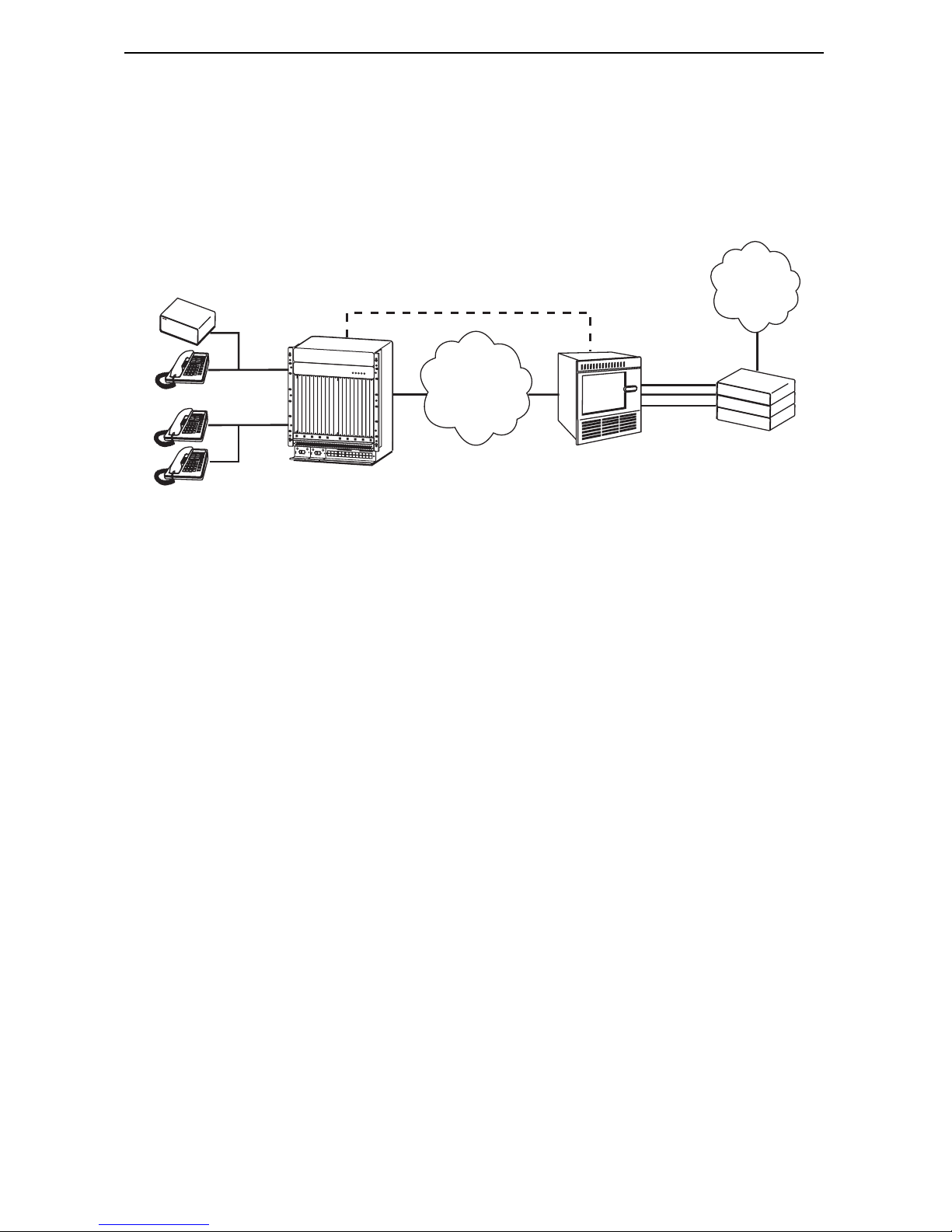
8922 POTS Card Description
The 8922 POTS (Plain Old Telephone Service) card can be used in any 8620 or 8820
Broadband Access Concentrator (BAC) managed by a Shelf Concentration and
Processing (SCP) card. The model 8820-A2-520 BAC is required for test access.
DSL + POTS
LES or MGCP Signaling
PSTN
GR-303,
P
O
W
E
R
A
L
A
R
M
S
A
B
F
a
n
M
a
j
o
r
M
i
n
o
r
V5.x
ATM
P
O
W
E
R
E
N
T
R
Y
M
O
D
U
L
E
L
E
F
T
C
U
L
N
I
O
T
:
C
L
I
N
K
E
A
P
S
O
W
E
E
R
R
E
I
A
N
T
L
R
Y
M
O
A
D
U
C
L
E
R
I
G
H
T
U
N
I
T
:
L
I
N
E
B
A
L
E
F
T
U
M
N
I
C
T
:
48V RTN
L
C
I
N
E
A
A
L
A
R
M
L
A
N
2
/
W
R
I
G
A
H
T
N
U
N
I
S
T
:
4
L
L
I
N
O
E
T
B
48V NEG
6
48V RTN
8
A
1
0
1
2
48V NEG
1
4
1
6
1
W
A
R
N
I
N
G
!
P
O
W
E
R
M
U
S
T
B
E
D
I
S
C
O
N
N
E
C
T
E
D
A
T
T
H
B
E
E
F
S
O
O
R
U
E
R
C
R
E
E
M
O
V
I
N
G
O
R
I
N
S
W
T
A
A
R
L
L
N
I
N
I
N
G
G
T
!
H
P
I
S
O
W
P
W
E
R
R
M
E
N
U
T
S
R
T
Y
B
M
E
O
D
D
I
S
U
C
L
O
E
N
N
E
C
T
E
D
A
T
T
H
B
E
E
F
S
O
O
R
U
E
R
R
E
M
O
V
I
N
G
O
R
I
N
S
T
A
L
L
I
N
G
T
H
I
S
P
W
R
E
N
T
R
Y
M
O
D
U
8
C
E
L
E
B
S
E
R
I
A
L
A
L
A
R
M
1
C
3
L
O
C
K
S
M
5
C
M
7
9
B
1
1
1
3
1
5
1
7
CPX-1000 MG
Class 5
Switch
8820 BAC
POTS Phones
with POTS Card
04-17538
Physical Description
Each 8922 POTS card connects through one 50-position Telco connector (RJ21X) on
the rear of the chassis. The card supports:
24 POTS ports
Standard 2-wire single party service
Loop start
DTMF and Pulse
5 REN
G.711 PCM, G.726 ADPCM, G.729 CELP
Test access for connection to an external test head (with Test Access System
Interface Module)
Custom Local Area Signaling Services
For a complete list of supported features, see Technical Specifications on page 20.
5

Installation Overview
In the course of installing the 8922 POTS card, you will:
❑ Obtain the applicable cable; refer to Cabling on page 9.
❑ Make sure the BAC is installed and power is supplied to the chassis.
❑ Install the card in the BAC.
❑ Connect to a 66 Block or other termination point.
❑ Configure your POTS card and IADs using the web or TL1 interface. Refer to the
SCP card’s online Help or the 8620 and 8820 Broadband Access Concentrators
TL1 Reference for configuration information.
Be sure to register your warranty at www.paradyne.com/warranty.
Installing POTS Cards
HANDLING PRECAUTIONS FOR
!
STATIC-SENSITIVE DEVICES
This product is designed to protect sensitive
components from damage due to electrostatic
discharge (ESD) during normal operation. When
performing installation procedures, however, take
proper static control precautions to prevent damage.
If you are not sure of the proper static control
precautions, contact your service representative.
A POTS card can be installed in, removed from, and replaced in a BAC without
disrupting service to the other cards in the chassis.
Procedure
To install the POTS card:
1. Determine in which slot the unit will be installed. Verify that cards in adjacent slots
have been fastened.
2. Remove the filler plate from the installation slot and store for possible later use.
6

3. Holding the POTS card vertically with component side facing right, insert it into the
top and bottom card guides.
POWER
ALARMS
BA
F
a
n
M
a
j
o
r
M
in
o
r
S
Y
S
T
E
M
O
K
A
lm
T
e
s
t
E
T
H
E
R
N
E
T
T
X
R
X
C
o
l
l
D
S
L
P
O
R
T
1
2
3
4
S
Y
S
T
E
M
O
K
A
lm
T
e
s
t
E
T
H
E
R
N
E
T
T
X
R
X
C
o
ll
DSL
P
O
W
E
R
E
N
T
R
Y
M
O
D
U
L
E
L
E
F
T
U
N
I
T
:
L
I
N
E
A
R
I
G
H
T
U
N
I
T
:
L
I
N
E
B
48V RTN
W
A
R
N
IN
G
!
POWER MUST BE DISCONNECTED AT THE SOURCE
BEFORE REMOVING OR INSTALLING THIS PWR ENTRY MODULE
48V NEG
W
BEFORE REMOVING OR INSTALLING THIS PWR ENTRY MODULE
P
O
W
E
R
E
N
T
R
Y
L
E
F
T
U
N
I
T
:
L
R
I
G
H
T
U
N
I
T
:
48V RTN
A
R
N
IN
G
!
POWER MUST BE DISCONNECTED AT THE SOURCE
MCP
CLO
C
K
SER
IA
L
M
O
D
I
N
E
A
L
I
N
E
A
U
L
E
B
C
A
M
C
C
ALAR
M
48V NEG
B
S
ERIAL
A
LA
RM
CLO
C
K
SM
C
M
2
1
4
35
LA
N/W
AN
SL
OT
6
8
A
10
12
14
16
18
7
9
B
11
13 15
17
00-16709
CAUTION:
Do not force the unit into the slot. This could damage the backplane
connectors. If the card does not seat properly, remove the card and reinstall
it. If it still does not seat properly, call your service representative.
4. Slide the unit into the slot until the power and network connectors seat firmly in the
mating connectors on the backplane.
The unit performs a power-on self-test. All of the LEDs turn ON and OFF briefly.
When the self-test is completed successfully, the SYSTEM OK LED begins to
pulse.
If the LED is not pulsing, notify your service representative. See Front Panel LEDs
on page 8.
5. Secure the unit by fastening the screws at each end of the faceplate.
7

Front Panel LEDs
The following table describes the meaning and states of the LEDs on the
front panel.
SYSTEM
Type LED LED is . . . *
SYSTEM OK Green, On
Off
Green, Pulsing
Alrm Amber, On
Off
Te s t Am be r, O n
Off
SYS BUS TX Off
Green, Fast
Blinking
RX Off
Indicating . . .
Card failure. System processing
functions have stopped.
No power to card.
Card is functioning normally.
Alarm is present on the card.
Normal operation, no alarms.
Test in progress.
Normal operation, no tests.
Inactive.
Cells are being transmitted.
Inactive, link down.
O
K
Alrm
T
est
SYS BUS
TX
R
X
LO
C
VOICE PORT
Green, Fast
Cells are being received.
Blinking
LOC Yellow, On
Loss Of Clock. ATM bus clock
signal is not present.
VOICE
PORT
VOICE
PORT
Off
Green, On
Green, Blinking
Normal operation.
At least one port is enabled and no
ports are in the off-hook state.
At least one port is enabled and in
the off-hook state.
Off
No ports are enabled.
* Pulsing: LED turns off momentarily once per second.
Fast Blinking: LED turns off and on in equal duration 4 times per
second.
POTS
8922
04-17537
8
 Loading...