

Page 1

Hotwire® TDM SDSL
Termination Units
Models 8777 and 8779
User’s Guide
Document No. 8700-A2-GB20-40
May 2002
Page 2

Copyright © 2002 Paradyne Corporation.
Al l rig h t s res erve d.
Printed in U.S.A.
Notice
This publi cation is protected by f ederal copyright law. No part of this publi cation may be copied or distrib uted,
transmitt ed, tr anscri bed, stor ed in a retrie v al syst em, or tr anslat ed into an y human or comput er langu age in any form or
by any mea ns, electronic, mechanical, magnetic, manual or otherwise, or disclosed to third parties wi thout the express
written permission of Paradyne Corporation, 8545 126th Ave. N., Larg o, FL 33773.
Par adyne Corporation makes no represe ntation or warranties wi th respect to the contents hereof and specifically
disclaims any implied warrantie s of merchantability or fitness for a particular purpose. Further, Paradyne Corporati on
reserves the right to revise this publication and to make changes from tim e to ti m e in the contents hereof without
obligation of Paradyne Corporation to notify any person of such revision or changes.
Changes and enhancements to the product and to the informat ion herein will be documented and issued as a new
release to this manual.
W arranty, Sales, Service, and Training Information
Contact yo ur loc al sales r eprese ntati v e, service r epresent ativ e , or dist ribut or di rec tly f or an y hel p need ed. F or addit ional
informati on concerning warranty, sales, service, repair, installation, documentation, training, distributor loca ti ons, or
Paradyne worldwide office locations, use one of the following methods:
Internet: Visit the Paradyne World Wide Web site at www.paradyne.com. (Be sure to regi ster your warrant y at
www.paradyne.com/warranty.
Telephone: Call our automated system to receive current information by fax or to speak with a company
representative.
— Within the U.S.A., call 1-800-870-2221
— Outside the U.S.A., call 1-727- 530-2340
Document Feedback
We welcome your comments and suggestions about this document. Please mail them to Technical Publications,
Par adyne Corporation, 8545 126th Ave. N., Largo, FL 33773, or send e-mail to [email protected]. Include the
number and title of this document in your correspondence. Please incl ude your name and phone number if you are
willing to pro vide additional clarificat ion.
Trademarks
ACCULINK, COMSPHERE, F rameSaver, Hotwire, MVL, NextEDGE, OpenL ane, and Performance Wizard are
registere d tr adem arks of Paradyne Corporation. ReachDSL and TruePut are trademarks of Paradyne Corporation. All
other product s and services mentioned herei n are the trademarks, service marks, registered trademarks, or registered
service marks of their respective owners.
Regulatory and Safety Information
Refer to th e appropriate Digital Subscriber Line Access Multiplexer (DSLAM) manual for all regul atory notices and
safety i nformation.
A
May 2002 8700-A2-GB20-40
Page 3

Contents
About This Guide
Document Purpose and Intended Audience . . . . . . . . . . . . . . . . . . . . v
New Features for this Release. . . . . . . . . . . . . . . . . . . . . . . . . . . . . . . v
Document Summary . . . . . . . . . . . . . . . . . . . . . . . . . . . . . . . . . . . . . . v
Product-Related Documents . . . . . . . . . . . . . . . . . . . . . . . . . . . . . . . . vi
1 About Hotwire 8777 and 8779 TDM SDSL Units
TDM SDSL Overview. . . . . . . . . . . . . . . . . . . . . . . . . . . . . . . . . . . . . . 1-1
TDM SDSL Features . . . . . . . . . . . . . . . . . . . . . . . . . . . . . . . . . . . . . . 1-2
Network Configuration . . . . . . . . . . . . . . . . . . . . . . . . . . . . . . . . . . . . . 1-3
SNMP Management Capabilities . . . . . . . . . . . . . . . . . . . . . . . . . . . . . 1-4
Management Information Base (MIB) Support . . . . . . . . . . . . . . . 1-4
SNMP Trap Support . . . . . . . . . . . . . . . . . . . . . . . . . . . . . . . . . . . 1-4
2 Using th e A s yn chronous Termina l In terface
User Interface Access . . . . . . . . . . . . . . . . . . . . . . . . . . . . . . . . . . . . . 2-1
Management Serial Port Settings . . . . . . . . . . . . . . . . . . . . . . . . . . . . 2-1
Logging In to the Hotwire DSLAM . . . . . . . . . . . . . . . . . . . . . . . . . . . . 2-2
Initi a ting an ATI Sess ion . . . . . . . . . . . . . . . . . . . . . . . . . . . . . . . . . . . 2-2
Menu Hierarchy . . . . . . . . . . . . . . . . . . . . . . . . . . . . . . . . . . . . . . . . . . 2-4
Screen Work Areas . . . . . . . . . . . . . . . . . . . . . . . . . . . . . . . . . . . . . . . 2-5
Navigating the Screens . . . . . . . . . . . . . . . . . . . . . . . . . . . . . . . . . . . . 2-6
Keyboard Keys . . . . . . . . . . . . . . . . . . . . . . . . . . . . . . . . . . . . . . . 2-6
Function Keys . . . . . . . . . . . . . . . . . . . . . . . . . . . . . . . . . . . . . . . . 2-7
Switching Between Screen Work Areas . . . . . . . . . . . . . . . . . . . . 2-8
Ending an ATI Session. . . . . . . . . . . . . . . . . . . . . . . . . . . . . . . . . . . . . 2-9
Exiting From the DSLAM Session . . . . . . . . . . . . . . . . . . . . . . . . . . . . 2-9
3 Initial Startup and Configuration
Overview . . . . . . . . . . . . . . . . . . . . . . . . . . . . . . . . . . . . . . . . . . . . . . . 3-1
Entering Identity Information . . . . . . . . . . . . . . . . . . . . . . . . . . . . . . . . 3-2
Configuring the Unit . . . . . . . . . . . . . . . . . . . . . . . . . . . . . . . . . . . . . . . 3-3
Configuration Options . . . . . . . . . . . . . . . . . . . . . . . . . . . . . . . . . . 3-3
8700-A2-GB20-40 May 2002
i
Page 4

Contents
Accessing and Displaying Configuration Options . . . . . . . . . . . . . . . . 3-4
Current and Default Factory Configurations . . . . . . . . . . . . . . . . . 3-5
Configuration Loader. . . . . . . . . . . . . . . . . . . . . . . . . . . . . . . . . . . 3-7
Saving Configuration Options . . . . . . . . . . . . . . . . . . . . . . . . . . . . . . . 3-9
Restoring Access to the User Interface . . . . . . . . . . . . . . . . . . . . . . . . 3-10
Resetting the Device . . . . . . . . . . . . . . . . . . . . . . . . . . . . . . . . . . . . . . 3-10
Disabling AutoRate . . . . . . . . . . . . . . . . . . . . . . . . . . . . . . . . . . . . . . . 3-11
Resetting AutoRate . . . . . . . . . . . . . . . . . . . . . . . . . . . . . . . . . . . . . . . 3-11
Downloading Firmware . . . . . . . . . . . . . . . . . . . . . . . . . . . . . . . . . . . . 3-12
4 Cross-Connecting Ports
Overview . . . . . . . . . . . . . . . . . . . . . . . . . . . . . . . . . . . . . . . . . . . . . . . 4-1
Determining the Configuration . . . . . . . . . . . . . . . . . . . . . . . . . . . . . . . 4-2
Setti n g t h e Cross-Conne ct Mode s . . . . . . . . . . . . . . . . . . . . . . . . . . . . 4- 4
Assigning Time Slots . . . . . . . . . . . . . . . . . . . . . . . . . . . . . . . . . . . . . . 4-5
5 IP Addressing
Selecting an IP Addressing Scheme . . . . . . . . . . . . . . . . . . . . . . . . . . 5-1
Configurations Not Running IP Conservative Software. . . . . . . . . 5-1
All Configurations. . . . . . . . . . . . . . . . . . . . . . . . . . . . . . . . . . . . . . 5-2
IP Addressing Example . . . . . . . . . . . . . . . . . . . . . . . . . . . . . . . . . . . . 5-2
6Security
Overview . . . . . . . . . . . . . . . . . . . . . . . . . . . . . . . . . . . . . . . . . . . . . . . 6-1
ATI Access Levels . . . . . . . . . . . . . . . . . . . . . . . . . . . . . . . . . . . . . . . . 6-2
Creating a Login . . . . . . . . . . . . . . . . . . . . . . . . . . . . . . . . . . . . . . . . . . 6-3
Deleting a Login. . . . . . . . . . . . . . . . . . . . . . . . . . . . . . . . . . . . . . . . . . 6-4
Controlling SNMP Ac c es s . . . . . . . . . . . . . . . . . . . . . . . . . . . . . . . . . . 6-5
Assigning SNMP Community Names and Access Types . . . . . . . 6-5
Limiting SNMP Access through the IP Addresses of the
Managers. . . . . . . . . . . . . . . . . . . . . . . . . . . . . . . . . . . . . . . . . . . . 6-5
7 Monitoring and Troubleshooting
What to Monitor . . . . . . . . . . . . . . . . . . . . . . . . . . . . . . . . . . . . . . . . . . 7-1
Viewing System and Test Status . . . . . . . . . . . . . . . . . . . . . . . . . . . . . 7-2
Health and Status Messages. . . . . . . . . . . . . . . . . . . . . . . . . . . . . 7-3
Self-Test Results Messages . . . . . . . . . . . . . . . . . . . . . . . . . . . . . 7-7
Test Status Messages. . . . . . . . . . . . . . . . . . . . . . . . . . . . . . . . . . 7-9
Device Messages. . . . . . . . . . . . . . . . . . . . . . . . . . . . . . . . . . . . . . . . . 7-10
ii
May 2002 8700-A2-GB20-40
Page 5

8Testing
Performance Statistics. . . . . . . . . . . . . . . . . . . . . . . . . . . . . . . . . . . . . 7-11
Viewing Network Error Statistics . . . . . . . . . . . . . . . . . . . . . . . . . . 7-12
Viewing Network Performance Statistics. . . . . . . . . . . . . . . . . . . . 7-13
Viewing DSX-1 Performance Statistics . . . . . . . . . . . . . . . . . . . . . 7-15
Viewing G.703 Performance Statistics . . . . . . . . . . . . . . . . . . . . . 7-17
Viewing Current Network Performance Statistics . . . . . . . . . . . . . 7-19
Viewing Inband Management Statistics . . . . . . . . . . . . . . . . . . . . 7-20
Viewing LED Status . . . . . . . . . . . . . . . . . . . . . . . . . . . . . . . . . . . . . . . 7-22
Front Panel LEDs. . . . . . . . . . . . . . . . . . . . . . . . . . . . . . . . . . . . . . . . . 7-24
Changing the Meaning of the PORTS LEDs . . . . . . . . . . . . . . . . . . . . 7-25
Troubleshooting . . . . . . . . . . . . . . . . . . . . . . . . . . . . . . . . . . . . . . . . . . 7-25
Accessing the Test Menu. . . . . . . . . . . . . . . . . . . . . . . . . . . . . . . . . . . 8-1
Running Network Tests . . . . . . . . . . . . . . . . . . . . . . . . . . . . . . . . . . . . 8-2
Network Line Loopback . . . . . . . . . . . . . . . . . . . . . . . . . . . . . . . . . 8-4
Repeater Loopback . . . . . . . . . . . . . . . . . . . . . . . . . . . . . . . . . . . . 8-5
DTE Loopback. . . . . . . . . . . . . . . . . . . . . . . . . . . . . . . . . . . . . . . . 8-6
Remote Send Line Loopback . . . . . . . . . . . . . . . . . . . . . . . . . . . . 8-7
Send and Monitor 511 . . . . . . . . . . . . . . . . . . . . . . . . . . . . . . . . . . 8-8
Device Tests . . . . . . . . . . . . . . . . . . . . . . . . . . . . . . . . . . . . . . . . . . . . 8-9
Lamp Test . . . . . . . . . . . . . . . . . . . . . . . . . . . . . . . . . . . . . . . . . . . 8-9
Ending an Active Test . . . . . . . . . . . . . . . . . . . . . . . . . . . . . . . . . . . . . 8-10
Telco-Initiated Tests. . . . . . . . . . . . . . . . . . . . . . . . . . . . . . . . . . . . . . . 8-11
Telco-Initiated Line Loopback . . . . . . . . . . . . . . . . . . . . . . . . . . . . 8-11
Telco-Initiated Payload Loopback . . . . . . . . . . . . . . . . . . . . . . . . . 8-11
Telco-Initiated Remote Line Loopback . . . . . . . . . . . . . . . . . . . . . 8-12
Contents
9 Transferring Firmware and Configura tions Using TFTP
Downloading Firmware . . . . . . . . . . . . . . . . . . . . . . . . . . . . . . . . . . . . 9-1
Configuration Loader . . . . . . . . . . . . . . . . . . . . . . . . . . . . . . . . . . . . . . 9-4
A Confi gur ati on O p ti ons
Overview . . . . . . . . . . . . . . . . . . . . . . . . . . . . . . . . . . . . . . . . . . . . . . . A-1
Network Interface Options Menu . . . . . . . . . . . . . . . . . . . . . . . . . . . . . A-2
DSX-1 Interface Options (Model 8777) . . . . . . . . . . . . . . . . . . . . . . . . A-7
G.703 Interface Options (Model 8779). . . . . . . . . . . . . . . . . . . . . . . . . A-9
Copy Ports Options . . . . . . . . . . . . . . . . . . . . . . . . . . . . . . . . . . . . . . . A-12
System Options . . . . . . . . . . . . . . . . . . . . . . . . . . . . . . . . . . . . . . . . . . A-13
8700-A2-GB20-40 May 2002
iii
Page 6

Contents
System Clock . . . . . . . . . . . . . . . . . . . . . . . . . . . . . . . . . . . . . . . . . . . . A-15
Cross-Connect . . . . . . . . . . . . . . . . . . . . . . . . . . . . . . . . . . . . . . . . . . . A-19
Setting Cross-Connect Mode. . . . . . . . . . . . . . . . . . . . . . . . . . . . . A-20
Assigning Time Slots. . . . . . . . . . . . . . . . . . . . . . . . . . . . . . . . . . . A-24
Management and Communication Options Menu . . . . . . . . . . . . . . . . A-28
Telnet Session Options . . . . . . . . . . . . . . . . . . . . . . . . . . . . . . . . . A-28
Gene ral SNMP Mana g e ment Options . . . . . . . . . . . . . . . . . . . . . . A-30
SNMP NMS Security Options . . . . . . . . . . . . . . . . . . . . . . . . . . . . A-32
SNMP Traps Options. . . . . . . . . . . . . . . . . . . . . . . . . . . . . . . . . . . A-34
Inband Management Channel (Model 8779) . . . . . . . . . . . . . . . . . A-37
Configuring and Testing Inband Management. . . . . . . . . . . . . . . . A-39
B S tanda rds Com plianc e for SNMP Traps
SNMP Traps. . . . . . . . . . . . . . . . . . . . . . . . . . . . . . . . . . . . . . . . . . . . . B-1
ifIndex. . . . . . . . . . . . . . . . . . . . . . . . . . . . . . . . . . . . . . . . . . . . . . . . . . B-1
warmStart. . . . . . . . . . . . . . . . . . . . . . . . . . . . . . . . . . . . . . . . . . . . . . . B-2
authenticationFailure . . . . . . . . . . . . . . . . . . . . . . . . . . . . . . . . . . . . . . B-2
linkUp and linkDown. . . . . . . . . . . . . . . . . . . . . . . . . . . . . . . . . . . . . . . B-2
Enterprise-Specific Traps. . . . . . . . . . . . . . . . . . . . . . . . . . . . . . . . . . . B-4
C Connector Pin Assignments
Overview . . . . . . . . . . . . . . . . . . . . . . . . . . . . . . . . . . . . . . . . . . . . . . . C-1
Front Panel 50-pin DTE Connector Pinouts. . . . . . . . . . . . . . . . . . . . . C -1
8610/8620 and 8810/8820 DSLAM Telco 50-pin Connecto r Pinouts . C-3
D Technical Specification s
E Cross-Connection Worksheets
Using the Worksheets . . . . . . . . . . . . . . . . . . . . . . . . . . . . . . . . . . . . . E-1
Port Connection Diagram. . . . . . . . . . . . . . . . . . . . . . . . . . . . . . . . . . . E-2
DSX-1 Time Slot Assignments. . . . . . . . . . . . . . . . . . . . . . . . . . . . . . . E-3
G.703 Time Slot Assignments . . . . . . . . . . . . . . . . . . . . . . . . . . . . . . . E-11
Index
iv
May 2002 8700-A2-GB20-40
Page 7

About This Guide
Document Purpose and Intended Audience
This guide contains information needed to set up, configure, and operate Hotwire
8777 and 8779 Time Division Multiplexer Symmetric Digital Subscriber Line
(TDM SDSL) Termination Units, and is intended for installers and operators.
New Features for this Re lease
This version of the
User’s Guide
Termination Unit.
Document Summary
Section Description
Chapter 1,
and 8779 TDM SDSL Units
Chapter 2,
Asynchronous Terminal Interface
Chapter 3,
Configuration
Chapter 4,
Ports
Chapter 5,
Chapter 6,
Chapter 7,
Troubleshooting
Hotwire TDM SDSL Termination Units, Models 8777 and 8779,
adds the inband management feature for the Model 8779
About Hotwire 8777
Using the
Initial Startup and
Cross-Connecting
IP Addressing
Security
Monitoring and
Describes the Hotwire Ter m ination Unit’s features
and capabilities.
Provides instructions for accessing the user interface
and navigating the screens.
Provides procedures for setting up the use r in terface
and configuring the unit .
Provides inst ructions for cross-connecting the time
slots of the DSL and DTE ports.
Provides IP addres sing requirements and examples.
Presents procedur es for creating a login, setti ng the
effecti ve access lev els, and controlling SNMP
access.
Describes using the LEDs , st atus messages, and
network statisti cs to monitor the unit and diagnose
problems.
Chapter 8,
8700-A2-GB20-40 May 2002
Testing
Provides instruct ions for running network, DSX-1,
and G.703 tests.
v
Page 8

About This Guide
Section Description
Chapter 9,
and Configurations Using TFTP
Appendix A,
Options
Appendix B,
Compliance for SNMP Traps
Appendix C,
Assignments
Appendix D,
Specifications
Appendix E,
Worksheets
Index
Transferring Firmware
Configuration
Standards
Connector Pin
Technical
Cross-Connection
Shows how to upload and download firmware and
configuration files.
Contains all configuration options, default settings,
and possible set tings.
Contains SNMP trap compliance information.
Lists the pin assignments for the front panel DTE
connector.
Contains physical and regulatory specifi cations,
network and port interfa ces, power consumption
values, and accessory part numbers.
Contains worksheets to help plan and configure
cross-connection of DTE and DSL ports.
Lists key terms, acronyms, c oncepts, and sections in
alphabetical order.
A master glossary of terms and acronyms used in Paradyne documents is
available on the World Wide Web at
Technical Manuals
→
Techn ical Glossary.
www.paradyne.com
. Select
Library →
Product-Related Documents
Complete documentation for this product is available on the World Wide Web at
www.paradyne.com
Systems.
Document Number Document Title
7900-A2-GB21
8000-A2-GB22
8000-A2-GB29
8610-A2-GN20
8620-A2-GN20
8810-A2-GN20
8820-A2-GN20
To order a paper copy of a Paradyne document:
. Select
Library → Technical Manuals → Hotwire DSL
Hotwire TDM SDSL Standalone Termination Units, Models
7974-A2, 7975-A2, and 7976 -A2, User's Guide
Hotwire Management Communications Controller (MCC) Card,
IP Conservative, User's Guide
Hotwire Management Communications Controller (MCC) Card
User's Guide
Hotwire 8610 DSLAM Installation Guide
Hotwire 8620 GranDSLAM Installation Guide
Hotwire 8810 DSLAM Installation Guide
Hotwire 8820 GranDSLAM Installation Guide
Within the U.S.A., call 1-800-PARADYNE (1-800-727-2396)
Outside the U.S.A., call 1-727-530-8623
vi
May 2002 8700-A2-GB20-40
Page 9

About Hotwire 8777 and 8779 TDM SDSL Units
TDM SDSL Overview
Hotwire® Time Division Multiplexer Symmetric Digital Subscriber Line (TDM
SDSL) products maximize customer service areas by varying the DSL line rate.
This ensures symmetric DSL connectivity over a wide range of telephone line
distances and transmission line qualities. Hotwire 2-wire TDM SDSL products
transmit data over 14,000 feet (4.6 km) at rates up to 2.048 Mbps.
Hotwire products support autorate. Units first synchronize to the highest line rate
that the 2-wire loop supports, then automatically configures the unit to the highest
multiple of 64 Kbps supported by that line rate. Eight line rates are available. At all
rates, an 8 Kbps management channel is available , which enables functions such
as firmware downloads to remote units. Units can also be configured manually to
full or fractional T1 or E1 rates.
1
8700-A2-GB20-40 May 2002
1-1
Page 10
1. About Hotwire 8777 and 8779 TDM SDSL Units
TDM SDSL Features
The 2-wire Hotwire 8777 or 8779 TDM SDSL Termination Unit is a circuit board
that is mounted in a Hotwire 8610 or 8810 Digital Subscriber Line Access
Multiplexer (DSLAM), or an 8620 or 8820 GranDSLAM, and used to transport
signals at high speeds over a twisted-pair connection.
Model . . . Has eight . . . And eight . . .
8777 TDM SDSL ports DSX-1 ports
8779 TDM SDSL ports G.703 ports
Hotwire 8777 and 8779 TDM SDSL Termination Units have these standard
features:
Cross-Connection Capability.
Any DSL port and time slot can be connected
to any DTE port and time slot.
Embedded Operations Channel (EOC).
Provides remote management via
SNMP or Tel net session capability over the DSL network. The bandwidth of
the EOC is a 4 Kbps dedicated channel for the Model 8777 and 8 Kbps for the
Model 8779.
Asynchronous Terminal Interface (ATI).
Provides a menu-driven
VT100-compatible terminal interface for configuring and managing the unit
locally or r e motely by Telnet ses s ion .
Local Management.
Provides local management using the DSLAM
management card with a:
— Terminal or PC via the Management Serial port of the DSLAM
— Network Management System (NMS) via the Management MCC port of
the DSLAM through the port card’s 10BaseT port
Remote Management.
Provides remote management:
— Out-of-band, using an external modem through the Management Serial
port of the DSLAM
— Inband using one of the DS0 channels as the management channel to
transport SNMP traffic to the MCC card (Model 8779 only).
— Via Teln et over the EOC
Alarm Indicati o n.
Diagnostics.
Activates front panel LEDs.
Provides the capability to diagnose device and network
problems and perform tests, including digital loopbacks, pattern tests, and
self-test.
Device and Test Monitoring.
Provides the capability of tracking and
evaluating the unit’s operation, including health and status, and error-rate
monitoring.
1-2
May 2002 8700-A2-GB20-40
Page 11
Network Configuration
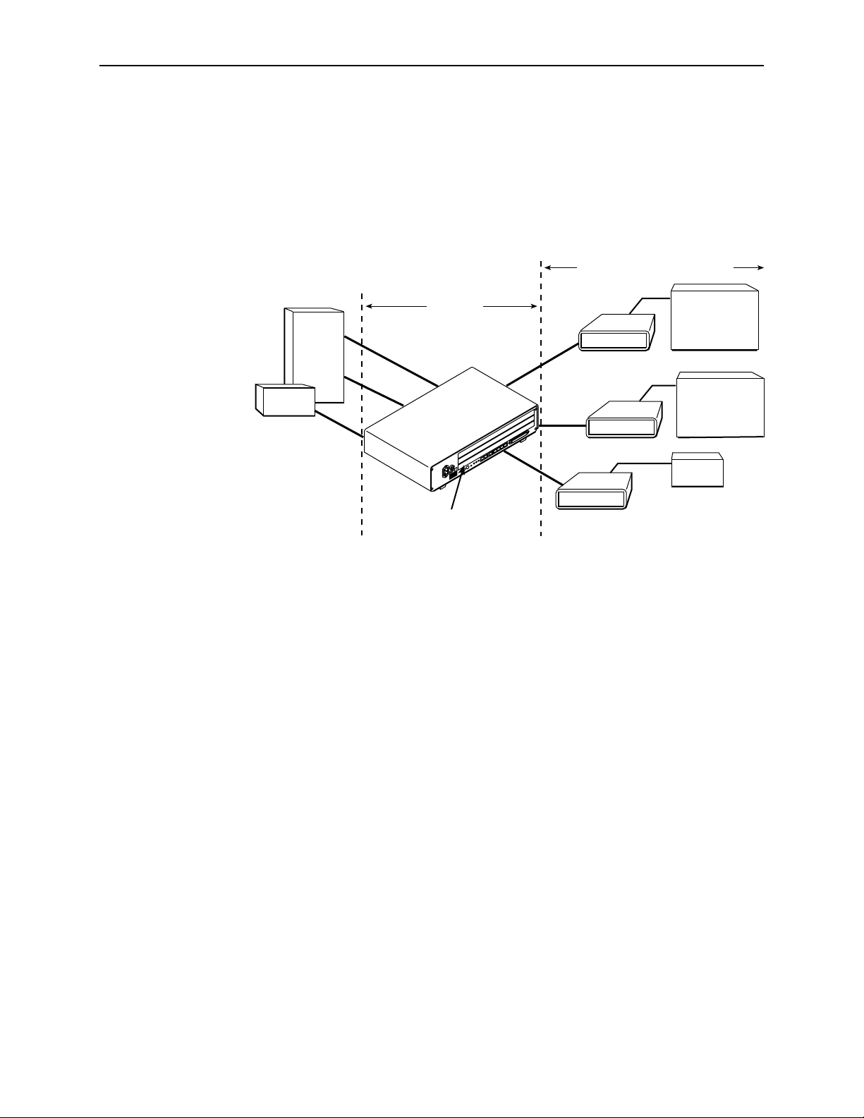
Figure 1-1, Sample CO-to-CP Configuration, shows a T1 network application
using a Hotwire 8777 or 8779 Termination Unit for access concentration in a
central office (CO). A frame relay switch and a router are connected to partne r
units through the termination unit, supporting a host or router and frame relay
encapsulated or unframed data.
Frame
Relay
Switch
Router
DSX-1
DSX-1
DSX-1
CO Site
1. About Hotwire 8777 and 8779 TDM SDSL Units
Customer Premises (CP)
1.544 Mb
DSX-1
7974
DSX-1
7974
EIA-530
7975
T1 Host
(Frame Relay
Encapsulated
Data)
Router
(Frame Relay
Encapsulated
Data)
Router
87xx T ermination Unit
in 8610 Series DSLAM
Figure 1-1. Sample CO-to-CP Configuration
00-16414-02
8700-A2-GB20-40 May 2002
1-3
Page 12

1. About Hotwire 8777 and 8779 TDM SDSL Units
SNMP Management Capabilities
The termination unit suppor t s SNM P Version 1, and can be managed by any
industry-standard SNMP manager and accessed using SNMP by external SNMP
managers.
Management Information Base (MIB) Support
For a detailed description of supported MIBs, visit Paradyne’s Web site at
www.paradyne.com
. The following MIBs are supported:
SNMP Trap Support
MIB II (RFC 1213 and RFC 2863 (was 1573))
for use with a network management protocol in TCP/IP internets and provides
general information about the unit. MIB II is backward-compatible with MIB I.
DS1/E1 MIB (RFC 2495 (was 1406))
DSX-1 or G.703 interface and supports the features found on the DSX-1 or
G.703 Perform anc e Statistics screen.
Entity MIB (RFC 2037)
Enterprise MIBs
The Hotwire 8777 or 8779 TDM SDSL Termination Unit suppor ts SNM P traps as
shown in Appendix B,
– Suppor ts all DSLAM cards.
– Supports configuration, status, statistics, and tests.
Standards Compliance for SNMP Traps
– Reports the performance status of the
– Defines the general objects
.
1-4
May 2002 8700-A2-GB20-40
Page 13

Using the Asynchronous Terminal Interface
User Interface Access
You can communicate with the asynchronous terminal interface (ATI) using one of
the following methods:
Direct connection through the Management Serial port of the DSLAM (locally
or via an external modem).
Tel net session using a Network Manag eme nt System (NMS) connected to a
LAN/WAN port on the DSLAM.
Tel net session through the Embedded Operation s Channel (EOC ).
2
NOTE:
Only one asynchronous terminal interface session can be active at a time, and
another user’s session cannot be forced to end. To automatically log out a
user due to inactivity, enable the Inactivity Timeout option (see Table A-12,
Telnet Session Options, in Appendix A,
Security can limit ATI access in several ways. To set up security or a login ID, refer
to Chapter 6,
Security
.
Management Serial Port Settings
Ensure that the device you connect communicates using these settings:
Data rate set to 9.6 Kbps.
Character length set to 8.
Parity set to None.
Stop Bits set to 1.
Refer to the installation document for your DSLAM. See
Documents
in
About This Guide
Configuration Options
Product-Related
.
).
8700-A2-GB20-40 May 2002
2-1
Page 14

2. Using the Asynchronous Terminal Interface
Logging In to the Hotwire DSLAM
You can log in to the Hotwire DSLAM system using either a local
VT100-compatible terminal or a remote T elnet connection.
After you enter yo u r us er ID and pass wo r d, the system displays the Hotwire
Chassis Main Menu. See your management card documentation for information
about selecting the unit from the card selection screen.
Initiating an ATI Session
The Main Menu screen is displayed unless a login ID and password is required or
the ATI is already in use.
If security is enabled on the termination unit and Telnet is used to access the unit
directly (you did not log in through the MCC), the system prompts you for a login
ID and password.
Login
Slot: 4
LOGIN
Login ID:
Enter Password:
-------------------------------------------------------------------------------Ctrl-a to access these functions E
Model: 87xx
xit
If you enter an invalid login ID and pass word three times, the Telnet session closes
or the terminal connection returns to an idle state. Refer to Chapter 6,
If the ATI is already in use, the message
connection refused
is sent to a
Security
.
terminal attempting Telnet access.
2-2
May 2002 8700-A2-GB20-40
Page 15

Screen
Area
Function Keys
and
Message Area
2. Using the Asynchronous Terminal Interface
After you enter a valid login ID and password, the Main Menu appears.
main Access Level: Administrator
Slot: 4 Model 87xx
MAIN MENU
Status
Test
Configuration
Control
-------------------------------------------------------------------------------Ctrl-a to access these functions Exit
Entry to all of the termination unit’s tasks begins at the Main Menu screen.
Selec t . . . To . . .
Status View system status, diagnostic test res ults, statistics, LED, and device
identity information.
Test Select, start , stop and cancel tests for the unit’s interf aces.
Configuration Display and edit the configurati on options and download configuration
files.
Control Change the device identity, administer logins, download new firmwar e, or
initiate a power -up reset of the unit.
What appears on the screens depends on the:
Current configuration
Effective security access level
– How your unit is currently configured.
– An access lev el that is typically set by the
system administrator for each interface and each user.
Data selection criteria
– What you entered in previous screens.
8700-A2-GB20-40 May 2002
2-3
Page 16
2. Using the Asynchronous Terminal Interface
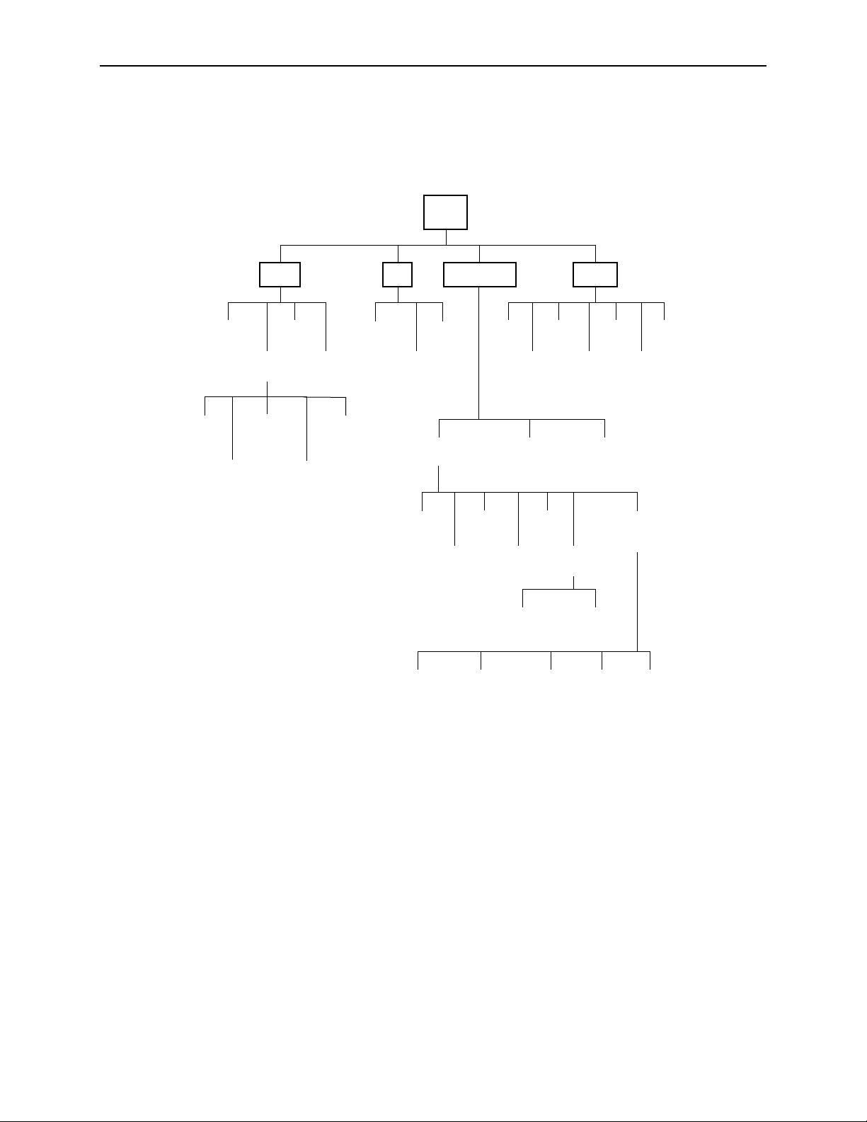
Menu Hierarchy
The following illustration shows the paths to the various ATI screens.
Main
System and
Test Status
Network
Error
Statistics
Network
Performance
Statistics
Status Test
Display
LEDs
Performance
Statistics
DSX-1/G.703
Statistics
Identity
Inband
Management
Statistics
Current
Network
Performance
Statistics
Network and
DSX-1/G.703
Tests
Device
Tests
Current Configuration
Network
Telnet
Session
Configuration Control
Abort All
Tests
Edit/Display
DSX-1/
G.703
General SNMP
Change
Identity
Administer
Configuration
Copy
Ports
System
Options
Set Cross
Connect Mode
Management
Logins
Loader
System
Clock
SNMP NMS
Security
Download
Code
Apply
Download
Default Factory
Configuration
Cross
Connect
Time Slots
Port
LEDs
Reset
AutoRate
Management
and
Communication
Assign
SNMP
Traps
Management
Reset
Device
Inband
Channel
02-16607-03
2-4
May 2002 8700-A2-GB20-40
Page 17

Screen Work Areas
There are two user work areas:
2. Using the Asynchronous Terminal Interface
Menu
Path
Input
Fields
Screen area
– This is the area above the dotted line that provides the menu
path, menus, and input fields.
The menu path appears as the first line on the screen. In this manual, the
menu path is presented as a menu selection sequence:
Main Menu→Configuration
Function keys and message area
→
Current Configuration→Network
– This is the area below the dotted line
that lists function keys specific to the screen, field value choices, and system
messages (displays the highest level alarm from the Heal th and Status
screen).
main/config/network
Slot: 4
Port: 3
NETWORK INTERFACE OPTIONS
Port Status Enable
Margin Threshold: –3db
Excessive Error Rate Threshold: 1E–5
AutoRate: Disable
DSL Line Rate: 1552 kbps
EIA-530 Payload Rate 1536
Transmit Attenuation 0dB
Peer IP Address: 111.255.255.000 Clear
Model: 87xx
kbps
Function
Keys
Field Value
Choices
Circuit Identifier: Clear
-------------------------------------------------------------------------------Ctrl-a to access these functions, ESC for previous menu M
ave
S
Select: 1E–4, 1E–5, 1E–6, 1E–7, 1E–8, 1E–9 LOS at Net, Pt 1
ainMenu Exit
System
Messages
8700-A2-GB20-40 May 2002
2-5
Page 18

2. Using the Asynchronous Terminal Interface
Navigating the Screens
You can navigate the screens by:
Using keyboard keys
Using function keys
Switching between the two screen areas
Keyboard Keys
Use the following keyboard keys to navigate within the screen.
Press . . . To . . .
Ctrl-a Move cursor between the screen area and the function keys and
Esc Return to the previous screen.
messages area below the dotted line at the bottom of the screen.
Tab Move cursor to the next field on the screen.
Backspace Move cursor to the previous field on the screen.
Enter Accept entry or display valid options on the last row of the screen
when pressed before entering data or after entering invalid data.
Ctrl-k Tab backwar ds (move cursor one field to the left).
Spacebar Select the next valid value for t he field.
Delete (Del) Delete ch aracter that the cursor is on.
Up Arrow or Ctrl-u Move cursor up one fi eld within a column on the same screen.
Down Arrow or Ctrl-d Move cursor down one field within a column on th e same screen.
Right Arrow or Ctrl-f Move cursor one charac ter to the right if in edit mode.
Left Arrow or Ctrl-b Move cursor one character to t he lef t if in edit mode.
Ctrl-l Redraw the screen display, clearing information typed in but not
yet entered.
Procedure
To m ake a menu or field selection:
1. Press the Tab or Down Arrow key to position the cursor on a menu or field
selection. Each selection is highlighted as you press the key to move the
cursor from position to position.
2. Press Enter. The selected menu or screen appears.
3. Continue Steps 1 and 2 until you reach the screen you want.
2-6
May 2002 8700-A2-GB20-40
Page 19

Function Keys
2. Using the Asynchronous Terminal Interface
The current setting or value appears to the right of the field name. You can enter
information into a selected field by:
Typing in the first letter(s) of a field value or command.
Switching from the screen area to the function key and message area below
the dotted line, and selecting or entering the designated function key.
If a field is blank and the Field Value Choices display valid selections, press the
spacebar; the first valid value for the field will appear in the field. Continue
pressing the spacebar to scroll through other valid values. Press Enter to select
the value.
All function keys located below the dotted line operate the same way (upper- or
lowercase) throughout the screens.
For the screen
funct i on . . . Sel ect . . . A n d pre ss Ent er to . . .
ClrFar F or f Clear far- end network statistics and refresh the screen.
ClrN
ear N or n Clear near-end netw ork statistics and refresh the screen.
Del
ete L or l Delete data.
xit E or e Terminate the asynchronous terminal session.
E
M
ainMenu M or m Return to the Main Menu screen.
N
ew N or n Enter new data.
PgD
n D or d Display the next page, or group of entries.
PgU
p U or u Display the previous page, or group of entries.
R
esetMon R or r Reset an active Monitor 511 test counter to zer o.
ave S or s Save information.
S
8700-A2-GB20-40 May 2002
2-7
Page 20

2. Using the Asynchronous Terminal Interface
Switching Between Screen Work Areas
Select Ctrl-a to switch between the two screen work areas to perform all screen
functions.
Procedure
To acc ess the function key and message area below the dotted line:
1. Press Ctrl-a to switch from the screen area to the function key and message
area below the dotted line.
2. Select either the function’s designated (underlined) character or press the Tab
key until you reach the desired function key.
Example:
To save the current options, type s or S (Save).
3. Press Enter. The function is performed.
4. To return to the screen area above the dotted line, press Ctrl-a again.
main/config/network
Slot: 4 Model: 87xx
Port: 2
NETWORK INTERFACE OPTIONS
Margin Threshold: –3db
Excessive Error Rate Threshold: 1E–5
AutoRate: Disable
DSL Line Rate: 1552
Circuit Identifier: Clear
-------------------------------------------------------------------------------Ctrl-a to access these functions, ESC for previous menu M
S
ave
ainMenu Exit
2-8
May 2002 8700-A2-GB20-40
Page 21

Ending an ATI Session
Use the Exit function key from any screen to terminate the session.
Procedure
To end a ses sion with the asynch ronous ter m inal interface:
1. Press Ctrl-a to go to the function keys below the dotted line.
2. Save changes if required. A confirmation message appears if you have made
but not saved changes to your configuration.
2. Using the Asynchronous Terminal Interface
3. Tab to E
through the management card, the Hotwire Chassis Card Selection menu
appears.
xit (or type e or E) and press Enter. If you have accessed the unit
Exiting From th e D SLAM Session
You can manually log out of the system or, after five minutes of inactivity, the
system will automatically log you out.
Procedure
To m anually exit from the Hotwire DSLAM system:
1. Return to the Hotwire Chassis Main Menu by selecting Exit from either the
Hotwire – MCC menu or the Hotwire – DSL menu.
The Hotwire Card Selection menu appears.
2. Press Ctrl-z.
The Hotwire Chassis Main Menu appears.
3. From the Hotwire Chassis Main Menu, select Logout.
The system exits from the current login session on the Hotwire DSLAM.
8700-A2-GB20-40 May 2002
2-9
Page 22

2. Using the Asynchronous Terminal Interface
2-10
May 2002 8700-A2-GB20-40
Page 23

Initial Start up and Configuration
Overview
This chapter provides instructions on how to access and configure your Hotwire
TDM SDSL Termination Unit for the first time, display configuration options,
disable or reset the AutoRate feature, and download firmware. These procedures
include:
3
Entering Identity Information
Configuring the Unit
Accessing and Displaying Configuration Options
—
Configuration Options
—
Current and Default Factory Configurations
—
Configuration Loader
Saving Configuration Options
Restoring Access to the User Inter face
Resetting the Devi ce
Disabling AutoRate
Resetting Au to Rate
Downloading Firmware
on page 3-3
on page 3-10
on page 3-11
on page 3-11
on page 3-2
on page 3-9
on page 3-12
on page 3-4
on page 3-10
8700-A2-GB20-40 May 2002
3-1
Page 24

3. Initial Start up and Configuration
Enteri n g Id en tity Information
After accessing your unit for the first time, use the Change Identity screen to
determine SNMP administrative system information that will be displayed on the
Identity screen of the Status branch. T o access the Card Identity screen, follow this
menu selection sequence:
Main Menu→Control→Change Identity
main/control/change_identity
Slot: 4 Model: 87xx
IDENTITY
System Name: Prez lllQJ98-001 Clear
System Location: Bldg. A412, 2nd Floor, Left cabinet
System Contact: L. Young 800-727-2396 pager 888-555-1212 Clear
Clear
-------------------------------------------------------------------------------Ctrl-a to access these functions, ESC for previous menu M
S
ave
ainMenu Exit
The three System entry fields are alphanumeric and provide up to 128 characters
per field. These SNMP System entry fields are:
System Name:
System Location:
System Contact:
The general SNMP system name.
The physical location of the SNMP-managed device.
Identification information, such as contact name, phone
number, or mailing address.
Val i d entry values are any printable ASCII character. ASCII printable characters
include:
Numeric 0–9
Upper- or lowercase A–Z
Space
All ASCII symbols except the caret (^)
Select Clear to reset a field to a null value.
3-2
May 2002 8700-A2-GB20-40
Page 25

3. Initial Startup and Configuration
Procedure
To ent er Change Id entity screen information:
1. Position the cursor in the System Name field. Enter a name unique in your
network to identify the SNMP managed node (or unit)
2. Position the cursor in the System Location field. Enter the physical location of
the unit.
3. Position the cursor in the System Contact field. Enter the name and contact
information for the person responsible for the unit.
4. Press Ctrl-a to switch to the function key and message area below the dotted
line.
5. Select S
Configuring the Unit
Configuration option settings determine how the termination unit operates. Use the
Configuration branch menu to display or change configuration option settings.
Configuration Options
The termination unit is shipped with factory settings in the Default Factory
Configuration area. You can find default information by:
Referring to Appendix A,
Accessing the Configuration branch of the termination unit’s menu.
The termination unit has two sets of configuration option settings.
Configuration Option Area Configuration Option Set
Current Configuration The unit’s currently acti ve set of configuration options.
Default Factory Configuration A read-only configuration area containing the factory
ave and press Enter.
Configuration Options
default configuration options.
Command Complete
.
appears.
The Current Configuration matches the Default Factory Configuration until
modified and saved by the user. If the factory default settings do not support your
network’s configuration, you can customize the configuration options for your
application.
8700-A2-GB20-40 May 2002
3-3
Page 26

3. Initial Start up and Configuration
Accessing and Displaying Configuration Options
To displ ay configuration options, you must first load a configuration into the edit
area.
To load a configuration option set into the configuration edit area, follow this menu
selection sequence:
Main Menu→Configuration (Load Configuration From)
main/configuration
Slot: 4 Model: 87xx
LOAD CONFIGURATION FROM:
Current Configuration
Configuration Loader
Default Factory Configuration
------------------------------------------------------------------------------Ctrl-a to access these functions, ESC for previous menu MainMenu Exit
Make a selection by placing the cursor at your choice and pressing Enter.
If you s elect . . . Then . . .
Current
Configuration
Configuration
Loader
Default Factory
Configuration
The selected configuration option set is load ed and the
Configuration Edit/Display menu screen appears.
The Configuration Loader screen is displayed allowing you to
upload or download configur ati ons from a TFTP server or the MCP
Flash File System (FFS).
The factory-set configuration option set is loaded and the
Configuration Edit/Display menu screen appears.
3-4
May 2002 8700-A2-GB20-40
Page 27

Current and Default Factory Configurations
The Configuration Edit/Display screen appears when the current or default
configuration is loaded. To access the Configuration Edit/Display screen, follow
this menu selection sequence:
Main Menu→Configuration→Current Configuration
– or –
3. Initial Startup and Configuration
Main Menu
main/config/edit
Slot: 4 Model: 87xx
CONFIGURATION EDIT/DISPLAY
Network
DSX-1 | G.703
Copy Ports
System Options
System Clock
Cross-Connect
Management and Communication
------------------------------------------------------------------------------Ctrl-a to access these functions, ESC for previous menu M
S
ave
→
Configuration→Default Factory Configuration
ainMenu Exit
In the menu selection sequences contained in this manual, Current Configuration
is assumed and shown.
8700-A2-GB20-40 May 2002
3-5
Page 28
3. Initial Start up and Configuration
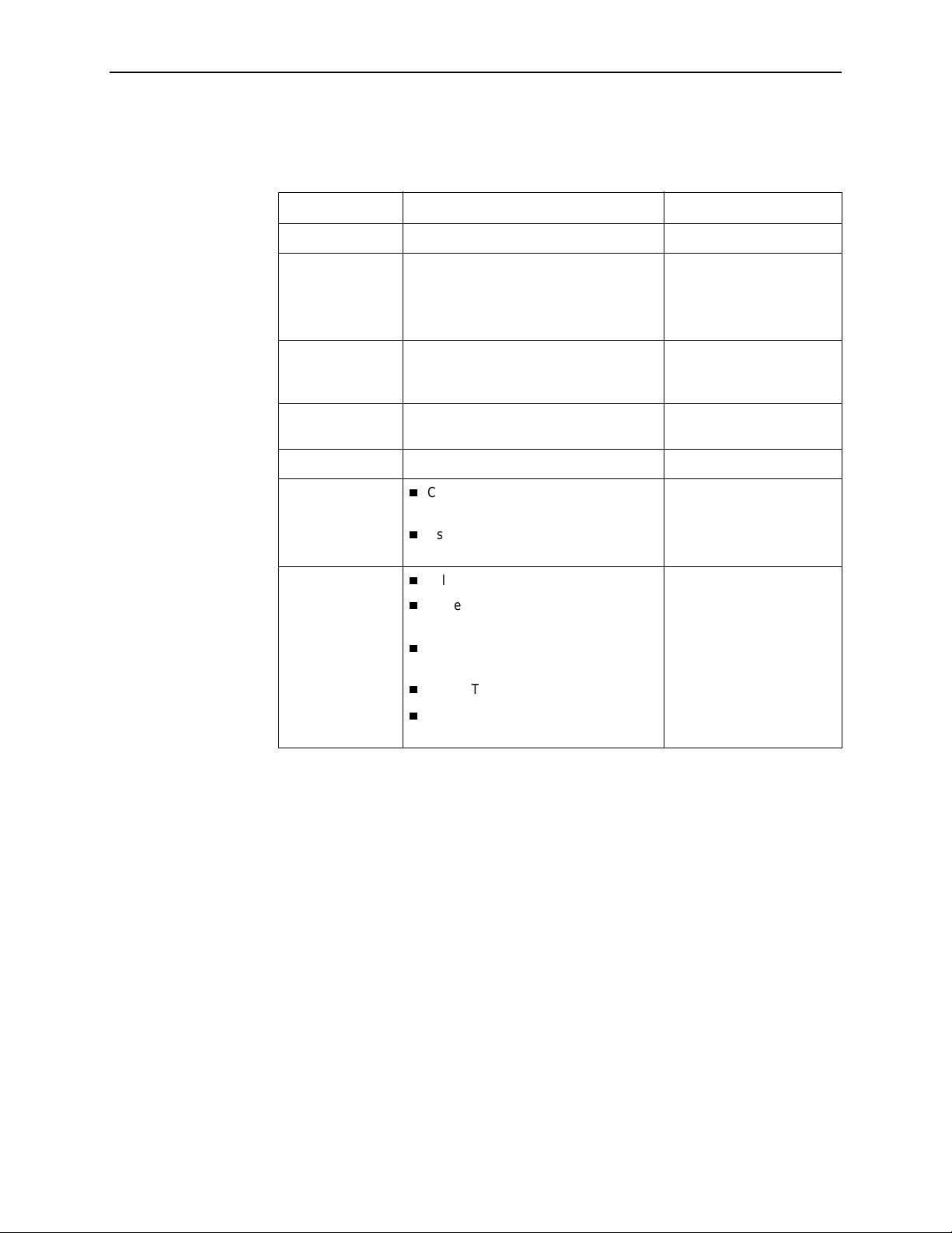
See Appendix A,
Configuration Options
, for a list and explanation of the
configuration options available
Select . . . To Access the . . . To Configure the . . .
Network Network Interface Options (Table A-1) DSL interf ace ports .
DSX-1
G.703
Copy P orts C opy Port Options (Table A-6) DSL network and DTE
System Options System Options (Table A-7) General system options of
System Clock System Clock Options (Table A-8) LTU system clock options.
Cross-Connect
Management and
Communication
DSX-1 Interface Options – Model 8777
(Table A-4)
G.703 Interface Options – Model 8779
(Table A-5)
Cross-Connect Mode Options –
Model 8779 (Table A-10)
Assi gn Time Slots Op tions
(Table A-11)
Telnet Session Options (Table A-12)
General SNMP Management
Options (Table A-13)
SNMP NMS Security Options
(Table A-14)
SNMP Traps Options (Table A-15)
Inband Management Channel
Options – Model 8779 (Table A-16)
DSX-1 interface ports
(Model 8777).
G.703 interface ports
(Model 8779).
interface ports by copying
options from port to port.
the unit.
DS1 and DS0
cross-connect ports.
Management support of
the unit through SNMP,
Telnet and the Inband
Management Channel.
3-6
May 2002 8700-A2-GB20-40
Page 29

Configuration Loader
3. Initial Startup and Configuration
The Configuration Loader screen allows you to upload configurations to and
download configurations from a TFTP server or the MCP FFS. T o access the
Configuration Loader screen, follow this menu selection sequenc e:
Main Menu→Configuration
main/configuration/config_loader
Model: 87xx
CONFIGURATION LOADER
→
Configuration Loader
Configuration File Name:
TFTP Server IP Address: IP
TFTP Transfer Direction: Download from Server
Destination: DSL
Start Transfer: Yes
Packets Sent: 0000000
Packets Received: 0000000
Bytes Sent: 0000000
Bytes Received: 0000000
Transfer Status: Transfer Pending
Activate new configuration? No
------------------------------------------------------------------------------Ctrl-a to access these functions, ESC for previous menu M
000.000.000.000 Clear
Clear
ainMenu Exit
Procedure
To upload or download a configuration:
1. Position the cursor in the Image File Name field. Type the name of the file to
be downloaded, or the name to be used for the file to be uploaded.
The filename may be a regular path name expression of directory names
separated by a forward slash (/) ending with the filename. The total path name
length can be up to 128 characters.
—
DOS machine:
If the TFTP server is hosted by a DOS machine, then
directory and filenames must consist of eight or less characters with an
optional suffix of up to three characters. The system will automatically
upload the configuration file and create directories and filenames, as
needed.
—
UNIX machine:
If your server is hosted by a UNIX machine, the
configuration file you name must already exist. It will not be created on the
UNIX system by the TFTP server. It is critical that you work with your
system administrator to plan the naming conventions for directories,
filenames, and permissions so that anyone using the system has read and
write permissions.
—
MCP FFS:
When uploading configuration files to the MCP FFS, the
directory and filename must be entered, otherwise the download will fail.
8700-A2-GB20-40 May 2002
3-7
Page 30

3. Initial Start up and Configuration
2. Position the cursor in the TFTP Server IP Address field. Enter the TFTP server
IP address or M1 for the MCP F FS.
The first three digits of the IP address cannot be 000 or greater than 223.
3. Position the cursor in the TFTP Transf er Dir ection field. Use the spacebar to
select Download from Server or Upload to Server .
4. For a Line Termination Unit (LTU), go to Step 5. For a Network Termination
Unit (NTU), position the cursor in the Destination field. Use the spacebar to
select a network destination for the TFTP server. Select DSL if the TFTP
server destination is the DSL link port or IMC (Internal Management Channel)
if the TFTP destination is the Management port of the MCC.
5. Position the cursor at the Start Transfer field. Use the spacebar to select Yes.
Press Enter.
When the data transfer is complete, the Transfer Status field changes to
Completed successfully
.
6. Position the cursor at the
select Yes to activate a new downloaded configuration. Press Enter.
Activate new configuration?
prompt and
NOTE:
Configuration options DSL Mode and T el net Session are
new configuration is loaded. You must change these settings with the
appropriate configuration menus after the new configuration is activated. See
Table A-7, System Options, and Table A-10, Cross-Connec t Mode Options –
Model 8779, in Appendix A,
Configuration Options
.
changed when a
not
3-8
May 2002 8700-A2-GB20-40
Page 31

Saving Configuration Options
When changes are made to the configuration options through the Configuration
Edit/Display branch, the changes must be saved to take effect. Use the S
or Save Configuration screen.
Procedure
To s ave configuration options changes:
1. Press Ctrl-a to switch to the function key and message area.
3. Initial Startup and Configuration
ave key
2. Select S
ave and press Enter.
NOTE:
When Exit is selected before Save, or Save has been selected from any menu
in the Configuration/Edit branch, a Save Configuration screen appears
requiring a Yes or No response.
main/config/saveprompt
Slot: 4 Model: 87xx
SAVE CONFIGURATION
Save Changes? No
WARNING:
An answer of “yes” will cause the system
to reset as if it had been powered off and on!
------------------------------------------------------------------------------Ctrl-a to access these functions, ESC for previous menu MainMenu Exit
Command Complete
If the Telnet Sess ion configuration option is changed, a message displays on the
Save Configuration screen warning that an answer of Yes will caus e the Telnet
session to disconnect. Do not answer Yes unless you are prepared to disconnect.
If the DSL Mode configuration option is changed, the Save Configuration screen
bears the warning that an answer of Yes will c ause the system to reset. Do not
answer Yes unless you are prepared to reset the unit.
If you s elect . . . Then . . .
Yes The configurat ion is saved.
No The Main Menu appears and ch anges are not saved.
8700-A2-GB20-40 May 2002
3-9
Page 32

3. Initial Start up and Configuration
Restoring Access to the User Interface
Improper configuration of the unit could render the user interface inaccessible. If
this occurs, access can be restored using the management card of the DSLAM.
Procedure
To reset the DSL Card using the DSLAM’s management card:
1. Follow this menu selection sequence:
Configuration→DSL Cards →Reset Slot
2. Enter
3. Enter
4. Enter Y if you want to clear NVRAM also, otherwise enter N.
5. Enter Y at the prompt to confirm.
NOTE:
When you enter Y, all data connectivity is interrupted.
Resetting the Device
If the user interface is functional and you would like to reset the card without
removing the card from the DSLAM, follow this procedure.
Procedure
To reset the card using the Control branch:
1. Follow this menu selection sequence:
DSL
Reset
Main Menu→Control→Reset Device
, where nn is the slot number for the DSL card you wish to reset.
nn
.
2. The message
3. Enter
3-10
May 2002 8700-A2-GB20-40
Yes
Are you sure?
.
appears.
Page 33

Disabling AutoRate
The AutoRate function is controlled from the Network Interface Options screen
and allows you to enable or disable the AutoRate feature. The AutoRate option is
only available if the unit is configured as an LTU.
To access the Network Interface screen, follow this menu selection sequence:
main/config/network
Slot: 4 Model: 87xx
Port: 1
NETWORK INTERFACE OPTIONS
Margin Threshold: –3db
Excessive Error Rate Threshold: 1E–5
AutoRate Enable
Max DSL AutoRate 144
3. Initial Startup and Configuration
Main Menu→Configuration→Current Configuration→Network
-------------------------------------------------------------------------------Ctrl-a to access these functions, ESC for previous menu M
S
ave
The AutoRate option defaults to Enable.
Procedure
To disable AutoRate:
1. Position the cursor in the AutoRate field and press the spacebar.
2. Enter a DSL Line Rate and press Enter.
Resetting AutoRate
The Reset AutoRate function of the Control branch causes the unit to repeat the
AutoRate sequence. The unit attempts to establish the DSL link at the highest rat e
(or the value of DSL Line Rate, which represents the AutoRate ceiling when
AutoRate is enabled). If the link fails, the next lower rate is tried until the link is
established.
ainMenu Exit
The AutoRate field toggles to Disable and the DSL Line Rate field appears.
To acc ess the Reset AutoRate screen, follow this menu selection sequence:
Main Menu→Control →Reset AutoRate
8700-A2-GB20-40 May 2002
3-11
Page 34

3. Initial Start up and Configuration
Downloading Firmware
The Download Code screen allows you to download firmware from a TFTP server
or MCP FFS. T o access the Download Code screen, follo w this menu selection
sequence:
Main Menu→Control →Download Code
main/control/download_code
Slot: 4 Model: 87xx
Port: 1
DOWNLOAD CODE
Image File Name: Clear
TFTP Server IP Address: IP
Destination: DSL
Immediately Apply Download: Yes
Start Transfer: No
Packets Sent: 0000000
Packets Received: 0000000
Bytes Sent: 0000000
Bytes Received: 0000000
Transfer Status: Transfer Pending
000.000.000.000 Clear
------------------------------------------------------------------------------Ctrl-a to access these functions, ESC for previous menu MainMenu Exit
Procedure
To download firm ware:
1. Position the cursor in the Image File Name field. Type the name of the file to
be downloaded.
The file name may be a regular path name expression of director y names
separated by a forward slash (/) ending with the file name. The total path
name length can be up to 128 characters.
2. Position the cursor in the TFTP Server IP Address field. Enter the TFTP server
IP address or M1 for the MCP F FS.
3. For an LTU, go to Step 4 . For an NTU, position the cursor in the Destination
field. Use the spacebar to select a network destination for the TFTP server .
Select one of the following:
— DSL if the TFTP server destination is the EOC.
— IMC if the TFT P de st ination is via the MC P.
4. Position the cursor in the Immediately Apply Download field. If you would like
the download to be effective immediately, select
3-12
May 2002 8700-A2-GB20-40
Yes
.
Page 35

3. Initial Startup and Configuration
5. Position the cursor at the Start Transfer field. Use the spacebar to select Yes.
Press Enter.
When the data transfer is complete:
— If you selected Yes in Step 4, the unit is reset.
— If you selected No in Step 4, the Transfer Status field changes to
Completed successfully
.
If you specified No (the default) in the Immediately Apply Download field in
Step 4 above, you must now apply the download.
main/control/apply_download
Slot: 4 Model: 87xx
Port: 1
APPLY DOWNLOAD
Switch To Code Revision A01.00.02: No
WARNING:
An answer of “yes” will cause the system
to reset as if it had been powered off and on!
------------------------------------------------------------------------------Ctrl-a to access these functions, ESC for previous menu M
Select: Yes, No LOS at Net, Pt 1
ainMenu Exit
Procedure
To appl y the downloaded fir mware:
1. Press the Escape key to return to the Control menu. Select Apply Download.
2. On the Apply Download screen, type
to reset the card and activate the
Yes
code.
Selecting Yes causes the ter mi nation unit to reset.
NOTE:
The termination unit has two flash memory banks to hold executable firmware.
You can switch between these two firmware versions by appl ying the firmware
listed on the Apply Download screen.
8700-A2-GB20-40 May 2002
3-13
Page 36

3. Initial Start up and Configuration
3-14
May 2002 8700-A2-GB20-40
Page 37

Cross-Connecting Ports
Overview
Configuration of the cross-connections consists of the following steps:
Determine how the ports will be connected and configured.
❑
On the Network Interface Options screen, enable the DSL ports that will be in
❑
the cross-connection if necessary. The ports are enabled by default.
On the DSX-1 or G.703 Interface Options screen, enable the DSX-1 or G.703
❑
ports that will be in the cross -c onnect ion.
For G.703, specify whether Time Slot 16 is used for signaling (voice mode).
4
On the System Clock screen, configure the system clock.
❑
On the Cross-Connect Mode screen:
❑
— Define all DS1 Bypass ports.
— Define all DS1 Cross-Connect ports.
— Define all DS0 Cross-Connect ports.
On the Assign Time Slots screen, configure the DS0 cross-connections.
❑
This chapter describes the use of the Cross-Connect Mode and Assign Time Slots
screens. See Appendix A,
configuration options presented on the other screens.
Examples in this chapter show screens for DSX-1 models. The principles of
cross-connection are the same for G.703 models.
IMPORTANT:
All DSL time slots are available for cross-connect regardless of DSL line
rate, but all time slots are available for data transport only if the DSL line
rate is the full rate (1552 for DSX-1 or 2064 for G.703). Configure only the
time slots intended for use.
Configuration Options
, for information about
8700-A2-GB20-40 May 2002
4-1
Page 38

4. Cross-Connecting Ports
Determining the Configuration
The Hotwire cross-connect system allows you to connect the DSX-1 or G.703
ports to the DSL por ts in a variety of ways:
DS1 Bypass mode
DSL interface.
DS1 Cross-Connect mode (8777)
to the DSL interface through cross-connect circuitry. Ports can be switched
through software.
DS1 Cross-Connect mode (8779)
connected to any DSL or G.703 interface. The entire DSL interface can be
connected to any DSL or G.703 interface through cross-connect circuitry.
Ports can be switched through software.
DS0 Cross-Connect mode (8777)
be connected to any time slot of any DSL interface. Time slots can be
individually allocated for voice or data.
DS0 Cross-Connect mode (8779)
be connected to any time slot of any G.703 or DSL interface. Any time slot of
any G.703 interface can be connected to any time slot of any G.703 or DSL
interface. Time slots can be individually allocated for voice or data.
The example below shows a DS0 cross-connection between DSX-1
Ports 1 and 2. DSX-1 Port 1 is dedicated to voice and Port 2 to data.
– The entire DSX-1 or G.703 interface is connected to the
– The entire DSX-1 interface is connected
– The entire G.703 interface can be
– Any time slot of any DSX-1 interface can
– Any time slot of any DSL interface can
4-2
May 2002 8700-A2-GB20-40
Page 39

Port 1
X
❏ Voice
❏ Data
Port 2
❏ Voice
X
❏ Data
DSX-1
G.703
DSX-1
G.703
DS0
Cross-Connect
DSL
DSL
4. Cross-Connecting Ports
Port 1
Port 2
Port 3
❏ Voice
X
❏ Data
Port 4
❏ Voice
X
❏ Data
Port 5
❏ Voice
X
❏ Data
Port 6
❏ Voice
X
❏ Data
Port 7
❏ Voice
X
❏ Data
Port 8
❏ Voice
X
❏ Data
DSX-1
G.703
DSX-1
G.703
DSX-1
G.703
DSX-1
G.703
DSX-1
G.703
DSX-1
G.703
DS1 Bypass
DS1 Bypass
DS1 Bypass
DS1 Bypass
DS1 Bypass
DS1 Bypass
DSL
DSL
DSL
DSL
DSL
DSL
Port 3
Port 4
Port 5
Port 6
Port 7
Port 8
99-16603
NOTES:
— Although the example shows ports dedicated to voice or data, a port can
be configured for both voice and data.
— For G.703 ports using Common Channel Signaling (CCS) that are in DS0
Cross-Connect mode, you must explicitly configure the cross-connections
for Time Slot 16 and related time slots.
You may find it useful to diagram your configuration. Appendix E,
Cross-Connection Worksheets
It also contains worksheets for documenting your time slot cross-connections
before you begin to configure them.
8700-A2-GB20-40 May 2002
, contains a skeleton diagram for this purpose.
4-3
Page 40

4. Cross-Connecting Ports
Setting the Cross-Connect Modes
To acc ess the Set Cross-Connect Mode screen, follow this menu selection
sequence:
Main Menu→Configuration→Current Configuration→Cross-Connect
→
Set Cross-Connect Mode
When the screen is first displayed, all ports are set to DS1 Bypass mode. In this
example, Ports 1 and 2 have been changed to
Ports 3 –8 have been changed to
DS1 Bypass. Unassigned
DS0 Cross-connect
appears next to
, and
Ports 1 and 2 bec ause time slots associated with the cross-conne ction have not
yet been assigned.
main/config/xconnect_mode
Slot: 18 Model: 8777
CROSS-CONNECT MODE
DSX-1 Port MODE DSL Port
1 DS0 Cross-connect
2 DS0 Cross-connect
3 DS1 Bypass
4 DS1 Bypass
5 DS1 Bypass
6 DS1 Bypass
7 DS1 Bypass
8 DS1 Bypass
Assign_DS0s
Unassigned
Unassigned
3
4
5
6
7
8
------------------------------------------------------------------------------Ctrl-a to access these functions, ESC for previous menu MainMenu Exit
S
ave Clear_All
4-4
May 2002 8700-A2-GB20-40
Page 41
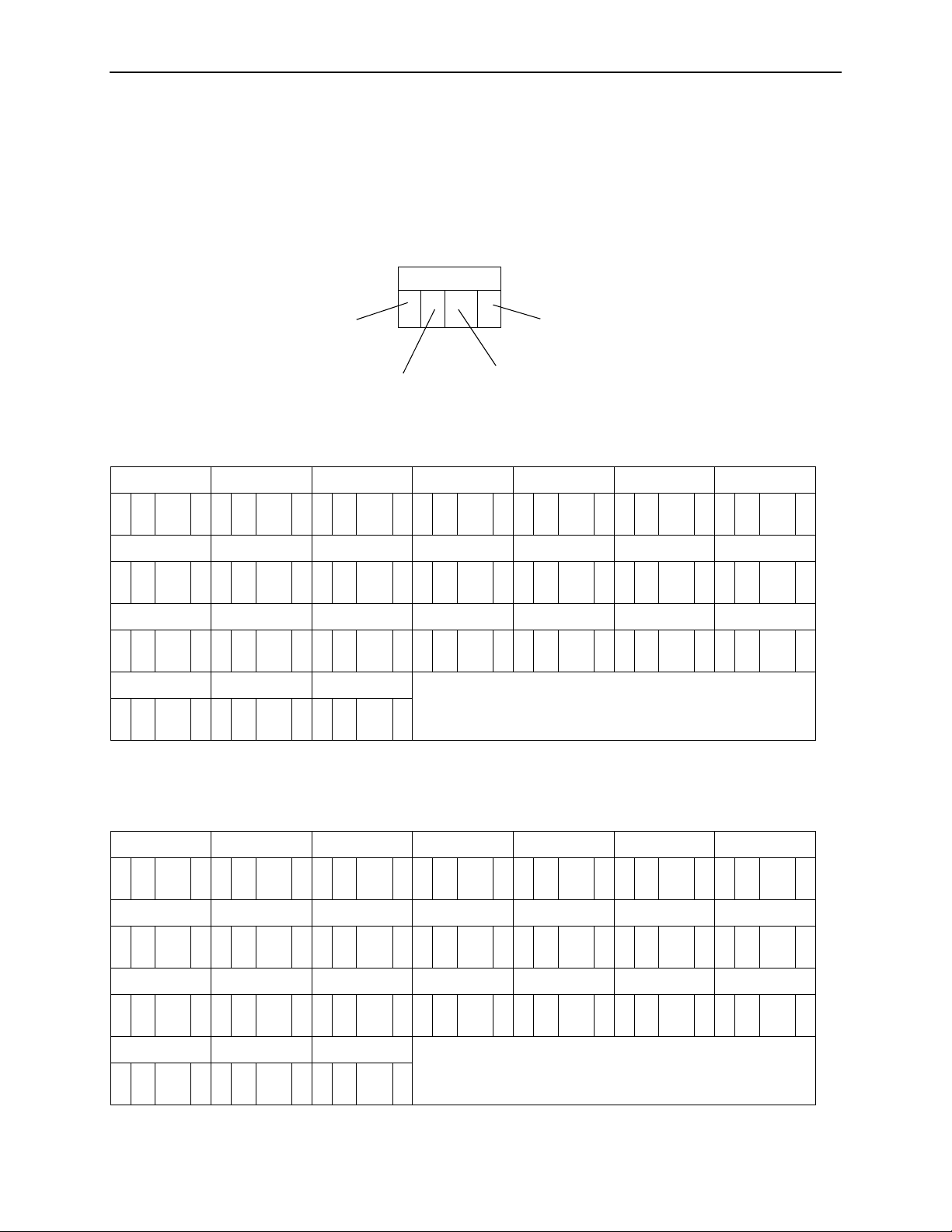
Assigning Time Slots
You may find it helpful to map your cross-connection assignments on a worksheet
before configuring them in the unit. In the following example, the worksheet for
DSX-1 Port 1, odd-numbered time slots from DSL Por t s 1 and 2 are assigned to
the time slots of DSX-1 Port 1 and configured for voice.
4. Cross-Connecting Ports
TS01
Port Type
(D = DSL
(X = DSX-1
Port Num ber
(1–8)
TS01 TS02 TS03 TS04 TS05 TS06 TS07
D
1 1 vD2 1 vD1 3 vD2 3 vD1 5 vD2 5 vD1 7 v
TS08 TS09 TS10 TS11 TS12 TS13 TS14
D
2 7 vD1 9 vD2 9 vD111vD211vD113vD213v
TS15 TS16 TS17 TS18 TS19 TS20 TS21
D
115vD215vD117vD217vD119vD219vD121v
TS22 TS23 TS24
D
221vD123vD223v
Time Slot
(1–24)
d (
Data
) or v (
Voice
)
DSX-1 Port 2 is configured for data and is connected to the even-numbered time
slots of DSL Ports 1 and 2:
TS01 TS02 TS03 TS04 TS05 TS06 TS07
D
1 2 dD2 2 dD1 4 dD2 4 dD1 6 dD2 6 dD1 8 d
TS08 TS09 TS10 TS11 TS12 TS13 TS14
D
2 8 dD110dD210dD112dD212dD114dD214d
TS15 TS16 TS17 TS18 TS19 TS20 TS21
D
116dD216dD118dD218dD120dD220dD122d
TS22 TS23 TS24
D
222dD124dD224d
8700-A2-GB20-40 May 2002
4-5
Page 42
4. Cross-Connecting Ports
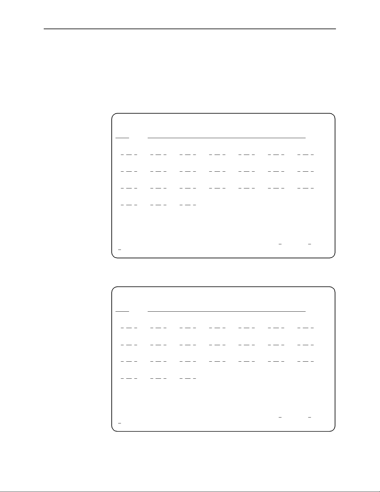
To access the Assign Time Slots screen, follow this menu selection sequence:
Main Menu→Configuration→Current Configuration→Cross-Connect
→
Assign Time Slots
When the screen is first displayed, port and time slot assignments are blank. The
following example shows the configuration for DSX-1 Port 1, transferred from the
worksheet.
main/config/cross_connect/timeslot
Slot: 18 Model: 8777
ASSIGN TIME SLOTS
Port: 1 DS0s to Allocate: Start TS: Assign To: D
DSX-1
TS01 TS02 TS03 TS04 TS05 TS06 TS07
D 1
01 v D 2 01 v D 1 03 v D 2 03 v D 1 05 v D 2 05 v D 1 07 v
TS08 TS09 TS10 TS11 TS12 TS13 TS14
07 v D 1 09 v D 2 09 v D 1 11 v D 2 11 v D 1 13 v D 2 13 v
D 2
TS15 TS16 TS17 TS18 TS19 TS20 TS21
D 1
15 v D 2 15 v D 1 17 v D 2 17 v D 1 19 v D 2 19 v D 1 21 v
TS22 TS23 TS24
21 v D 1 23 v D 2 23 v
D 2
Key: D = DSL, X = DSX-1, I = IBMC
d = data, v = voice
------------------------------------------------------------------------------Ctrl-a to access these functions, ESC for previous menu M
ave Clear_All
S
ainMenu Exit
The following example shows the configuration for DSX-1 Por t 2.
main/config/cross_connect/timeslot
Slot: 18 Model: 8777
ASSIGN TIME SLOTS
Port: 2 DS0s to Allocate: Start TS: Assign To: D
DSX-1
TS01 TS02 TS03 TS04 TS05 TS06 TS07
D 1
02 d D 2 02 d D 1 04 d D 2 04 d D 1 06 d D 2 06 d D 1 08 d
TS08 TS09 TS10 TS11 TS12 TS13 TS14
08 d D 1 10 d D 2 10 d D 1 12 d D 2 12 d D 1 14 d D 2 14 d
D 2
TS15 TS16 TS17 TS18 TS19 TS20 TS21
D 1
16 d D 2 16 d D 1 18 d D 2 18 d D 1 20 d D 2 20 d D 1 22 d
TS22 TS23 TS24
22 d D 1 24 d D 2 24 d
D 2
Key: D = DSL, X = DSX-1, I = IBMC
d = data, v = voice
------------------------------------------------------------------------------Ctrl-a to access these functions, ESC for previous menu M
ave Clear_All
S
ainMenu Exit
4-6
May 2002 8700-A2-GB20-40
Page 43

4. Cross-Connecting Ports
When the Cross-Connect Mode screen is displayed now,
appears next to
1,2
DSX-1 Ports 1 and 2 bec ause time slots associated with the cross-connec tion
have been assigned.
main/config/xconnect_mode
Slot: 18 Model: 8777
CROSS-CONNECT MODE
DSX-1 Port
1 DS0 Cross-connect 1,2
2 DS0 Cross-connect
3 DS1 Bypass
4 DS1 Bypass
5 DS1 Bypass
6 DS1 Bypass
7 DS1 Bypass
8 DS1 Bypass
Assign_DS0s
------------------------------------------------------------------------------Ctrl-a to access these functions, ESC for previous menu M
S
ave Clear_All
MODE DSL Port
1,2
3
4
5
6
7
8
ainMenu Exit
8700-A2-GB20-40 May 2002
4-7
Page 44

4. Cross-Connecting Ports
4-8
May 2002 8700-A2-GB20-40
Page 45

IP Addressing
Selecting an IP Addressing Scheme
Your IP addressing scheme depends in part whether the management card
controllin g the chassis is r un ning IP Conse rvative software.
Configurations Not Running IP Conservati ve Software
In a configuration not running IP Conservative software, the NTU’s network
interface IP address is assigned through the peer IP address of the LTU’s Network
Interface menu.
5
The termination unit is assigned an IP address and subnet through the DSLAM’s
Configuration →DSL Cards →Set IP Address
assigned, you can use the AT I to assign:
Peer IP addresses to the DSL ports. These addresses are used as the IP
addresses of the remote units, and must be in the same subnet as the DSLAM
management card. See Table A-1, Network Interface Options, in Appendix A,
Configuration Options
An IP address for each NMS to act as a trap manager. See Table A-15, SNMP
Traps Options, in Appendix A,
.
Configuration Options
menu. Once the address is
.
8700-A2-GB20-40 May 2002
5-1
Page 46
5. IP Addressing
All Configurations
The NTU obtains its IP address when the PPP link is established over the EOC.
Use the A T I to assign:
An IP address for each NMS. See Table A-14, SNMP NMS Secu rity Options,
in Appendix A,
An IP address for the TFTP server you wish to use to upload and download
configurations. See
Configuration Options
Configuration Loader
and Configurations Using TFTP
.
in Chapter 9,
Transferring Firmware
, and the documentation for your TFTP ser ver.
Review the following information in preparation for selecting an IP addressing
scheme.
Any legal host address is allowed for a given subnet. The address choice
within the subnet is arbitrary.
A single route to a subnet is all that is needed to reach every device on a
subnet. The unit’s routing table supports a maximum of 20 routes.
IP Addressing Example
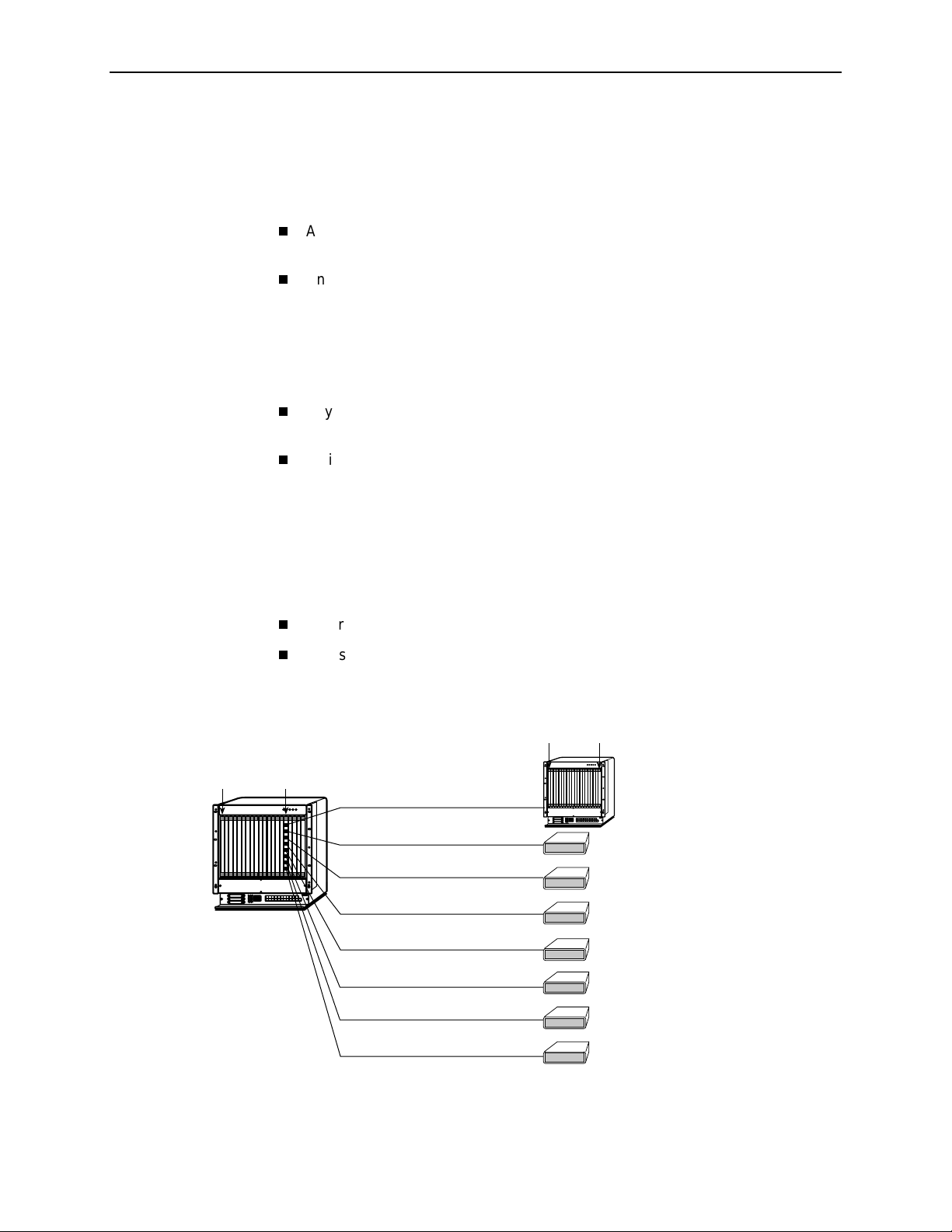
Figure 5-1, Peer IP Address Assignments, shows IP addressing in a typical
network. Note that the Peer IP Address:
Refers to the IP address of the unit configured as an NTU.
Is assigned by the LTU.
MCC
MCC Backplane
Address = 126.35.1.1
MCC Backplane
Mask = 255.255.255.0
LTU Backplane
Address = 126.35.1.16
LTU
87xx
Peer IP Address = 126.35.1.32
Peer IP Address = 126.35.1.33
Peer IP Address = 126.35.1.34
Peer IP Address = 126.35.1.35
DSLAM
Peer IP Address = 126.35.1.36
Peer IP Address = 126.35.1.37
Peer IP Address = 126.35.1.38
Peer IP Address = 126.35.1.39
Port 1
Port 2
Port 3
Port 4
Port 5
Port 6
Port 7
Port 8
MCC
DSLAM
NTU
MCC Base
Address = 126.35.50.1
MCC Base Subnet
Mask = 255.255.255.0
79xx
NTU Backplane
Address = 126.35.50.17
79xx
79xx
79xx
79xx
79xx
79xx
99-16617
Figure 5-1. Peer IP Address Assignments
5-2
May 2002 8700-A2-GB20-40
Page 47

Security
Overview
6
The Hotwire Termination Unit in IP Complex mode provides several methods of
limiting user access to the AT I through option settings. You can:
Enable the Telnet Login Required option.
Limit the access by setting a Session Access Level option of Operator for the
Telnet Session.
Disable the access with the Telnet Session option.
See Table A-12, Telnet Session Options, in Appendix A,
For informat ion on conf igur ing user accoun ts in IP Conser vative mode, see the
Hotwire Management Communications Controller (MCC) Card, IP Conservative,
User's Guide
.
Configuration Options
.
8700-A2-GB20-40 May 2002
6-1
Page 48

6. Security
ATI Access Levels
The Hotwire Termination Unit has two access levels: Administrator and Operator.
The access level determines what functions are accessible, as shown in Table 6-1,
Access Levels.
Table 6-1. Access Levels
A TI Access to Menu Functions Administrator Operator
Status Read-Only Read-Only
Test Full A ccess No Access
Config ur at io n Full Acce s s Read-Only
Control Full Access No Access
Access levels can be applied to Login IDs and Telnet sessions. When access is
through Telnet and a login is required for Telnet, the effective access level is the
more restrictive of the Telnet session access level or the login access level. (See
Table A-12, Telnet Session Options, in Appendix A,
Configuration Options
.)
When an access level of Operator is applied to Telnet sessions, a Login ID
with Administrator authority is effectively reduced to Operator.
possible to change configuration options, and full access can be restored only by
reloading factory defaults. (See
Chapter 3,
Initial Startup and Configuration
Restoring Access to the User Interface
.)
It is no longer
in
6-2
May 2002 8700-A2-GB20-40
Page 49

Creating a Login
6. Security
Logins apply to Telne t acces s directly to the ATI of the Hotwire Termination Unit.
The Administer Logins menu option is not presented when you access the unit
through the management card of the DSLAM and when in IP Conservative mode.
Six login ID/password combinations are available. Each Login ID and Password
must be unique and include an access level.
Procedure
1. To cr eate a login record, follow this menu selection sequence:
Main Menu→Control→Administer Logins
main/control/admin_logins
Slot: 4 Model: 87xx
ADMINISTER LOGINS Page 1 of 1
Login ID: newuser
Access Level: Administrator
Are You Sure? Yes
------------------------------------------------------------------------------- ESC for previous menu M
ave PgUp PgDn New Delete
S
ainMenu Exit
2. Select New and press Enter. The Login Entry screen is displayed.
main/control/admin_logins
Slot: 4 Model: 87xx
LOGIN ENTRY
Login ID: newuser
Password: e34t136
Re-enter Password: e34t136
Access Level: Administrator
WARNING
New logins will not become permanent until saved
through the “ADMINISTER LOGINS” screen!
-------------------------------------------------------------------------------Ctrl-a to access these functions ESC for previous menu M
S
ave PgUp PgDn New Delete
8700-A2-GB20-40 May 2002
ainMenu Exit
6-3
Page 50

6. Security
3. Create the login by entering the following fields. Login IDs and passwords are
case-sensitive.
On the Login Entry
screen, for the . . . Enter . . .
Login ID 1 to 10 ASCII printable characters (hex21 t hrough 7E).
Blanks are not allowed.
Pass w ord 1 to 10 ASCII printable characters that can consist of 0–9,
a–z, A–Z, # (pound), . (period), – (dash), and / (slash).
Re-enter Password 1 to 10 ASCII printable characters that can consist of 0–9,
a–z, A–Z, # (pound), . (period), – (dash), and / (slash).
Access Level Administrator, Operator
NOTE:
Assign at least one Administrator-level Login ID . Full access is necessary
to make configuration option changes and administer logins.
Deleting a Login
4. Press Ctrl-a to switch to the function keys area below the dotted line. Select
S
ave and press Enter.
5. Press Ctrl-a to switch to the screen function key area below the dotted line.
Select S
6. When Save is complete,
ave and press Enter.
Command Complete
appears at the bottom of the
screen.
7. If additional logins are required, repeat Steps 3 through 5.
8. When all logins are entered, press Esc to return to the Administer Logins
screen.
9. Select S
ave and press Enter.
Procedure
1. To del ete a login record, follow this menu selection sequence:
Main Menu→Control→Administer Logins
2. Select Pg Up or PgDn and press Enter to page through login pages/records
until you find the one to be deleted.
3. Once the correct record is displayed, select Del
4. To com plet e the delete action, select S
When the deletion is complete,
Command Complete
ave and press Enter.
ete and press Enter.
appears at the bottom
of the screen. The number of login pages /records reflects one less record,
and the record following the deleted record appears.
6-4
May 2002 8700-A2-GB20-40
Page 51

Controlling SNMP Access
There are three methods for limiting SNMP access.
Disable the SNMP management option. Refer to Table A-13, General SNMP
Management Options, in Appendix A,
Assign SNMP community names and access types.
Limit SNMP access through validation of the IP address of each allowed
SNMP manager.
Assigning SNMP Community Names and Access Types
The unit can be managed by an SNMP manager suppor t ing SNMP. The
community name must be supplied by an external SNMP manager accessing an
object in the MIB.
To def ine SNM P com munity name s, follow this menu selection sequence:
Configuration Options
6. Security
.
Main Menu→Configuration→Current Configuration
Management and Communication→General SNMP Management
Refer to Table A-13, General SNMP Mana gem ent Options, in Appendix A,
Configuration Options
Enable SNMP Management.
Assign the SNMP community names of the SNMP Managers that are allowed
to access the unit’s Managem ent Information Base (MIB).
Specify Read or Read/Write access for each SNMP community name.
, to:
Limiting SNMP Access through the IP Addresses of the Managers
The unit provides an additional level of security through validation of the IP
addresses.
The SNMP Management option must be enabled. T o control SNMP access with IP
addresses, follow this menu selection sequence:
Main Menu→Configuration→Current Configuration
Management and Communication→SNMP NMS Security
Refer to Table A-14, SNMP NMS Security Options, in Appendix A,
Options
. The SNMP access can be limited by:
→
→
Configuration
Enabling NMS IP address checking.
Add each IP address and access level.
NOTE:
Do not change or delete the IP address or access level of the NMS performing
the sets or enable IP address checking prior to adding the NMS to the table.
8700-A2-GB20-40 May 2002
6-5
Page 52

6. Security
6-6
May 2002 8700-A2-GB20-40
Page 53

Monitoring and Troubles hooting
What to Monitor
This chapter presents information on how to monitor termination unit status,
assess performance, and diagnose problems as described in the following
sections:
7
Viewing System and Tes t Statu s
—
Health and Status Messages
—
Self-Test Results Messages
—
Test Status Messages
Device Messages
Performance Statistics
—
Viewing Network Error Statistics
—
Viewing Network Performance Statistics
—
Viewing DSX-1 Performance Statistics
—
Viewing DSX-1 Performance Statistics
—
Viewing G.703 Performance Statistics
Viewing LED Status
Front Panel LEDs
Changing the Meaning of the PORTS LEDs
Troubleshoot ing
on page 7-10
on page 7-11
on page 7-22
on page 7-24
on page 7-25
on page 7-2
on page 7-25
8700-A2-GB20-40 May 2002
7-1
Page 54

7. Monitoring and Troubleshooting
V iewing System and Test Status
To view System and Test Status information, follow this menu selection sequence:
Main Menu→Status→System and Test Status
main/status/system
Slot: 2 Model: 87xx
SYSTEM AND TEST STATUS Page 1 of 1
HEALTH AND STATUS SELF-TEST RESULTS TEST STATUS
------------------------------------------------------------------------------LOS at Net, Pt
OOF at Net, Pt
EER at Net, Pt n Net DSL Failed, Pt n RLB Test Active, Pt
LOS at DSX-1 Pt n DSX-1 Pt Failed, Pt n Lamp Test Active
Net Margin Threshold, Pt
Device Failed
Download Failed
n
CPU Failed No Test Active
n
yyyyyyyy
Passed
Device Failed LLB Test Active, Pt
n
Memory Failed DLB Test Active, Pt
n
n
n
------------------------------------------------------------------------------ ESC for previous menu MainMenu Exit
The System and Test Status screen has three sections:
Health and Status
– Displays messages in priority order (highest to lowest).
Refer to T able 7-1, Health and Status Messages.
Self-Test Results
– Results of the Diagnostic test run on the device itself.
Refer to Table 7-2, Self-Test Results Messages.
Test Status
– Curr e n tly acti ve tests. Refer to Table 7-3, Test Status
Messages.
7-2
May 2002 8700-A2-GB20-40
Page 55

Health and Status Messages
The following messages appear in the first column of the System and Test Status
screen. The highest priority Health and Status message also appe ars on all ATI
screens on the bottom right.
Table 7-1. Health and Status Messages (1 of 4)
Message What Message Indicates What To Do
7. Monitoring and Troubleshooting
AIS at DSX-1,
n
Pt
AIS at G.703,
Pt
n
Device Failed
yyyyyyyy
Download Failed A firmware download was
EER at DSX-1,
n
Pt
EER at G.703,
n
Pt
An AIS (Alarm Indication
Signal) is being received by
the DSX-1 interface.
An AIS is being received by
the G.703 interface.
An internal error has been
detected by the operating
software.
the 8-digit hexadecimal
failur e code.
interrupted.
An Excessive Error Rat e
(EER) condition has been
detected on the DSX-1
interface.
An EER condition has been
detected on the G.703
interface.
yyyyyyyy
indicates
A fault exists in the network
connected to the DSX-1 port.
Contact network provider.
A fault exists in the network
connected to the G.703 port.
Contact network provider.
1. Provide the 8-digit failure
code sh ow n (
your service representative.
2. Reset the unit to clear the
condition and message.
Ensure that the file e xi sts on th e
TFTP server. Repeat the
download.
1. Verify the attached
equipment coding i s
compatible.
2. Verify the clock
configuration.
3. Contact network pr ovider.
1. Verify that the network cable
is securely attached at both
ends.
2. Verify the attached
equipment coding i s
compatible.
3. Verify the G.703 line
termination is configured
correctly.
4. Contact network pr ovider.
yyyyyyyy
) to
n
EER at Net, Pt
Fallba ck R ate,
n
Pt
8700-A2-GB20-40 May 2002
An EER condition has been
detected on the network
interf ace at Port
condition is cleared when the
error rate falls below the
threshold value currently
configured.
The LTU, set to AutoRate
enable, synchronized at a
lower rate when the line was
restored after an LOS.
n
. The
1. Check the Network
Performance Statistics
screen for possible line
impairments.
2. Set the unit to run at a lower
DSL line rate.
Reset AutoRate, or run at a
fixed r ate.
7-3
Page 56

7. Monitoring and Troubleshooting
Table 7-1. Health and Status Messages (2 of 4)
Message What Message Indicates What To Do
IBMC Not Supported
on MCP
IP Misma tc h, Pt
LOF at DSX-1,
n
Pt
LOF at G.703,
n
Pt
n
The Inband Management
Channel (IBMC) is enabl ed,
but the MCP card does not
support Inband Management.
The NTU and the LTU are
operating in dif ferent NMS
management modes: one is
in IP Conservat ive mode and
one is not.
An LOF (Loss Of Frame)
condition has been detected
on the DSX-1 interf ace. LOF
is declared when an O O F
state exists longer than 2.5
seconds.
An LOF condition has been
detected on the G.703
interface. LOF is declared
when any three consecutive
frame synchronization bits
are incorrect, frames not
containing the frame
alignment s ignal a re r eceiv ed
with an error three times
consecutively , or, for CRC-4
framing, CRC multifr am e bit
alignment fails.
1. Disable the Inband
Management Channel .
2. Download the MCP with a
version of code that supports
inband management.
In a DSLAM-to-DSLAM
configuration, use the same
software in the managem ent
cards of both DSLAMs.
1. Verify that the network cable
is securely attached at both
ends.
2. Verify the unit’s line framin g
and line coding are
compatible with the attached
equipment.
3. Contact network pr ovider.
1. Verify that the network cable
is securely attached at both
ends.
2. Verify that the units line
framing and line coding are
compatible with the attached
equipment.
3. Contact network pr ovider.
LOS at DSX-1,
n
Pt
LOS at G.703,
n
Pt
7-4
May 2002 8700-A2-GB20-40
An LOS (Loss Of Signal)
condition has been detected
on the DSX-1 interf ace. No
signal is being received on
n
. LOS is decla red when
Port
175 consecutive zeros are
received.
An LOS condition has been
detected on the G.703
interf ace. No signal is being
n
received on Port
declared when 175
consecutive pulse
transmissions are received
with no pulse transitions.
. LOS is
1. Verify that the network cable
is securely attached at both
ends.
2. Contact network pr ovider to
troubleshoot the line.
1. Verify that the network cable
is securely attached at both
ends.
2. Contact network pr ovider to
troubleshoot the line.
Page 57

7. Monitoring and Troubleshooting
Table 7-1. Health and Status Messages (3 of 4)
Message What Message Indicates What To Do
LOS at Net, Pt
Mismatch Rate, Pt
Net Margin Threshold,
n
Pt
NTU/LTU Mismatch,
Pt
n
n
n
An LOS (Loss Of Signal)
condition has been detected
on the network interface. No
signal is being received on
n
, possibl y du e to a l ocal
Port
network problem.
The LTU, set to a fixed DSL
rate, is attemp ting to operate
at a rate the NTU is not
capable of.
The signal-to-noise margin
has dropped below the
configured threshold.
The NTU is not compatible
with th e LTU.
1. Verify that the network cable
is securely attached at both
ends.
2. Verify proper NTU and LTU
configuration.
3. Contact network pr ovider to
troubleshoot the line.
Set the LTU to a compatible r ate
or replace the NTU.
1. Check the Network
Performance Statistics
screen for possible line
impairments.
2. Set the unit to run at a lower
DSL line rate.
3. Reconfigure the margin
threshold (if appropriate).
4. Contact network pr ovider to
troubleshoot the line.
Contact network provider.
NTU TS16 Not
Supported
OOF at N e t, P
Payload Rate
Mismatch Pt
n
The LTU is configured f or
TS16 signaling and the NTU
is not configured to support
TS16 signaling.
n
An Out Of Frame (OOF)
condition has been detected.
An OOF condition i s declared
when 2 out of 4 frame
synchronization bits are in
error.
The endpoint device is an
EIA-530-A model that does
not support the configured
EIA-530-A payl oad rate.
1. Verify endpoint is a G.703
product. EIA-530-A products
do not support signaling.
2. Replace endpoint or
reconfigure TS16 to data.
1. Check the Transmit Clock on
the unit and attached
equipment.
2. Set the unit to run at a lower
DSL line rate.
3. Contact network pr ovider.
Reconfigure the EIA-530
Payload Rate configuration
option to an acceptable rate.
Network Interface Options
See
in Appendix A,
Menu
Configuration Options
acceptable rates.
for
8700-A2-GB20-40 May 2002
7-5
Page 58

7. Monitoring and Troubleshooting
Table 7-1. Health and Status Messages (4 of 4)
Message What Message Indicates What To Do
Primary Clock Failed,
Pt
n
Primary System Clock
Failed
RAI at G.703,
n
Pt
Secondary System
Clo ck Failed
A failure has occurred in the
primary clock source for the
DSX-1 or G.703 port.
A failure has occurred in the
clock common to all
cross-connect circuitry.
An RAI (Remote Alarm
Indication ) si gnal is being
received by the G.703
interface.
A failure has occurred in the
fallback clock for the system
clock.
1. Verify that the network cable
is securely attached at both
ends.
2. Verify the clock configuration
on the unit and attached
equipment.
3. Contact network pr ovider.
Contact your service
representative.
1. Check the status of the
attached device.
2. Verify that the Line Coding,
Line Framing, and Time Slot
16 configurat ion options
selected are compat ible with
the connected G.703
equipment’s configurations.
G.703 Interface Options
See
(Model 8779)
Configuration Options
Contact your service
representative.
in Appendix A,
.
System Operational There are no problems
detected.
Yellow Alarm at
DSX-1, Pt
n
A Yellow Alarm Indication
signal is being received by
the DSX-1 interface.
No action is needed.
1. Verify that the unit’s line
framing and line coding are
compatible.
2. Contact network pr ovider.
7-6
May 2002 8700-A2-GB20-40
Page 59

Self-Test Results Messages
The results of the last power-on or reset self-test appear in the middle column of
the System and Test Status screen.
Table 7-2. Self-Test Results Messages (1 of 2)
Message What Message Indicates What To Do
7. Monitoring and Troubleshooting
CPU Fail The Central Processing Unit
failed internal testing.
CPU CPLD Fail The Complex Progr am m able
Logic Device serving the
Central Processing Unit
failed.
n
Data Path Fail, Pt
DeviceFailed One or more of the unit’s
DSL
x
x
Fai l
n
n
Fai l
Framer
DSL xcvr Fail, Pt
DSX-1 Failed, Pt
DTE
Framer
The port shown failed to loop
data on the full data path test.
integrat ed circuits has failed
device-level testing.
The DSL framer f or Ports
1–4 (Framer A) or
5–8 (Framer B) failed.
The DSL transceiv er failed
n
on Port
The unit failed to internally
loop data on the DSX-1
Port
The DTE framer for Ports
1–4 (Framer A) or
5–8 (Framer B) failed.
.
n
.
1. Reset the unit and try again.
2. Call your service
representative for
assistance.
DTE LIU
EEPROM Fail The unit faile d Elec trical ly
Failure
x
Fail The DTE Line Interface Unit
for Ports 1–2 (LIU A),
3–4 (LIU B), 5–6 (LIU C), or
7– 8 (LIU D) failed.
Erasable Pro grammable
Read-Only Memory
verification.
xxxxxxxx
An internal failure occurred.
(xxxxxxxx
8-digit hexadecimal failure
code for use by servic e
personnel.)
8700-A2-GB20-40 May 2002
represents an
Record the failure code
and contact your service
representative.
7-7
Page 60

7. Monitoring and Troubleshooting
Table 7-2. Self-Test Results Messages (2 of 2)
Message What Message Indicates What To Do
FPGA Failed The Field Programmable
Gate Array servi ng all ports
failed.
G.703 Failed, Pt 1 The unit failed to loop data on
n
the G.703 on Port
Memory
Test
n
Fail
Passed No errors were detected. No action is needed.
PLD Failed, Pt
TSI CPLD Fail The Complex Programmable
TSI Fail The Timeslot Interchanger
n
The unit failed memory data
verifica ti on (Test 1) or
memory address verification
(Test 2).
An error was detect ed in a
Programmable Logic Device.
Logic Device serving the
Timeslot Interchanger failed.
failed.
.
1. Reset the unit and try again.
2. Call your service
representative for
assistance.
1. Reset the unit and try again.
2. Call your service
representative for
assistance.
7-8
May 2002 8700-A2-GB20-40
Page 61

Test Status Messages
7. Monitoring and Troubleshooting
The Test Status messages in the following table appear in the right column of the
System and Test Status screen.
Table 7-3. Test Status Mess ages
Test Status Message Meaning
511 Test Active, Pt
DLB Test Active, Pt
Lamp Test Activ e The Lamp Test is active, causing the LEDs on the front panel
LLB Test Active, Pt
No Test Active No tests are currentl y runni ng.
Remote LLB Dn
Active, Pt
Remote LLB Up
Active, Pt
RLB Test Active, Pt
Telco LLB Active, Pt
Telco PLB Active, Pt
n
n
For further information on testing, refer to Chapter 8,
A 511 Test and Monitor is active on the DSL Port n network
n
interface.
A Data Terminal Loopback test is active on Port n.
n
to light.
A network Line Loopback test is active on Port n.
n
A Remote Line Loopback Down command is being sent.
A Remote Line Loopback Up comm and is being sent.
A network Repeater Loopbac k test is active on Port n.
n
A Telco-initiated Line Loopback is active on the specified
n
DSX-1 port.
A Telco-initiated Payload Loopback is active on the specified
n
DSX-1 port.
Testing
.
8700-A2-GB20-40 May 2002
7-9
Page 62
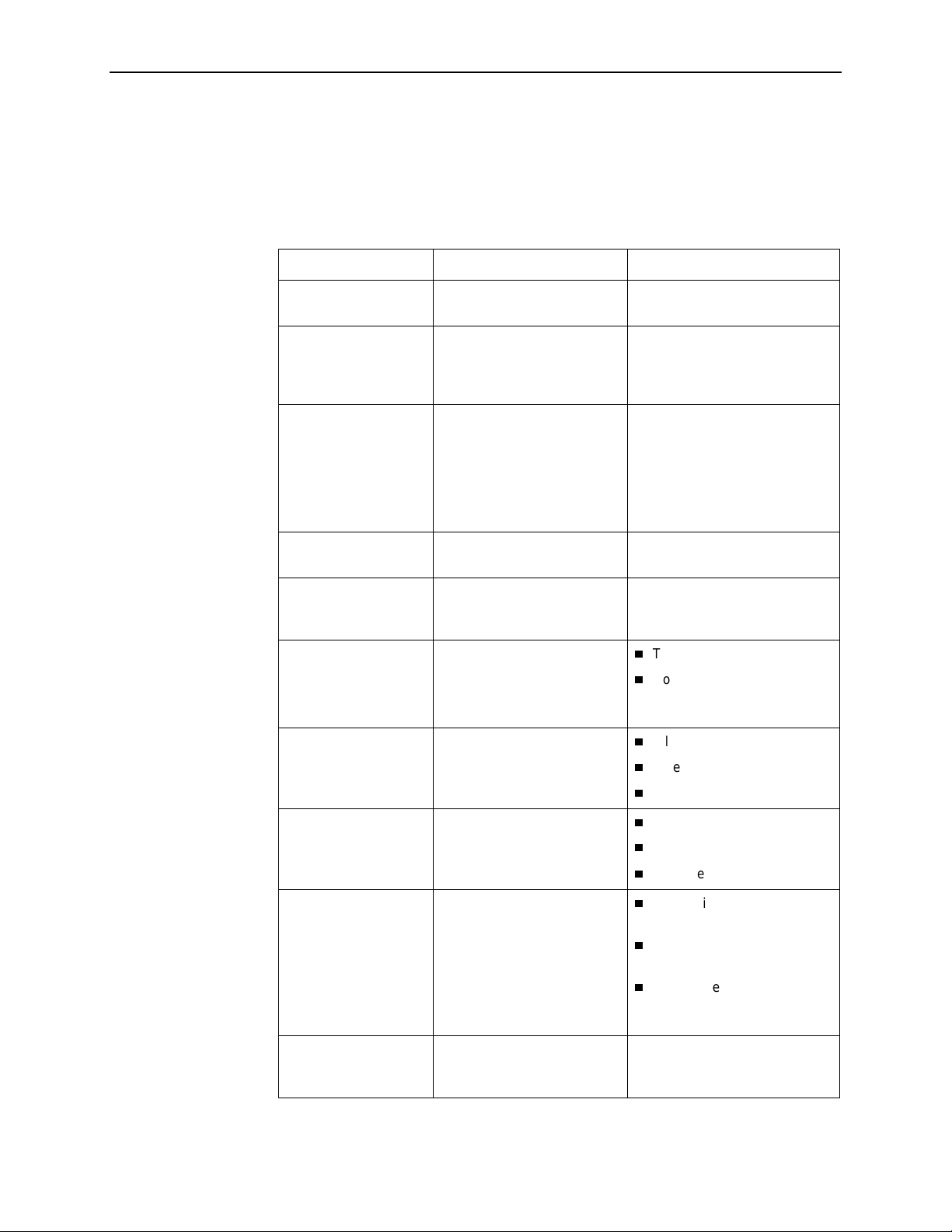
7. Monitoring and Troubleshooting
Device Messages
The Device Messages in Table 7-4, listed in alphabetical order, may appear in the
messages area at the bottom of the ATI screens.
Table 7-4. Device Messages (1 of 2)
Device Message What Message Indicates What To Do
0.0.0.0 is an invalid
IP address
Access level is
Operator.
Configuration is
read-only.
Cannot Save – no
Login IDs with Access
Administrator
Command Complete Action requested has
Invali d Character (
Invali d Password Login is required and an
Invalid – Send Pattern
Already Active
An IP address of all zeros
was entered.
The operator requested that
configuration options be
loaded, but does not have
authority to edit them .
All of the login IDs being
saved have an access level
below Administrator.
successfully completed.
x
) A nonprintable ASCII
x
character (
entered.
incorrect password was
entered; access is denied.
A pattern test was already in
progress when the Start field
was selected.
) has been
Enter a valid, non-zero IP
address.
If confi gurat ion op tions ar e to be
edited, use a Login ID that has
Administrator authority.
Change the access level of at
least one Login ID to
Administrator so that
configurat ion changes can be
made. (Operator-level users
cannot make configuration
changes.) Save the Login IDs.
No action is needed.
Re-enter inf ormation usi ng v ali d
characters.
Try again.
Contact your system
administra tor to verify your
password.
Allow test to contin ue.
Select another test.
Stop the test.
Invalid –
Active
Invalid Test
Combination
IP address not in
MCC subnet
nnn.nnn.nnn.nnn
7-10
May 2002 8700-A2-GB20-40
[Test]
Already
The described test was
already in progress when
another selection was made.
A loopback or pattern test
was in progress when Start
was selected to start another
test, or was active on the
same or another interface
when Start was selected.
The Peer IP address
specified is not in the same
subnet as the MCC.
Allow test to contin ue.
Select another test.
Stop the test.
Wait unti l other test ends and
message clears.
Abort all tests from the Test
menu screen.
Stop the test from the same
screen the test was started
from.
Enter an IP address that is in
the same subnet as the MCC.
Page 63

7. Monitoring and Troubleshooting
Table 7-4. Device Messages (2 of 2)
Device Message What Message Indicates What To Do
Limit of six Login IDs
reached
No Security Record s to
Delete
Pass w ord Matching
Error – Re-enter
Password
Please Wait Command takes longer than
Test Active A test is running and no
An attempt to enter a new
login ID was made, and the
limit of six login/password
combinations has been
reached.
Delete was select ed from th e
Administer Login scr een, and
no security records had been
defined.
Password entered in the
Re-enter Password field of
the Administer Log ins screen
does not match what was
entered in the Password
field.
5 seconds.
higher priority health and
status message s exist.
1. Delete another
login/password combination.
2. Re-enter the new login ID.
No action is needed.
Enter a security record.
Try again.
Contact your system
administra tor to verify your
password.
Wait until message clears.
Contact service provider if
test initiated by the network.
Wait until the other test ends
and message clears.
Cancel all tests from the Test
screen.
Stop the test from the same
screen the test was started
from.
Performance Statistics
Perf ormance statistics can assist you in determining the duration of specific
conditions and provide a historical context for problem detection and analysis.
Statistics are maintained for up to 96 15-minute intervals (24 hours).
Select a port to view the performance statistics. Port 1 is the default.
Use the applicable virtual function keys to page through the intervals and clear
statistics.
Select PgUp or PgDn to view more statistics.
Select ClrN ear or ClrFar to clear the near- and far-end statistics to zero.
For DSX-1 and G.703 statistics, select ClrStats to clear all statist ics to zero.
8700-A2-GB20-40 May 2002
7-11
Page 64

7. Monitoring and Troubleshooting
Viewing Network Error Statistics
The terminal unit maintains error statistics on the network DSL interface for each
port.
To view Network Error Statistics, follow this menu selection sequence:
Main Menu→Status→Perf ormance Statistic s→Network Error Statistics
main/status/performance/net_error
Slot: 4: Model: 87xx
Port: 2 NETWORK ERROR STATISTICS
Current Interval Timer: 002 Error Events Counter: 0034
-------------------------------------------------------------------------------
---ES--- ---SES--- --FEBE-- -Complete Near Far Near Far Near Far Near Far
Current Int: 000 000 000 000 000 000 Yes No
Interval 01
Interval 02 000 000 000 000 000 000 Yes Yes
Interval 03 000 000 000 000 000 000 Yes Yes
Interval 04
Interval 05 000 000 000 000 000 000 Yes Yes
Interval 06 000 000 000 000 000 000 Yes Yes
Interval 07
000 000 000 000 000 000 Yes Yes
000 000 000 000 000 000 Yes Yes
000 000 000 000 000 000 Yes Yes
Worst Interval: 24 09 14 08 18 18
Near Tot(valid): 00010 00000 00000
Far Tot (valid): 00010 00000 00000
------------------------------------------------------------------------------Ctrl-a to access these functions, ESC for previous menu M
p PgDn ClrNear ClrFar
PgU
ainMenu Exit
The following Network Error Statistics are collected for the selected port:
ES (Errored Seconds):
Seconds during which one or more Cyclical
Redundancy Check (CRC) error events occurred. Maximum value is 900.
SES (Severely Errored Seconds):
Seconds during which more than
320 or more CRC error events occurred. Maximum value is 900.
FEBE (Far-End Block Errors):
Errors reported by the remote equipment.
Maximum value is 900.
Complete:
Whether the interval register contains data for all 900 seconds of
the interval.
7-12
May 2002 8700-A2-GB20-40
Page 65

Fields on t his sc reen include:
Fiel d . . . Cont ai n s . . .
7. Monitoring and Troubleshooting
Curre n t In te rval
Timer
The number of seconds which have elapsed in th e current 15-minute
interval. Maximum value is 900 seconds (15 minutes). This counter is
reset every 15 minutes. When zero, the port is disabled.
Error Events
Counter
A running total of CRC errors . Range 0–65535. This counter res ets
when the near-end dat a is cl eared. When zero, the port is disab led.
Current Int Performance data for the current 15-minute interval. When blank, the
port is disabled.
Interval
xx
Historical performance data for up to 96 15-minute intervals
(24 hours). When blank, the port is disabled.
Worst Interval The number of the interval with the worst (highest) perf ormance data
for both the near- and far-end stat istics. If two or more intervals are
equal, the oldest interval is displayed. When blank, the port is disabled.
Near and Far
A running 24-hour total of the near- and far-end performance statistics.
Tot
Viewing Network Perf orm ance Statistics
Network performance statistics allow you to monitor the current status of network
DSL operations.
To view Network Performance Statistics, follow this menu selection sequence:
Main Menu→Status→Perf ormance Statistic s
→
Network Performance Statistics
main/status/performance/net_perf
Slot: 4: Model: 87xx
Port: 2 NETWORK PERFORMANCE STATISTICS
Payload Rate: 1536 kbps
Current Interval Timer: 002 DSL Line Rate: 1552 kbps
-------------------------------------------------------------------------------
--Mrgn-- --XmtPw- --RxGn-- -Complete Near Far Near Far Near Far Near Far
Current Int: +02 +01 +03 +03 +02 +02 Yes Yes
Interval 01
Interval 02
Interval 03
Interval 04
Interval 05
Interval 06
Interval 07
------------------------------------------------------------------------------Ctrl-a to access these functions, ESC for previous menu M
PgU
p PgDn
+02 +02 +03 +03 +02 +02 Yes No
+02 +01 +03 +03 +02 +02 Yes Yes
+02 +01 +03 +03 +02 +02 Yes Yes
+02 +01 +03 +03 +02 +02 Yes Yes
+02 +01 +03 +03 +02 +02 Yes Yes
+02 +01 +03 +03 +02 +02 Yes Yes
+02 +01 +03 +03 +02 +02 Yes Yes
ainMenu Exit
8700-A2-GB20-40 May 2002
7-13
Page 66

7. Monitoring and Troubleshooting
The following Network Performance Statistics are collected for the selected port:
Mrgn:
Receive signal has exceeded the value needed to maintain a Bit Error Rate
(BER) of 10
XmtPw:
RxGn:
Complete:
Signal to Noise Ratio (SNR) Margin, the amount (in dB) that the
–6
or better.
The transmit power level.
The rece iver ga in level.
Whether the interval register contains data for all 900 seconds of
the interval.
Fields on t his sc reen include:
Field . . . Cont a ins . . .
Curre n t In te rval
Timer
Payload Rate The rate of data transfer.
DSL Line Rate The rate of the DSL line.
Current Int Performance data for the current 15-minut e interval.
The number of seconds which have elapsed in the current
15-minute inte rval . Maximum value is 900 seconds (15 minutes).
This counter is reset every 15 minutes. Whenzero, the port is
disabled.
When bla n k, the p ort is disabled.
Interval
xx
Historical perf ormance data for up to 96 15-minut e intervals
(24 hours). When blank, the port is disabled.
7-14
May 2002 8700-A2-GB20-40
Page 67

Viewing DSX-1 Performance Statistics
DSX-1 performance statistics allow you to monitor the current status of the DSX-1
interface when ESF framing is selected.
To view DSX-1 Performance Statistics, follow this menu selection sequence:
Main Menu→Status→Perf ormance Statistic s→DSX-1 Performance Stat istics
main/status/performance/DSX-1
Slot: 4 Model: 87xx
Port: 2 DSX-1 PERFORMANCE STATISTICS
Current Interval Timer: 2 Error Events Counter: 0000
-------------------------------------------------------------------------------
--ES-- --UAS-- --SES-- --BES-- --CSS-- -LOFC- -Status-
7. Monitoring and Troubleshooting
Current Int: 000 000 000 000 000 000 Y
Interval 01
Interval 02
Interval 03
Interval 04
Interval 05
Interval 06
Interval 07
Worst Interval: 24 14 14 09 18 12
Tot (valid 96): 00010 00000 00000 00000 0020 0000
------------------------------------------------------------------------------Ctrl-a to access these functions, ESC for previous menu MainMenu Exit
PgU
p PgDn ClrStats
000 000 000 000 000 000 none
000 000 000 000 000 000 none
000 000 000 000 000 000 none
000 000 000 000 000 000 none
000 000 000 000 000 000 none
000 000 000 000 000 000 none
000 000 000 000 000 000 none
The following DSX-1 Performance Statistics are collected:
ES (Errored Seconds):
Seconds during which one or more Extended
Superframe (ESF) events occurred. Maximum value is 900.
UAS (Unavailabl e Seconds):
Seconds during which service is unavailable.
UAS is received at the star t of 10 consecutive SES and cleared at the start of
10 seconds with no SES. Maximum value is 900.
SES (Severely Errored Seconds):
Seconds during which 320 or more CRC
error events or at least one Out of Frame (OOF) event occurred. Maximum
value is 900.
BES (Bursty Errored Seconds):
seconds for the current interval. A bursty errored second is any second with
more than one but less than 320 CRC errors. Maximum value is 900.
CSS (Controlled Slip Seconds):
controlled slips (as defined in TR 54016) occurred. Maximum value is 900.
LOFC (Loss of Frame Count):
declared. Maximum value is 255.
8700-A2-GB20-40 May 2002
Contains the number of bursty errored
Seconds during which one or more
Contains the number of times that an LOF is
7-15
Page 68

7. Monitoring and Troubleshooting
Status:
Contains the contents of the status events register. The status events
register maintains a history of specific events that have occurred during an
interval. Values include:
—Y: Remote alarm indication signal (yellow alarm) received at the DSX-1
interface
—L: Loss of signal detected at the DSX-1 interface
—E: Excessive error rate threshold exceeded
—F: Frame synchronizat ion bit error detected
—V: Line code violation detected
—
: No significant events have occurred
None
Fields on t his sc reen include:
Field . . . Contains . . .
Current Interval Timer The number of seconds which have elapsed in the current
15-minute interval. Maximum value is 900 seconds
(15 minutes). This counter is reset every 15 m inutes.
When zero, the port is disabled.
Error Events Counter A running total of CRC and OOF events. Range = 0–65535.
This counter is reset when the statistics are cleared.
When zero, the port is disabled.
Current Int Performance data for the current 15-minute interval. When
blank, the port is disabled.
Interval
Worst Interv al Identifi es the interval during which the most error events were
Tot A running total of the performance statistics.
xx
Historical performance data for up to 96 15-minute intervals
xx
(24 hours) where the value of
the port is disabled.
detected. When blank, the port is disabled.
is from 01 to 96. When blank,
7-16
May 2002 8700-A2-GB20-40
Page 69

Viewing G.703 Performance Statistics
G.703 performance statistics allow you to monitor the current status of the G.703
interface when Framed mode is selected.
To v iew G.703 Performance Statistics, follow this menu selection sequence:
Main Menu→Status→Perf ormance Statistic s→G.703 Performance Statistics
main/status/performance/G.703
Slot: 4 Model: 87xx
Port: 2 G.703 PERFORMANCE STATISTICS
Current Interval Timer: 004 Error Events Counter: 012
-------------------------------------------------------------------------------
--ES-- --UAS-- --SES-- --BES-- --CSS-- -LOF- -Status-
7. Monitoring and Troubleshooting
Current Int: 000 000 000 000 000 000 Y
Interval 01
Interval 02
Interval 03
Interval 04
Interval 05
Interval 06
Interval 07
Worst Interval: 24 14 14 09 18 12
Tot (valid 96): 00010 00000 00000 00000 0020 0000
------------------------------------------------------------------------------Ctrl-a to access these functions, ESC for previous menu M
p PgDn ClrStats
PgU
000 000 000 000 000 000 none
000 000 000 000 000 000 none
000 000 000 000 000 000 none
000 000 000 000 000 000 none
000 000 000 000 000 000 none
000 000 000 000 000 000 none
000 000 000 000 000 000 none
ainMenu Exit
The following G.703 Performance Statistics are collected for the selected port:
ES (Errored Seconds):
Seconds during which one or more CRC error events
occurred. Maximum value is 900.
UAS (Unavailabl e Seconds):
Seconds during which service is unavailable.
UAS is received at the star t of 10 consecutive SES and cleared at the start of
10 seconds with no SES. Maximum value is 900.
SES (Severely Errored Seconds):
Seconds during which 805 or more CRC
error events, 16 or more Frame Alignment Signal (FAS) errors, or at least one
Loss of Signal (LOS) or Alarm Indication Signal (AIS) event occurred.
BES (Bursty Errored Seconds):
seconds for the current interval. A bursty errored second is any second with
more than one but less than 805 CRC error events (CRC mode) or more than
one but less than 16 FAS errors (non-CRC mode). Maximum value is 900.
CSS (Controlled Slip Seconds):
controlled slips (as defined in TR 54016) occurred.
LOF (Loss of Frame Seconds):
one or more LOF events. Maximum value is 900.
8700-A2-GB20-40 May 2002
Contains the number of bursty errored
Seconds during which one or more
Contains the number of seconds that contain
7-17
Page 70

7. Monitoring and Troubleshooting
Status:
Contains the contents of the status events register. The status events
register maintains a history of specific events that have occurred during an
interval. Values include:
—Y: Remote alarm indication signal received at the G.703 interface
—L: Loss of signal detected at the G.703 interface
—E: Excessive error rate threshold exceeded
—F: Frame synchronizat ion bit error detected
—V: Line code violation detected
—
: No significant events have occurred
None
Fields on t his sc reen include:
Field . . . Contains . . .
Current Interval Timer The number of seconds which have elapsed in the current
15-minute interval. Maximum value is 900 seconds
(15 minutes). This counter resets every 15 minutes.
When zero, the port is disabled.
Error Events Counter A running total of CRC errors. Range 0–65535. This counter
resets when the statistics are cleared. When zero, the port is
disabled.
Current Interval Performance data for the current 15-minute interval. When
blank, the port is disabled.
Interval
Worst Interval The number of the interval with the w orst (highest) performance
Tot A running total of the performance statistics.
xx
Historical performance data for up to 96 15-minute intervals
(24 hours). Whenblank, the port is disabled.
data statistics. If two or more intervals are equal, the oldest
interval is displayed. When zero, the port is disabled.
7-18
May 2002 8700-A2-GB20-40
Page 71

Viewing Current Network Performance Statistics
The Current Network Performance Statistic s screen allows you to monitor
selected current network status and error information for both the near- and
far-end units from a single screen.
To view Current Network Performance Statistics, follow this menu selection
sequence:
7. Monitoring and Troubleshooting
Main Menu→Status→Perf ormance Statistic s
→
Current Network Performance Statistics
main/status/performance/current
Slot: 4: Model: 87xx
Port: 2 CURRENT NETWORK PERFORMANCE STATISTICS
Payload Rate: 1536 kbps
Current Interval Timer: 002 DSL Line Rate: 1552 kbps
-------------------------------------------------------------------------------
Near End Far End
Margin +02 +01
XmtPw +03 +03
RxGn +02 +02
ES 002 000
SES 002 000
FEBE 000 000
------------------------------------------------------------------------------Ctrl-a to access these functions, ESC for previous menu MainMenu Exit
ClrN
Select: 1, 2, 3, 4 LOS at Net, Pt 1
ear ClrFar
The following Network Performance Statistics are collected for the selected port:
Margin:
Receive signal has exceeded the value needed to maintain a Bit Error Rate
(BER) of 10
XmtPw:
RxGn:
Signal to Noise Ratio (SNR) Margin, the amount (in dB) that the
–6
or better.
The transmit power level.
The rece iver ga in level.
The following Network Error Statistics are collected for the selected port:
ES (Errored Seconds):
Seconds during which one or more ESF error events
occurred.
SES (Severely Errored Seconds):
320 cyclic redundancy check (CRC) error events or at least one Out of Frame
(OOF) event occurred.
FEBE (Far-End Block Errors):
8700-A2-GB20-40 May 2002
Seconds during which more than
Errors reported by the remote equipment.
7-19
Page 72

7. Monitoring and Troubleshooting
Fields on this screen include:
Field . . . Cont a ins . . .
Curre n t In te rval
Timer
Payload Rate The rate of data transfer.
DSL Line Rate The rate of the DSL line.
Viewing Inband Management Statistics
The Inband Management Statistics screen allows you to monitor the Inband
Management Channel (IMC).
NOTE:
The Inband Management Statistics screen is only available for Model 8779
Termination Units.
To v iew Inband Management Stat istics, follow this menu selection sequence:
Main Menu→Status→Perf ormance Statistic s→Inband Management
Statistics
The number of seconds which have elapsed in the current
15-minute inte rval . Maximum value is 900 seconds (15 minutes).
This counter is reset every 15 minutes. Whenzero, the port is
disabled.
main/status/performance/inband
Slot: 4: Model: 8779
INBAND MANAGEMENT STATISTICS
Inband Management Type: PPP Inband Management TimeSlot: 1
Inband Management Port: 3
------------------------------------------------------------------------------ TX Frames TX Octets RX Frames RX Octets
Total: 45354 357 9576 467
------------------------------------------------------------------------------ ESC for previous menu M
Clr LOS at DSL, Pt 1
ainMenu Exit
7-20
May 2002 8700-A2-GB20-40
Page 73

7. Monitoring and Troubleshooting
The following Inband Management Statistics are collected:
TX Frames :
A count of the total number of frames sent to the IBMC, the
number of frames sent to the Data Link Connection Identifier (DLCI), and the
number of frames sent to the Local Management Interface (LMI)
(0 – 4, 294,967, 295). The counts of DLCI and LMI frames are not displayed if
Inband Management Type is PPP.
TX Octets:
A count of the total number of octets sent to the IBMC, the number
of octets sent to the DLCI, and the number of octets sent to the LMI
(0 – 4, 294,967, 295). The counts of DLCI and LMI octets are not displayed if
Inband Management Type is PPP.
RX Frames:
A count of the total number of frames received on the IBMC, the
number of frames received from the DLCI, and the number of frames received
from the LMI (0 – 4,294,967,295). The counts of DLCI and LMI frames are not
displayed if Inband Management Type is PPP.
RX Octets:
A count of the total number of octets received on the IBMC, the
number of octets received from the DLCI, and the number of octets received
from the LMI (0 – 4,294,967,295). The counts of DLCI and LMI octets are not
displayed if Inband Management Type is PPP.
Fields on this screen include:
Field . . . Cont a ins . . .
DLCI The DLCI configured for the Inband Management Channel
(16 − 1007).
LMI The LMI Type configured for the Inband Management Channel
(Annex A, Annex D, or Standard).
Inband
Management Type
Inband
Management Port
Inband
Management
TimeSlot
The type of Inband Management Channel configured for th e card
(only PPP is avail able).
The port assigned to the Inband Management Channel.
The time slot assigned to the Inband Management Channel.
8700-A2-GB20-40 May 2002
7-21
Page 74

7. Monitoring and Troubleshooting
V iewing LED Status
The unit LEDs can be viewed on the Display LEDs Status screen, available locally
and remotely.
The LEDs are organized into three groups:
System
DSX-1
DSL Loop
LEDs display the status of the unit
or
LEDs provide the status of the DTE interface
G.703
LEDs display the activity on the DSL network
To view the Display LEDs status screen, follow this menu selection sequence:
Main Menu→Status→Display LEDs
main/status/leds
Slot: 18 Model: 87xx
DISPLAY LEDs
SYSTEM DSX-1|G.703 Port DSL LOOP
------------------------------------------------------------------------------- Alarm Off P1:Link Up P1:Link Up
Test Off P2:Link Up P2:Link Up
P3:Link Up P3:Disabled
P4:Link Up P4:Link Up
P5:Link Up P5:Link Up
P6:Link Up P6:Link Up
P7:Link Up P7:Link Up
P8:Link Up P8:Link Up
------------------------------------------------------------------------------- ESC for previous menu MainMenu Exit
The LED status display screen is updated ever y 5 seconds.
7-22
May 2002 8700-A2-GB20-40
Page 75

7. Monitoring and Troubleshooting
Table 7-5 shows the meaning of the possible values for each LED represented.
Table 7-5. Display LEDs Screen
Type Label V al ue is . . . Indicating . . .
SYSTEM Alarm On
Off
Test On
Off
DSX-1
PORT
G.703
PORT
P1
through
P8
P1
through
P8
Link Up
Link Down
LOF
EER
Yellow
AIS
Disabled
Link Up
Link Down
LOF
EER
RAI
AIS
Disabled
Device failure, Power-On Self- Test (POST)
failure, ports inoperable or unable to train.
No alarms.
Loopback test or 511 test pattern in progress.
No tests.
Recover able signal present on the DSX-1
network.
No signal on the port.
The port has a Loss of Frame alignment.
The port has an Excessive Error Rate
condition.
The port received a Yellow Alarm.
The port received an Alarm Indication Signal.
The port has been administrati vely disabled.
Recover able signal present on the G.703
network.
No signal on the port.
The port has a Loss of Frame alignment.
The port has an Excessive Error Rate
condition.
The port received a Remote Alarm Indication.
The port received an Alarm Indication Signal.
The port has been administrati vely disabled.
DSL LOOP P1
through
P8
8700-A2-GB20-40 May 2002
Link Up
Link Down
Startup
OOF
Disabled
DSL link is up.
DSL link is down.
DSL training in progress.
Out Of Frame condition.
The port has been administrati vely disabled.
7-23
Page 76
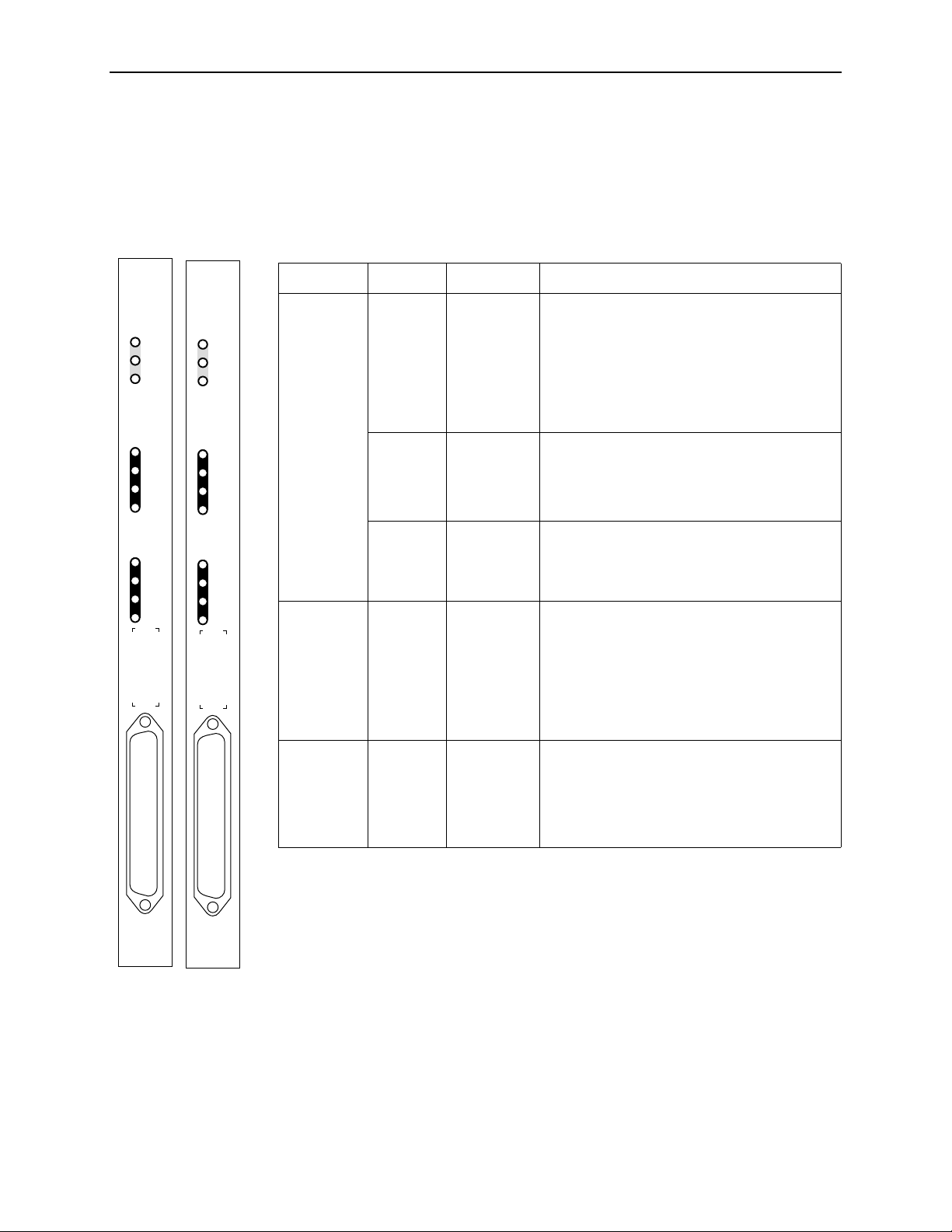
7. Monitoring and Troubleshooting
Front Panel L ED s
The following table descri bes the meaning and sta tes of the LEDs on the
faceplate. The LEDs for PORTS represent the DTE or DSL ports, depending upon
the Port LEDs selection on the Control screen (see
PORTS LEDs
Changing the Meaning of the
on page 7-25).
SYSTEM
OK
Alrm
Test
PORTS
1
2
3
4
5
6
7
8
SYSTEM
OK
Alrm
Test
PORTS
1
2
3
4
5
6
7
8
Type LED LED is . . .*
SYSTEM OK
(Green)
Alrm
(Amber)
Test
(Amber)
PORTS
1, 2, 3, 4,
5, 6, 7, 8
(when
DSX-1
(Green)
or
G.703
selected)
On
Off
Pulsing
Slow Cycling
On
Off
On
Off
Slow Cycling
On
Off
Slow Cycling
Fast Cyc ling
Indicating . . .
Unit failure; system processing functions have
stopped.
No power to card.
Normal operation; card functioning normally.
Unit is in minimum mode and a download is
required.
Device failure, Power-On Self- Test (POST) is
not complete, or an alarm was reported on a
DSL, DSX-1, or G.703 port.
No alarms.
Loopback test or 511 test pattern in progress.
No tests.
POST in progress.
Recover able signal present on the DSX-1 or
G.703 network.
No signal on the port.
Yellow Alarm Indication (DSX-1) or Remote
Alarm Indication (G.703).
An OOF, LOF, EER, or AIS condition exists.
PORTS
(when DSL
selected)
1, 2, 3, 4,
5, 6, 7, 8
(Green)
On
Off
Slow Cycling
Fast Cyc ling
DSL link is up.
DSL link is down.
DSL training in progress.
OOF condition.
* Slow Cycling: LED turns off and on in equal duration once per second.
Fast Cycling: LED turns off and on in equal duration 5 times per second.
Pulsing: LED turns off momentarily once per seco nd.
TDM
SDSL
8777
00-16604-01
7-24
May 2002 8700-A2-GB20-40
TDM
SDSL
8779
00-16605-01
Page 77
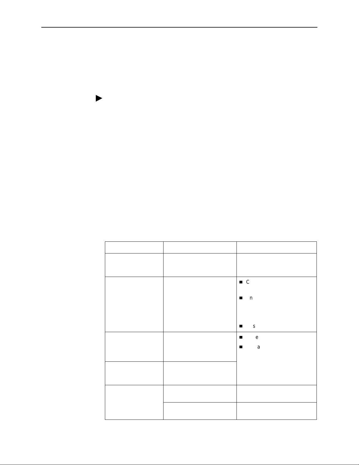
Changing the Meaning of the PORTS LEDs
The LEDs for PORTS on the front panel represent the status of the DSL network
or DTE ports, depending on the Port LEDs configuration option. The LED display
can also be selected at any time through the Control branch.
Procedure
To change the meaning of the LEDs for PORTS using the Control branch:
7. Monitoring and Troubleshooting
Troubleshooting
1. From the Main Menu, select Control
.
2. Move the cursor to the Port LEDs entr y.
3. Toggle the selection using the spacebar.
4. Press Enter.
The termination unit is designed to provide many years of trouble-free service. If a
problem occurs, however, refer to Table 7-6, Troubleshooting, for possible
solutions. If an error message is displayed under Health and Status on the System
and Test Status screen, refer to Table 7-1, Health and Status Messages, for the
recommended action.
Table 7-6. Troubleshooting (1 of 2)
Symptom Possible Cause Solutions
Alarm LED is on. A system failure has
occurred.
Cannot access t he unit
via the ATI.
The terminal is not set up for
the correct rate or data
format, or the unit is
configured so it prevents
access.
Refer to Tab l e 7-1, Health and
Status Messages, for
recommended action.
Check the cable and
connections.
Ensure that the unit i s
configured pro perl y in t he
DSLAM. Verify its IP
address.
Reset the unit.
Device F ail appears on
the System and Test
Status screen under
Self-Test results.
Power-On Self-Test
fails. Only Ala rm LED
is on after power-on.
No power, or the LEDs
are not lit.
8700-A2-GB20-40 May 2002
The unit detects an internal
hardware failure.
The unit has detected an
internal hardware failure.
The unit is not properly
seated in the DSLAM.
There is no power to the
DSLAM.
Reset the unit.
Contact your service
representative.
Verify that the unit is properly
inserted.
Verify that the DSLAM has
power.
7-25
Page 78
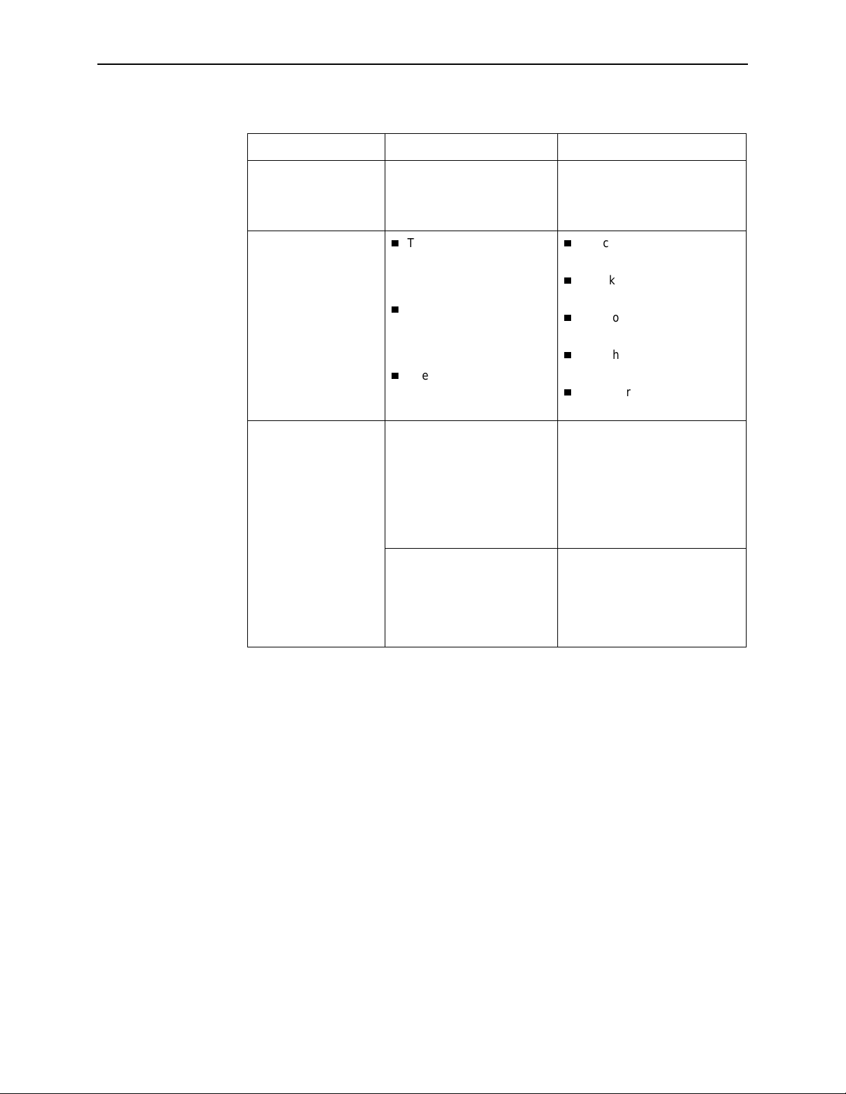
7. Monitoring and Troubleshooting
Table 7-6. Troubleshooting (2 of 2)
Symptom Possible Cause Solutions
An LED is not lit. LED is out. Run the Lamp Test. If the LED
in question does not flash with
the other LEDs, then contact
your service representative.
Not receiving data.
Not receiving data on
one or more time slots .
The network or DTE port
cables are not connected
(check front panel LEDs
for mo re informat ion).
A test is being executed
on the unit (check the
TEST LED on the front
panel).
The far-end device is
offline.
The DSL line rate does not
support the number of DSL
time slots defined.
The associated port is
administra tively disabl ed.
Check network and DTE p ort
cables.
Check Health and Status
menu.
Run Loopback tests . Refer to
Testing
Chapter8,
Stop the test or wait for the
.
test to end.
Make sur e the far-end de vi ce
is on.
Match the number of DSL time
slots to the DSL line ra te. See
Table A-2, Payload Rates and
DSL Line Rates f or Mode l 87 77,
Table A-3, Payload Rates and
DSL Line Rates for G.703, for
information about payload rates
for different DSL line rates.
Check the Display LEDs screen
to determine if the port is
disabled. Enable the port if
necessary using the Netw ork,
DSX-1, or G.703 Interface
Options screen.
7-26
May 2002 8700-A2-GB20-40
Page 79

Testing
Accessing the Test Menu
From the Test menu, you can run network tests, data port tests, and a front panel
lamp test .
To acc ess the Test menu, follow this menu selection sequence:
Main Menu→Test
main/test
Slot: 18 Model: 87xx
8
TEST
Network & DSX-1 | G.703 Tests
Device Tests
Abort All Tests
-------------------------------------------------------------------------------Ctrl-a to access these functions, ESC for previous menu MainMenu Exit
Select . . . To . . .
Network & DSX-1 Tests
Network & G.703 Tests
Device Tests Start and stop the Lamp Test.
Abort All Tests To abort current tests e xcluding network-initiated loopback
Start and stop tests on the DSX-1, G.703, or network
interface.
tests. An aborted test may continue to run for a few
seconds as the abort command is sent to the remote end
and processed.
8700-A2-GB20-40 May 2002
8-1
Page 80

8. Testing
Running Network Tests
Network tests require the participation of your network service provider. To access
the Network Tests screen, follow this menu selection sequence:
Main Menu→Test→Network & DSX-1 Tests
– or –
Main Menu
main/test/network_DSX1
Slot: 18 Model: 8777
Port: 1
NETWORK & DSX-1 TESTS
Test Command Status Results
-------------------------------------------------------------------------------Local Loopbacks
Network Line Loopback: Start Inactive 00:00:00
Network Repeater Loopback: Start Inactive 00:00:00
DSX-1 DTE Loopback: Start Inactive 00:00:00
Remote Loopbacks
Send Line Loopback: Down Send Inactive 00:00:00
Pattern Tests
Send and Monitor 511 Stop Active 10:12:42 - Errors 99999+
-------------------------------------------------------------------------------Ctrl-a to access these functions, ESC for previous menu MainMenu Exit
esetMon
R
main/test/network_G703
Slot: 4 Model: 8779
Port: 2
→
Test→Network & G.703 Tests
NETWORK & G.703 TESTS
Test Command Status Results
-------------------------------------------------------------------------------Local Loopbacks
Network Line Loopback: Start Inactive 00:00:00
Network Repeater Loopback: Start Inactive 00:00:00
G.703 DTE Loopback: Start Inactive 00:00:00
Network Remote Loopbacks
Send Line Loopback: Down
Network Pattern Tests
Send and Monitor 511 Stop Active 11:37:52 - Errors 99999+
-------------------------------------------------------------------------------Ctrl-a to access these functions, ESC for previous menu MainMenu Exit
R
esetMon
8-2
May 2002 8700-A2-GB20-40
Send Inactive 00:00:00
Page 81

8. Testing
Use the
Command
that a test is Inactiv e,
column to start or stop a test. When the
Start
is displayed; when a test is Active,
Status
Stop
column shows
is displayed.
Position the cursor at the desired Star t or Stop command and pres s Enter. The
Results
column displays the test duration.
Selecting Abort All Tests from the Test menu will not disrupt a Send and Monitor
511 test. When the Send and Monitor 511 test is active, R
esetMon is available to
reset the error counter to zero.
8700-A2-GB20-40 May 2002
8-3
Page 82
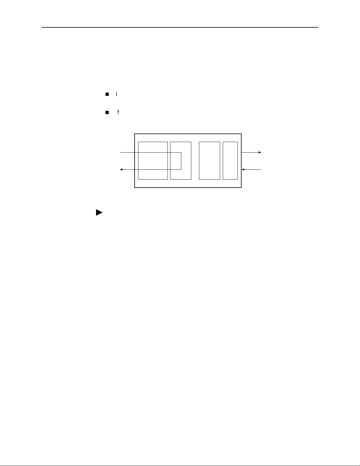
8. Testing
Network Line Loopback
A Network Line Loopback (LLB) loops the received signal on the network interface
back to the network without change.
For DSX-1 models:
If the DSL port is in a DS0 cross-connection, corresponding DSX-1 time slots
are sent all ones.
If the DSL port is in Bypass mode or a DS1 cross-connection, an AIS is sent to
the corresponding DSX-1 port.
CAP
DSL
Port
CAP T1/E1
FramerFramerTransceiver
LIU
AIS
DSX-1
or G.703
Port
02-16612-01
Procedure
To run a Network Line Loopback:
1. Position the cursor at the Star t comma nd next to Network Line Loopback on
the Network & DSX-1 or Network & G.703 Tests screen.
2. Press Enter.
The Start command is chan ged to Stop. Status is changed to Active.
3. To m anually stop the test, verify that the cursor is positioned at the Stop
command.
4. Press Enter.
Status is changed to Inactive.
The Network Line Loopback cannot be started when another loopback or pattern
test is in progress.
8-4
May 2002 8700-A2-GB20-40
Page 83
Repeater Loopback
8. Testing
A Repeater Loopback (RLB) loops the data normally sent to the DSL port back to
the connected DTE ports.
The DSL port is sent all ones and data received on the DSL link is ignored.
CAP
DSL
Port
AIS
CAP
T1/E1
Framer
or TSIFramerTransceiver
LIU
DSX-1
or G.703
Port
01-16613-01
Procedure
To run a Repeater Loopback:
1. Position the cursor at the Star t command next to Repeater Loopback on the
Network & DSX-1 or Network & G.703 Tests screen.
2. Press Enter.
The Start command is chan ged to Stop. Status is changed to Active.
3. To m anually stop the test, verify that the cursor is positioned at the Stop
command.
4. Press Enter.
Status is changed to Inactive.
A Repeater Loopback cannot be started when any other loopback test is in
progress.
8700-A2-GB20-40 May 2002
8-5
Page 84
8. Testing
DTE Loopback
DTE Loopback loops the DSX-1 or G.703 signal back to itself, retaining (bipolar
violation) BPV transparency. Also:
If the DSX-1 or G.703 port is in a DS0 cross-connection, the time slots
cross-connected to the DSX-1 or G.703 port are sent all ones.
If the DSX-1 or G.703 port is in Bypass mode or a DS1 cross-connection, all
ones are sent to the corresponding port and data received on the connected
por ts w ill b e ig nored.
CAP
DSL
All Ones
Port
CAP T1/E1
FramerFramerTransceiver
LIU
DSX-1
or G.703
Port
02-16614-01
Procedure
To ru n a DTE Loop back:
1. Position the cursor at the Star t command next to DTE Loopback on the
Network & DSX-1 or Network & G.703 Tests screen.
2. Press Enter.
The Start command is chan ged to Stop. Status is changed to Active.
3. To m anually stop the test, verify that the cursor is positioned at the Stop
command.
4. Press Enter.
Status is changed to Inactive.
The DTE Loopback cannot be started when any other loopback test is in progress.
8-6
May 2002 8700-A2-GB20-40
Page 85
Remote Send Line Loopback
The local unit initiates this test by sending a line loopback Up or Down command
to the remote unit for 10 second s. When the remote unit detects the loopback Up
command, it puts itself in line loopback and lights the front panel Test LED. The
remote unit remains in loopback until it receives a loopback Down command or the
remote unit’s test timeout value is exceeded. The Send Line Loopback tests both
units. External equipment can be used to verify the link.
Local Remote
8. Testing
CAPCAPT1/E1
LIU
Framer Framer Transceiver
CAP
CAP T1/E1
FramerFramerTransceiver
LIU
AIS
01-16615-01
DSX-1
or
G.703
Port
Procedure
To run a Remote Send Line Loopback:
1. Position the cursor at the Up or Down selection next to Send Line Loopback
on the Network & DSX-1 or Network & G.703 Tes ts screen.
2. Press the spacebar to select either Up or Down.
3. Position the cursor at the Send command next to Up or Down selection.
4. Press Enter.
The local unit stops sending the loopback command automatically after
10 seconds. Status is changed to Sending for 10 seconds, then back to
Inactive.
The Remote Send Line Loopback cannot be started when any other loopback or a
Send and Monitor 511 test is active on the network interface.
Remote Send Line Loopback cannot be used in cross-connect mode.
Procedure
To m anually stop a Remote Send Line Loopback:
1. Press the spacebar to select either Up or Down.
2. Position the cursor at the Send command next to Up or Down selection.
3. Press Enter.
8700-A2-GB20-40 May 2002
8-7
Page 86
8. Testing
Send and Monitor 511
T1/E1
LIU
AIS
Framer Framer Transceiver
The Send and Monitor 511 test causes the local and remote units to send a 511
test pattern to each other. The front panel Test LEDs of both units are on during
the test. The duration and results of the test are displayed on the Network Test
screen of the initiating unit. The card will send ones in the G.703 timeslots that are
mapped to the DSL port in test.
NOTE:
The Send and Monitor 511 test is not a loopback test. Each unit independently
sends and monitors a 511 pattern.
511
511
Gen
511
Mon
Pattern
511
Pattern
511
Mon
511
Gen
T1/E1
FramerFramerTransceiver
LIU
AIS
DSX-1
or G.703
Port
02-17209
Procedure
To run a Send and Monitor 511 test:
1. Position the cursor at the Start command next to Send and Monitor 511 on t he
Network & DSX-1 Tests screen or the Network & G.703 Test s screen.
2. Press Enter.
The Start command is changed to Stop.
3. To m anually stop the test, verify that the cursor is positioned at the Stop
command.
4. Press Enter.
When a Send and Monitor 511 test is active, a count of bit errors is displayed ne xt
to the test duration, and the R
Ty pe r or R or select the R
The Remote Send Line Loopback cannot be started when any other loopback or a
Send and Monitor 511 test is active on the Network interface.
esetMon virtual fun ction key is available for use.
esetMon virtual function key to reset the error count.
8-8
May 2002 8700-A2-GB20-40
Page 87

Device Tests
8. Testing
The Device Tests branch is only used to access the card-lev el test, the Lamp Test.
To acc ess the Device Tests screen, follow this menu selection sequence:
Main Menu→Test→Device Tests
main/test/card
Model: 87xx
DEVICE TESTS
Test Command Status
------------------------------------------------------------------------------- Lamp Test: Start Inactive
Lamp Test
-------------------------------------------------------------------------------Ctrl-a to access these functions, ESC for previous menu MainMenu Exit
The Lamp Test determines whether all LEDs are lighting and functioning properly.
Procedure
To test the LEDs:
1. Position the cursor at the Star t command next to Lamp Test on the Device
Tests screen.
2. Press Enter.
The Start command is changed to Stop. During the Lamp Test, all LEDs blink
simultaneously every second.
3. To stop the Lamp Test, position the cursor at the Stop command. The LEDs
are restored to their normal condition.
4. Press Enter.
8700-A2-GB20-40 May 2002
8-9
Page 88

8. Testing
Ending an Active Test
Except for the Remote Send Line Loopback, a test initiated by the user can be
ended by the user with the following methods:
T es t Ti me ou t op tio n
automatically terminate tests, and set the Test Duration (min) option to specify
the amount of time that tests can run before the unit terminates the test. The
default is 10 minutes. Refer to Table A- 7 , System O p tions, in Appendix A,
Configuration Options
Command column
position the cursor at Stop next to the active test and press Enter to stop a
specific test.
Abort All Tests menu selection
to stop all tests running on all interfaces.
when all tests on all interfaces have been term in ated. Network -initiated
loopbacks cannot be stopped from the Test menu.
An aborted test may continue to run for a few seconds as the Stop command is
sent to the remote end and processed.
– Enable the Test Timeout system option so the unit can
.
– Under the Command column on any test screen,
– Select Abort All Tests from the Test menu
Command Complete
appears
8-10
May 2002 8700-A2-GB20-40
Page 89
Telco-Initiated Tests
Hotwire 8777 Termination Units support Telco-initiated tests, as shown in the
following table.
8. Testing
Activation and
Deactivation
In-Band Signal Supported Not Applicabl e Not Supported
Bit-Oriented Supported Supported Supported
Message-Oriented Not Applicable Not Supported Not Applicable
Telco-Initiated L ine Loopback
Hotwire 8777 Termination Units support line loopback, as specified in AT&T
TR 54016, AT&T TR 62411, and ANS I T1.403. A Telco-Initiated Line Loopback
loops the received signal on the DSX-1 interface back to the DSX-1 interface
without modification. Framing, CRC, and FDL bits are returned unaltered, and no
BPVs or other line coding errors are removed. DSL time slots mapped to the
DSX-1 port are sent all ones.
DSL
All Ones
Port
Line
Loopback
CAP
Payload
Loopback
CAP T1
FramerFramerTransceiver
LIU
Remote Line
Loopback
DSX-1
Port
Telco
Telco-Initiated Payload Loopback
Hotwire 8777 Termination Units support payload loopback, as specified in AT&T
TR 54016 and ANSI T1 .403. A Telco-initiated line loopback loops the received
signal on the DSX-1 interface back to the DSX-1 interface . Framing, CRC, and
FDL bits are regenerated at the point of the loopback, and BPVs are removed.
DSL time slots mapped to the DSX-1 port are sent all ones.
DSL
All Ones
Port
CAP
CAP T1
FramerFramerTransceiver
LIU
99-16252
DSX-1
Port
99-16253
Telco
8700-A2-GB20-40 May 2002
8-11
Page 90
8. Testing
Telco-Initiated Remote Lin e Loopback
If Remote Tel co Loopback is enabled, a Telco-Initiated Line Loopback loops
received data at the remote unit and passes it back to the Telco through the local
unit.
The following figure shows the data flow for a remote Telco-initiated payload
loopback.
Local Remote
Telco
DSX-1
Port
CAPT1
LIU
Framer Framer Transceiver
Telco-Initiated Remote Line Loopback cannot be used in cross-connect mode.
CAP
DSL
CAP CAP T1
FramerFramerTransceiver
LIU
DSX-1
Port
AIS
99-16626
8-12
May 2002 8700-A2-GB20-40
Page 91

Transferring Firmware and Configurations Using TFTP
Downloading Firmware
The Download Code screen allows you to download firmware from a TFTP server
or MCP Flash File System (FFS). To acc ess the Download Code screen, follow
this menu selection sequence:
Main Menu→Control →Download Code
main/control/download_code
Slot: 4 Model: 87xx
9
DOWNLOAD CODE
Image File Name: Clear
TFTP Server IP Address: IP
Destination: DSL1
Immediately Apply Download: No
Start Transfer: Yes
Packets Sent: 0000000
Packets Received: 0000000
Bytes Sent: 0000000
Bytes Received: 0000000
Transfer Status: Transfer Pending
------------------------------------------------------------------------------Ctrl-a to access these functions, ESC for previous menu MainMenu Exit
000.000.000.000 Clear
8700-A2-GB20-40 May 2002
9-1
Page 92

9. Transferring Firmware and Configurations Using TFTP
Procedure
To download firm ware:
1. Position the cursor in the Image File Name field. Type the name of the file to
be downloaded.
The file name must be a regular path name expression of directory names
separated by a forward slash (/) ending with the file name. The total path
name length can be up to 128 characters.
2. Position the cursor in the TFTP Server IP Address field. Enter the TFTP server
IP address or M1 for the MCP FFS.
The first three digits of the IP address cannot be 000 or greater than 223.
3. For an LTU, go to Step 4 . For an NTU, position the cursor in the Destination
field. Use the spacebar to select a network destination for the TFTP server .
4. Position the cursor in the Immediately Apply Download field. If you would like
the download to be effective immediately, select
Yes
.
5. Position the cursor at the Start Transfer field. Use the spacebar to select
Press Enter.
When the data transfer is complete:
— If you selected Yes in Step 4, the card is reset.
— If you selected No, the Transfer Status field changes to
successfully
.
Completed
If you specified No (the default) in the Immediately Apply Download field in
Step 4, you must now apply the download.
main/control/apply_download
Model: 87xx
APPLY DOWNLOAD
Switch To Code Revision A01.00.02: No
WARNING:
An answer of “yes” will cause the system
to reset as if it had been powered off and on!
Yes
.
------------------------------------------------------------------------------Ctrl-a to access these functions, ESC for previous menu M
Select: Yes, No LOS at Net, Pt 1
9-2
May 2002 8700-A2-GB20-40
ainMenu Exit
Page 93

9. Transferring Firmware and Configurations Using TFTP
Procedure
To appl y the downloaded fir mware:
1. Press the Escape key to return to the Control menu. Select Apply Download.
2. On the Apply Download screen, type
code.
Selecting Yes causes the ter mi nation unit to reset.
to reset the card and activate the
Yes
NOTE:
The termination unit has two flash memory banks to hold executable firmware.
You can switch between these two firmware versions by appl ying the firmware
listed on the Apply Download screen.
8700-A2-GB20-40 May 2002
9-3
Page 94

9. Transferring Firmware and Configurations Using TFTP
Configuration Loader
The Configuration Loader screen allows you to upload configurations to and
download configurations from a TFTP server or the MCP FFS. T o access the
Configuration Loader screen, follow this menu selection sequenc e:
Main Menu→Configuration →Configuration Loader
main/config/config_loader
Slot: 4 Model: 87xx
CONFIGURATION LOADER
Image File Name:
TFTP Server IP Address: IP
TFTP Transfer Direction: Download from Server
Destination: DSL1
Start Transfer: Yes
Packets Sent: 0000000
Packets Received: 0000000
Bytes Sent: 0000000
Bytes Received: 0000000
Transfer Status: Transfer Pending
Activate new configuration? No
------------------------------------------------------------------------------Ctrl-a to access these functions, ESC for previous menu M
000.000.000.000 Clear
Clear
ainMenu Exit
Procedure
To upload or download a configuration:
1. Position the cursor in the Image File Name field. Type the name of the file to
be downloaded, or the name to be used for the file to be uploaded.
The file name may be a regular path name expression of director y names
separated by a forward slash (/) ending with the file name. The total path
name length can be up to 128 characters.
—
DOS machine:
If the TFTP server is hosted by a DOS machine, then
directory and filenames must consist of eight or less characters with an
optional suffix of up to three characters. The system will automatically
upload the configuration file and create directories and filenames as
needed.
—
UNIX machine:
If your server is hosted by a UNIX machine, the
configuration file you name must already exist. It will not be created on the
UNIX system by the TFTP server. It is critical that you work with your
system administrator to plan the naming conventions for directories,
filenames, and permissions so that anyone using the system has read and
write permissions.
—
MCP FFS:
When uploading configuration files to the MCP FFS, the
directory and filename must be entered, otherwise the download will fail.
9-4
May 2002 8700-A2-GB20-40
Page 95

9. Transferring Firmware and Configurations Using TFTP
2. Position the cursor in the TFTP Server IP Address field. Enter the TFTP server
IP address or M1 for the MCP F FS.
The first three digits of the IP address cannot be 000 or greater than 223.
3. Position the cursor in the TFTP Transf er Dir ection field. Use the spacebar to
select Download from Server or Upload to Server .
4. For an LTU, go to Step 5 . For an NTU, position the cursor in the Destination
field. Use the spacebar to select a network destination for the TFTP server .
Select DSL if the TFTP server destination is the DSL link port or IMC (Internal
Management Channel) if the TFTP destination is the Management port of the
MCC card.
5. Position the cursor at the Start Transfer field. Use the spacebar to select Yes.
Press Enter.
When the data transfer is complete, the Transfer Status field changes to
Completed successfully
.
6. Position the cursor at the
select
to activate a new downloaded configuration. Press Enter.
Yes
Activate new configuration?
prompt and
NOTE:
The following options are not changed:
— DSL Mode and Telnet Session configuration options
— Peer IP address
You must change these settings with the appropr iate confi guration menus
after the new configuration is activated. See Table A -7, Syst e m Optio n s , and
Table A-12, Telnet Session Options, in Appendix A,
Configuration Options
.
8700-A2-GB20-40 May 2002
9-5
Page 96

9. Transferring Firmware and Configurations Using TFTP
9-6
May 2002 8700-A2-GB20-40
Page 97

Configuration Options
Overview
The tables in this appendix summarize the configuration options accessed when
you select Currrent Configuration on the Main Menu. The configuration options are
arranged into groups based upon functionality.
Select . . . To Access the . . . To Configure the . . .
Network Network Interface Options (Table A-1) DSL interface ports.
A
DSX-1
G.703
Copy P orts Copy Port Options (Table A-6) DSL network and DTE
System Options System Options (Table A-7) General system options of
System Clock System Clock Options (Table A-8) System clock options.
Cross-Connect Cross-Connect Mode Options –
Management
and
Communication
DSX-1 Interface Options – Model 8777
(Table A-4)
G.703 Interf ace Options – Model 8779
(Table A-5)
Model 8777 (Table A-9)
Cross-Connect Mode Opti ons –
Model 8779 (Table A-10)
Assign Time Slots Options (Table A-11)
Telnet Session Options (Table A-12)
General SNMP Management
Options (Table A-13)
SNMP NMS Security Options
(Table A-14)
SNMP Traps Options (Table A-15)
Inband Management Channel
Options – Model 8779 (Table A-16)
DSX-1 interface ports
(Model 8777).
G.703 interface ports
(Model 8779).
inter fa ce por ts by copying
options from port to port.
the unit.
DS1 and DS0 cross- con nect
ports.
Management support of the
unit through SNMP, Telnet,
and the Inband
Management Channel.
8700-A2-GB20-40 May 2002
A-1
Page 98

A. Configuration Options
NOTE:
All changes to configuration options must be saved. Refer to
Configuration Options
Network Interface Options Menu
For Network Interface Options, refer to Table A-1, Network Interface Options. To
access the Network Interface Options screen, follow this menu selection
sequence:
Main Menu→Configuration→Current Configuration→Network
main/config/network
Slot: 18 Model: 87xx
Port 2
NETWORK INTERFACE OPTIONS
Port Status Enable
Margin Threshold: 0db
Excessive Error Rate Threshold: 1E–6
AutoRate: Disable
DSL Line Rate: 1552 Kbps
EIA-530 Payload Rate 1536
Transmit Attenuation 0dB
Peer IP Address: 111.255.255.000 Clear
DS0 Cross Connect Line Framing: ESF
in Chapter 3,
Saving
Initial Startup and Configuration
Kbps
.
Circuit Identifier: Clear
-------------------------------------------------------------------------------Ctrl-a to access these functions, ESC for previous menu M
ave
S
ainMenu Exit
Table A-1. Networ k Inte rfac e Opt ion s (1 of 4)
Port Status
Possible Settings: Enable, Disable
Default Setti ng: Enable
Determines whether the port can be configured and used.
Enable – The port can be configured and used.
Disable – The port cannot be configured or used.
Margin Threshold
Possible Settings: –5db, –4db, –3db, –2db, –1db, 0db, 1db, 2db, 3db, 4db, 5db,
6db, 7db, 8db, 9db, 10d b
Default Setti ng: 0db
Determines the le vel , e xpr essed in de cibel s, at whic h a signal -to- noise mar gin condi tion is
recognized.
–5db to 10db – Sets the margin threshold to this value.
A-2
May 2002 8700-A2-GB20-40
Page 99
A. Configuration Opt ions
Table A-1. Networ k Inte rfac e Opt ion s (2 of 4)
Excessive Error Rate Threshold
Possible Settings: 1E–4, 1E–5, 1E– 6, 1E–7, 1E–8, 1E–9
Default Setti ng: 1E– 6
Determines the error rate at which an excessive err or rate (EER) condition is recogni zed.
The rate is the ratio of the number of CRC errors to the number of bits rece ived in a
certain period.
1E–4 – 1E-9 – The rate at which EER is recognized.
AutoRate
Possible Settings: Enable, Disable
Default Setti ng: Disable
Determines whether the unit automatically adjusts to the best line rate for conditions , or is
fixed at the rate in the DSL Line Rate fi eld. The automatically set rate cannot exceed Max
DSL AutoRate.
AutoRate is only available when t he unit is configured as an LTU.
Enable – The LTU adjusts to the best line rate.
Disable – The LTU’s l ine rate is the DSL Line Rate selected.
DSL Line Rate
Possi ble Settings (Model 8777): 144, 272, 400, 528, 784, 1040, 1552
Default Setti ng: 1552
Possi ble Settings (Model 8779): 144, 272, 400, 528, 784, 1040, 1552, 2064
Default Setti ng: 2064
Specifies the fi xed l ine r ate of t he LTU when AutoRate is disabl ed. See Table A-2, P a yload
Rates and DSL Line Rates for Model 8777, or Table A-3, Payload Rates and DSL Line
Rates for G.703, for information about maximum payload rates for different DSL line rate.
DSL Line Rate is only available when the uni t is c onfigu red as an LTU and AutoRate
is disabled.
144 – 2064 – The fixed DSL Line Rate, in Kbps.
Max DSL AutoRate
Possi ble Settings (Model 8777): 144, 272, 400, 528, 784, 1040, 1552
Default Setti ng: 1552
Possi ble Settings (Model 8779): 144, 272, 400, 528, 784, 1040, 1552, 2064
Default Setti ng: 2064
Specifies the maximum rate to which the unit can AutoRate. See Table A-2, Payload
Rates and DSL Line Rates for Model 8777, or Table A-3, Payload Rates and DSL Line
Rates for G. 703, for inf ormation about maximum pa yload rates for differen t DSL l ine rates.
Max DSL AutoRate is only available when the unit is configured as an LTU and
AutoRate is enabled.
144 – 2064 – The AutoRate ceiling, in Kbps.
8700-A2-GB20-40 May 2002
A-3
Page 100
A. Configuration Options
Table A-1. Networ k Inte rfac e Opt ion s (3 of 4)
EIA-530 Payload Rate
Possi ble Settings (Model 8777): 64, 128, 256, 384, 512, 768, 1024, 1536
Default Setti ng: 1536
Possi ble Settings (Model 8779): 64, 128, 192, 256, 320, 384, 448, 512, 576, 640, 768,
960, 1024, 1536, 1920, 1984, 2048
Default Setti ng: 2048
Specifies the synchronous port speed of a remote NTU that is an EIA-530 model so the
unit can run at the highest DSL line r ate supported.
EIA-530 Payload Rate is only av ailable when the unit is configu red as an LTU.
For the Model 8779 to achieve the payload rates listed abo ve, both the 8779 card
and the 7975-A2 endpoint mu st be operating with firmware 02.03.12 or greater. In
lower firmware versions, the payload rate is only selectable at a DSL line rate of
144 Kbps while all other ra tes default to the maximum, depending on the DSL line
rate selected.
64 – 2048 – The synchronous port speed of the remote NTU, in Kbps.
T ransmit Attenuation
Possible Settings: 0dB – 15dB
Default Setti ng: 0dB
Determines how much the unit’s transmit power is reduced to accommodate a short line
length.
0dB – The full transmit power is used (no attenuation).
1dB – 15dB – The unit’s transmit power is reduced by the specified amount.
Peer IP Addres s
(LTU)
Possible Settings: 001.000.000.000 – 223.255.255.255, Clear
Default Setti ng: 000.000.000.000
Specifies the peer IP addr ess providing the remote management link on the DSL loop.
Peer IP Address is onl y available when the unit is configured as an LTU and the unit
is in not running in IP Conservative mode.
Address Field – (001.000.000.000 – 223.255.255.255) – Enter an address for the peer
unit. The range for the fi rst byte is 0 01 to 223, with the exception of 127. The range for the
remaining three b ytes is 000 to 255. The IP address must be in the same subnet as the
MCC backplane address.
Clear – Clears the IP address and sets to all zeros.
A-4
May 2002 8700-A2-GB20-40
 Loading...