

Page 1

HOTWIREr 8540 AND
8546 RADSL CARDS
USER’S GUIDE
Document No. 8000-A2-GB20-50
April 2000
Page 2

Copyright E 2000 Paradyne Corporation.
All rights reserved.
Printed in U.S.A.
Notice
This publication is protected by federal copyright law. No part of this publication may be copied or distributed,
transmitted, transcribed, stored in a retrieval system, or translated into any human or computer language in any form
or by any means, electronic, mechanical, magnetic, manual or otherwise, or disclosed to third parties without the
express written permission of Paradyne Corporation, 8545 126th Avenue North, P.O. Box 2826, Largo,
Florida 33779-2826.
Paradyne Corporation makes no representation or warranties with respect to the contents hereof and specifically
disclaims any implied warranties of merchantability or fitness for a particular purpose. Further, Paradyne Corporation
reserves the right to revise this publication and to make changes from time to time in the contents hereof without
obligation of Paradyne Corporation to notify any person of such revision or changes.
Changes and enhancements to the product and to the information herein will be documented and issued as a new
release to this manual.
Warranty, Sales, Service, and Training Information
Contact your local sales representative, service representative, or distributor directly for any help needed. For
additional information concerning warranty , sales, service, repair, installation, documentation, training, distributor
locations, or Paradyne worldwide office locations, use one of the following methods:
H Internet: Visit the Paradyne World Wide Web site at www.paradyne.com. (Be sure to register your warranty
there. Select Service & Support → Warranty Registration.)
H Telephone: Call our automated system to receive current information by fax or to speak with a company
representative.
— Within the U.S.A., call 1-800-870-2221
— Outside the U.S.A., call 1-727-530-2340
Trademarks
ACCULINK, COMSPHERE, FrameSaver, Hotwire, and NextEDGE are registered trademarks of Paradyne
Corporation. MVL, OpenLane, Performance Wizard, and TruePut are trademarks of Paradyne Corporation. All other
products and services mentioned herein are the trademarks, service marks, registered trademarks, or registered
service marks of their respective owners.
Document Feedback
We welcome your comments and suggestions about this document. Please mail them to Technical Publications,
Paradyne Corporation, 8545 126th Ave. N., Largo, FL 33773, or send e-mail to userdoc@paradyne.com. Include
the number and title of this document in your correspondence. Please include your name and phone number if you
are willing to provide additional clarification.
Printed on recycled paper
A
April 2000
8000-A2-GB20-50
Page 3

Contents
About This Guide
H Document Purpose and Intended Audience v. . . . . . . . . . . . . . . . . . . . . . . . .
H Document Summary vi. . . . . . . . . . . . . . . . . . . . . . . . . . . . . . . . . . . . . . . . . . . . .
H Product-Related Documents vi. . . . . . . . . . . . . . . . . . . . . . . . . . . . . . . . . . . . . .
1 Hotwire DSL System Description
H What is the Hotwire DSL System? 1-1. . . . . . . . . . . . . . . . . . . . . . . . . . . . . . . . .
Hotwire DSL Chassis 1-3. . . . . . . . . . . . . . . . . . . . . . . . . . . . . . . . . . . . . . . .
MCC Card 1-6. . . . . . . . . . . . . . . . . . . . . . . . . . . . . . . . . . . . . . . . . . . . . . . . . .
RADSL Cards 1-6. . . . . . . . . . . . . . . . . . . . . . . . . . . . . . . . . . . . . . . . . . . . . . .
H Features 1-7. . . . . . . . . . . . . . . . . . . . . . . . . . . . . . . . . . . . . . . . . . . . . . . . . . . . . . .
H Levels of Access 1-7. . . . . . . . . . . . . . . . . . . . . . . . . . . . . . . . . . . . . . . . . . . . . . . .
H Software Functionality 1-7. . . . . . . . . . . . . . . . . . . . . . . . . . . . . . . . . . . . . . . . . . .
Configuring the DSL Cards 1-8. . . . . . . . . . . . . . . . . . . . . . . . . . . . . . . . . . .
Monitoring the DSL Cards 1-8. . . . . . . . . . . . . . . . . . . . . . . . . . . . . . . . . . . .
Troubleshooting and Diagnostics 1-9. . . . . . . . . . . . . . . . . . . . . . . . . . . . . .
2 Hotwire Menus and Screens
H Menu and Screen Formats 2-1. . . . . . . . . . . . . . . . . . . . . . . . . . . . . . . . . . . . . . .
Components of a Hotwire Menu 2-2. . . . . . . . . . . . . . . . . . . . . . . . . . . . . . .
Components of a Hotwire Screen 2-3. . . . . . . . . . . . . . . . . . . . . . . . . . . . . .
H Commonly Used Navigation Keys 2-4. . . . . . . . . . . . . . . . . . . . . . . . . . . . . . . . .
H Levels of Access 2-5. . . . . . . . . . . . . . . . . . . . . . . . . . . . . . . . . . . . . . . . . . . . . . . .
H User Login Screen 2-6. . . . . . . . . . . . . . . . . . . . . . . . . . . . . . . . . . . . . . . . . . . . . .
H Hotwire Menu Hierarchy 2-7. . . . . . . . . . . . . . . . . . . . . . . . . . . . . . . . . . . . . . . . .
Hotwire Chassis Main Menu 2-7. . . . . . . . . . . . . . . . . . . . . . . . . . . . . . . . . .
Hotwire – DSL Menu 2-8. . . . . . . . . . . . . . . . . . . . . . . . . . . . . . . . . . . . . . . . .
DSL Card Configuration Menu 2-9. . . . . . . . . . . . . . . . . . . . . . . . . . . . . . . .
DSL Card Monitoring Menu 2-10. . . . . . . . . . . . . . . . . . . . . . . . . . . . . . . . . . .
H Logging In to the System 2-10. . . . . . . . . . . . . . . . . . . . . . . . . . . . . . . . . . . . . . . . .
Card Selection Screen 2-11. . . . . . . . . . . . . . . . . . . . . . . . . . . . . . . . . . . . . . .
Accessing the Hotwire – DSL Menu 2-13. . . . . . . . . . . . . . . . . . . . . . . . . . . .
H Exiting From the System 2-13. . . . . . . . . . . . . . . . . . . . . . . . . . . . . . . . . . . . . . . . .
Manually Logging Out 2-13. . . . . . . . . . . . . . . . . . . . . . . . . . . . . . . . . . . . . . . .
Automatically Logging Out 2-13. . . . . . . . . . . . . . . . . . . . . . . . . . . . . . . . . . . .
8000-A2-GB20-50
April 2000
i
Page 4

Contents
3 RADSL Card Configuration
H Overview 3-1. . . . . . . . . . . . . . . . . . . . . . . . . . . . . . . . . . . . . . . . . . . . . . . . . . . . . .
H Port Naming Conventions 3-1. . . . . . . . . . . . . . . . . . . . . . . . . . . . . . . . . . . . . . . .
H Configuring the MCC Card, DSL Cards, and RTUs 3-2. . . . . . . . . . . . . . . . . .
H DSL Configuration Card Status Screens 3-7. . . . . . . . . . . . . . . . . . . . . . . . . . .
H DSL Configuration Ports Screens 3-12. . . . . . . . . . . . . . . . . . . . . . . . . . . . . . . . .
H DSL Configuration Interfaces Screens 3-15. . . . . . . . . . . . . . . . . . . . . . . . . . . . .
H DSL Configuration Users Screens 3-18. . . . . . . . . . . . . . . . . . . . . . . . . . . . . . . . .
H DSL Configuration IP Router Screens 3-20. . . . . . . . . . . . . . . . . . . . . . . . . . . . . .
H DSL Configuration SNMP Screens 3-26. . . . . . . . . . . . . . . . . . . . . . . . . . . . . . . .
Management System Source Validation for RADSL Cards 3-26. . . . . . . .
H DSL Configuration DHCP Relay Screens 3-28. . . . . . . . . . . . . . . . . . . . . . . . . . .
Configuring DHCP Relay Agent (dynamic addressing) 3-29. . . . . . . . . . . .
H DSL Configuration RTU Screens 3-31. . . . . . . . . . . . . . . . . . . . . . . . . . . . . . . . . .
4 Monitoring the Hotwire DSL System
H Overview 4-1. . . . . . . . . . . . . . . . . . . . . . . . . . . . . . . . . . . . . . . . . . . . . . . . . . . . . .
H DSL Monitoring Menu 4-1. . . . . . . . . . . . . . . . . . . . . . . . . . . . . . . . . . . . . . . . . . .
H DSL Monitoring Card Status Screens 4-2. . . . . . . . . . . . . . . . . . . . . . . . . . . . . .
H DSL Monitoring Physical Layer Screens 4-4. . . . . . . . . . . . . . . . . . . . . . . . . . . .
H DSL Monitoring Interfaces Screens 4-10. . . . . . . . . . . . . . . . . . . . . . . . . . . . . . . .
H DSL Network Protocol Screens 4-12. . . . . . . . . . . . . . . . . . . . . . . . . . . . . . . . . . .
H DSL IP Router Screens 4-20. . . . . . . . . . . . . . . . . . . . . . . . . . . . . . . . . . . . . . . . . .
H DSL Configuration RTU Screens 4-23. . . . . . . . . . . . . . . . . . . . . . . . . . . . . . . . . .
5 Diagnostics and Troubleshooting
H Overview 5-1. . . . . . . . . . . . . . . . . . . . . . . . . . . . . . . . . . . . . . . . . . . . . . . . . . . . . .
H Applications Screens 5-1. . . . . . . . . . . . . . . . . . . . . . . . . . . . . . . . . . . . . . . . . . . .
H Diagnostic Screens 5-3. . . . . . . . . . . . . . . . . . . . . . . . . . . . . . . . . . . . . . . . . . . . . .
H Troubleshooting 5-5. . . . . . . . . . . . . . . . . . . . . . . . . . . . . . . . . . . . . . . . . . . . . . . . .
Checking Alarms 5-5. . . . . . . . . . . . . . . . . . . . . . . . . . . . . . . . . . . . . . . . . . . .
No Response at Startup 5-5. . . . . . . . . . . . . . . . . . . . . . . . . . . . . . . . . . . . . .
Major Alarms 5-5. . . . . . . . . . . . . . . . . . . . . . . . . . . . . . . . . . . . . . . . . . . . . . .
Minor Alarms 5-7. . . . . . . . . . . . . . . . . . . . . . . . . . . . . . . . . . . . . . . . . . . . . . .
H SYSLOG Messages 5-9. . . . . . . . . . . . . . . . . . . . . . . . . . . . . . . . . . . . . . . . . . . . .
Example SYSLOG Messages 5-9. . . . . . . . . . . . . . . . . . . . . . . . . . . . . . . . .
H Network Problems 5-1 1. . . . . . . . . . . . . . . . . . . . . . . . . . . . . . . . . . . . . . . . . . . . . .
ii
April 2000
8000-A2-GB20-50
Page 5

A Download Code
H Download Code A-2. . . . . . . . . . . . . . . . . . . . . . . . . . . . . . . . . . . . . . . . . . . . . . . . .
H Apply Download A-2. . . . . . . . . . . . . . . . . . . . . . . . . . . . . . . . . . . . . . . . . . . . . . . .
B SNMP Traps
H Setting Up SNMP Trap Features B-1. . . . . . . . . . . . . . . . . . . . . . . . . . . . . . . . . .
H DSL Card Traps B-3. . . . . . . . . . . . . . . . . . . . . . . . . . . . . . . . . . . . . . . . . . . . . . . .
H RTU Related Traps B-7. . . . . . . . . . . . . . . . . . . . . . . . . . . . . . . . . . . . . . . . . . . . . .
Contents
Fully Operational System A-2. . . . . . . . . . . . . . . . . . . . . . . . . . . . . . . . . . . . .
Scenario Two: Download Only System A-2. . . . . . . . . . . . . . . . . . . . . . . . .
DSL SNMP Community Strings and Authentication Failure Trap B-1. . .
Enable DSL Port Traps B-2. . . . . . . . . . . . . . . . . . . . . . . . . . . . . . . . . . . . . . .
Standard Traps B-7. . . . . . . . . . . . . . . . . . . . . . . . . . . . . . . . . . . . . . . . . . . . .
Enterprise-Specific Traps B-7. . . . . . . . . . . . . . . . . . . . . . . . . . . . . . . . . . . . .
C 5446 RTU Setup
H Hotwire 5446 RTU Setup Overview C-1. . . . . . . . . . . . . . . . . . . . . . . . . . . . . . . .
H Accessing the Hotwire 5446 RTU IP Injection MIB C-3. . . . . . . . . . . . . . . . . . .
H Viewable 5446 RTU ARP Table C-12. . . . . . . . . . . . . . . . . . . . . . . . . . . . . . . . . . .
Glossary
Index
Downloading the IP Injection Tool C-3. . . . . . . . . . . . . . . . . . . . . . . . . . . . . .
Accessing the IP Injection Tool C-4. . . . . . . . . . . . . . . . . . . . . . . . . . . . . . . .
Community String Entries C-5. . . . . . . . . . . . . . . . . . . . . . . . . . . . . . . . . . . . .
IP and Device MIBs Supported C-6. . . . . . . . . . . . . . . . . . . . . . . . . . . . . . . .
Additional pdn-common MIBs Supported C-6. . . . . . . . . . . . . . . . . . . . . . .
Configuration Requirements C-7. . . . . . . . . . . . . . . . . . . . . . . . . . . . . . . . . .
Network Management Systems C-8. . . . . . . . . . . . . . . . . . . . . . . . . . . . . . .
Using a MIB Browser C-9. . . . . . . . . . . . . . . . . . . . . . . . . . . . . . . . . . . . . . . .
MIB Browser Techniques C-10. . . . . . . . . . . . . . . . . . . . . . . . . . . . . . . . . . . . .
IP Injection Tool Group Objects Table C-11. . . . . . . . . . . . . . . . . . . . . . . . . .
8000-A2-GB20-50
April 2000
iii
Page 6

Contents
This page intentionally left blank.
iv
April 2000
8000-A2-GB20-50
Page 7

About This Guide
Document Purpose and Intended Audience
This guide describes how to configure and operate the software component of
the Hotwire Digital Subscriber Line Access Multiplexer (DSLAM) system.
Specifically, this document addresses the use of the following cards in the
DSLAM:
H 8540 Rate Adaptive Digital Subscriber Line (RADSL) card.
H 8546 Rate Adaptive Digital Subscriber Line (RADSL) card.
This document is intended for administrators and operators who maintain the
networks that support Hotwire operation. A basic understanding of
internetworking protocols and their features is assumed. Specifically, you should
have familiarity with Simple Network Management Protocol (SNMP), Network
Management Systems (NMSs), and the following internetworking concepts:
H TCP/IP applications
H IP and subnet addressing
H IP forwarding (also referred to as IP routing)
It is also assumed that you have already installed either the Hotwire 8600/8610,
8800/8810 DSLAM, or 8820 GranDSLAM. If you have not done so already, refer
to the appropriate Hotwire DSLAM or GranDSLAM installation document for
installation instructions.
NOTE:
It is highly recommended that you read the Hotwire DSLAM for 8540 and
8546 DSL Cards Network Configuration Guide before you begin to use this
guide and the Hotwire software. The Network Configuration Guide provides
introductory information about the Hotwire DSLAM network model and
theories. It is also recommended that you read the Hotwire Management
Communications Controller (MCC) Card User’s Guide.
8000-A2-GB20-50
April 2000
v
Page 8

About This Guide
Document Summary
Section Description
Chapter 1 Hotwire DSL System Description. Provides an
Chapter 2 Hotwire Menus and Screens. Describes the operation
Chapter 3 RADSL Card Configuration. Describes the optional
Chapter 4 Monitoring the Hotwire DSL System. Describes
Chapter 5 Diagnostics and Troubleshooting. Describes common
overview of the Hotwire DSLAM and GranDSLAM
systems.
of Hotwire menus, screens, and commonly used
navigation keys. Also provides instructions on how to
log in and log out of the system.
procedures for configuring the DSL cards on the
Hotwire system.
operator programs that monitor the Hotwire system.
Hotwire operational problems and solutions.
Appendix A Download Code. Describes how to work with the
Appendix B SNMP T raps. Describes the traps that are generated
Appendix C 5446 RTU Setup. Describes MIB details including the
Glossary Defines acronyms and terms used in this document.
Index Lists key terms, acronyms, concepts, and sections in
Product-Related Documents
Document Number Document Title
5020-A2-GN10 Hotwire POTS Splitter Central Office Installation
5030-A2-GN10 Hotwire 5030 POTS Splitter Customer Premises
5038-A2-GN10 Hotwire 5038 Distributed POTS Splitter Installation
Download Code and Apply Download menus.
by the Hotwire system.
Injection MIB and other enterprise MIBs.
alphabetical order.
Instructions
Installation Instructions
Instructions
vi
5216-A2-GN10 Hotwire 5216 RTU Customer Premises Installation
Instructions
5246-A2-GN10 Hotwire 5246 RTU Customer Premises Installation
Instructions
5446-A2-GN10 Hotwire 5446 RTU Customer Premises Installation
Instructions
April 2000
8000-A2-GB20-50
Page 9

About This Guide
Document Number Document Title
7700-A2-GB23 OpenLane DCE Manager for HP OpenView for
Windows User’s Guide
7800-A2-GB26 OpenLane DCE Manager User’s Guide
7800-A2-GB28 OpenLane Performance Wizard User’s Guide
8000-A2-GB21 Hotwire 8540 and 8546 RADSL Cards Network
Configuration Guide
8000-A2-GB25 Hotwire 8100/8200 Interworking Packet Concentrator
(IPC) Network Configuration Guide
8000-A2-GB29 Hotwire Management Communications Controller
(MCC) Card User’s Guide
8000-A2-GB90 Hotwire 8100/8200 Internetworking Packet
Concentrator (IPC) User’s Guide
(Feature No. 8200-M2-901)
8000-A2-GN11 Hotwire Management Communications Controller
(MCC) Card Installation Instructions
8540-A2-GN10 Hotwire 8540 RADSL Card Installations Instructions
8546-A2-GN10 Hotwire 8546 RADSL Card Installation Instructions
8600-A2-GN20 Hotwire 8600 Digital Subscriber Line Access
Multiplexer (DSLAM) Installation Guide
8610-A2-GN10 Hotwire 8610 DSLAM Installation Instructions
8800-A2-GN21 Hotwire 8800 Digital Subscriber Line Access
Multiplexer (DSLAM) Installation Guide
8810-A2-GN11 Hotwire 8810 DSLAM Installation Instructions
8820-A2-GN20 Hotwire 8820 GranDSLAM Installation Guide
Contact your sales or service representative to order additional product
documentation.
Paradyne documents are also available on the World Wide Web at
www.paradyne.com. Select Library → Technical Manuals
8000-A2-GB20-50
April 2000
vii
Page 10

About This Guide
This page intentionally left blank.
viii
April 2000
8000-A2-GB20-50
Page 11

Hotwire DSL System Description
What is the Hotwire DSL System?
The Hotwirer Digital Subscriber Line (DSL) system is a set of central site
products that terminate and consolidate packet data traffic from many customers
in a serving area. The DSL card(s) then forwards the traffic to one or more
network access provider networks.
High-speed Internet and intranet access is bridged on the DSL port cards and
multiplexed over backbone networks. By enabling very high speeds using DSL
technology and concentrating Internet Protocol (IP) traffic, greater performance is
realized.
1
8000-A2-GB20-50
April 2000
1-1
Page 12
Hotwire DSL System Description
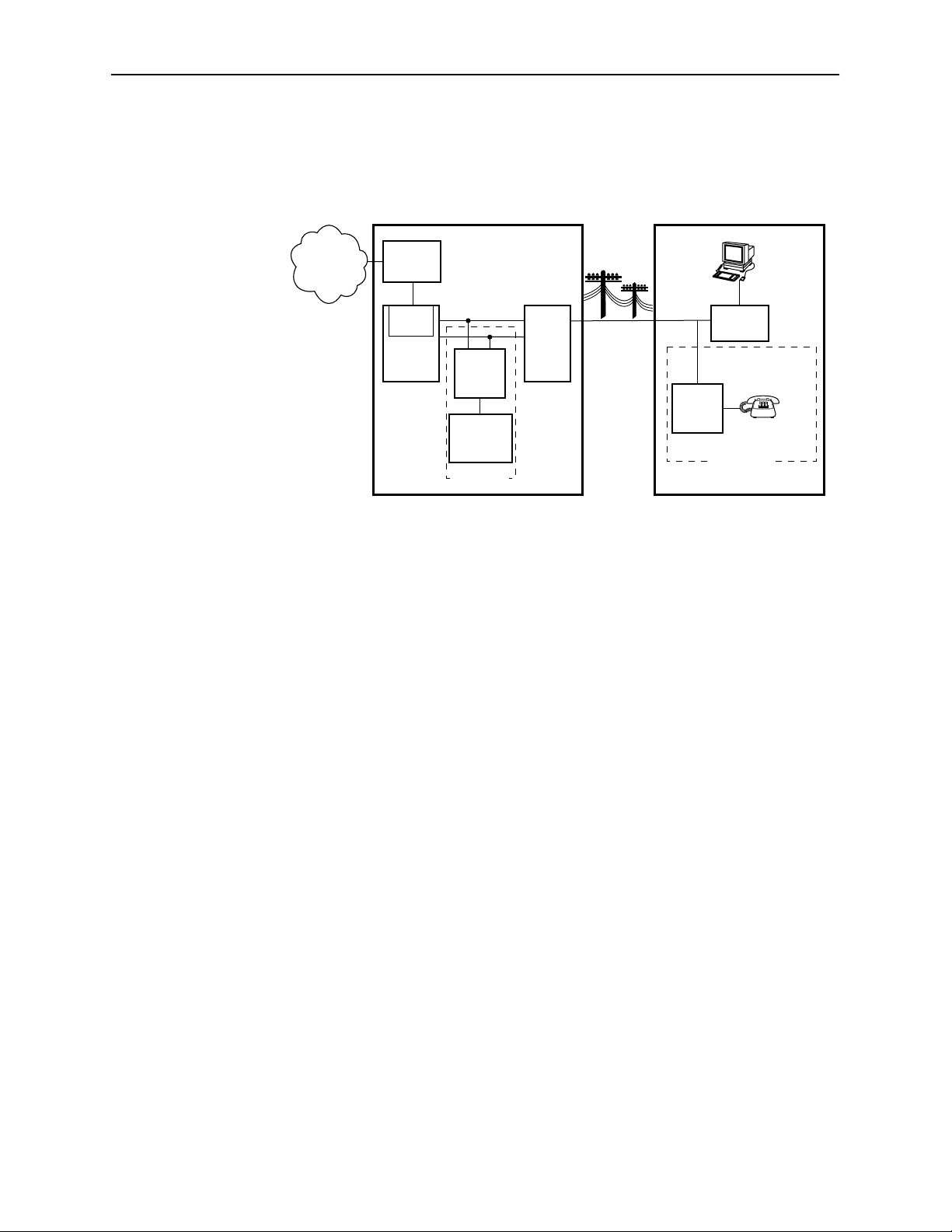
The following illustration shows a typical Hotwire configuration.
Central Office (CO)
Network
Service
Provider
Legend: DSL – Digital Subscriber Line IPC – Interworking Packet Concentrator
Hotwire
IPC
Ethernet
DSL
CARD
DSLAM
MDF – Main Distribution Frame POTS– Plain Old Telephone Service
SN – Service Node
CO
POTS
Splitter
Switched
Network
Optional
MDF
POTS/DSL
Customer Premises (CP)
Data
Interface
SN
POTS
CP
POTS
Splitter
Optional
Voice
Interface
99-15674-03
The DSL platform houses a Management Communications Controller (MCC) card
and up to 18 DSL cards (for example, 8540 RADSL cards, 8546 RADSL cards, or
a combination of cards). The DSL chassis interoperates with multiple types of
Hotwire Remote Termination Units (RTU) to deliver applications at multimegabit
speed in support of packet services over a Digital Subscriber Line (DSL) link.
The 8540 RADSL card interoperates with the following Hotwire RTUs:
H 5216
H 5246
The 8546 RADSL card interoperates with the following Hotwire RTU:
H 5446
NOTE:
If you would like more information on DSL-based services, applications, and
network deployment, refer to Paradyne’s DSL Sourcebook. The book may be
ordered by calling 1-800-PARADYNE or from the Paradyne website at
www.paradyne.com.
1-2
April 2000
8000-A2-GB20-50
Page 13
Hotwire DSL Chassis
Hotwire DSL System Description
There are four types of chassis:
H The Hotwire 8600 DSLAM chassis is an independent, standalone system.
The stackable design provides for up to six chassis to share management
access through a single MCC card, which in turn, allows an additional slot for
a DSL card in each of up to five additional chassis. For more information, see
the Hotwire 8600 Digital Subscriber Line Access Multiplexer (DSLAM)
Installation Guide.
OK
Alrm
TestTXRX
Col12
3
IN
DSL PORT
DSL PORT
MANAGEMENT
OUT SERIAL
4
3
4
LAN/WAN SLOT
3
2
MCC 1
SYSTEM
ETHERNET
OK
Alrm
TestTXRX
ETHERNET
TestTXRX
ETHERNET
FAN
5
46
.
.
ALM
.
1
.
STACK
POSITION
PWR
A
Col12
Col
B
SYSTEM
OK
RTN48V
AC
INPUT
AAB B
48VDC CLASS 2 OR
LIMITED PWR SOURCE
ESD
SYSTEM
DC FUSES
T4A, MIN. 48V
A
Alrm
3
2
B
8546
RADSL
3
8546
RADSL
2
8000
MCC
LINE
1
98-15350-02
H The Hotwire 8610 DSLAM chassis offers the same benefits as the 8600
chassis, with the added capability of accepting future high-density DSL cards
(5–25 ports). Management access is through the MCP card. For more
information, see the Hotwire 8610 DSLAM Installation Instructions.
8610
ESDESD
AC
INPUT
TM
TestTXRX
ETHERNET
Test
ETHERNET
DC FUSES
T4A, MIN. 48V
A
B
Col1234
RX
Coll
TX
FAN
ALM
A
DSL PORT
PWR
ALM INTF
10 BASE T
2
MCP/1
MANAGEMENT
5
6
4
3
2
1
B
STACK
OUTIN SERIAL
POSITION
MCP/
DSL
48VDC CLASS 2
OR LIMITED
PWR SOURCE
SYSTEM
SYSTEM
48VARTN
OK
Alrm
Alrm
OK
ABB
3
2
8546
RADSL
1
8000
MCP
3
TM
99-16311-01
In a stacked configuration, the first or base chassis must contain an MCC
card for 8600 or MCP card for 8610 in Slot 1. The 8600 and 8610 chassis
can be mixed in a stack. In addition to the MCC card, the base chassis can
house up to two DSL cards. Each additional chassis in the stack houses up
to three DSL cards.
8000-A2-GB20-50
April 2000
1-3
Page 14

Hotwire DSL System Description
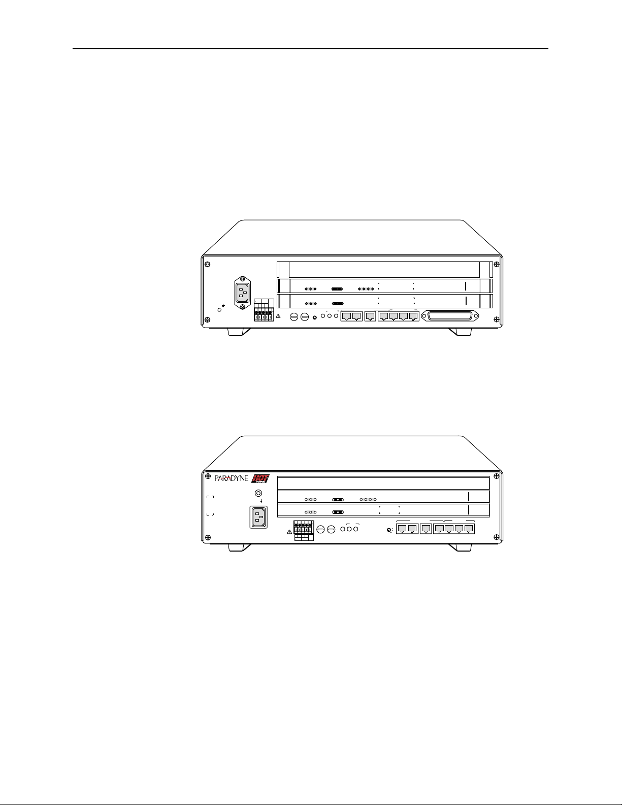
H The Hotwire 8800 DSLAM chassis is a 20-slot chassis designed to house up
to 18 4-port DSL cards and one MCC card. (The remaining slot is reserved
for the future use of a redundant MCC card.) For more information, see the
Hotwire 8800 Digital Subscriber Line Access Multiplexer (DSLAM) Installation
Guide.
H The Hotwire 8810 DSLAM chassis is a higher density carrier, for use with
future high-density port cards, as well as lower density cards (4 ports or less).
This 20-slot chassis with integral power, alarm, cooling, and interface
subsystems is designed to house up to 18 DSL cards and one MCC or MCC
Plus card. (The remaining slot is reserved for the future use of a redundant
MCC Plus card.) For more information, see the Hotwire 8810 DSLAM
Installation Instructions.
1-4
April 2000
8000-A2-GB20-50
Page 15
Hotwire DSL System Description
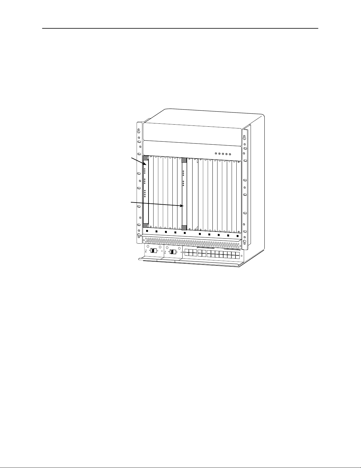
H The Hotwire 8820 GranDSLAM is a 20-slot chassis with integral power,
alarm, cooling, and interface subsystems designed to house up to 17 DSL
cards, as well as an SCM card for aggregating DSL traffic to an ATM uplink
and an MCP card. Layer 3 systems do not use SCM card functionality. Also
for Layer 3 systems, the 8820 GranDSLAM houses 8546 cards only, not
8540 cards. For more information, see the Hotwire GranDSLAM Installation
Guide.
POWER
DSL
Card
MCP
Card
SYSTEM
OK
Alm
Test
E
T
H
E
R
N
E
T
TX
RX
Coll
DSL PORT
1
2
3
4
S
Y
STE
M
O
K
Alm
Test
E
T
H
E
R
N
E
T
TX
R
X
C
oll
ALARMS
A
FanB
Major M
inor
DSL
PO
W
ER
EN
TR
Y
M
O
D
U
LE
L
EF
T U
N
IT: L
IN
E
A
R
IG
H
T U
N
IT: L
IN
E
B
48V RTN
WARNING!
POWER MUST BE DISCONNECTED AT THE SOURCE
BEFORE REMOVING OR INSTALLING THIS PWR ENTRY MODULE
48V NEG
48V RTN
WARNING!
BEFORE REMOVING OR INSTALLING THIS PWR ENTRY MODULE
P
O
W
E
R
E
NT
R
Y M
O
D
U
L
E
L
EF
T U
N
IT
: L
IN
E
A
RIG
H
T UN
IT
: L
IN
E
B
POWER MUST BE DISCONNECTED AT THE SOURCE
MCP
C
L
O
C
K
S
E
R
I
A
L
A
C
A
M
C
C
A
L
A
R
M
48V NEG
B
S
E
R
I
A
L
A
L
A
R
M
C
L
O
C
K
S
M
C
M
2
1
4
35
L
A
N
/
W
A
N
S
L
O
T
6
8
A
1
0
1
2
1
4
1
6
1
8
7
9
B
1
1
1
3
1
5
1
7
00-16573-01
Front View of a Hotwire 8820 GranDSLAM Chassis
8000-A2-GB20-50
April 2000
1-5
Page 16

Hotwire DSL System Description
MCC Card
The DSLAM and GranDSLAM chassis require one MCC card, which is a
processor card that administers and provides management connectivity to the
DSL cards. It acts as a mid-level manager and works in conjunction with a Simple
Network Management Protocol (SNMP) system, such as Paradyne’s OpenLanet
DCE Manager for HP OpenView, via its LAN port. It gathers operational status for
each of the DSL cards and responds to the SNMP requests. It also has a serial
port for a local user interface to the chassis. The following MCC cards are used in
the Hotwire chassis:
RADSL Cards
Use this MCC Card . . .
MCC, MCC Plus 8600, 8800, or 8810 DSLAM
MCP 8610 DSLAM or 8820 GranDSLAM
In this Hotwire Chassis. . .
For more information, see the Hotwire Management Communications Controller
(MCC) Card User’s Guide.
NOTE:
All references to MCC cards in this document refer to the MCC, MCC Plus
and MCP cards, unless specifically noted otherwise.
In addition to an MCC card, the chassis requires at least one DSL card, such as
an 8540 or 8546 RADSL card. These circuit cards contain RADSL ports, an
Ethernet interface to the Internet Service Provider (ISP), and a processor/packet
forwarder. The processor/packet forwarder controls the endpoints and forwards
the packet traffic via the Ethernet and RADSL interfaces.
When this card . . .
Fully populates this
Hotwire chassis . . .
Total number of DSL
ports supported is . . .
1-6
8540 or 8546 (4 ports)
8546 (4 ports) 8820 68
8600/8610 with 5 expansion
chassis
8800/8810 72
68
H 8540/8546 RADSL Cards – Contains four ports. RADSL cards are targeted
primarily for commercial environments and offer high-speed, rate-adaptive
services over copper wire. Applications such as Internet access, video
teleconferencing and LAN extension are supported.
April 2000
8000-A2-GB20-50
Page 17

Features
Levels of Access
Hotwire DSL System Description
The Hotwire DSL system provides the following features:
H High-speed Internet or intranet access.
H Rate Adaptive Digital Subscriber Line ports.
H Subscriber authentication, security access, and permission features that
prevent users from accessing unauthorized services.
H Status polling, alarm indicators and logging, diagnostics, and performance
capabilities.
H Primary network management support via SNMP agent for monitoring and
traps; Telnet for configuration and diagnostics.
H Dynamic IP addressing, allowing Network Service Providers the ability to
reuse IP addresses.
There are two levels of diagnostic/administrative access in the Hotwire DSLAM
system:
H Administrator
The Administrator has complete read/write access to the DSLAM system.
With Administrator permission, you can set specific parameters and variables
to configure cards, ports, interfaces, user accounts, next hop routes, and
SNMP security .
H Operator
The Operator has read-only access. With Operator permission, you can view
card status, physical layer status, interfaces, and Internet Protocol (IP)
routes, and run nondisruptive tests.
Software Functionality
Depending upon your system access, you can:
H Configure the system,
H Monitor the system, and/or
H Run applications and diagnostic tests to troubleshoot the network.
8000-A2-GB20-50
April 2000
1-7
Page 18

Hotwire DSL System Description
Configuring the DSL Cards
The Hotwire DSL software provides DSL configuration options to:
H Configure the DSL cards and RTU connectivity
H Configure the interfaces and ports
H Set up user accounts
H Upload or download a copy of a card’s configuration data to or from a Trivial
File Transfer Protocol (TFTP) server
H Download a new version of the DSL and RTU software
H Define an IP routing table
H Define and enable filters to prevent unauthorized network access
H Configure the SNMP agent to send traps to a specific SNMP NMS manager
NOTE:
You must have Administrator permission to configure the system.
For more information about configuring the system, see Chapter 3, RADSL Card
Configuration.
Monitoring the DSL Cards
The Hotwire DSLAM software provides submenu options to monitor the activity of
the Hotwire DSL cards. The monitoring screens allow you to:
H List the status of active ports and interfaces in a card, as well as display
statistics about other physical layers and interfaces.
H Display network protocol statistics, such as information about an application
program assigned to a specific socket number, UDP statistics, TCP data and
connection statistics, IP statistics, ICMP packet statistics, SNMP statistics
including SNMP authentication statistics, HDLC statistics, and PPP statistics.
H Display information about the routing table and detailed information about
each routing entry.
H Display the current Address Resolution Protocol (ARP) table.
H Display information about the configured IP router filters.
Use the monitoring screens to help you gather pertinent information and isolate
potential problem areas. You can monitor the system with either administrator or
operator permission. For more information about monitoring the system, see
Chapter 4, Monitoring the Hotwire DSL System.
1-8
April 2000
8000-A2-GB20-50
Page 19

Troubleshooting and Diagnostics
The Hotwire DSL system provides DSL diagnostic submenu options that:
H Perform PING tests and display results
H Perform a BERT test
H Display selftest results for CPU, memories, and ports
H Show major alarms such as Selftest Failure, Processor Failure, and DSL or
Ethernet port failure
H Show minor alarms such as Config Error and thresholds exceeded for DSL
Margin and Error Rate or Link Down events
H Perform a trace route to an IP address to display a list of intermediate nodes
to the destination
H Run a nondisruptive packet echo test over the DSL line to an RTU
NOTE:
You must have Administrator permission to perform most of the
troubleshooting and diagnostic activities. However, you can run nondisruptive
tests as a user with Operator permission.
Hotwire DSL System Description
For more information about troubleshooting and diagnostics, see Chapter 5,
Diagnostics and Troubleshooting.
8000-A2-GB20-50
April 2000
1-9
Page 20

Hotwire DSL System Description
1-10
April 2000
8000-A2-GB20-50
Page 21

Hotwire Menus and Screens
Menu and Screen Formats
The Hotwire DSL System has an ASCII-based menu- and screen-driven user
interface system that enables the user to configure and monitor the Hotwire
cards. This section describes the components of a typical Hotwire menu and
screen.
2
8000-A2-GB20-50
April 2000
2-1
Page 22

Hotwire Menus and Screens
Components of a Hotwire Menu
A typical Hotwire menu format is shown below:
1
2
3
1. Menu Title is the top line of the menu window that displays the title of the
menu or submenu.
2. Menu List is the portion of the menu window that displays the list of menu
options. When selected, a menu option displays a submenu window or
screen.
3. Letter Navigation Keys are provided within a menu list. These keys provide
a convenient way (shortcut) to select a menu item.
For example, from the Hotwire – DSL menu illustrated above, you can simply
press the A key to select the Configuration menu item. The Configuration
menu appears. You can then press the A key to select the Card Status menu
item. This action displays the Card Status menu. (You can also use the arrow
keys on your keyboard to select a menu item. See Commonly Used
Navigation Keys on page 2-4 for more information.)
To back up one menu level, press Ctrl-z. To go to the Main Menu, press
Ctrl-a.
2-2
April 2000
8000-A2-GB20-50
Page 23
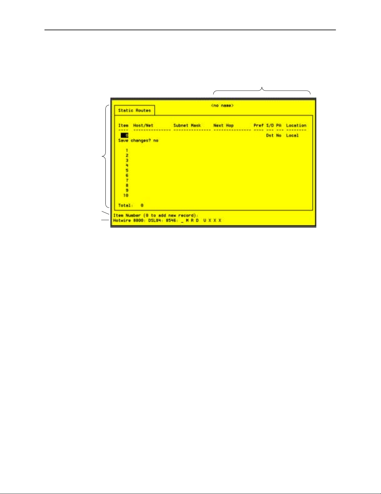
Components of a Hotwire Screen
A typical Hotwire screen looks like this:
2
Hotwire Menus and Screens
1
3
4
1. System Header Line is the top line of the screen. This line has two fields
that provide system login information.
— The first field displays the chassis name or the individual card name.
(Access the System Information screen by selecting the appropriate card
in the chassis and then follow this menu sequence: Configuration →Card
Status →Card Info.) If you do not define the system name, the DSL user
interface will display <no name>.
— The second field displays the current login. This field will display either
L:<user_login> or R:<user_login> where L indicates a local login,
R indicates a remote login, and <user_login> is the login account of
the user currently accessing the system. For example, if a user with a
login account called admin logs into the system using the local console,
this field will display L:admin.
2. Display Area is the top portion of the screen on which pertinent DSL system
information is displayed. This is also the portion of the screen on which fields
requiring input are displayed. However, you cannot enter values for the fields
in this portion of the screen. You must enter field values in the Input Line at
the bottom of the screen (see #3 below).
8000-A2-GB20-50
3. Input Line is the area of the screen where you are prompted to enter values
for the specific field that is highlighted on the screen.
For example, in the Static Routes screen above, the Item Number field is
highlighted. If you want to add a new record, you must enter 0 at the item
number (0 to add new record): prompt at the bottom of the screen.
April 2000
2-3
Page 24

Hotwire Menus and Screens
4. Status Line is the last line on the screen. This line displays status
information about the selected card.
For example, in the above illustration, the following line is displayed:
Hotwire 8610: DSL01: 8546: __ M __ D XXXX
The first field indicates the chassis type. In this case, the system in use is the
Hotwire 8610 DSLAM system. The second field indicates the card selected.
In this example, the DSL01 card is selected. The remaining fields indicate
card status information, such as whether or not an alarm is present and the
status of the Ethernet link. Similar information is displayed on the Card
Selection screen. For information about these fields, see Card Selection
Screen on page 2-11.
Commonly Used Navigation Keys
The following table lists navigation keys and their definitions. These commands
are used to move around the Hotwire DSL menus and screens.
Keys
Backspace, Del,
Ctrl-d
Ctrl-c Moves to top of current menu.
Ctrl-e Returns to the Card Selection screen from any screen.
Ctrl-r Resets counters (on monitoring statistics displays).
Ctrl-u Clears the current input or prompt line.
Ctrl-v Displays pop-up menus.
Esc h, ? Displays the online Help screen.
Esc l, Ctrl-l Refreshes the screen.
Esc n Goes to the next window.
Esc p, Ctrl-z Goes back to the previous window.
Esc t, Ctrl-a, Ctrl-t,
or Ctrl-y
Left arrow, Ctrl-b Moves the cursor to the left.
Right arrow, Ctrl-f Moves the cursor to the right.
Up arrow, Ctrl-p Moves up to the previous menu selection or entry field.
Down arrow, Ctrl-n Moves down or to the next selection.
Definition
Erases the character to the left of the prompt.
Goes back to the original, top-level window.
2-4
Enter or Return Accepts entry.
April 2000
8000-A2-GB20-50
Page 25

Levels of Access
Hotwire Menus and Screens
There are two levels of privileges on the Hotwire DSL system. Your user accounts
can be configured with a user name, password, and privilege of:
H Administrator. The Administrator has complete read/write access to the DSL
system. With Administrator permission, you can set specific parameters and
variables to configure cards, ports, interfaces, and endpoint selection.
H Operator. The Operator has read-only access and can view configuration
information and monitor performance but has no configuration menu access
or modification permission.
The default access is no login and password with Administrator status. To provide
login security to the DSL system, user accounts must be configured.
NOTE:
There must be at least one Administrator configured in order to have system
security.
For information on configuring user accounts, see the Hotwire Management
Communications Controller (MCC) Card User’s Guide.
8000-A2-GB20-50
April 2000
2-5
Page 26
Hotwire Menus and Screens
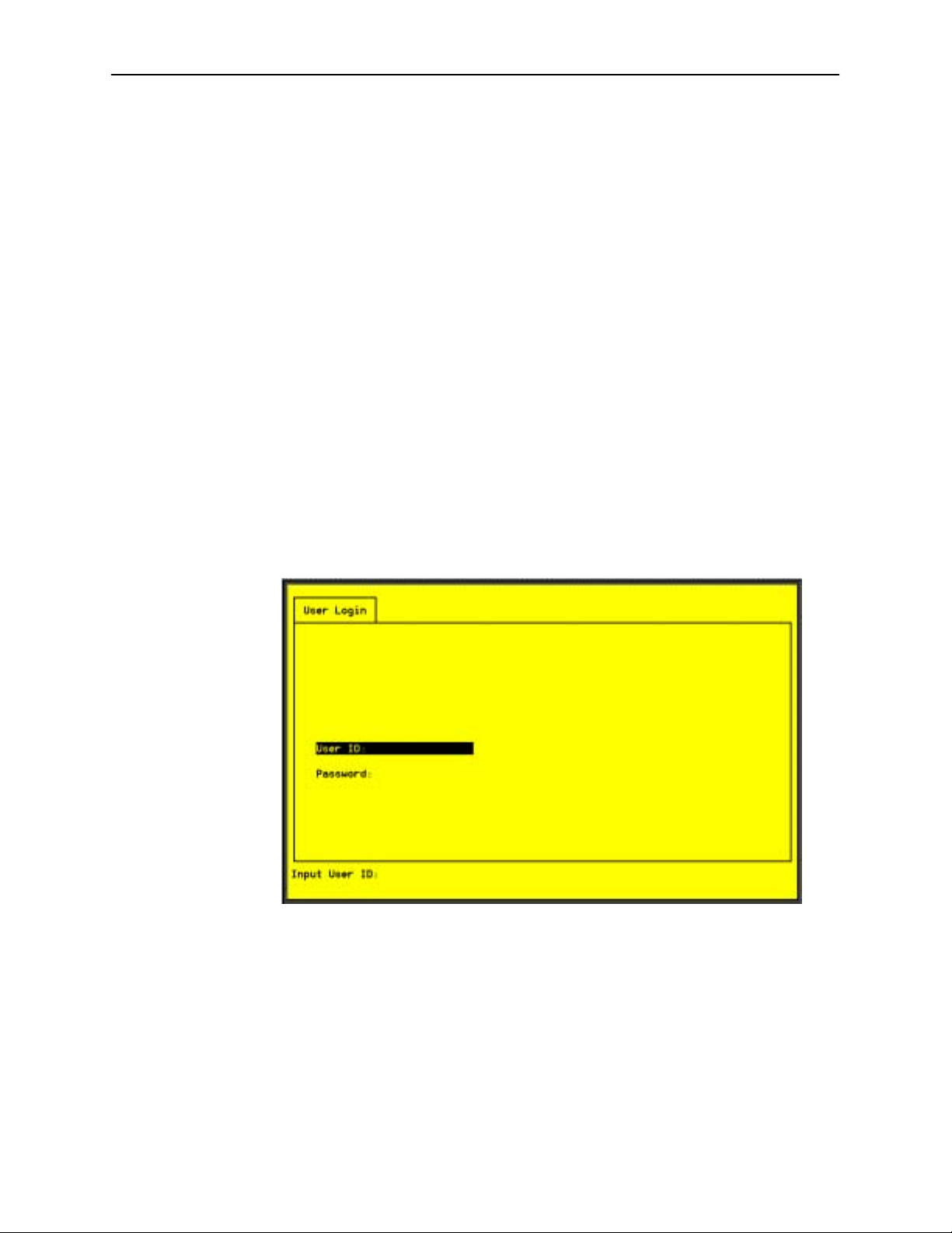
User Login Screen
You can log in to the Hotwire DSL system using either a local VT100- compatible
terminal or a remote Telnet connection. However, each card in the Hotwire DSL
system accepts only one login session at a time.
At the User Login screen, enter your login ID and password. You must wait until
your login is verified, anywhere from two seconds to 12 minutes. If you have
RADIUS Authentication, this verification takes some time while each RADIUS
server is contacted one at a time.
If you are denied access during a Telnet session, the session stops and an error
is logged. If you are using a console, return to the User Login screen.
NOTE:
The User Login screen only appears if one or more users have been defined
on the MCC.
NOTE:
If you forget your password, contact our Technical Service Center. Have the
serial number of the MCC card available, and the service representative will
provide you with a password.
2-6
The user ID and password are case-sensitive; that is, the system recognizes both
upper- and lowercase letters. For example, if you enter your user name and
password information in uppercase letters and your assigned user name and
password are in upper- and lowercase letters, the system will not let you log in.
User ID and password are limited to a maximum of 15 characters. Any user
account with a user ID or password exceeding 15 characters is treated as invalid
by the MCC.
After entering your user ID and password, the system displays the Hotwire
Chassis Main Menu.
April 2000
8000-A2-GB20-50
Page 27

Hotwire Menu Hierarchy
This section describes the menu structure of the Hotwire user interface.
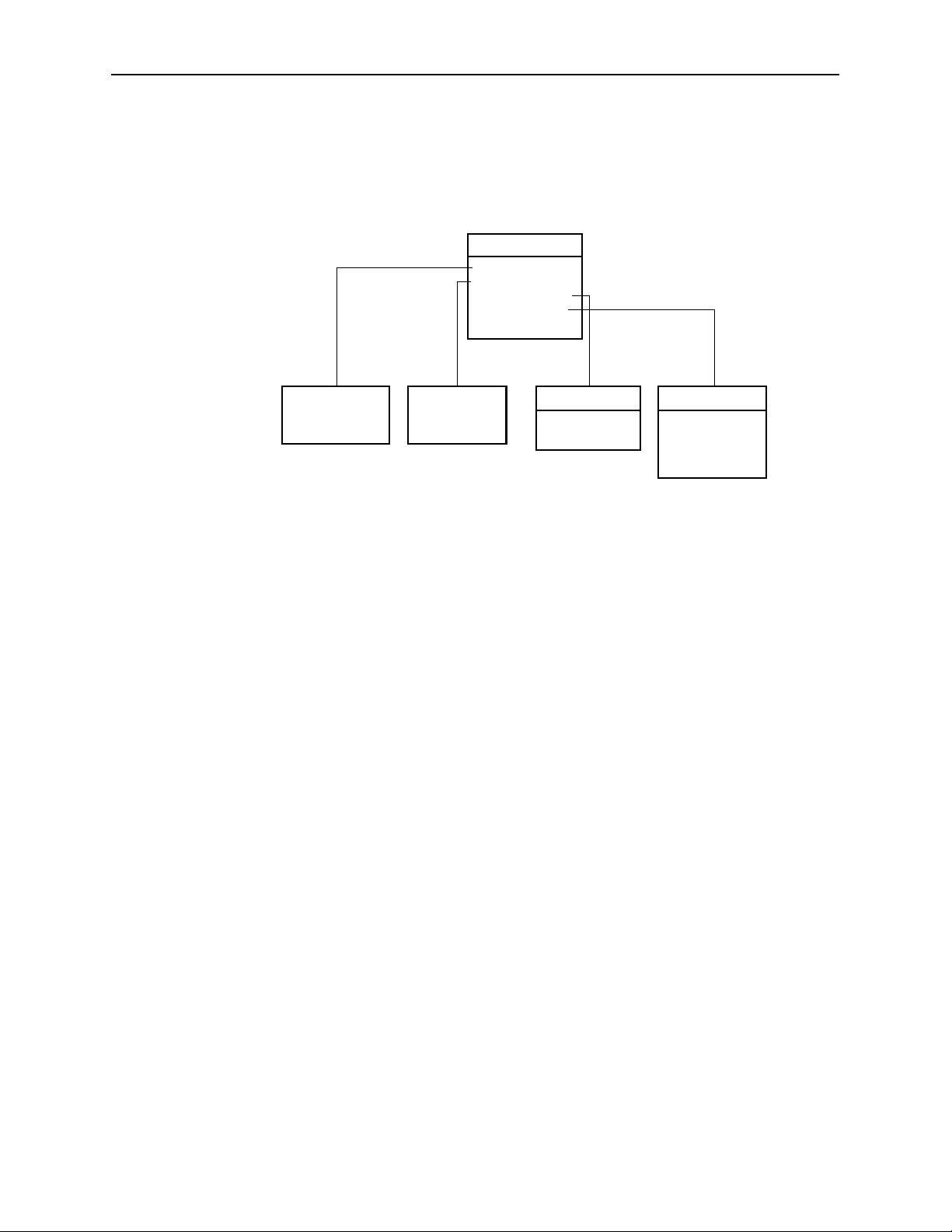
Hotwire Chassis Main Menu
The following illustration shows the Hotwire Chassis Main Menu.
Hotwire Chassis
A. Chassis Info
B. Card Selection
C. Logout
97-15566-01
From the Hotwire Chassis Main Menu, you can select:
H A. Chassis Info to enter or display chassis information, such as the chassis
name, name of person responsible for the system, and physical location of
the chassis.
Hotwire Menus and Screens
H B. Card Selection to select a particular card in the chassis. This screen also
displays status information about all cards in the chassis. The card you select
determines which Hotwire menu the system will display next (Hotwire – DSL
menu).
For more information, see Card Selection Screen on page 2-11.
H C. Logout to exit from the current Hotwire DSL login session.
For more information, see Exiting From the System on page 2-13.
For information on the MCC card, see the Hotwire Management Communications
Controller (MCC) Card User’s Guide.
8000-A2-GB20-50
April 2000
2-7
Page 28
Hotwire Menus and Screens
Hotwire – DSL Menu
After selecting a specific DSL card from the Card Selection screen, the DSL
system displays the Hotwire – DSL Menu.
Hotwire – DSL
A. Configuration*
B. Monitoring
C. Applications
D. Diagnostics
E. Exit
See
Configuration
Menu Below*
* The Configuration menu item appears only if you have
Administrator permission.
See
Monitoring
Menu Below
Applications
A. Ping
B. Trace Route
Diagnostics
A. Selftest
B. Alarms
C. Packet Echo
D. BERT Test
99-15563-04
From this menu, you can configure, monitor, and troubleshoot a specific DSL
card.
2-8
April 2000
8000-A2-GB20-50
Page 29
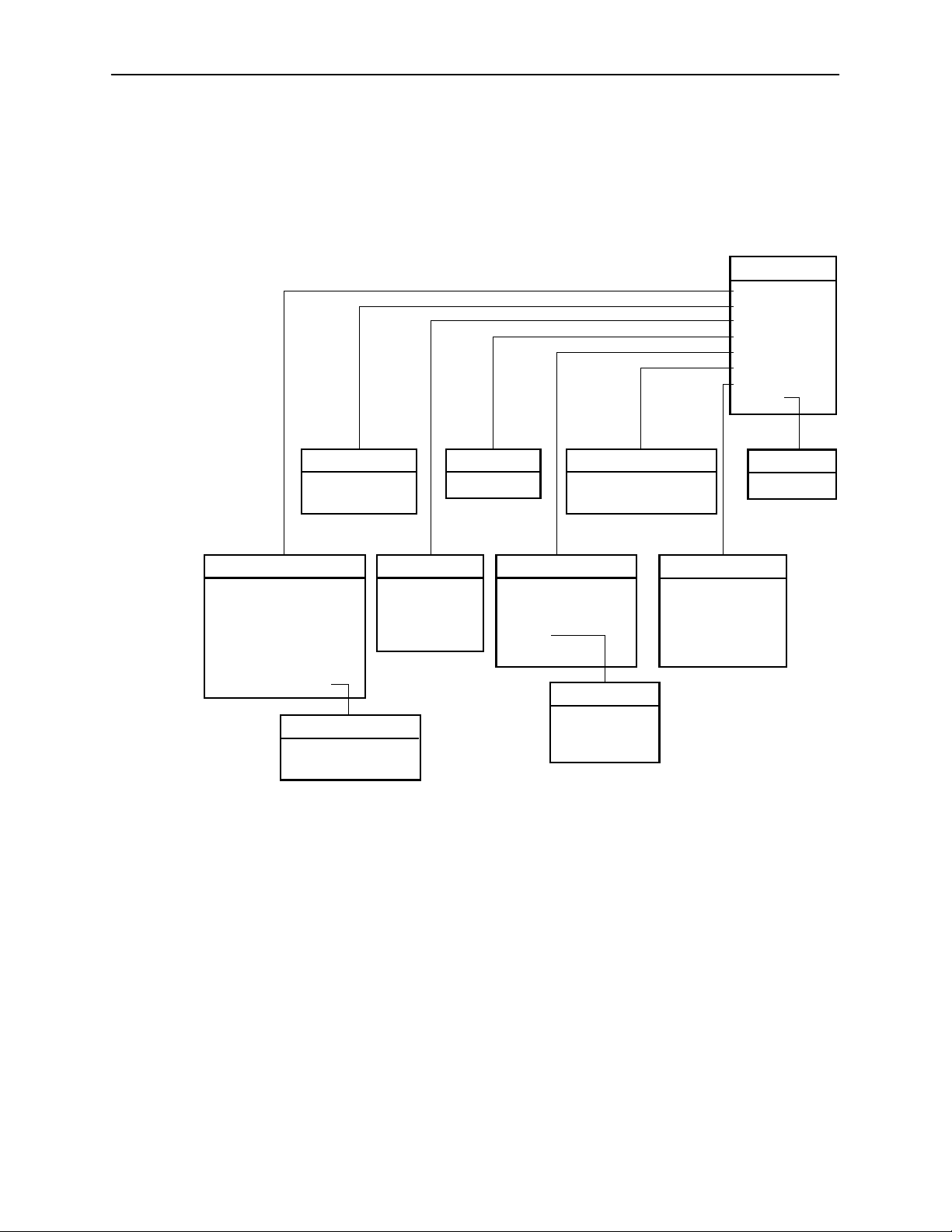
DSL Card Configuration Menu
The following figure illustrates the complete Configuration menu hierarchy from
the Hotwire – DSL menu.
Hotwire Menus and Screens
Configuration
A. Card Status
B. Ports
C. Interfaces
D. Users
E. IP Router
F. SNMP
G. DHCP Rela y
H. RTU
1
(B) Ports
A. Ethernet Port
B. DSL Ports
(A) Card Status
A. Card Info
B. DNS Setup
C.Time/Date
D.NVRAM Clear
E. NVRAM Cfg Loader
F. Card Reset
G.Download Code
(G) Download Code
A. Download Code
B. Apply Download
NOTE:
The Configuration menu and its submenus appear only when logging in to
the system with a user account that has Administrator permission.
(D) Users
A. Accounts
(C) Interfaces
A. General
B. IP Network
C Control
2
D. PPP
1
2
(F) SNMP
A. Security
B. Communities/Traps
(E) IP Router
A. Static Routes
B. Martian Networks
C. IP Router Filters
D. ARP
E. Host Table
(D) ARP
A. Parameters
B. Add Entry
C. Delete Entry
User Security on Model 8546
Not on Model 8540
(H) RTU
A. Selection
(G) DHCP Relay
A. Domain Names
B. Servers 1-4
C. Servers 5-8
D. Servers 9-12
E. Servers 13-16
99-15564-03
8000-A2-GB20-50
April 2000
2-9
Page 30
Hotwire Menus and Screens
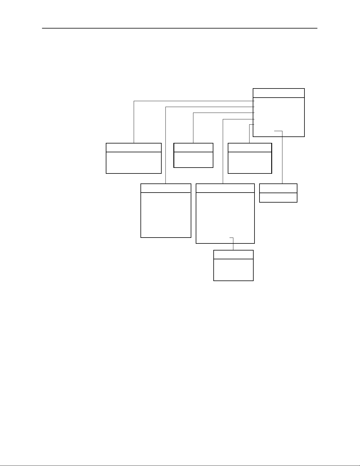
DSL Card Monitoring Menu
The following figure illustrates the complete Monitoring menu hierarchy from the
Hotwire – DSL menu.
Monitoring
A.Card Status
B.Physical Layer
C.Interfaces
D.Network Protocol
E.IP Router
F. RTU
(A) Card/CPE Status
A. Card Info
B. Login History
C. Syslog
Logging In to the System
(C) Interfaces
A. Active List
B. Status
(B) Physical Layer
A. Active List
B. Ether Statistics
C. HDLC Bus Stats
D. DSL Link Perf
E. DSL Perf Stats
F. DSL Error Stats
G. DSL Xmit Stats
*Not on Model 8540
(E) IP Router
A. Routing Table
B. ARP Table
C. Filter Table
(D) Network Protocol
A. Socket Statistics
B. UDP Statistics
C. TCP Statistics
D. IP Statistics
E. ICMP Statistics
F. SNMP Statistics
G. HDLC Statistics
H. PPP Stats*
(H) PPP Stats
A. General
B. LCP Stats
C. IPCP Stats
(F) RTU
(F) RTU config
A. Information
A. RTU Information
99-15565-03
2-10
This section describes how to log in to the Hotwire DSL system after the system
has been configured.
NOTE:
When you power on the system for the first time, the system displays the
Who Am I screen. This screen can be accessed only from the local console.
April 2000
8000-A2-GB20-50
Page 31

Card Selection Screen
Hotwire Menus and Screens
From the Hotwire Chassis Main Menu, select Card Selection to display the status
of any of the 18 DSL cards installed in the 8800/8810 chassis (or 17 DSL cards
installed in the 8820 GranDSLAM chassis) by type and slot number. The Card
Selection screen also displays general and interface status for each card.
NOTE:
The Card Selection screen for the Hotwire 8600/8610 chassis displays the
same information, but the slot order is different.
8000-A2-GB20-50
April 2000
2-11
Page 32

Hotwire Menus and Screens
The status of each DSL card is indicated by codes being displayed in any of eight
positions to the right of the card selected.
Column
Heading
Slt <slot number> M = MCC, MCP or MCC Plus card
Mdl # <card type> First four digits of the card model number:
Stat
Eth 4 U, D, or X Status of Ethernet link:
8546
(DSL
card)
WAN Lnk For M/SDSL and M/HDSL cards.
NOTE:
If an option is not active, an underscore is shown in its place.
Position Display Description
1–18 = slot number for DSL card
8540 = 8540 RADSL card
8546 = 8546 RADSL card
8000 = MCC/MCP/MCC Plus card
1 T or _ Test mode. Card currently in test mode or _ for
no active test.
2 M or _ Major alarm. Major alarm present on card or _
for no active major alarm.
3 R or _ Minor alarm. Minor alarm present on card or _
for no minor alarm active.
U=Up, D=Down, X=Disabled
5 and up U, D, X, or H Status of DSL card Port 1–4 link:
U=Up, D=Down, X=Disabled, or
H=Handshaking
For example, if you select DSL card in Slot 4, the following may be displayed:
4: 8546 _MRD UXXX
Position: 1234 5678
This display shows the following:
H There is an 8546 card in Slot 4
H Position 1 – no current test (_)
H Position 2 – major alarm is present (M)
H Position 3 – minor alarm is present (R)
H Position 4 – Ethernet link is down (D)
H Position 5 – DSL port 1 is up (U)
H Positions 6, 7 and 8 – DSL ports 2, 3 and 4 are disabled (X)
On the Card Selection screen, there is a prompt used to select a specific card in
the DSL chassis. When a DSL slot number is entered, you are connected to the
DSL card you selected.
For more information about the status displayed on this screen, such as major
and minor alarms, see Troubleshooting in Chapter 5, Diagnostics and
Troubleshooting.
2-12
April 2000
8000-A2-GB20-50
Page 33

Accessing the Hotwire – DSL Menu
Procedure
"
To access the Hotwire – DSL menu:
1. From the Hotwire Chassis Main Menu, select Card Selection.
The Card Selection screen appears.
2. Verify that the DSL card you want to access appears on the Card Selection
screen. (See Card Selection Screen on page 2-11 for more information.)
3. At the Goto Card (MCC or DSLnn): prompt, type the number of the slot.
Then, press Enter. For example, if you want to configure the DSL card in
Slot 13, type 13.
The Hotwire – DSL menu appears.
Exiting From the System
You can manually log out of the system or the system will automatically log you
out.
Hotwire Menus and Screens
Manually Logging Out
Procedure
"
To exit from the Hotwire DSL system:
1. Return to the Card Selection screen by selecting Exit from either the Hotwire
– MCC menu or the Hotwire – DSL menu.
2. Press Ctrl-z.
3. From the Hotwire Chassis Main Menu, select Logout.
The system exits from the current Hotwire DSL login session.
Automatically Logging Out
The DSL system has an automatic timeout feature that logs you out of the system
after five minutes (on MCC) or ten minutes (on DSL port card) of inactivity. You
will need to log back in to continue your work.
To log back in, press Enter to display the Operator Login screen and log in.
8000-A2-GB20-50
April 2000
2-13
Page 34

Hotwire Menus and Screens
This page intentionally left blank.
2-14
April 2000
8000-A2-GB20-50
Page 35

RADSL Card Configuration
Overview
This chapter describes configuration options on the 8540/8546 RADSL cards.
Use these options to customize your applications. For information on customizing
the MCC card, see the Hotwire Management Communications Controller (MCC)
Card User’s Guide.
NOTE:
Certain parameters such as speeds are dependent on the settings on the
RTU Configuration screen. Go to Configuration →RTU Config →Selection
(A-H-A) and select your RTU type for each port before any additional
configuration activities.
3
Port Naming Conventions
The following are the naming conventions used for the Hotwire DSL interfaces:
NOTE:
Interfaces are sometimes referred to as ports. The term ports, however,
usually is reserved for referring to the physical layer attributes of an interface.
H e1a – Interface name of the DSLAM system 10BaseT interface on the MCC
and DSL cards.
H s1b – Interface name of the MCC and DSL card’s interface to the DSL
system backplane bus.
H s1c, s1d, s1e, and s1f – Interface names of the four DSL ports on a RADSL
card.
NOTE:
These names are used throughout the remainder of this guide to reference
the Hotwire DSL interfaces. These are also the names used in the Hotwire
DSL software when configuring the Hotwire DSL system.
8000-A2-GB20-50
April 2000
3-1
Page 36

RADSL Card Configuration
g
Configuring the MCC Card, DSL Cards, and RTUs
Use the procedures in the following order to configure the MCC card and
RADSL cards for the basic setup for terminal management and user data
connectivity.
NOTE:
It is assumed that you have read the Hotwire 8540 and 8546 RADSL Cards
Network Configuration Guide and have assigned service and management
domain IP addresses for all devices (MCC, DSL, and RTUs).
The following tables list the basic steps you need to do to configure the MCC
cards, DSL cards, and RTUs.
For the Management Domain,
perform task . . .
1. Configure time and date. MCC
2. Assign the IP address to the
backplane on the MCC card.
3. Assign the IP addresses to the
DSL cards.
4. Create SNMP Community Strings
and Authentication Failure Trap.
5. Create default route. MCC
6. Reset the MCC card. MCC
7. Select a DSL card to configure. DSL Card Selection Screen in Chapter 2,
8. Configure 5446 RTU IP host
address for the 8546 RADSL
card. (Not applicable to 8540
RADSL card.)
On the . . . See the . . .
Hotwire Management
MCC
MCC
MCC
DSL DSL Card Configuration Interfaces
Communications Controller (MCC)
Card User’s Guide
Hotwire Menus and Screens.
Screens, page 3-15 (A-C-B).
For each Service Domain,
perform task . . .
1. Configure a static route to the
NMS.
2. Assign IP addresses to the DSL
card LAN.
3. Reset the DSL card. DSL DSL Configuration Card Status
4. Create DHCP Relay Agent. DSL Configuring DHCP Relay Agent
5. Create default route or source
route on DSL.
6. Create SNMP Community Strings
and Authentication Failure Trap.
7. Configure RTU Information DSL DSL Configuration RTU Screens,
3-2
April 2000
On the . . . See . . .
DSL DSL Configuration IP Router
Screens, page 3-20 (A-E-A).
DSL DSL Card Configuration Interfaces
Screens, page 3-15 (A-C-B).
Screens, page 3-7 (A-A-F).
(dynamic addressing),
page 3-29 (A-G).
DSL DSL Configuration IP Router
Screens, page 3-20 (A-E-A).
DSL DSL Configuration SNMP Screens,
page 3-26 (A-F-B).
page 3-31 (A-H-A).
8000-A2-GB20-50
Page 37

The following illustrates the management domain components that must be
configured and examples of the various naming conventions for the 8546 card.
Tasks refer to those listed in the table on page 3-2.
MANAGEMENT DOMAIN
RADSL Card Configuration
DCE Manager
Server
10BT
DCE Manager
Router
b1: 135.1.3.254/
255.255.255.0
b2: 135.1.2.1/
255.255.255.0
Port Names
Task 3
* Only the 5446 RTU requires
an IP address in the
management domain
IP Address
e1a: 135.1.2.2/
255.255.255.0
MCC Card
s1b: 135.1.3.1/
255.255.255.0
System Backplane
s1b: 135.1.3.2/
255.255.255.0
8546
RADSL
Card
IP Interface
DSLAM
s1c
s1d
s1e
s1f
DSL
DSL
RTU*
a: 135.1.3.3/
255.255.255.255
Task 2
RTU*
a: 135.1.3.4/
255.255.255.255
Task 8
Task 8
99-15561-02
8000-A2-GB20-50
April 2000
3-3
Page 38

RADSL Card Configuration
The following illustrates the management domain components that must be
configured and examples of the various naming conventions for the 8540 card.
Tasks refer to those listed in the table on page 3-2.
MANAGEMENT DOMAIN
DCE Manager
Server
DCE Manager
Router
b1: 135.1.3.254/
255.255.255.0
b2: 135.1.2.1/
255.255.255.0
Port Names
Task 3
10BT
IP Address
e1a: 135.1.2.2/
255.255.255.0
MCC Card
s1b: 135.1.3.1/
255.255.255.0
System Backplane
s1b: 135.1.3.2/
255.255.255.0
8540
RADSL
Card
IP Interface
DSLAM
s1c
s1d
s1e
s1f
DSL
DSL
Task 2
RTU
RTU
3-4
April 2000
99-16360
8000-A2-GB20-50
Page 39

RADSL Card Configuration
The following illustrates the service domain components that must be configured
and examples of the various naming conventions for the 8546 card. Tasks refer to
those listed in the table on page 3-2.
SERVICE DOMAIN
ISP Router
a: 155.1.2.1/
255.255.255.0
b1: 155.1.3.1/24
b16: 170.1.3.1/
255.255.255.0
* Only the 5446 RTU requires IP
addresses in the service domain
.
.
.
Tasks 2, 4 & 6
MCC Card
System Backplane
8546
RADSL
Card
IP Interface
e1a:
155.1.3.2/
156.1.3.2/
.
.
.
170.1.3.2/
255.255.255.0
DSLAM
s1c
s1d
s1e
s1f
DSL
DSL
RTU*
b1: 155.1.3.3/
b2: 156.1.3.3/
b3: 157.1.3.3/
b4: 158.1.3.3/
255.255.255.0
RTU*
b1: 159.1.3.3/
b2: 160.1.3.3/
b3: 161.1.3.3/
b4: 162.1.3.3/
255.255.255.0
10BT
10BT
99-15562-02
8000-A2-GB20-50
April 2000
3-5
Page 40

RADSL Card Configuration
The following illustrates the service domain components that must be configured
and examples of the various naming conventions for the 8540 card. Tasks refer to
those listed in the table on page 3-2.
SERVICE DOMAIN
ISP Router
a: 155.1.2.1/
255.255.255.0
b1: 155.1.3.1/24
b16: 170.1.3.1/
255.255.255.0
.
.
.
Tasks 2, 4 & 6
MCC Card
System Backplane
8540
RADSL
Card
IP Interface
e1a:
155.1.3.2/
156.1.3.2/
.
.
.
170.1.3.2/
255.255.255.0
DSLAM
s1c
s1d
s1e
s1f
DSL
DSL
RTU
RTU
99-16361
3-6
April 2000
8000-A2-GB20-50
Page 41

DSL Configuration Card Status Screens
Use the system information submenu of the Card Status screens to configure
basic DSL card-level information.
RADSL Card Configuration
NOTE:
Only a user who logs on to the Hotwire DSL system with Administrator
permission can configure the DSL card.
" Procedure
To configure card information, DNS setup, time/date, clear NVRAM, upload or
download configuration sets, download new firmware, or reset card:
1. Follow this menu sequence:
Configuration →Card Status (A-A)
2. The Card Status menu appears. Enter the desired value on each selected
screen and field as shown in Table 3-1 and press Enter.
8000-A2-GB20-50
April 2000
3-7
Page 42

RADSL Card Configuration
Table 3-1. Card Status Options (1 of 4)
Card Info (System Information) A-A-A
Allows you to configure basic card-level information.
Card Name – 16 alphanumeric characters. Name assigned to the card.
Card Contact – 32 alphanumeric characters. Name or number of party responsible for
card.
Card Location – 16 alphanumeric characters. Location assigned to the card.
Router ID – nnn.nnn.nnn.nnn format. (This field is read-only.) Diagnostic Domain IP
address assigned to card by the MCC.
Router Subnet Mask – nnn.nnn.nnn.nnn format. (This field is read-only.)
Local Control T erminal Port Mode – Either Standard (for USA keyboards) or
Extended (for European keyboards). (Default = Standard).
Remote Control Terminal Port Mode – Either Standard (for USA keyboards) or
Extended (for European keyboards). (Default = Standard).
T elnet daemon tcp port – 0–65536 (Default = 23). If you change this field, you need to
do a card reset.
DNS Setup (Configure DNS) A-A-B
Gives the user the ability to configure the access to DNS servers from which name to IP
address translation requests are made.
DNS Servers – Enter the primary Domain Name System Server address in
nnn.nnn.nnn.nnn format (up to three).
Default Domain Name – 40 characters. Domain used for queries that are not fully
qualified. For example, if the default domain name = paradyne.com and a Telnet is
attempted to reach a system called gemini, the card would query the DNS server for
gemini.paradyne.com.
Time to wait for response (secs)? – 1–300 seconds (Default = 5). Enter the time to
wait for a response.
Number of times to retry server – 1–10 times (Default = 5). Enter the number of times
to retry the server.
3-8
April 2000
8000-A2-GB20-50
Page 43

RADSL Card Configuration
Table 3-1. Card Status Options (2 of 4)
Time/Date A-A-C
Gives the user the ability to configure the local time and date on the 8540 RADSL card
with network time and to synchronize the DSL system’s clock via a Network Time
Protocol (NTP) server.
On the 8546 card, displays the time zone, local time, and date on the DSL card as
received from the MCC card.
NOTE: At system boot time, the time on the DSL cards automatically synchronizes
Time zone – Name of the system’s time zone (Default = GMT). See the Help for a list of
time zones.
Local Time/Date – Time in hh.mm format (am or pm). Enter the date in mm/dd/yy
format.
Client NTP Mode – Broadcast/Unicast (Default = Broadcast). For the 8540 card, select
the Client Network Time Protocol (NTP) Mode.
NTP Server – nnn.nnn.nnn.nnn format. For the 8540 card, enter the NTP Server IP
address. May be left blank since card will automatically synchronize with the MCC card,
which should have the NTP server address.
Synchronized(hrs) – 1–24 (Default = 1). For the 8540 card, enter the hours between
synchronization.
with the MCC card. Therefore it is usually not necessary to use this screen
on the DSL card.
NVRAM Clear Screen (Clear NVRAM) A-A-D
Clears out the Non-Volatile RAM (NVRAM) in order to reuse the card or to reconfigure
the current card.
CAUTION: If you select yes on this screen, you will permanently remove most of
the configuration information you have stored on this card and all IP
addresses and routing tables will have to be re-entered. The system will
perform a reset and return to the factory configuration.
8000-A2-GB20-50
April 2000
3-9
Page 44

RADSL Card Configuration
Table 3-1. Card Status Options (3 of 4)
NVRAM Config Loader A-A-E
Provides the ability to upload or download a copy of the card’s binary configuration data
to or from a Trivial File Transfer Protocol (TFTP) server.
Configuration File Name –The file name may be a regular path name expression of
directory names separated by a forward slash (/) ending with the file name. The total
path name length must be less than 40 characters. If the TFTP server is hosted by a
DOS machine, then directory and file names must follow the 8.3 naming convention
imposed by DOS.
TFTP Server IP Address – IP host name or address in nnn.nnn.nnn.nnn format.
TFTP Transfer Direction – Upload-to-Server/Download-to-Server (Default =
Upload-to-Server). Select Upload-to-Server to store a copy of the card’s configuration
on the server. Select Download-to-Server to have the file server send a copy of the
stored configuration file to the card.
Start Transfer – Yes/No (Default = No).
DOS Machine
If your server is hosted by a DOS machine, you must name the file to be uploaded
using the DOS convention eight-character length. The system will automatically
upload the configuration file and create directories and file names as needed.
UNIX Machine
If your server is hosted by a UNIX machine, the configuration file you name will not
be created on the UNIX system by the TFTP server. It is critical that you work with
your system administrator to plan the naming conventions for directories, filenames,
and permissions so that anyone using the system has read and write permissions.
(This is a UNIX system security feature.)
NOTE: This must be done before you can upload files to a UNIX server.
Packets Sent – Number of packets sent in download.
Packets Received –
Bytes Sent – Number of bytes sent in download.
Bytes Received – Number of bytes received in download.
Transfer Status – Status of the upload or download transfer.
Card Reset (Reset System) A-A-F
Resets the card. This resets all counters and if a new configuration or software version
has been downloaded, the new code will then become active. Verify that the LEDs on
the DSL card go through the reset sequence once, and then a second time after
approximately 10 seconds (BOOTP).
NOTE: This action disrupts the data flow for at least 30 seconds.
Number of packets received in download.
3-10
April 2000
8000-A2-GB20-50
Page 45

RADSL Card Configuration
Table 3-1. Card Status Menu Options (4 of 4)
Download Code (Download Code and Apply Download) A-A-G
Provides the ability to download a new version of code and apply the downloaded code.
For further information on this feature, see Appendix A, Download Code.
Select Download Code (A) or Apply Download (B). You must exit this screen and use
the Apply Download screen.
Download Code A
Allows code download. This screen is similar to the NVRAM Config Loader screen.
Image File Name – The file name may be a regular pathname expression of directory
names separated by a forward slash (/) ending with the file name. The total pathname
length must be less than 40 characters. If the TFTP server is hosted by a DOS
machine, then directory and filenames must follow the 8.3 naming convention imposed
by DOS.
TFTP Server IP Address – IP host name or address in nnn.nnn.nnn.nnn format.
Start Transfer – Yes/No (Default = No).
Packets Sent – Number of packets sent in download.
Packets Received – Number of packets received in download.
Bytes Sent – Number of bytes sent in download.
Bytes Received – Number of bytes received in download.
Transfer Status – Status of the download transfer.
Once the download is complete, press Ctrl-z to exit back to the Download Code
submenu and select Apply Download (A-A-G-B) for the download to take effect.
Apply Download B
This selection applies the downloaded code and drops all connections by performing a
device reset. This screen is used to overlay the previously downloaded image for the
card. If you select yes at the Reset System prompt, the system goes through a system
restart and interrupts service on the card. For further information on this feature, see
Appendix A, Download Code.
NOTE: This option does not apply if the download to the DSL card was initiated
from the MCC. Also, if you have not previously downloaded code, then you
will not be able to access this selection.
8000-A2-GB20-50
April 2000
3-11
Page 46

RADSL Card Configuration
DSL Configuration Ports Screens
Use the system information submenu of the Ports screens to display the DSL
Ports screen.
" Procedure
To configure DSL ports:
1. Follow this menu sequence:
Configuration →Ports (A-B)
2. The Ports menu appears. Enter the desired value on each selected screen
and field as shown in Table 3-2 and press Enter.
Table 3-2. Ports Options (1 of 3)
Ethernet Port A-B-A
Allows you to configure the Ethernet Port for full or half-duplex mode.
Port Name – Enter the port name (up to 7 characters).
Full Duplex – Enable for Full Duplex mode, Disable for half duplex mode
(Default = Disable).
Action – Edit/Reset. Select Reset to have changes become active.
3-12
April 2000
8000-A2-GB20-50
Page 47

RADSL Card Configuration
Table 3-2. Ports Options (2 of 3)
DSL Ports (DSL Parameters) A-B-B
Allows configuration of the operational and alarm parameters of the DSL ports. Each
DSL port is configured separately .
Action – Edit to configure the DSL ports. Reset the port to make changes active.
Port # – Enter port 1 to 4 (Default = 0).
RTU Type – Model number of the service node. For Model 8540, selections are
5246/5216 (Default = 5216). For Model 8546, selections are 5446r1/5446r2 (Default =
5446r2). (This field is read-only .)
Port Desc – Enter port description, such as user name, etc. (40 characters maximum).
Tx Power – 0 dB, –3 dB, –6 dB. For the RADSL card. Enter the rate that allows you to
reduce the transmit power by: –3 dB or –6 dB (Default = 0 dB). Short loops require less
power, reducing crosstalk and giving better performance on longer loops in the same
cable bundle.
RTU Tx Power – 0 dB, –3 dB, –6 dB, –9dB. From the RTU. Enter the rate that allows
you to reduce the transmit power by: –3 dB or –6 dB (Default = –6 dB).
Startup Margin – The Startup Margin (SM) field is used to determine the quality of the
connection of the upstream link on system startup. It is used in conjunction with the
adaptive speed fields to determine the initial line speeds of the DSL link. The value is
between –3 and 9. In Adaptive Mode, if the margin falls below SM, the DSL link will be
restarted at a slower speed. If the calculated margin of the next speed is greater than
SM by 3 dB, the speed will increase. Enter –3 to 9 (Default = 3).
Reed-Solomon Interleaving – Long/Short (Default = Long).
Behavior – Fixed/Adaptive (Default = Adaptive). In fixed rate mode, the DSL port will
operate at the specified upstream and downstream speed. In rate adaptive mode, the
rates will not exceed the maximum speed and traps are sent when the links drop below
the minimum, as the transmission characteristics of the loop change.
Fixed: Dn Speed* – 7168/6272/5120/4480/3200/2688/2560/2240/1920/1600/1280/
1024/960/896/768/640/512/384/256 (Default = 2560 kbps).
Fixed: Up Speed* –
1088/952/816/680/544/476/408/340/272/204/136/119/102/90.6/85/68/51/45.3/34/11.3
(Default = 1088 kbps). Enter the fixed upstream speed.
Adaptive: Max Dn Speed* – 7168/6272/5120/4480/3200/2688/2560/2240/1920/1600/
1280/1024/960/896/768/640/512/384/256 (Default = 7168 kbps). Enter the maximum
downstream speed.
8000-A2-GB20-50
* If you select a downstream speed of 2560 or higher, your upstream speed selection is
limited to 1088/952/680/408 kbps.
April 2000
3-13
Page 48

RADSL Card Configuration
Table 3-2. Ports Options (3 of 3)
DSL Ports (DSL Parameters) (cont’d) A-B-B
Adaptive: Max Up Speed* –
1088/952/816/680/544/476/408/340/272/204/136/119/102/90.6/85/68/51/45.3/34/11.3
(Default = 1088 kbps). Enter the maximum upstream speed.
Thresholds for Trap Messages:
Adaptive: Min Dn Speed* – 7168/6272/5120/4480/3200/2688/2560/2240/1920/1600/
1280/1024/960/896/768/640/512/384/256 or d for Disable (Default = 256). Enter the
thresholds to cause traps to occur. This field will not display if Behavior is set to Fixed.
Adaptive: Min Up Speed* –
1088/952/816/680/544/476/408/340/272/204/136/119/102/90.6/85/68/51/45.3/34/11.3
or d for Disable (Default = 1 1.3). Enter the minimum upstream speed. This field will
not display if Behavior is set to Fixed.
Margin Threshold: – In Fixed mode, sends a trap message if the margin falls below
the selected Margin Offset value. Enter a value for the margin threshold trap (–5 dB to
+10 dB, or D to Disable). (Default = +3). In Adaptive mode, the value entered is
relative to the startup margin. For example, with a startup margin of +3 dB and a
threshold offset of +3 dB, the Low Margin Trap will be sent if the margin falls below
0 dB.
Link Down Ct: – Sends a trap message if the number of DSL link down events in
15 minutes exceeds the selected value. Enter a value for the Link Down Count Trap
(0 to 1000, or D to Disable). (Default = 0.)
NOTE: If you have made changes, exit the screen, then save. The changes are
then activated. You can only save changes on one port at a time.
* If you select a downstream speed of 2560 or higher, your upstream speed selection is
limited to 1088/952/680/408 kbps.
3-14
April 2000
8000-A2-GB20-50
Page 49

DSL Configuration Interfaces Screens
Use the system information submenu of the Interfaces screens to configure basic
interface information.
RADSL Card Configuration
" Procedure
To configure interface names and MTU settings, IP addresses on the Ethernet
port, PPP settings on the DSL ports, or restart, stop, or monitor an interface:
1. Follow this menu sequence:
Configuration →Interfaces (A-C)
2. The Interfaces menu appears. Enter the desired value on each selected
screen and field as shown in Table 3-3 and press Enter.
Table 3-3. Interfaces Options (1 of 3)
General (Interfaces) A-C-A
Provides the capability of configuring and viewing basic card interface information about
a given interface.
Interface Name – 15 characters. s1b = backplane that connects all the cards;
e1a = ethernet port; s1c, s1d, s1e and s1f = DSL interface. Depending on your selection
in this field, the following prepopulated fields appear:
Type – Static or dynamic.
Protocol – HDLC, PPP, or Ether. For the 8540, the protocol is Ether-HDLC.
Port list – Name of the port associated with this interface.
MTU (max) – 64–64000 (Default = 1500). For the 8540, the MTU (max) is 1500, with
the range being 61–1500.
NOTE: The above MTU values are the only values you may enter. Do not change
the MTU of s1b from the default of 1500. Make certain that if you change
from the default value, the new numbers are appropriate for your network.
Do a card reset or reset the Ethernet interface.
8000-A2-GB20-50
April 2000
3-15
Page 50

RADSL Card Configuration
Table 3-3. Interfaces Options (2 of 3)
IP Network A-C-B
Allows you to configure up to 16 IP addresses for a port. Configure one IP address for
each service domain on the DSL card.
IP Interface – Name of the interface. Enter up to 15 characters. s1b = backplane;
e1a = Ethernet port; s1c, s1d, s1e, and s1f = DSL ports.
Base IP Addr – nnn.nnn.nnn.nnn format. (This field is read-only.)
Base Subnet Mask – nnn.nnn.nnn.nnn format. (This field is read-only.)
IP Addr – nnn.nnn.nnn.nnn format. (You may enter up to 16 addresses for LANs.) Only
appears if e1a is the IP interface name.
Subnet Mask – nnn.nnn.nnn.nnn format. (You may enter one for each address above.)
Only appears if e1a is the IP interface name.
Input Filter – Optional. (Blank to disable filtering.) Prevents unwanted packets from
entering the RADSL card through a specified interface.
Output Filter – Optional. (Blank to disable filtering.) Prevents unwanted packets from
going out of the RADSL card through a specified interface.
Source Routing – Directs data to the correct address. Set to enable for networks with
multiple ISPs. Leave blank to disable filtering. If you disable source routing for an
interface, any existing source route for that interface is removed from the active routing
table. Source routing should be disabled on the e1a interface for most installations. Use
care when enabling source routing on the e1a interface as it can create routing loops.
(Default = Disable for e1a interface or Enable for s1x interface).
Peer IP Address – nnn.nnn.nnn.nnn format. IP address associated with the other end
of the link; i.e., the 5446 RTU. This field does not appear if the card is an 8540 or if e1a
is the IP interface name.
Route to Peer – Net or Host. Must be Net for s1b. Routing method used to get to peer
(i.e., host or net). This field does not appear if the card is an 8540 or if e1a is the IP
interface name.
Control (Control Interface) A-C-C
NOTE: If you have made any changes to this screen, you must do a card reset or
restart the Ethernet interface.
3-16
Gives the user the ability to restart, stop, and monitor (up, down, or testing) the current
state of an interface.
This screen is populated depending on your entry in the Command and Interface Name
fields. For example, if you select Monitor mode and enter s1b for the Interface name,
the following information is displayed: Type, State, Link protocol, IP state, Uptime,
Inactive, Connect time, Port, Local IP addr, and Peer IP addr.
April 2000
8000-A2-GB20-50
Page 51

RADSL Card Configuration
Table 3-3. Interfaces Options (3 of 3)
PPP A-C-D
Allows configuration of parameters for the PPP links used for the DSL connections. For
the 8540, there is no PPP submenu.
Interface Name – s1c, s1d, s1e, or s1f.
Restart Timer – 1–10000 in seconds (Default = 3).
Max T erminates – (Default = 2).
Max Configures – Maximum number of PPP links (Default = 10).
Max Naks – Maximum number of negative acknowledgments before PPP link goes
down (Default = 10).
Negotiate Options
The following values should not be changed:
MRU: No
ACCM: No
MAGIC: No
Quality: No
PFC: No
ACFC: No
Option Values
Local MRU (max) – 64–64000 bytes (Default = 1500)
ACCM: (Default = ffffffff)
LQR Freq: (Default = 10)
Link Options
Trace: On/Off/Raw/Decode (Default = Off). This field is for field service use only and
should not be turned on.
Echo Probe: Yes/No (Default = No)
Option Values
Echo Freq: (Default = 10)
Echo Policy: (Default = 5)
NOTE: While most of the fields on this screen are prepopulated, the values can be
changed.
8000-A2-GB20-50
April 2000
3-17
Page 52

RADSL Card Configuration
DSL Configuration Users Screens
Use the system information submenu of the Users screens to configure user login
accounts for Telnet sessions directly to the DSL cards.
User accounts provide security for the DSL system by requiring that anyone who
is trying to log on to the system has a valid password to gain access.
It is recommended that user accounts also be set up for each DSL card, even if
you do not intend to Telnet directly to the RADSL cards, so that no unauthorized
Telnet sessions can be made. Each card will support up to 10 user accounts with
either Operator (read-only) or Administrator (read/write) permissions.
For information on setting up user accounts on the MCC card, see Hotwire
Management Communications Controller (MCC) Card User’s Guide.
" Procedure
To configure RADSL user accounts (if T elneting directly to the RADSL card) (for
Model 8540 only):
1. Follow this menu sequence from the DSL Main Menu:
Configuration →Users→Accounts (A-D-A)
2. The Accounts screen appears. Enter the desired values in the fields as
shown in Table 3-4.
3. Enter Y to save changes and press Ctrl-z to return to the Hotwire Chassis
Main Menu tree.
Press Ctrl-v to see a list of all user accounts at the Login id prompt.
4. Reboot the RADSL card after the changes have been made (A-A-F).
3-18
April 2000
8000-A2-GB20-50
Page 53

RADSL Card Configuration
5. To verify that a RADSL card account has been set up, go to the MCC card
and follow this menu sequence:
Applications →Telnet (C-B)
See the Hotwire Management Communications Controller (MCC) Card
User’s Guide for more information.
Table 3-4. Users Options
Users* (Configure Account) A-D-A
For Model 8540 only . Allows you to add, edit, or delete a user from a system account
and to edit user passwords and privileges. Up to 10 active users can be supported.
User accounts provide security for the DSL system by requiring that anyone who is
trying to log onto the system has a valid password to gain access. User accounts on the
MCC provide security to users accessing the system from the VT100-compatible
terminal interface and via Telnet over the management domain LAN.
If no accounts are set up, then no login or password is required to gain entry to the
system via the terminal interface or Telnet.
It is recommended that user accounts also be set up for each DSL card, even if you do
not intend to Telnet directly to the DSL cards, so that no unauthorized Telnet sessions
can be made. Each card will support up to 10 user accounts with either Operator
(read-only) or Administrator (read/write) permissions.
If you configure an account on the MCC card, you have privileges on both the MCC and
DSL cards.
If you configure an account on the DSL card, you only have privileges for that specific
DSL card and only via a Telnet session.
Action – Add/Edit/Delete.
Login ID – Enter your login ID. This field is case-sensitive.
Password – Enter the password associated with the login ID.
Repeat Password – Reenter your password.
Privilege – Operator/Administrator. Enter Operator for read-only access; enter
Administrator for complete system access.
NOTE: Press Ctrl-v to see a list of all user accounts at the login ID prompt.
* Displays User Security for Model 8546 card, which is reserved for future use. For
8546 cards, user accounts are defined on the MCC card or on a RADIUS
Authentication server, if configured on the MCC. See the Hotwire Management
Communications Controller (MCC) Card User’s Guide for more information.
8000-A2-GB20-50
April 2000
3-19
Page 54

RADSL Card Configuration
DSL Configuration IP Router Screens
Use the system information submenu of the IP Router screens to configure static
routes to protocols and filters.
" Procedure
To configure static routes, martian networks, IP router filters, ARP and Host
tables:
1. Follow this menu sequence:
Configuration →IP Router (A-E)
2. The IP Router menu appears. Enter the desired value on each selected
screen and field as shown in Table 3-5 and press Enter.
NOTE:
Each time you create a static route for an end-user system behind an RTU,
you should also create a corresponding source-based input filter rule. See IP
Address Allocation, IP Routing, and IP Filtering, in the Hotwire 8540 and
8546 RADSL Cards Network Configuration Guide.
3-20
April 2000
8000-A2-GB20-50
Page 55

RADSL Card Configuration
The following table lists warnings and error messages displayed on the Static
Routes screen (A-E-A).
Message
Routing Table: Route not
added
Routing Table: Route limit
reached for interface
Routing Table: Route limit
reached for routing table
Routing Table: Client limit
reached for interface
(8540 only)
Routing Table: Interface not
active (8540 only)
Routing Table: Next hop
gateway currently
unreachable
Routing NVRAM: Database
Error
Meaning
Route was saved into NVRAM but not added to the
active routing table.
Route was saved into NVRAM but not added to the
active routing table because there are already 32 routes
for the interface.
Route was saved into NVRAM but not added to the
active routing table because the active routing table is
full.
Route was saved into NVRAM but not added to the
active routing table because the endpoint connected has
reached its client limit.
Route was saved into NVRAM but not added to the
active routing table because the endpoint is not
connected at this time. When the interface comes up, the
route will be added.
Route was saved into NVRAM but not added to the
active routing table because there is no way to reach the
next hop gateway . If an interface comes up that has the
next hop gateway , the route will be added.
Route was not saved into NVRAM and not added to the
active table. This is a general database error.
Routing NVRAM: Database
Route Limit Reached
Cannot delete a remote
route
Cannot modify a remote
route
Route was not saved into NVRAM and not added to the
active table because the NVRAM is full.
You cannot delete a remote route.
You cannot modify a remote route.
8000-A2-GB20-50
April 2000
3-21
Page 56

RADSL Card Configuration
Table 3-5. IP Router Options (1 of 4)
Static Routes A-E-A
Allows you to add or delete static routes in the system. For the management domain,
static routes must be provided to the MCC and the RTUs. For the service domain, static
routes must be provided upstream to the next hop router and downstream to those
hosts that require static routes.
Item – Press Enter on 0 field to add entry. Y ou cannot select dynamic routes or routes
identified as rmt s1x on the location field. The remote entries can only be modified from
RTU Static Routes menu. If a static route is identified as “both s1x,” only the DSL (local)
portion of the static route can be modified.
Host/Net – nnn.nnn.nnn.nnn format or space to delete entry. Destination of the route to
the NMS. This field is read-only for dynamic routes.
Subnet Mask – Associated subnet mask for the specified destination IP address to the
NMS. On Model 8540, 255.255.255.255 is the subnet mask for routes to the RTUs. This
field is read-only for dynamic routes.
Next Hop – nnn.nnn.nnn.nnn format. IP address of the next hop router for the specified
destination to the NMS. On Model 8540, the next hop is DSL port name s1c, s1d, s1e,
or s1f. This field is read-only for dynamic routes and will be blank for those routes
identified as rmt s1x on the location field.
Pref – Measure of how preferable one route is to another, if you have two or more
routes going to the same destination. (The lower the number, the more preferable.) This
route is compared to others for the same address. This field is read-only for dynamic
routes.
S/D (Source/Destination) – Source or destination IP address of the packet. This field is
read-only for dynamic routes.
PA (Proxy ARP) – Router answers ARP requests intended for another machine. This
field is read-only for dynamic routes. Proxy ARP is only used when the RTU and the ISP
router are on the same subnet.
Location – Shows the location of the route.
NOTE: s1x = s1c, s1d, s1e, or s1f.
NOTE: When you define a source route, the Proxy ARP field is no longer
selectable.
– Local indicates that the route is a local route on the RADSL card.
– Rmt s1x indicates that the route is a remote route on the 5446 RTU connected
to interface s1x. (The next hop field will be blank.)
– Both s1x indicates that the remote route is applicable to both the RADSL card
and the 5446 RTU connected to the s1x interface. (The next hop field will
display the peer IP address of the s1x interface.)
3-22
April 2000
8000-A2-GB20-50
Page 57

RADSL Card Configuration
Table 3-5. IP Router Options (2 of 4)
Martian Networks A-E-B
Gives the user the ability to configure addresses that the system recognizes as invalid
(addresses from which the RADSL card will not accept routing information).
Item – Press Enter on 0 field to add entry, or enter the item number to change an entry.
Martian Net ID – nnn.nnn.nnn.nnn format or space to delete entry. Enter IP address of
unwanted source.
Martian Net Mask – nnn.nnn.nnn.nnn format. Enter IP mask of unwanted source.
NOTE: The system is shipped with default martian networks (labeled “fixed”). It is
Filter T able A-E-C
Displays an overview of the various filters that are in the system.
The FIlter Table screen displays the following information:
Line – Sequential number of line.
Filter Name – Name of the IP filter.
# Static Rules – Number of static routes in filter.
# Dynamic Rules – Number of dynamic routes in filters.
Ref Cnt – Reference Count. Number of active interfaces using the filter.
Def Action – Default action for the filter.
On the bottom of this screen, at the Goto Line Number (0 To Add, # to Edit,
-# To Delete) prompt:
H Select 0 to add a new filter to existing filters.
H Select # to edit existing filters.
H Select -# to delete a filter.
The Add or Edit selection takes you to the IP Filter Configuration screen. When you exit
that screen, you return to the Filter Table screen.
recommended that you do not remove entries. If you have made changes
to this screen, you must do a card reset.
8000-A2-GB20-50
April 2000
3-23
Page 58

RADSL Card Configuration
Table 3-5. IP Router Options (3 of 4)
IP Router Filters (IP Filter Configuration) A-E-C
Gives the user the ability to build name sets of filter rules. A filter is a rule (or set of
rules) that is applied to a specific interface to indicate whether a packet can be
forwarded or discarded. You can add, edit, or delete router filter rules within a named
set.
A filter works by successively applying the rules to the information obtained from the
packet header until a match is found. The filter then performs the action specified by the
rule on that packet, which can be forwarded, discarded, or both.
Rules apply to the source and destination ports going to the end-user system. You may
have up to 33 rules per filter, but the greater number of rules, the lesser the
performance of the router filter.
On the RADSL card, a maximum of 8 filters can be configured.
For additional information on IP Router filters, see IP Filtering in the Hotwire 8540 and
8546 RADSL Cards Network Configuration Guide.
Action – Add/delete/edit.
Filter Name – Up to 16 characters (optional).
Default Filter Action – Discard (Packet)/Forward (Packet).
Rule # – Up to 33 rules can be configured for each filter. This number is automatically
assigned.
# Of Rules – Number of rules that apply to this port.
Source Address – nnn.nnn.nnn.nnn format. This field is read-only for dynamic filters.
Source Address mask – nnn.nnn.nnn.nnn format. If you specify a source subnet mask
of 0.0.0.0, the system skips the source address comparison. This field is read-only for
dynamic filters.
Source Port No. – 0–65536 (Default = 0). If the source port number is 0, the system
filters ICMP packets in addition to the packet types defined in the rule. This field is
read-only for dynamic filters.
Comparison Type – Ignore – Do not do a comparison. To do a comparison on the port
number specified in the packet and the rule, specify one of the following: EQ – Equal to,
NEQ – Not Equal To, GT – Greater than, LT – Less than, In_Range – Within the
specified range, Out_Range – Outside of the specified range. This field is read-only for
dynamic filters.
Destination Address – nnn.nnn.nnn.nnn format. This field is read-only for dynamic
filters.
Destination Address mask – nnn.nnn.nnn.nnn format. If you specify a destination
subnet mask of 0.0.0.0, the system skips the destination address comparison. This field
is read-only for dynamic filters.
Destination Port No. – 0–65536 (Default = 0). If the source port number is 0, the
system filters ICMP packets in addition to the packet types defined in the rule. This field
is read-only for dynamic filters.
Comparison Type – Ignore – Ignore ports, EQ – Equal to, NEQ – Not Equal To,
GT – Greater than, LT – Less than, In_Range – Maximum source port,
Out_Range – Minimum source port. This field is read-only for dynamic filters.
Filter Action – Discard (Packet)/Forward (Packet). This field is read-only for dynamic
filters.
Rule Type – Static/Dynamic (Default = Static). This field is read-only for dynamic filters.
Delete Rule – Yes/No.
Go to Rule Number – Enter the number of the rule desired as displayed in the Rule #
field.
3-24
April 2000
8000-A2-GB20-50
Page 59

RADSL Card Configuration
Table 3-5. IP Router Options (4 of 4)
ARP (Parameters, Add Entry, and Delete Entry) A-E-D (A-E-A to A-E-C)
Select:
Parameters (A)
Gives the user the ability to configure general Address Resolution Protocol (ARP) cache
parameters.
Complete Entry Timeout (minutes) – 1–200000 (Default = 20).
Incomplete Entry Timeout (minutes) – 1–255 (Default = 3).
Default Route Entry Timeout (minutes) – 1–20 (Default = 1). This is the time, in
minutes, that a default route is to remain in the ARP table. If the default route entry
times out without being referenced, an ARP request is sent to the next hop router. If
no response is received, the default route entry is removed from the ARP table and
the RADSL card switches to the next reachable default route with the highest
preference.
NOTE: If you have made changes to this screen, you must do a card reset.
Add Entry (Add ARP Entry) (B)
Gives the user the ability to add entries into the ARP cache.
IP Address/Host Name – nnn.nnn.nnn.nnn format.
MAC Address – xx-xx-xx-xx-xx-xx format.
Trailers – Yes/No (Default = No).
Proxy – Yes/No (Default = No).
Perm – Yes/No (Default = No). If you select yes for Perm and no to proxy, the ARP
entry will be saved in NVRAM (up to 32 entries). These are loaded when the card
reboots.
Add Entry? – Enter Yes to add an entry or No to exit.
Add another Entry? – Enter Yes to add another entry or No to exit.
Delete Entry (Delete ARP Entry)(C)
Allows you to delete entries line by line in the ARP cache. The screen displays columns
for Line, IP Address, Ethernet Address, Min, and Delete.
Select the line you want to delete, select Yes/No, and press Enter.
NOTE: For the Add and Delete ARP Entry screens, any information entered is not
Host Table (IP Host Table) A-E-E
Allows you to define mappings between IP addresses and host names. The host table
can be used to hold the host name to IP address translation for telnet sessions out from
the card. In this way , you can connect to foreign hosts by name, rather than by IP
address. An alternative to populating this table is to define a DNS server (see A-A-B).
Enter the IP Address and Host Name in nnn.nnn.nnn.nnn format and press Enter after
each entry.
NOTE: You have to confirm the save for any changes to take effect.
stored in NVRAM and will be lost when you reset the card.
8000-A2-GB20-50
April 2000
3-25
Page 60

RADSL Card Configuration
DSL Configuration SNMP Screens
Use the system information submenu of the SNMP screens to configure SNMP
security, community names, and trap addresses.
" Procedure
1. Follow this menu sequence:
Configuration →SNMP (A-F)
2. The SNMP menu appears. Enter the desired value on the selected screen
and field as shown in Table 3-6 and press Enter.
Management System Source Validation for RADSL Cards
Procedure
"
To set up management System source validation for RADSL cards:
1. Follow this menu sequence from the DSL Main Menu:
Configuration → SNMP →Security (A-F-A)
2. Enable IP address security validation.
3. Enter the IP addresses of up to five NMS managers that will permitted access
to this DSL card.
Each card does not have to have the same set of managers as any other
card or as the MCC.
4. Enter access permission to be granted each NMS system
(ReadOnly(ro)/Read/Write(rw)/NoAccess(na)).
3-26
April 2000
8000-A2-GB20-50
Page 61

RADSL Card Configuration
Table 3-6. SNMP Options
Security (SNMP Security) A-F-A
Enables you to configure security for the RTU SNMP agent.
CAUTION: Endpoint cookies must be kept confidential.
Endpoint Cookie – Security string for endpoint. Enter up to eight alphanumeric
characters (Default = nosets). This cookie replaces the RTU RW community string
when SNMP SET is restricted at the RTU.
Restrict SNMP SET at RTU on Port n (n = port 1-4) – Four SNMP security features to
enable or disable SNMP sets for a specific endpoint. When this field is set to Enable,
the endpoint cookie will be used by both the port card and the endpoint as the RW
community string. Any external SNMP SET to the RTU (including the IP Injection Tool)
will be denied due to community string mismatch. Automatic updates originating from
the DSL port card will be the only SNMP sets accepted by the RTU. You must disable
cookie security in order to make any changes to the RTU from the IP Injection Tool or
any other SNMP manager.
Logical Entities (SNMP Logical Entities) A-F-B
This screen displays information contained in the logical table of the Entity MIB. Make
sure that the information you configure matches the community strings as configured on
the RADSL cards. If only the RADSL card is set, the community string that the MCC
card has in its entity MIB will not match.
H I (Index) – The index number of RADSL ports 1 to 4.
H T (Type) – Remote.
H Logical Descr. – Name you can assign to the RTU/customer for each port.
H Read Write Comm. – The community strings of the RTU attached to this port. It is
used when the DSL system downloads configuration data to the RTU.
Communities/Traps (SNMP Communities/Traps) A-F-C
Allows you to enable the Authentication Failure Trap Mechanism, stores SNMP
Community string names for the DSL card, and stores NMS host IP addresses to which
the RADSL card sends trap messages.
It also lets you configure four communities with three trap destinations each, for a total
of up to 12 destinations.
Authentication Failure Trap – Enable to send a trap when a SNMP request community
string does not match or when the password for a Telnet session is incorrect.
Community Name – SNMP community string name. You can enter up to 32 characters,
and up to four unique entries per screen. Default names are public (ro), mcc (rw),
nms (rw), nms-2 (ro).
Access – Permission that is granted for each community.
ReadOnly(RO)/ReadWrite(RW)/NoAccess(NA), up to four entries per screen.
IP Address – nnn.nnn.nnn.nnn format. Enter NMS system host IP address.
Input Number (port) – nnn format. Enter NMS system port number. (Default = 162 for
traps.)
Send Traps – Set to E to enable. Set to D to disable.
8000-A2-GB20-50
April 2000
3-27
Page 62

RADSL Card Configuration
DSL Configuration DHCP Relay Screens
Use the system information sub-menu of the DHCP screens to configure ISP
names and DHCP Authentication servers.
" Procedure
1. Follow this menu sequence:
Configuration →DHCP Relay (A-G)
2. The DHCP Relay menu appears. Enter the desired value on the selected
screen and field as shown in Table 3-7 and press Enter.
3-28
April 2000
8000-A2-GB20-50
Page 63

Configuring DHCP Relay Agent (dynamic addressing)
Use this procedure to provide dynamic Service Domain IP address allocation to
the end-user systems attached to the DSL RTUs.
" Procedure
To configure relay agent:
1. Make certain that the Next Hop Router address used in relaying DHCP
requests is configured as an e1a address (A-C-B).
2. Select Configuration →DHCP Relay→ Domain Names (A-G-A).
3. Enter the ISP domain names in the Domain Name field, and press Enter after
each entry.
NOTE:
Unless your client supports the domain names field, you will not be able
to have service selection. By default, each port can be assigned one
service provider.
The Interface IP address is read-only and is required to key in the
corresponding domain name.
RADSL Card Configuration
4. Select Configuration →DHCP Relay→ Servers 1–4, Servers 5–8,
Servers 9–12, or Servers 13–16 (A-G-B, C, D, or E).
5. Enter values for the fields listed in Table 3-7 and press Enter after each entry.
8000-A2-GB20-50
April 2000
3-29
Page 64

RADSL Card Configuration
Table 3-7. DHCP Relay Options
Domain Names A-G-A
This screen is used for creating the DHCP Relay agent.
The gateway address is used in relaying DHCP requests is configured as an e1a
address on the IP Network screen (A-C-B). The interface IP address will be inserted
into the Gateway Address field of all DHCP requests before relaying to the associated
DHCP server.
Interface IP Address – Read-only .
ISP Domain Name – Enter the corresponding domain name (32 nonnull characters).
Delete the Domain name by entering the – (hyphen) character. The first ten characters
entered will display on the DHCP server configuration pages.
Servers 1-4 A-G-B
Servers 5-8 A-G-C
Servers 9-12 A-G-D
Servers 13-16 A-G-E
Allows you to configure the DHCP and Authentication Server IP addresses for the ISP
domain names. On these screens, the first 10 characters of the previously configured
domain name are displayed in the first column. Based on the domain name, you can
configure up to two DHCP servers and up to two authentication servers.
The full domain name will be displayed at the bottom of the page if the character “n” is
entered in any of the associated IP address fields.
Domain Names – ISP domain name.
DHCP Server – IP addresses in nnn.nnn.nnn.nnn format. Server that uses DHCP to
allocate network addresses and delivers configuration parameters to dynamically
configured hosts.
Authtn Server – IP addresses in nnn.nnn.nnn.nnn format. Server that is used to
confirm an end-user system’s access location.
RADIUS Secret – Key used to encrypt the RADIUS message sent to the server. If you
have selected RADIUS as your authentication type, this field must be populated.
Authtn Type – XTACACS, RADIUS, or None (Default = None). Type of authentication
server that is being used.
Authentication wait time – Length of time, in seconds, the system waits for a response
before timing out. (Default = 3).
Number of Authentication attempts – Number of attempts to the authentication server
(Default = 2).
Dynamic access control security – Security control flag. (Default = Enable).
Port n Default DHCP Domain index (0–16, 0 for none) – Which domain’s DHCP
service will be used. (Default = 0).
3-30
April 2000
8000-A2-GB20-50
Page 65

DSL Configuration RTU Screens
Use the system information submenu of the RTU screens to configure RTU
information.
RADSL Card Configuration
" Procedure
1. Follow this menu sequence:
Configuration →RTU (A-H).
2. The RTU menu appears. Enter the desired value on the selected screen and
field as shown in Table 3-8 and press Enter.
8000-A2-GB20-50
April 2000
3-31
Page 66

RADSL Card Configuration
Table 3-8. RTU Options
RTU Selection A-H-A
Displays RTU information such as RTU type, system, location, contact, model number,
serial number, version of firmware, and version of hardware.
Port # – Enter the RTU port number.
RTU Type – Model number of endpoint. For Model 8540, possible endpoints are
5246/5216. For Model 8546, possible endpoints are 5446r1/5446r2.
System Name – 16 alphanumeric characters. Name assigned to the RTU.
System Contact – 32 alphanumeric characters. Name or number of the person
responsible for the RTU.
System Location – 16 alphanumeric characters. Physical location of the RTU.
System Circuit ID – 32 alphanumeric characters. Circuit ID of the RTU.
Model Num* – Model number of card. (This field is read-only.)
Serial Num* – Serial number of card. (This field is read-only.)
Firmware Rev.* – Version of firmware. (This field is read-only.)
Hardware Rev.* – Version of hardware. (This field is read-only.)
CAP Rev* – Version of CAP Release. (This field is read-only.)
Reset RTU? – Yes/No. (This field will not appear if the RTU type is 5446r1 or 5446r2.)
RTU Selftest Result – The results of the RTU selftest, if supported by the RTU.
* If available, information in these fields is displayed.
3-32
April 2000
8000-A2-GB20-50
Page 67

Monitoring the Hotwire DSL System
Overview
The Hotwire DSL system lets you to monitor the activity of the Hotwire DSL
cards. When you select Monitoring from the Hotwire DSL Main Menu, a menu
tree of selections on history and error logs, performance statistics, card status,
and physical and logical interface status information is presented.
Most of the Monitoring screens are read only; that is, the information displayed is
to help you gather pertinent information and isolate potential problem areas. For
diagnostic tools and hardware and software troubleshooting techniques, see
Chapter 5, Diagnostics and Troubleshooting.
4
DSL Monitoring Menu
8000-A2-GB20-50
April 2000
4-1
Page 68

Monitoring the Hotwire DSL System
DSL Monitoring Card Status Screens
Use the system information submenu of the Card Status screens to display
read-only system information.
" Procedure
To view general card information, login history, and the syslog:
1. Follow this menu sequence:
Monitoring →Card Status (B-A)
2. The Card Status menu appears. Select the submenu option as shown in
Table 4-1 and press Enter.
4-2
April 2000
8000-A2-GB20-50
Page 69

Monitoring the Hotwire DSL System
Table 4-1. Card Status Options
Card Info (General Card Information) B-A-A
Displays card information such as system name, location and contact, system up time,
available buffers, instruction RAM size, buffer RAM size, fast data RAM size, card type,
model and serial number, and firmware, CAP, and hardware release number.
Card Name – Name assigned to the card.
Card Location – Physical location of the system.
Card Contact – Name or number of the person responsible for the card.
Card Up Time – Length of time the system has been running.
Available Buffers – Number of Buffers not in use.
Instruction Ram Size – Size of the Instruction RAM.
Buffer Ram Size – Size of the Buffer Ram.
Fast Data Ram Size – Total and Available Fast Data RAM.
Available – Total and Available Fast Data RAM.
Card Type – Type of Card (MCC, DSL).
Model Num – Model number of card.
Serial Num – Serial number of card.
Firmware – Version of firmware.
CAP Firmware – Firmware for DSL chipset.
Hardware Rev – Version of hardware.
Login History B-A-B
Displays a list of information of the 10 most recent logins (most recent first). Logins can
either be local (shows user login name) or remote (shows remote IP address). A remote
IP address of 0.0.0.0 is the MCC card.
User – User ID of local logins.
Time – Time of login (read-only).
Remote – IP address of remote logins.
Number of unsuccessful Console logins – Number of console logins that were
incorrect in the last 10 attempts.
Number of unsuccessful T elnet logins – Number of Telnet logins that were incorrect
in the last 10 attempts.
Syslog B-A-C
Displays a timestamp sequential list of operational type errors (such as invalid IP
addresses) by date and error. There is one logged error per line in a downward scrolling
list. There is a 17-error entry maximum. See Chapter 5, Diagnostics and
Troubleshooting, for SYSLOG error message information.
8000-A2-GB20-50
April 2000
4-3
Page 70

Monitoring the Hotwire DSL System
DSL Monitoring Physical Layer Screens
Use the system information submenu of the Physical Layer screens to display
read-only system information about physical ports.
" Procedure
To view the active ports list, Ethernet statistics, and HDLC bus statistics:
1. Follow this menu sequence:
Monitoring →Physical Layer (B-B)
2. The Physical Layer menu appears. Select the submenu option as shown in
Table 4-2 and press Enter.
4-4
April 2000
8000-A2-GB20-50
Page 71

Monitoring the Hotwire DSL System
Table 4-2. Physical Layer Options (1 of 5)
Active List (Active Ports List) B-B-A
Displays a list of the current status of all the active ports (e1a = Ethernet;
s1b = backplane; s1c, s1d, s1e, and s1f = DSL cards) in the card such as the port
number, port name, port type, MAC address, and status of the port (in use or
disconnected).
Num – SNMP ID number.
Name – System name.
Description – Type of port.
MAC Address – MAC address of the active port. (Internal dummy address used for
non-Ethernet ports.)
Status – Active, disconnected, in-use.
Ether Statistics (Ethernet Statistics) B-B-B
Displays a list of the Ethernet statistics of the LAN port (e1a).
You may press Ctrl-r at any time to reset counters.
Port – Type of port (e1a).
Initialized Ethernet Ports – e1a (There is only one other net port on the card).
LAN Address – LAN (or MAC) address of the Ethernet port.
Bytes Received – Number of bytes received by the Ethernet port.
Packets Received – Number of packets transmitted by the Ethernet port and what type
(multicasts, broadcasts, flooded, local origin, queued).
– Multicasts – Single packets copied to a specific subset of network addresses.
– Broadcasts – Messages sent to all network destinations.
– Flooded – Information received, then sent out to each of the interfaces.
– Filtered – Processes or devices that screen incoming information.
– Discarded – Packets discarded.
Errors – Number of errors transmitted by the Ethernet port and what type.
– Overruns – No buffer space.
– Bad CRC – Cyclic Redundancy Check.
– Framing – Receiver improperly interprets set of bits within frame.
– Jumbo-Gram – Ethernet packet too long.
– Overflow – Part of traffic that is not carried.
– Buffer – No buffer space.
8000-A2-GB20-50
April 2000
4-5
Page 72

Monitoring the Hotwire DSL System
Table 4-2. Physical Layer Options (2 of 5)
Ether Statistics (Ethernet Statistics) (continued) B-B-B
Bytes Transmitted – Number of bytes transmitted on the Ethernet port.
Packets Transmitted – Number of packets transmitted by the Ethernet port and what
type.
H Multicasts – Single packets copied to a specific subset of network addresses.
H Broadcasts – Messages sent to all network destinations.
H Flooded – Information received, then sent out to each of the interfaces.
H Local Origin – Locally transmitted packet; e.g. Ping.
H Queued – Packets waiting to be processed.
Errors – Number of errors transmitted by the Ethernet port and what type.
H Collisions:
– M = Multi-collision frames – not counted this release and always set to 0.
– L = Late collisions – collision detected often; at least 64 bytes have been
transmitted.
– E = Excessive collisions – port tried to send a packet 15 times without success.
H Deferrals
H Carrier Loss
H Underflow
H Buffer
Disconnects – Number of fast restarts and what type.
H Disable
H MAU Drop
H XMIT Fail (Cable on floor?)
Fast Restarts – Number of fast restarts and what type.
H RX Off
H TX Off
H Mem Err
Endless Pkt – Number of endless packets received on the Ethernet port.
Startless Pkt – Number of startless packets received on the Ethernet port.
Babble – Number of garbled packets received due to crosstalk.
HDLC Bus Stats (HDLC Bus Statistics) B-B-C
Displays a list of of the HDLC backplane port statistics for the s1b port (backplane),
bytes received and transmitted, packets received and transmitted, and errors received
and transmitted. (If a high number of errors have been received, the card may have to
be reset.)
You may press Ctrl-r at any time to reset counters.
Port – Port name (s1b).
Bytes received – Number of bytes received on the backplane port.
Bytes transmitted – Number of bytes transmitted on the backplane port.
Packets received – Number of packets received on the backplane port.
Packets transmitted – Number of packets transmitted on the backplane port.
Errors – Number of other receive errors.
Lost – Number of packets not transmitted due to internal congestion.
4-6
April 2000
8000-A2-GB20-50
Page 73

Monitoring the Hotwire DSL System
Table 4-2. Physical Layer Options (3 of 5)
DSL Link Perf (DSL Link Performance Summary) B-B-D
Displays a summary of the link performance for each of the DSL ports. Tells you the
number of times the link has been down and the elapsed time the link has been up.
Enter port number to see the fields for current 15-minute period (real-time count of
events during the past 0 to 15 minutes), previous 15-minute period (data updated every
15 minutes), previous 1-hour period (data updated every hour), and current day
(automatically resets at midnight from the system clock, data is updated every hour).
Port # – Enter number of the port (1–4) you wish to monitor.
Operating Speeds – The upstream and downstream operating speeds in kbps.
dn margin – Measure of the noise margin on the specified port in the downstream
direction. A positive margin number reflects a lower error rate with a higher tolerance.
Margin is averaged over five measurements.
up margin – Measure of the noise margin on the specified port in the upstream
direction. A positive margin number reflects a lower error rate with a higher tolerance.
Margin is averaged over five measurements.
dn err rate – Block error rate in the upstream direction. Error rate = bad blocks/good
blocks and is expressed as A x 10
up err rate – Block error rate in the upstream direction. Error rate = bad blocks/good
blocks and is expressed as A x 10
dn att est – Measure of the estimate of loss on the DSL line in a downstream direction
based on transmitter power and receiver gain. The larger the attenuation, the more loss
on the loop (and generally , the larger the loop).
up att est – Measure of the estimate of loss on the DSL line in an upstream direction
based on transmitter power and receiver gain. The larger the attenuation, the more loss
on the loop (and generally , the larger the loop).
link dn count – Number of times the DSL link has gone down.
elp lnk up – Count of the elapsed time in seconds that the link has been up.
elp time – Count of the elapsed time in seconds since the DSL card was last reset.
pct link up – Percentage of time the DSL link has been up.
-B
.
-B
.
8000-A2-GB20-50
April 2000
4-7
Page 74

Monitoring the Hotwire DSL System
Table 4-2. Physical Layer Options (4 of 5)
DSL Perf Stats (DSL Performance Stats) B-B-E
Displays the link performance for each of the DSL ports. Tells you the number of times
the link has been down and the elapsed time the link has been up.
Enter port number to see the fields for current 15-minute period (real-time count of
events during the past 0–15 minutes); previous 15-minute period (data updated every
15 minutes); previous 1-hour period (data updated every hour); and current day , starting
at 12:01 a.m. (data updated every hour).
Port # – Enter number of the port (1–4) you wish to monitor.
15min Valid – Number of 15-minute intervals in which downstream performance data,
which is measured by the 5446 RTU, has been received across the DSL link from the
RTU.
All Data
pkt rcv dn – Number of downstream packets received.
pkt snt dn – Number of downstream packets sent.
pkt lost dn – Number of downstream packets lost.
pkt rcv up – Number of upstream packets received.
pkt snt up – Number of upstream packets sent.
pkt lost up – Number of upstream packets lost.
k octs sent dn – How many thousands of octets have been sent to the RTU.
k octs rcv dn – How many thousands of octets have been received by the RTU.
k octs sent up – How many thousands of octets have been sent upstream from the
RTU.
k octs rcv up – How many thousands of octets have been received upstream from
the RTU.
Customer Data
k octs sent dn – How many thousands of octets of customer data have been sent by
the RADSL card to the RTU.
k octs rcv up – How many thousands of octets of customer data have been received
by the RADSL card from the RTU.
4-8
April 2000
8000-A2-GB20-50
Page 75

Monitoring the Hotwire DSL System
Table 4-2. Physical Layer Options (5 of 5)
DSL Error Stats B-B-F
Displays the error performance (margin) rates for each of the DSL ports after selecting a
specific DSL port number. Margin is a measure of performance.
Enter port number to see the fields for current 15-minute period (real-time count of
events during the past 0 to 15 minutes), previous 15-minute period (data updated every
15 minutes), previous 1-hour period (data updated every hour), and current day , starting
at 12:01 a.m. (data updated every hour). A margin of 0 db equals an expected bit error
rate of 10
You may press Ctrl-r at any time to reset counters.
Port # – Enter number of the port (1–4) you wish to monitor.
dn margin – Measure of the noise margin on the specified port in the downstream
direction.
up margin – Measure of the noise margin on the specified port in the upstream
direction.
dn err rate – This statistic is not available for this release and an NA appears for each
time period.
up err rate – Block error rate in upstream direction. Error rate = bad blocks/good blocks
and is expressed as A x 10
dn err secs (dn err mins for Model 8540) – Count of the number of down error seconds
with at least one block error.
up err secs – (up err mins for Model 8540) – Count of the number of up error seconds
with at least one block error.
dn svr err sec – This statistic is not available for this release and an NA appears for
each time period.
up svr err sec – Count of the number of seconds with at least 800 block errors.
DSL Xmit Status (DSL Transmit Stats) B-B-G
Displays the transmit and receive statistics for each of the DSL ports after selecting a
specific DSL port number.
Enter port number to see the fields for current 15-minute period (real-time count of
events during the past 0 to 15 minutes), previous 15-minute period (data updated every
15 minutes), previous 1-hour period (data updated every hour), and current day , starting
at 12:01 a.m. (data updated every hour).
You may press Ctrl-r at any time to reset counters.
Port # – Enter number of the port (1–4) you wish to monitor.
dn xmit pwr – Measure of the power level of the downstream signal sent to the RTU
(in db).
up xmit pwr – Measure of the power level of the upstream signal sent to the RTU
(in db).
dn rx gain – Measure of how much amplification was applied to the signal received at
the RTU.
up rx gain – Measure of how much amplification was applied to the signal received at
the RADSL port.
dn att est – Measure of the downstream transmission loss on the DSL line.
up att est – Measure of the upstream transmission loss on the DSL line.
-7
. (The higher the margins, the fewer the errors.)
-B
.
8000-A2-GB20-50
April 2000
4-9
Page 76

Monitoring the Hotwire DSL System
DSL Monitoring Interfaces Screens
Use the system submenu information of the Interfaces screens to display
read-only system information about interfaces.
" Procedure
To view the active interfaces list, and interface status list:
1. Follow this menu sequence:
Monitoring →Interfaces (B-C)
2. The Monitor Interfaces menu appears. Select the submenu option as shown
in Table 4-3 and press Enter.
4-10
April 2000
8000-A2-GB20-50
Page 77

Monitoring the Hotwire DSL System
Table 4-3. Monitor Interfaces Options
Active List (Active Interfaces List) B-C-A
Displays a list of the current status of all of the active interfaces in the card.
if – Number of the interface.
name – Name of the interface.
type – Interface type (static).
link – Name of the protocol on the interface.
state – Current state of the interface.
ll-state – Not applicable.
port – Port linked to this interface.
The only information that changes on this screen is the state (active or port-wait)
column.
Status (Interface Status) B-C-B
Displays a list of additional information, after a specific interface (port) has been
selected, such as interface name, interface protocol, interface port, user name, interface
type, number of restarts and link-downs, interface state, and the interface timeout
inactivity.
Ifname – Enter the name of the desired interface (e1a, s1b).
protocol – Type of protocol for the entered interface name.
port – Port linked to this interface.
restarts – Number of times interface has been restarted.
user – None.
type – Static.
link-downs – Number of times the link has gone down.
state – Active or prtwait.
inactivity T/O – Number of times the interface has timed out.
8000-A2-GB20-50
April 2000
4-11
Page 78

Monitoring the Hotwire DSL System
DSL Network Protocol Screens
Use the system submenu information of the Network Protocol screens to display
read-only system information.
" Procedure
To view socket statistics, UDCP statistics, TCP data and connection statistics,
IP statistics, ICMP statistics, SNMP statistics, and HDLC statistics:
1. Follow this menu sequence:
Monitoring →Network Protocol (B-D)
2. The Network Protocol menu appears. Select the submenu option as shown
in Table 4-4 and press Enter.
4-12
April 2000
8000-A2-GB20-50
Page 79

Monitoring the Hotwire DSL System
Table 4-4. Network Protocol Options (1 of 7)
Socket Statistics B-D-A
Displays information on the active sockets. Enter the socket name from the active
socket list to view information on the application assigned to the specified socket
number.
Start Socket – Enter the socket number to start the active socket list.
Active Socket List – This is the heading information for the following fields. It lists all the
information about the currently selected socket.
In addition, the lower right-hand corner of the screen displays a Socket Statistics window
with detailed information about the selected destination. The Socket Statistics window
displays the following information:
Socket – Socket number.
Socket Name – Internal name of the socket.
Family – Family of this socket (DARPA Internet).
Type – Socket type (stream or datagram).
Local – Port number on this card.
Remote – Port number on remote card.
State – Current state of the socket.
Input Bytes – Bytes waiting in the socket for the owning application to process (will go
to 0 when processed by the application).
Send Bytes – Bytes waiting to be sent out to the remote machine.
PDU Drops – Incoming packets dropped (usually due to a lack of space).
Byte Drops – Outgoing packets dropped (usually due to a lack of space).
UDP Statistics B-D-B
Displays information on User Datagram Protocol (UDP) statistics for packets that
terminate on the RADSL card.
The counters increment in real time and you may press Ctrl-r at any time to reset the
counters.
Output Packets – Number of UDP packets sent out of the card.
Input Packets – Number of UDP packets coming into the card.
No Receive Port – Number of UDP packets coming into the card that had no receive
port waiting for this packet.
Unchecksummed – Number of UDP packets coming into the card that had no
checksum.
Header Error – Number of UDP packets coming into card that had an error with the
packet header.
Incorrect Checksum – Number of UDP packets coming into the card that had a bad
checksum.
Bad Length – Number of UDP packets coming into the card that are an illegal length
(too short).
Other Error – Number of UDP packets coming into the card that had an error, but not
one of the above.
8000-A2-GB20-50
April 2000
4-13
Page 80

Monitoring the Hotwire DSL System
Table 4-4. Network Protocol Options (2 of 7)
TCP Data Stats (TCP Data Statistics) B-D-C
Displays a summary of the Transmission Control Protocol (TCP) data activity (packets
and bytes transmitted and received) on all interfaces on the RADSL card. The left
column is for received data and the right column is for transmitted data.
The counters increment in real time and you may press Ctrl-r at any time to reset the
counters.
Left column:
Packets Received – Number of TCP packets received by the card.
acks – Number of acknowledgements received for transmitted packets. (Also shows the
number of bytes that were acknowledged as received by the remote system.)
duplicate acks – Number of duplicate acks received.
acks for unsent data – Number of acks received for data that has not been sent yet.
pkts/bytes rcvd in-sequence – Number of packets/bytes correctly received in
sequence for data that had to be split in multiple TCP packets.
dupl pkts/bytes – Number of duplicate packets/bytes received.
pkts/bytes w. some dup. data – Number of packets/bytes with some duplicated data.
(Duplicated data is discarded by TCP.)
pkts/bytes rcvd out-of-order – Packets received out of order.
pkts/bytes of data after window – Packets of data received after our receive window is
full.
window probes – Packets received looking for space in our receive window.
window update pkts – Packets received from the remote system advertising a new
window size.
pkts rcvd after close – Packets received after the (our) TCP connection is shut down.
discarded for bad checksum – Packets that were discarded because the checksum
failed.
discarded for bad header offset fields – Packets discarded because the TCP header
was corrupted.
discarded because pkt too short – Packets discarded because the packet was too
short (not a complete TCP header).
4-14
Right column:
Packets Sent – Number of TCP packets sent by the card.
data pkts – Number of the sent packets that were data packets instead of TCP control
packets.
data pkts/bytes retransmit – Number of packets/bytes that had to be transmitted.
ack-only pkts – Number of sent packets that contained only an ack of a received
packet and no additional data.
URG only pkts – Number of packets that contained only an Urgent flag and no data.
window probe pkts – Number of packets that were window probes.
window update pkts – Number of packets that were advertising our new window size.
control pkts – Number of control packets sent (SYN, FIN, or RST flag).
April 2000
8000-A2-GB20-50
Page 81

Monitoring the Hotwire DSL System
Table 4-4. Network Protocol Options (3 of 7)
TCP Connection Statistics B-D-C
Displays a summary of the TCP connection activity on all interfaces on the card.
Connection Requests – Number of TCP connections initiated by a process on this
card.
Connection Accepts – Number of TCP connections accepted by this card.
Connections Established – Number of connections established.
Connections closed/dropped – Number of connections closed (normally) including
those dropped.
Embryonic Connections Closed – Number of connections dropped before data
transfer.
Segments Updated RTT – Number of packets that updated the Round Trip Time and
the total number of times TCP attempted to update the RTT.
Retransmit Timeouts – Number of times a packet had to be transmitted because it was
not ack-ed and the number of times a connection was dropped because a packet could
not be transmitted.
Persist Timeout – Number of times the TCP persistence timer went off and sent a
probe to the remote system.
Keepalive Timeouts – Number of times a TCP keepalive request timed out.
Keepalive probes sent – Number of TCP keepalive probes sent.
Conn Dropped by Keepalive – Number of connections dropped because the keepalive
timer failed to get any responses.
IP Statistics B-D-D
Displays a summary of the IP activity on all interfaces on the card.
total packets received – Total number of IP packets received by this card, with errors
broken down on the right of the screen.
fragments received – Number of packet fragments received, with dropped fragments
on the right of the screen.
packets were fragmented on transmit – Number of packets that were fragmented on
transmit and the number of fragments that were created by those packets.
packets forwarded – Number of packets that were forwarded to another system.
packets not forwardable – Number of packets that could not be forwarded. (Usually
due to packet errors or routing problems.)
packet redirects sent – Number of redirect messages sent to other systems because
they sent a packet that should not be sent to this card.
network broadcasts received for local networks – Number of network broadcasts
received for local networks.
network broadcasts forwarded by media broadcast – Number of network broadcasts
for local networks sent.
network broadcasts partially processed – Number of network broadcasts dropped
due to an error.
8000-A2-GB20-50
April 2000
4-15
Page 82

Monitoring the Hotwire DSL System
Table 4-4. Network Protocol Options (4 of 7)
ICMP Statistics (ICMP Packet Statistics) B-D-E
Displays a summary of the Internet Control Message Protocol (ICMP) activity on the
backplane that terminates on the DSL card, such as echo replies.
The columns show output and input packet counts.
The counters increment in real time and you may press Ctrl-r at any time to reset the
counters. Press Enter to see more ICMP statistics.
The following statistics appear:
H echo reply
H destination unreachable
H source quench
H routing redirect
H echo
H time exceeded
H parameter problem
H time stamp request
H time stamp reply
H information request
H information request reply
H address mask request
H address mask reply
H calls to icmp_error
H messages too short were ignored
H icmp messages received with an error were ignored
H messages with bad code fields
H messages < minimum length
H bad checksums
H messages with bad length
H messages responses generated
4-16
April 2000
8000-A2-GB20-50
Page 83

Monitoring the Hotwire DSL System
Table 4-4. Network Protocol Options (5 of 7)
SNMP Statistics B-D-F
Displays information on SNMP statistics such as number of set packets, number of get
requests, and parsing errors. When you press Enter, the SNMP Authentication Statistics
screen is displayed, giving you additional Community Administration information.
The counters increment in real time and you may press Ctrl-r at any time to reset the
counters.
In Packets – Total number of SNMP Protocol Data Units (PDUs) received by the agent.
Get Requests – Total number of SNMP Get Request PDUs accepted and processed by
the SNMP agent.
Get Next Requests – Total number of SNMP Get Next PDUs accepted and processed
by the SNMP agent.
T otal Requested Variables – Total number of Management Information Base (MIB)
retrieved successfully by the SNMP agent as a result of receiving valid SNMP Get
Request and Get Next PDUs.
Set Requests – Total number of SNMP Set Requests PDUs accepted and processed
by the SNMP agent.
Total Set Variables – Total number of MIB objects modified successfully by the SNMP
agent as a result of receiving valid SNMP Set Requests PDUs.
ASN.1 Parse Errors – Total number of ASN.1 or BER errors encountered when
decoding received SNMP messages.
Out Packets – Total number of SNMP PDU responses sent by the agent.
Out Too Big Errors – Total Number of SNMP PDUs generated by the SNMP agent for
which the value of error status field is too big.
Out No Such Names – Total number of SNMP PDUs generated by the SNMP agent for
which the value of error status field is “no such name.”
Out Bad Values – Total number of SNMP PDUs generated by the SNMP agent for
which the value of the error status field is bad value.
Out General Errors – Total number of SNMP PDUs generated by the SNMP agent for
which the value of error status is Gen Err.
Read-only Errors – Total number of SNMP PDUs delivered by the SNMP agent for
which the value of the error status field is read-only .
Out Get Response – Total number of Get-Response PDUs sent out by the SNMP
agent.
Out Traps – Total number of SNMP Traps PDUs generated by the SNMP agent.
SNMP Status – Indicates the state of the SNMP Agent. The first byte = error code, the
second byte = sub-routine code.
8000-A2-GB20-50
April 2000
4-17
Page 84

Monitoring the Hotwire DSL System
Table 4-4. Network Protocol Options (6 of 7)
SNMP Authentication Statistics (continuation of previous screen) B-D-F
The SNMP Authentication Statistics screen displays the following information:
Community Administration – Number of SNMP PDUs with community based
authentication.
Bad Versions – Total number of SNMP messages delivered to the SNMP agent for an
unsupported SNMP version.
Bad Community Name – Total number of SNMP messages delivered to the SNMP
agent that used an SNMP community name not known to the entity .
Bad Community Use – Total number of SNMP messages delivered to the SNMP agent
that represent an SNMP operation not allowed by the SNMP community named in the
message.
HDLC Statistics (HDLC Statistics ) B-D-G
Displays information on High-Level Data Link Control statistics for the backplane bus
such as number of octets and frames transmitted, packet receive errors, and framing
errors.
The counters increment in real time and you may press Ctrl-r at any time to reset the
counters.
Interface Name – Interface Name (s1b).
T otals Summary – This is the heading information for the following fields. There will not
be entries in this field.
Octets Transmitted and Received – Number of octets (8 bit bytes) transmitted and
received.
Frames Transmitted and Received – Number of frames (groups of data bits)
transmitted and received.
Alloc Failures on Send – Number of packets not transmitted because there was no
memory available to build the packet.
Output Errors – Number of other transmit errors (i.e., bad HDLC address). This field
does not appear on Model 8540.
4-18
April 2000
8000-A2-GB20-50
Page 85

Monitoring the Hotwire DSL System
Table 4-4. Network Protocol Options (7 of 7)
PPP Stats (General) B-D-H (A)
Displays a summary of the PPP activity on a selected interface on the card.
Interface Name – Enter the name of the desired DSL interface (s1c, s1d, s1e, s1f).
Link Phase – Current phase/state of this link (Init, Link Control).
Octets Transmitted – Number of octets (8 bit bytes) transmitted.
Octets Received – Number of octets received.
Frames Transmitted – Number of frames (groups of data bits) transmitted.
Frames Received – Number of frames received.
Alloc Failures on Send – Number of packets not transmitted because there was no
memory available to build the packet.
Unknown Pkts Received – Number of packets received with unknown address.
Bad Checksum Packets Received – Number of packets received with bad checksum.
Frame Errors Received – Number of packets received with bad framing.
Other Pkt Errors Received – Number of packets received with an error not listed
above.
Alloc Failures Received – Card was unable to allocate enough memory to receive the
packet.
LCP Stats (PPP) B-D-H (B)
Displays a summary of the Link Control Protocol (LCP) activity on a selected interface
on the card. The screen is divided into two parts – the left side is for the local end of the
link; the right side is for the remote end of the link.
Interface name – Enter the name of the desired interface (s1c, s1d, s1e, s1f).
Link Phase – Current phase/state of this link (Init, Link Control, Opened).
LCP Configuration – Configuration of the link control protocol.
Async Bit Map – Coding used to embed PPP control characters in the data section of
the packet.
Authentication – Authentication type required for the connect to be accepted (usually
none).
Magic Number – Unique number associated with this end of the link, used to ensure the
link is not a loopback.
IPCP General Stats (PPP) B-D-H (C)
Displays a summary of the IP Control Protocol (IPCP) activity on a selected interface on
the card. The screen is divided into two parts – the left side is for the local end of the
link; the right side is for the remote end of the link.
Interface name – Enter the name of the desired interface (s1c, s1d, s1e, s1f).
Link Phase – Current phase/state of this link (Init, Link Control, Opened).
IPCP Configuration – Configuration of the IPCP protocol.
State – State of the IP link (Initial, Opened, Closed).
IP Address – IP address assigned to this end of the link.
8000-A2-GB20-50
April 2000
4-19
Page 86

Monitoring the Hotwire DSL System
DSL IP Router Screens
Use the system submenu information of the IP Router screens to display
read-only system information.
" Procedure
To view routing and ARP tables:
1. Follow this menu sequence:
Monitoring →IP Router (B-E)
2. The IP Router menu appears. Select the submenu option as shown in
Table 4-5 and press Enter.
4-20
April 2000
8000-A2-GB20-50
Page 87

Monitoring the Hotwire DSL System
Table 4-5. IP Router Options (1 of 2)
Routing Table B-E-A
Displays information and statistics stored in the IP routing table. Note that routes will
appear only for interfaces that are up. The information and statistics are listed by route
and destination number.
To display information for a specific destination, enter the destination IP address at the
[Destination # or <RET>]: prompt.
Routing Table Screen
The Routing Table displays the following columns of information:
# – Displays the entry number in the routing table. Use this number to specify which
entry you want to display more information.
Destination – Specifies the destination (or source) IP address of the packet.
Subnet Mask – Indicates the associated subnet mask for the specified destination IP
address.
Routes – Number of routes for Destination.
Flags – Identifies the type of route: host, sub (subnetwork), or net (network).
NOTE: This screen will not display any routes that were identified as rmt s1x in the
location field on the Static Routes screen.
Route Information Window
The lower right-hand corner of the screen displays a Route Information window with
detailed information about the selected destination. The Route Information window
displays the following information:
Route # – Displays the number of the route for the given destination. If more than one
route exists for the given destination, you may view subsequent routes by entering the
routing entry number at the [Route # or <RET>]: prompt.
Next Hop – Indicates the IP address of the next hop device for the specified destination.
Protocol – Displays the type of routing protocol by which the route was learned (i.e.,
static or direct).
Preference – Specifies how the routes are sorted. The lower the number, the higher the
priority . However, if a static route is created without a preference, the route will be given
a preference of 50.
Flags – Indicates if a route is a Host and if the next hop is valid.
Interface – Displays the name of the interface associated with the destination address.
NOTE: lb0 is equal to e1a.
State – Indicates the various state information about the route including Permanent,
Deleted, SRC, Host, Net, Subn.
Metric – Not applicable.
Age – Displays the length of time in seconds that a nonpermanent route has been
active.
Revision # – Number of changes to the routing table prior to the creation of this route,
with the change that includes this route also added in. For example, if the revision
number is 89, then this route was created with the 89th change to the routing table.
Max Age – Displays the maximum length of time in seconds before a non-permanent
route has been active.
Ref Count – Number of times this route has been used to route a packet since the last
reboot.
8000-A2-GB20-50
April 2000
4-21
Page 88

Monitoring the Hotwire DSL System
Table 4-5. IP Router Options (2 of 2)
ARP Table B-E-B
Displays the current Address Resolution Protocol (ARP) cache. Permanent entries show
PERM PUB PROX. (See Flags.)
Line – Sequential number of line.
IP Address – Internet Protocol Address.
Ethernet Address – Ethernet address associated with the IP address. (An incomplete
can be shown in this column for some internal entries such as the backplane.)
Min – Number of minutes since this entry was last used.
Interface – The interface on which this ARP request was answered.
NOTE: lb0 is equal to e1a.
Flags – Various flags associated with this entry. PERM = permanent, PUB = publish this
entry (respond for other hosts), PROX = proxy ARP (card will proxy ARP for this IP
address).
Filter T able B-E-C
Displays the various filters that have been configured.
The Filter Table screen displays the following information:
Line – Sequential number of line.
Filter Name – Name of the IP filter.
# Static Rules – Number of static routes in filter.
# Dynamic Rules – Number of dynamic routes in filters.
Ref Cnt – Number of active interfaces using the filter.
Def Action – Default action for the filter.
4-22
April 2000
8000-A2-GB20-50
Page 89

DSL Configuration RTU Screens
Use the system information submenu of the RTU screens to display read-only
RTU information.
Monitoring the Hotwire DSL System
" Procedure
1. Follow this menu sequence:
Monitoring →RTU (B-F)
2. The RTU menu appears. Select the submenu option as shown in Table 4-6
and press Enter.
NOTE:
For Model 8540, only menu items Information (B-F-A) and Static Routes
(B-F-B) appear.
8000-A2-GB20-50
April 2000
4-23
Page 90

Monitoring the Hotwire DSL System
Table 4-6. RTU Options
RTU Information B-F-A
Displays RTU information such as RTU type, system, location, and contact, model
number, serial number, version of firmware, and version of hardware.
Port # – Enter the RTU port number.
RTU Type – Model number of endpoint. For Model 8540, possible endpoints are
5246/5216. For Model 8546, possible endpoints are 5446r1/5446r2).
System Name – Name assigned to the RTU.
System Contact – Name of number of the person responsible for the RTU.
System Location – Physical location of the RTU.
System Circuit ID – Circuit ID of the RTU.
Model Num* – Model number of card.
Serial Num* – Serial number of card.
Firmware Rev* – Version of firmware.
Hardware Rev* – Version of hardware.
CAP Rev – Version of CAP Release.
* These fields may be blank if older version RTUs are connected to that port.
4-24
April 2000
8000-A2-GB20-50
Page 91

Diagnostics and Troubleshooting
Overview
Diagnostics for the system are available through the following:
H Applications menu (C) – For a Ping or TraceRoute.
H Diagnostics menu (D) – To display the results of a selftest or alarm
conditions, and to conduct a nondisruptive packet test.
H SYSLOG (B-A-C) – To display SYSLOG messages.
5
Applications Screens
Use the Applications submenu to perform a Ping or TraceRoute.
8000-A2-GB20-50
April 2000
5-1
Page 92

Diagnostics and Troubleshooting
" Procedure
To use the Ping or TraceRoute function:
1. Follow these menu sequences:
2. Select Applications from the Hotwire DSL main menu.
3. The Applications menu appears. Select the submenu option and enter the
desired value on each screen and field as shown on Table 5-1 and press
Enter.
Table 5-1. Applications Options
Ping IP Settings C-A
Allows you to conduct a nondisruptive packet test between the MCC or DSL card and
any IP-aware device with network connectivity. Downstream devices include Hotwire
RTUs and user host computers; upstream devices include Network Access and Service
Provider routers, switches, and Network Management System (NMS) stations.
Destination IP address – IP hostname or address in nnn.nnn.nnn.nnn format.
Packet Size – 12–1600 bytes (Default = 64).
Timeout – Maximum time (in seconds) that the system should wait before assuming
that the packet was lost. 1–30 seconds (Default = 5).
The results of this test include packets sent, received, and a scrolling list of timeouts,
along with the minimum, maximum, and average round trip times of the packets.
NOTE: The test will continue until you exit the screen.
TraceRoute C-B
Applications → Ping (C-A)
Applications →TraceRoute (C-B)
Displays trace routing information to destinations of up to 64 hops away from the DSL
card.
Destination IP address – IP hostname or address in nnn.nnn.nnn.nnn format.
Packet Size – Length of the packet in bytes. 12–1600 bytes (Default = 38).
MaxHops – Maximum number of hops for tracerouting.
Timeout – Maximum time (in seconds) that the system should wait before assuming
that the packet was lost. 1–30 seconds (Default = 5).
After this information is entered, a results screen is displayed. Results include a list of
reporting hops, each with a hop number and IP address.
5-2
April 2000
8000-A2-GB20-50
Page 93

Diagnostic Screens
Use the Diagnostics submenu to perform selftests or view alarm status.
Diagnostics and Troubleshooting
" Procedure
To view selftest, card alarm, and packet test information:
1. Follow these menu sequences:
Diagnostics →Selftest (D-A)
Diagnostics → Alarms (D-B)
Diagnostics → Packet Echo Test (D-C)
2. The Diagnostics menu appears. Select the submenu option and enter the
desired value on each screen and field as shown in Table 5-2 and press
Enter.
8000-A2-GB20-50
April 2000
5-3
Page 94

Diagnostics and Troubleshooting
Table 5-2. Diagnostics Options
Selftest D-A
Displays the results of the last disruptive selftest of the DSL card. This selftest is only
performed on power up of the system or a reset of the card. Each subsystem
(processors, memory, and interfaces) reports pass or fail. If all subsystems pass, the
card has passed selftest. If a subsystem fails, reset or replace the card.
You can determine when the selftest occurred by reading the elapsed time since the last
reset on the card.
Alarms (Card Alarms) D-B
Displays all active card alarm conditions. Major alarms include Selftest failure,
Processor failure (sanity timer), and DSL or Ethernet port failures. Minor alarms include
Config Error (configuration has been corrupted) and threshold exceed for DSL margin,
Error Rate, or Link Down events.
Packet Echo T est D-C
Allows you to conduct a nondisruptive packet test between the DSL card and Hotwire
RTU endpoint. Test packets are sent to the RTU at 10 percent of the line rate and
echoed back to this card, where they are counted and checked for errors. You do not
have to specify the IP address of the RTU. The running time of the test can be specified
(5 to 900 seconds), and the test will continue until the specified time has elapsed or the
test is stopped.
Results include packets sent, valid packets received, errored packets received, errored
seconds, and elapsed time of the test.
NOTE: Only one port can be tested at a time.
BERT Test D-D
For Model 8546 only . Allows you to conduct a nonstoppable, disruptive 511 BERT Test
on each DSL port. Using the current operating speed, the test lasts two minutes, after
which the connection with the RTU is disconnected.
Information provided by the test includes elapsed time, sync of 51 1 pattern achieved/not
achieved, bits received (in millions), bit errors detected, bit error rate, and errored
seconds for both up and down directions.
5-4
April 2000
8000-A2-GB20-50
Page 95

Troubleshooting
The status of each card in the Hotwire DSL chassis is indicated on the Card
Selection screen (see Chapter 2, Hotwire Menus and Screens). Choose Card
Selection from the Hotwire Chassis Main Menu.
Checking Alarms
If the Card Selection screen indicates that a Major or Minor Alarm is on a card,
follow the menu sequence Diagnostics → Alarms (D-B) to determine the cause of
the alarm.
No Response at Startup
DSL cards do not respond at startup after rebooting chassis. Reset the MCC
card. Be sure LEDs go through the reset sequence twice within about one
minute.
If a DSL card does not appear on the Card Selection screen because the MCC
card can no longer communicate with it, the MCC card will generate a major
alarm. You should go to the MCC’s Monitor → Card Status → Syslog (A-A-C) and
view the event on its system log. See SYSLOG Messages on page 5-9.
Diagnostics and Troubleshooting
Major Alarms
Use Table 5-3 to determine the appropriate action to take for each Major Alarm.
Table 5-3. Major Alarms (1 of 2)
Failure Type
Selftest
failure:
Processor
failure
(Sanity
timer):
Action
1. Check the Selftest Results display by following the menu sequence:
Diagnostics
2. Do another Selftest (Reset) and check results.
– If the results are normal, the problem was transient. Log the
results.
– If the results are the same as the first selftest, the card should be
replaced. If only one port on a DSL card is bad, that port can be
disabled. You may continue to use the card until it is convenient to
replace it.
1. Check the Selftest Results display by following the menu sequence:
Diagnostics → Selftest.
2. Do another Selftest (Reset) and check results.
– If the results are normal, the problem was transient. Log the
results.
– If the results are the same as the first selftest, the card should be
replaced.
→ Selftest.
8000-A2-GB20-50
April 2000
5-5
Page 96

Diagnostics and Troubleshooting
Table 5-3. Major Alarms (2 of 2)
Failure Type Action
Ethernet port
failure
DSL port
failure
1. Check cable connections to the DSL chassis.
– If cables are terminated properly, go to Step 2.
– If cables are not terminated properly, terminate them correctly.
2. Check cable connections to the hub or Ethernet switch.
– If cables are terminated properly, go to Step 3.
– If cables are not terminated properly, terminate them correctly.
3. Check the Activity/Status LED at the Ethernet hub or Switch
– If Activity/Status LED does not indicate a problem, go to Step 4.
– If Activity/Status LED indicates a problem, take appropriate action.
4. Disconnect the Ethernet cable and replace it with a working cable
from a spare port on the Hub.
– If the replacement cable works, the original is bad and should be
permanently replaced.
– If the replacement cable does not work, reconnect the original
cable and go to Step 5.
5. Move the DSL card and cable to another (spare) slot.
– If this solves the problem, the connector or interface panel
connections for the original slot are bad. Schedule maintenance for
the chassis and try to use the spare slot temporarily.
– If this does not solve the problem, the DSL card is probably bad
and should be replaced.
1. Check the Selftest Results display by following the menu sequence:
Diagnostics
2. Do another Selftest (Reset) and check results.
– If the results are normal, the problem was transient. Log the
results.
– If the results are the same as the first selftest, the card should be
replaced. If only one port on a DSL card is bad, that port can be
disabled. You may continue to use the card until it is convenient to
replace it.
→ Selftest.
.
5-6
DSL card not
responding
(LEDs on
card are out
or MCC is
showing an
alarm.)
1. Check to see if the lights are out on the card.
– Plug the card into an empty slot to see if it responds. If not, the
card is bad and needs to be replaced.
– If the card responds in a different slot, the slot connector may be
bad. Call your service representative.
2. Check to see if the lights are on, but not responding.
– Pull the card out and plug it in again.
– Reset the card from the MCC or DSL Main Menu.
– Go to the MCC Main Menu and clear NVRAM.
– Replace the card.
April 2000
8000-A2-GB20-50
Page 97

Minor Alarms
Diagnostics and Troubleshooting
Use Table 5-4 to determine the appropriate action to take for each Minor Alarm.
Table 5-4. Minor Alarms (1 of 2)
Failure Type
Config Error: 1. Check the Selftest Results display by following the menu sequence:
NOTE: The following are minor alarms where thresholds have been exceeded and
Margin
Threshold
(A trap
message sent if
margin falls
below selected
value.)
Action
Diagnostics
2. Do another Selftest (Reset) and check results.
– If the results are normal, the problem was transient. Log the
results.
– If Selftest results still show configuration corruption, there is a
card problem. The card’s nonvolatile RAM should be erased and
the configuration reentered. Perform a configuration download.
– If the configuration has not been saved, use reset and erase
NVRAM to force the card to the factory default. Enter the basic
default route to the MCC and reconfigure the card manually .
are primarily indications of degraded quality on the DSL loop. They are not
necessarily related to problems with the DSL card.
H If DSL speed is set to a Fixed Rate, you may choose to lower the
speed in the direction indicated by the threshold alarm (Fixed Up
Speed or Fixed Down Speed) to get a better Margin and improved
error performance.
H If DSL speed is set to Rate Adaptive and the Margin Threshold is
> 0, then this alarm is a warning that the loop has degraded. The
actual bit rate should still be above 10
temporary due to high temperature or humidity/rain, or it may be
permanent due to high noise from additional digital circuits installed
in the same cable bundle.
H If DSL speed is set to Rate Adaptive and the Margin Threshold is
< 0, then this alarm is a warning that the loop has seriously
degraded. The actual bit rate may be below 10
may be temporary or permanent. However, if it persists, the loop
may have to be reengineered for better performance by performing
one of the following:
– Remove bridge taps
– Change cable gauge on a cable section
– Run new cable
– Remove other noise-generating digital circuits from the cable
bundle
→ Selftest.
-7
. This condition may be
-7
. This condition
8000-A2-GB20-50
April 2000
5-7
Page 98

Diagnostics and Troubleshooting
Table 5-4. Minor Alarms (2 of 2)
Failure Type Action
Error Rate
Threshold
(A trap
message sent if
the Block Error
Rate averaged
over a period of
time exceeds
the selected
value.)
H If the Error Rate Threshold is < 10
that the loop has degraded. The actual bit rate should still be above
-7
. This condition may be temporary due to high temperature or
10
-4
, then this alarm is a warning
humidity/rain. It may be permanent due to high noise from
additional digital circuits installed in the same cable bundle.
H If the Error Rate Threshold is >10
-4
, then this alarm is a warning
that the loop has degraded. The actual bit rate may be below 10
This condition may be temporary or permanent. However, if it
persists, the loop may have to be reengineered for better
performance by performing one of the following:
– Remove bridge taps
– Change cable gauge on a cable section
– Run new cable
– Remove other noise-generating digital circuits from the cable
bundle
-7
.
Link Down
Threshold
(A trap
message sent if
the number of
DSL link down
events in
15 minutes
exceeds the
selected value.)
H If the threshold is set low (1–4), and the link is currently down, then
there may be a loop or RTU problem. Check both.
– Verify that the RTU is powered up, is connected to the loop, and
has passed its Selftest.
– Check the loop for continuity
H If the threshold is set low (1–4), and the link is currently up, then an
event had occurred to temporarily knock out the connection. Log
the event and continue normal operation.
H If the threshold is set high (> 4), and the link is currently down, then
check the Margin statistics over the past hour and day . If the
numbers are low, there may be a situation where the DSL modems
cannot train. This condition may be temporary or permanent.
However, if it persists, the loop may have to be reengineered for
better performance by performing one of the following:
– Remove bridge taps
– Change cable gauge on a cable section
– Run new cable
– Remove other noise-generating digital circuits from the cable
bundle
H If the threshold is set high (> 4) and the link is currently up, then
there may be a loose connection in the loop plant, or the loop is
barely usable. Check the Margin. If the Margin is normal, there may
be a loose connection. If the Margin is low, try reducing the speed
of the DSL port.
5-8
April 2000
8000-A2-GB20-50
Page 99

SYSLOG Messages
The SYSLOG contains an historical list of special system messages which serves
as a log of certain significant events that occur in the DSL network. SYSLOG
messages consist of a date and timestamp, followed by the message.
To view SYSLOG messages, access the SYSLOG menu entry (B-A-C).
Example SYSLOG Messages
Interpreting SYSLOG messages sometimes involves viewing a series of
messages to determine the problem. Event messages can indicate that certain
thresholds have been exceeded.
By comparing the embedded timestamp received from the remote unit to the
timestamp in the port card message, you can determine which end of the DSL
link entered the retrain state first, and which simply reacted to the training
sequence from the other end. The port card SYSLOG message always appears
first.
See the following examples.
Diagnostics and Troubleshooting
Example 1. Port Card (Upstream Channel) Retrain
The following SYSLOG messages have been received:
Thu Apr 22 09:53:26 1999 S/N Threshold Reached, port DSL port 4
Thu Apr 22 09:53:50 1999 Remote Restarted at Thu Apr 22 09:53:34
1999
Thu Apr 22 09:53:50 1999 Remote Reed Solomon Restart, Port 4
Meaning:
The upstream Signal-to-Noise (S/N) ratio has dropped below the acceptable
threshold and the port card has retrained. The remote unit retrain has occurred
after the port card retrain.
Example 2. Remote Unit (Downstream Channel) Retrain
The following SYSLOG messages have been received:
Fri Apr 23 09:53:32 1999 S/N Threshold Reached, port DSL port 4
Fri Apr 23 09:53:50 1999 Remote Started at Fri Apr 23 09:53:28 1999
Fri Apr 23 09:53:50 1999 Remote Reed Solomon Restart, Port 4
Meaning:
8000-A2-GB20-50
The port S/N ratio has been reached. The port card retrained after the remote
unit as indicated by the embedded timestamp at the end of the remote SYSLOG
message. This retrain was caused by Reed Solomon errors. In general, if the port
card is experiencing a line performance problem and enters the retrain state first,
the remote unit typically retrains due to Reed Solomon Restart. If the remote unit
enters the retrain state first, the port card will typically show a S/N Threshold
Reached error message.
April 2000
5-9
Page 100

Diagnostics and Troubleshooting
Example 3. System Status Message
The following SYSLOG message have been received:
Fri Apr 9 11:13:15 1999 Link Transition Threshold Exceeded, port
DSL2
Meaning:
The number of DSL retrains (transitions) has exceeded the Link Down Count
configured on the DSL Parameters screen (A-B-B). This is checked every
15 minutes when the current 15-minute bucket is shifted to the previous
15-minute bucket. There will never be more than one SYSLOG message for each
15-minute period. The Link Down Count only determines if a trap is sent. It has
no effect on when the units will retrain.
Example 4. Port Card Status Messages
The following SYSLOG messages have been received:
Mon May 3 10:25:31 1999 Margin Threshold Exceeded, DSL port 3
Mon May 3 10:26:36 1999 ALARM: DSL3 Margin Low Set
Mon May 3 10:27:42 1999 Margin Threshold Normal, port DSL3
Mon May 3 10:28:50 1999 ALARM: DSL3 Margin Low Clear
Meaning:
The margin has gone below what was set as a startup margin on the DSL
Parameters screen (A-B-B) and an alarm message has been sent to the NMS.
Then, the margin returned to a value above what has been set on the DSL
Parameters screen and the message has been sent to the NMS.
Example 5. Link Restart Commanded Retrain Messages
The following SYSLOG messages have been received:
Mon Jul 19:15:16:15 1999 Restart Caused by Link Restart DSL port 2
Mon Jul 19 15:17:01 1999 Remote Restarted at Mon Jul 20 15:16:52
1999
Mon Jul 19 15:17:01 1999 Remote Reed Solomon Restart, DSL port 2
Meaning:
5-10
The port card retrained because of a Link Restart command issued by an
operator. The remote unit retrained because the port card retrained.
April 2000
8000-A2-GB20-50
 Loading...