

Page 1

HOTWIRE DSLAM
FOR 8540 AND
8546 DSL CARDS
USER’S GUIDE
Document No. 8000-A2-GB20-20
Page 2

Copyright 1997 Paradyne Corporation.
All rights reserved.
Printed in U.S.A.
Notice
This publication is protected by federal copyright law. No part of this publication may be copied or distributed,
transmitted, transcribed, stored in a retrieval system, or translated into any human or computer language in any form
or by any means, electronic, mechanical, magnetic, manual or otherwise, or disclosed to third parties without the
express written permission of Paradyne Corporation, 8545 126th Avenue North, P.O. Box 2826, Largo,
Florida 33779-2826.
Paradyne Corporation makes no representation or warranties with respect to the contents hereof and specifically
disclaims any implied warranties of merchantability or fitness for a particular purpose. Further, Paradyne Corporation
reserves the right to revise this publication and to make changes from time to time in the contents hereof without
obligation of Paradyne Corporation to notify any person of such revision or changes.
Changes and enhancements to the product and to the information herein will be documented and issued as a new
release to this manual.
Warranty, Sales, and Service Information
Contact your sales or service representative directly for any help needed. For additional information concerning
warranty, sales, service, repair, installation, documentation, or training, use one of the following methods:
Via the Internet: Visit the Paradyne World Wide W eb site at http://www.paradyne.com
Via Telephone: Call our automated call system to receive current information via fax or to speak with a
company representative.
— Within the U.S.A., call 1-800-870-2221
— International, call 813-530-2340
T rademarks
All products and services mentioned herein are the trademarks, service marks, registered trademarks or registered
service marks of their respective owners.
Printed on recycled paper
A
November 1997
8000-A2-GB20-20
Page 3

Contents
About This Guide
Document Purpose and Intended Audience vi. . . . . . . . . . . . . . . . . . . . . . . . .
Document Summary vii. . . . . . . . . . . . . . . . . . . . . . . . . . . . . . . . . . . . . . . . . . . . .
Product-Related Documents viii. . . . . . . . . . . . . . . . . . . . . . . . . . . . . . . . . . . . . .
1 HotWire DSLAM System Description
What is the HotWire DSLAM? 1-1. . . . . . . . . . . . . . . . . . . . . . . . . . . . . . . . . . . .
HotWire DSLAM Components 1-2. . . . . . . . . . . . . . . . . . . . . . . . . . . . . . . . . . . .
Features 1-4. . . . . . . . . . . . . . . . . . . . . . . . . . . . . . . . . . . . . . . . . . . . . . . . . . . . . . .
Levels of Access 1-4. . . . . . . . . . . . . . . . . . . . . . . . . . . . . . . . . . . . . . . . . . . . . . . .
HotWire DSLAM Software Functionality 1-4. . . . . . . . . . . . . . . . . . . . . . . . . . . .
Configuring the System 1-5. . . . . . . . . . . . . . . . . . . . . . . . . . . . . . . . . . . . . .
Monitoring the System 1-5. . . . . . . . . . . . . . . . . . . . . . . . . . . . . . . . . . . . . . .
Troubleshooting and Diagnostics 1-6. . . . . . . . . . . . . . . . . . . . . . . . . . . . . .
2 HotWire Menus and Screens
Overview 2-1. . . . . . . . . . . . . . . . . . . . . . . . . . . . . . . . . . . . . . . . . . . . . . . . . . . . . .
Menu and Screen Formats 2-2. . . . . . . . . . . . . . . . . . . . . . . . . . . . . . . . . . . . . . .
Components of a HotWire Menu 2-2. . . . . . . . . . . . . . . . . . . . . . . . . . . . . . .
Components of a HotWire Screen 2-3. . . . . . . . . . . . . . . . . . . . . . . . . . . . .
Commonly Used Navigation Keys 2-5. . . . . . . . . . . . . . . . . . . . . . . . . . . . . . . . .
HotWire Menus: A Hierarchical View 2-6. . . . . . . . . . . . . . . . . . . . . . . . . . . . . . .
HotWire Chassis Main Menu 2-6. . . . . . . . . . . . . . . . . . . . . . . . . . . . . . . . . .
HotWire – MCC Menu 2-7. . . . . . . . . . . . . . . . . . . . . . . . . . . . . . . . . . . . . . . .
HotWire – DSL Menu 2-10. . . . . . . . . . . . . . . . . . . . . . . . . . . . . . . . . . . . . . . .
Logging in to the System (After the System Has Been Configured) 2-12. . . .
Reviewing the Levels of Access 2-13. . . . . . . . . . . . . . . . . . . . . . . . . . . . . . .
Operator Login Screen 2-13. . . . . . . . . . . . . . . . . . . . . . . . . . . . . . . . . . . . . . .
Card Selection Screen 2-14. . . . . . . . . . . . . . . . . . . . . . . . . . . . . . . . . . . . . . .
Accessing the HotWire – MCC Menu 2-15. . . . . . . . . . . . . . . . . . . . . . . . . . .
Accessing the HotWire – DSL Menu and Selecting a Specific
DSL Card 2-16. . . . . . . . . . . . . . . . . . . . . . . . . . . . . . . . . . . . . . . . . . . . . . . . . .
Exiting From the System 2-16. . . . . . . . . . . . . . . . . . . . . . . . . . . . . . . . . . . . . . . . .
Manually Logging Off 2-16. . . . . . . . . . . . . . . . . . . . . . . . . . . . . . . . . . . . . . . .
Automatically Logging Off 2-16. . . . . . . . . . . . . . . . . . . . . . . . . . . . . . . . . . . .
8000-A2-GB20-20
November 1997
i
Page 4

Contents
3 Initial Setup Instructions
Overview 3-1. . . . . . . . . . . . . . . . . . . . . . . . . . . . . . . . . . . . . . . . . . . . . . . . . . . . . .
Accessing the System for the First Time 3-1. . . . . . . . . . . . . . . . . . . . . . . . . . .
Setting the Management IP Address and Subnet Mask on the MCC 3-1. . .
Additional Setup Instructions 3-3. . . . . . . . . . . . . . . . . . . . . . . . . . . . . . . . . . . . .
Chassis Information Screen 3-4. . . . . . . . . . . . . . . . . . . . . . . . . . . . . . . . . . .
What’s Next? 3-4. . . . . . . . . . . . . . . . . . . . . . . . . . . . . . . . . . . . . . . . . . . . . . . . . . .
4 Configuring the HotWire DSLAM
Overview 4-1. . . . . . . . . . . . . . . . . . . . . . . . . . . . . . . . . . . . . . . . . . . . . . . . . . . . . .
Port Naming Convention 4-1. . . . . . . . . . . . . . . . . . . . . . . . . . . . . . . . . . . . . . . . .
Configuring MCC Cards, DSL Cards, and RTUs 4-2. . . . . . . . . . . . . . . . . . . . .
Setting Time and Date Screen 4-6. . . . . . . . . . . . . . . . . . . . . . . . . . . . . . . .
Assigning IP Addresses to the Backplane on the MCC Card 4-7. . . . . .
Assigning IP Addresses to the DSL Cards on the MCC Card 4-8. . . . . .
Creating SNMP Community Strings and Authentication
Failure Trap 4-9. . . . . . . . . . . . . . . . . . . . . . . . . . . . . . . . . . . . . . . . . . . . . . . .
Creating the Default Route 4-10. . . . . . . . . . . . . . . . . . . . . . . . . . . . . . . . . . .
Resetting the MCC Card 4-11. . . . . . . . . . . . . . . . . . . . . . . . . . . . . . . . . . . . .
Selecting a DSL Card to Configure 4-11. . . . . . . . . . . . . . . . . . . . . . . . . . . .
Configuring 5446 RTU IP Host Addresses on the 8546 DSL Card 4-12. .
Configuring a Static Route to an NMS on each DSL Card 4-13. . . . . . . . .
Assigning IP Addresses to the DSL Card LAN 4-14. . . . . . . . . . . . . . . . . . .
Resetting the DSL Card 4-15. . . . . . . . . . . . . . . . . . . . . . . . . . . . . . . . . . . . . .
Configuring Static Routes to End Users on each DSL Card 4-16. . . . . . .
Configuring DHCP Relay Agent (dynamic addressing) 4-17. . . . . . . . . . . .
Creating Default Route or Source Route on the DSL 4-18. . . . . . . . . . . . .
5 MCC Card Configuration
Overview 5-1. . . . . . . . . . . . . . . . . . . . . . . . . . . . . . . . . . . . . . . . . . . . . . . . . . . . . .
MCC Configuration Card Status Screens 5-1. . . . . . . . . . . . . . . . . . . . . . . . . . .
MCC Configuration Ports Screens (Reserved for Future Use) 5-5. . . . . . . . .
MCC Configuration Interfaces Screens 5-5. . . . . . . . . . . . . . . . . . . . . . . . . . . . .
MCC Configuration Users Screens 5-7. . . . . . . . . . . . . . . . . . . . . . . . . . . . . . . .
MCC Configuration IP Router Screens 5-8. . . . . . . . . . . . . . . . . . . . . . . . . . . . .
MCC Configuration SNMP Screens 5-12. . . . . . . . . . . . . . . . . . . . . . . . . . . . . . . .
MCC DSL Cards Screen 5-14. . . . . . . . . . . . . . . . . . . . . . . . . . . . . . . . . . . . . . . . .
ii
November 1997
8000-A2-GB20-20
Page 5

6 DSL Card Configuration
Overview 6-1. . . . . . . . . . . . . . . . . . . . . . . . . . . . . . . . . . . . . . . . . . . . . . . . . . . . . .
DSL Configuration Card Status Screens 6-1. . . . . . . . . . . . . . . . . . . . . . . . . . .
DSL Configuration Ports Screens 6-6. . . . . . . . . . . . . . . . . . . . . . . . . . . . . . . . .
DSL Configuration Interfaces Screens 6-8. . . . . . . . . . . . . . . . . . . . . . . . . . . . .
DSL Configuration Users Screens 6-11. . . . . . . . . . . . . . . . . . . . . . . . . . . . . . . . .
DSL Configuration IP Router Screens 6-12. . . . . . . . . . . . . . . . . . . . . . . . . . . . . .
DSL Configuration SNMP Screens 6-16. . . . . . . . . . . . . . . . . . . . . . . . . . . . . . . .
DSL Configuration DHCP Relay Screens 6-18. . . . . . . . . . . . . . . . . . . . . . . . . . .
DSL Configuration RTU Screens 6-20. . . . . . . . . . . . . . . . . . . . . . . . . . . . . . . . . .
7 Monitoring the HotWire DSLAM
Overview 7-1. . . . . . . . . . . . . . . . . . . . . . . . . . . . . . . . . . . . . . . . . . . . . . . . . . . . . .
MCC Monitoring Menu Tree 7-1. . . . . . . . . . . . . . . . . . . . . . . . . . . . . . . . . . . . . .
MCC Monitoring Card Status Screens 7-2. . . . . . . . . . . . . . . . . . . . . . . . . .
MCC Monitoring Physical Layer Screens 7-3. . . . . . . . . . . . . . . . . . . . . . .
MCC Monitoring Interfaces Screens 7-5. . . . . . . . . . . . . . . . . . . . . . . . . . .
MCC Network Protocol Screens 7-6. . . . . . . . . . . . . . . . . . . . . . . . . . . . . . .
MCC IP Router Screens 7-12. . . . . . . . . . . . . . . . . . . . . . . . . . . . . . . . . . . . . .
DSL Monitoring Menu Tree 7-14. . . . . . . . . . . . . . . . . . . . . . . . . . . . . . . . . . . . . . .
DSL Monitoring Card Status Screens 7-14. . . . . . . . . . . . . . . . . . . . . . . . . .
DSL Monitoring Physical Layer Screens 7-16. . . . . . . . . . . . . . . . . . . . . . . .
DSL Monitoring Interfaces Screens 7-21. . . . . . . . . . . . . . . . . . . . . . . . . . . .
DSL Network Protocol Screens 7-22. . . . . . . . . . . . . . . . . . . . . . . . . . . . . . . .
DSL IP Router Screens 7-29. . . . . . . . . . . . . . . . . . . . . . . . . . . . . . . . . . . . . .
DSL Configuration RTU Screens 7-32. . . . . . . . . . . . . . . . . . . . . . . . . . . . . . . . . .
Contents
8000-A2-GB20-20
November 1997
iii
Page 6

Contents
8 Diagnostics and Troubleshooting
Applications Screens 8-1. . . . . . . . . . . . . . . . . . . . . . . . . . . . . . . . . . . . . . . . . . . .
Diagnostic Screens 8-3. . . . . . . . . . . . . . . . . . . . . . . . . . . . . . . . . . . . . . . . . . . . . .
Troubleshooting 8-5. . . . . . . . . . . . . . . . . . . . . . . . . . . . . . . . . . . . . . . . . . . . . . . . .
Checking Alarms 8-6. . . . . . . . . . . . . . . . . . . . . . . . . . . . . . . . . . . . . . . . . . . .
Major Alarms 8-6. . . . . . . . . . . . . . . . . . . . . . . . . . . . . . . . . . . . . . . . . . . . . . .
Minor Alarms 8-8. . . . . . . . . . . . . . . . . . . . . . . . . . . . . . . . . . . . . . . . . . . . . . .
Network Problems 8-10. . . . . . . . . . . . . . . . . . . . . . . . . . . . . . . . . . . . . . . . . . . . . .
Slow Performance 8-11. . . . . . . . . . . . . . . . . . . . . . . . . . . . . . . . . . . . . . . . . . .
Excessive Collisions 8-11. . . . . . . . . . . . . . . . . . . . . . . . . . . . . . . . . . . . . . . . .
No SNMP Connection Established 8-12. . . . . . . . . . . . . . . . . . . . . . . . . . . . .
Filters Not Working 8-12. . . . . . . . . . . . . . . . . . . . . . . . . . . . . . . . . . . . . . . . . .
IP Routing Problems 8-13. . . . . . . . . . . . . . . . . . . . . . . . . . . . . . . . . . . . . . . . .
No PPP Traffic 8-13. . . . . . . . . . . . . . . . . . . . . . . . . . . . . . . . . . . . . . . . . . . . . .
No Response at Start Up 8-13. . . . . . . . . . . . . . . . . . . . . . . . . . . . . . . . . . . . .
System Does Not Recognize New DSL Cards 8-14. . . . . . . . . . . . . . . . . . .
Large Number of TRAPS 8-14. . . . . . . . . . . . . . . . . . . . . . . . . . . . . . . . . . . . .
Cannot Communicate with Interface 8-14. . . . . . . . . . . . . . . . . . . . . . . . . . .
Cannot Upload Configurations to a Unix Server 8-15. . . . . . . . . . . . . . . . .
Unexpected Subnet Data 8-15. . . . . . . . . . . . . . . . . . . . . . . . . . . . . . . . . . . . .
Cannot Communicate with 5446 RTU from MCC Card 8-15. . . . . . . . . . .
A Checklist for Setting Up User Accounts on the MCC and DSL
Cards
Overview A-1. . . . . . . . . . . . . . . . . . . . . . . . . . . . . . . . . . . . . . . . . . . . . . . . . . . . . .
MCC User Accounts (For Telnet Terminal Access to MCC Card) A-1. . . . . .
Reboot Card (MCC) A-2. . . . . . . . . . . . . . . . . . . . . . . . . . . . . . . . . . . . . . . . . . . . .
DSL User Accounts A-2. . . . . . . . . . . . . . . . . . . . . . . . . . . . . . . . . . . . . . . . . . . . .
Reboot Card (DSL) A-3. . . . . . . . . . . . . . . . . . . . . . . . . . . . . . . . . . . . . . . . . . . . . .
B Checklist for Setting Up SNMP Features
Setting Up SNMP Features B-1. . . . . . . . . . . . . . . . . . . . . . . . . . . . . . . . . . . . . . .
MCC SNMP Community Strings and Authentication Failure Trap B-1. .
Management System Source Validation for MCC B-1. . . . . . . . . . . . . . . .
Management System Source Validation for DSL cards B-2. . . . . . . . . . .
DSL SNMP Community Strings and Authentication Failure Trap B-2. . .
Enable DSL Port Traps B-2. . . . . . . . . . . . . . . . . . . . . . . . . . . . . . . . . . . . . . .
Enable/Disable Endpoint Security to 5446 RTU B-2. . . . . . . . . . . . . . . . . .
iv
November 1997
8000-A2-GB20-20
Page 7

C Download Code and Apply Download
Download Code C-1. . . . . . . . . . . . . . . . . . . . . . . . . . . . . . . . . . . . . . . . . . . . . . . . .
Scenario One: Fully Operational System C-1. . . . . . . . . . . . . . . . . . . . . . .
Scenario Two: Download Only System C-2. . . . . . . . . . . . . . . . . . . . . . . . .
Apply Download C-2. . . . . . . . . . . . . . . . . . . . . . . . . . . . . . . . . . . . . . . . . . . . . . . .
D Navigation Keys
E Traps
RTU Related Traps E-4. . . . . . . . . . . . . . . . . . . . . . . . . . . . . . . . . . . . . . . . . . . . . .
Standard Traps E-4. . . . . . . . . . . . . . . . . . . . . . . . . . . . . . . . . . . . . . . . . . . . .
Enterprise-Specific Traps E-4. . . . . . . . . . . . . . . . . . . . . . . . . . . . . . . . . . . . .
Contents
F 5446 RTU Setup
5446 RTU Overview F-1. . . . . . . . . . . . . . . . . . . . . . . . . . . . . . . . . . . . . . . . . . . . .
Accessing 5446 RTU MIBs F-1. . . . . . . . . . . . . . . . . . . . . . . . . . . . . . . . . . .
IP Injection Tool F-2. . . . . . . . . . . . . . . . . . . . . . . . . . . . . . . . . . . . . . . . . . . . .
Network Management Systems F-2. . . . . . . . . . . . . . . . . . . . . . . . . . . . . . .
MIB Browser Techniques F-3. . . . . . . . . . . . . . . . . . . . . . . . . . . . . . . . . . . . .
5446 RTU IP Configuration Table F-5. . . . . . . . . . . . . . . . . . . . . . . . . . . . . .
IP and Device MIBs Supported F-5. . . . . . . . . . . . . . . . . . . . . . . . . . . . . . . .
Additional pdn-common MIBs Supported F-6. . . . . . . . . . . . . . . . . . . . . . .
G Static Route Warning Messages
Glossary
Index
8000-A2-GB20-20
November 1997
v
Page 8

About This Guide
Document Purpose and Intended Audience
This guide describes how to configure and operate the software component of
the HotWire Digital Subscriber Line Access Multiplexer (DSLAM) system. It is
intended for administrators and operators who maintain the networks that support
HotWire operation.
A basic understanding of internetworking protocols and their features is assumed.
Specifically, you should have familiarity with Simple Network Management
Protocol (SNMP), Network Management Systems (NMSs), and the following
internetworking concepts:
TCP/IP applications
IP and subnet addressing
IP routing (also referred to as IP forwarding)
It is also assumed that you have already installed either the HotWire 8600 or
8800 DSLAM. If you have not done so already, refer to the appropriate HotWire
DSLAM Installation Guide for installation instructions.
NOTE:
It is highly recommended that you read the
8546 DSL Cards Network Configuration Guide.
guide and the HotWire software. The
DSL Cards Network Configuration Guide
about the HotWire DSLAM network model and theories.
HotWire DSLAM for 8540 and
before you begin to use this
HotWire DSLAM for 8540 and 8546
provides introductory information
8000-A2-GB20-20
November 1997
vii
Page 9

About This Guide
Document Summary
Section Description
Chapter 1
Chapter 2
Chapter 3
Chapter 4
Chapter 5
Chapter 6
Chapter 7
Chapter 8
HotWire DSLAM System Description.
overview of the HotWire 8600 and 8800 systems.
HotWire Menus and Screens.
of HotWire menus, screens, and commonly used
navigation keys. Also provides instructions on how to
log in and log out of the system.
Initial Setup Instructions.
to access the system for the first time, as well as
instructions on performing initial setup tasks.
Describes the operation
Provides instructions on how
Configuring the HotWire DSLAM.
required procedures for configuring the HotWire
system.
MCC Card Configuration.
procedures for configuring the MCC card on the
HotWire system.
DSL Card Configuration.
procedures for configuring the DSL cards on the
HotWire system.
Describes the optional
Describes the optional
Monitoring the HotWire DSLAM.
programs that monitor the HotWire system.
Diagnostics and Troubleshooting.
HotWire operational problems and solutions.
Provides an
Describes the
Describes operator
Describes common
Appendix A
Appendix B
Appendix C
Appendix D
Appendix E
Appendix F
Appendix G
Checklist for Setting Up User Accounts on the MCC
and DSL Cards.
set them up on the MCC and DSL cards.
Checklist for Setting Up SNMP Features
how to set up SNMP features.
Download Code and Apply Download.
to work with the Download Code and Apply Download
menus.
Navigation Keys.
navigate the HotWire system.
T raps.
Describes the traps that are generated by the
HotWire system.
5446 RTU Setup
Injection MIB and other enterprise MIBs.
Static Route Warning Messages.
and error messages displayed on the Static Routes
screen.
Describes user accounts and how to
. Describes
Describes how
Describes the keys that are used to
. Describes MIB details including the
Describes warnings
viii
November 1997
8000-A2-GB20-20
Page 10

Section Description
Glossary Defines acronyms and terms used in this document.
Index Lists key terms, acronyms, concepts, and sections in
Product-Related Documents
Document Number Document Title
About This Guide
alphabetical order.
5020-A2-GN10
5030-A2-GN10
5034-A2-GN10
5216-A2-GN10
5246-A2-GN10
5446-A2-GN10
7700-A2-GB23
7800-A2-GB26
8000-A2-GB21
8000-A2-GN11
8540-A2-GN10
HotWire POTS Splitter Central Office Installation
Instructions
HotWire 5030 POTS Splitter Customer Premises
Installation Instructions
HotWire 5034 POTS Splitter Customer Premises
Installation Instructions
HotWire 5216 Remote Termination Unit (RTU)
Customer Premises Installation Instructions
HotWire 5246 Remote Termination Unit (RTU)
Customer Premises Installation Instructions
HotWire 5446 Remote Termination Unit (RTU)
Customer Premises Installation Instructions
DCE Manager for HP OpenView for Windows
User’s Guide
DCE Manager User’s Guide
HotWire DSLAM for 8540 and 8546 DSL Cards
Network Configuration Guide
HotWire Management Communications Controller
(MCC) Card Installation Instructions
HotWire 8540 Digital Subscriber Line Access (DSL)
Card Installations Instructions
8000-A2-GB20-20
8546-A2-GN10
8600-A2-GN20
8800-A2-GN21
Contact your sales or service representative to order additional product
documentation.
HotWire 8546 Digital Subscriber Line (DSL) Card
Installation Instructions
HotWire 8600 Digital Subscriber Line Access
Multiplexer (DSLAM) Installation Guide
HotWire 8800 Digital Subscriber Line Access
Multiplexer (DSLAM) Installation Guide
November 1997
ix
Page 11

HotWire DSLAM System Description
What is the HotWire DSLAM?
The HotWire Digital Subscriber Line Access Multiplexer (DSLAM) is a DSL
platform, which houses 18 DSL cards (8540 DSL cards, 8546 DSL cards, or a
combination of both). The DSLAM interoperates with multiple types of HotWire
Remote Termination Units (RTU) to deliver applications at multimegabit speed in
support of packet services over a Digital Subscriber Line (DSL) link.
The 8540 DSL card interoperates with the following HotWire RTUs:
1
5170 RTU
5171 Remote PC Network Interface Card (NIC)
5216
5246 RTU
The 8546 DSL card interoperates with the following HotWire RTU:
5446 RTU
High-speed service traffic types from the DSL links are groomed and then
concentrated for efficient forwarding to backbone routers. By enabling very high
speeds using DSL technology and then concentrating Internet Protocol (IP)
traffic, greater performance is realized. Backbone service nodes can be placed
deeper into the network, dramatically improving the economics of service
provisioning while taking advantage of the substantial speed increases of DSL.
In addition, the HotWire DSLAM with a HotWire RTU can be multiplexed with
Plain Old Telephone Service (POTS) over the same copper line providing
simultaneous usage of POTS and digital applications. That is, the optional POTS
splitters (HotWire 5020 Central Office POTS Splitter and HotWire 5030 or 5034
Customer Premises POTS Splitter) allow simultaneous voice and data
connections over a standard telephone line.
8000-A2-GB20-20
The following illustration shows a typical HotWire configuration connection using
either an 8540 or 8546 DSL card in the DSLAM to a HotWire 5170, 5171, 5216,
5246, or 5446 RTU.
November 1997
1-1
Page 12
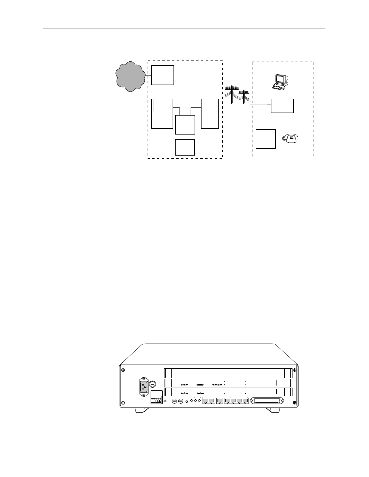
HotWire DSLAM System Description
Central Office (CO)
Network
Service
Provider
HotWire
8200
IPC
DSL
CARD
DSLAM
Legend: DSL - Digital Subscriber Line RTU - Remote Termination Unit
MDF - Main Distribution Frame POTS - Plain Old Telephone Service
IPC - Interworking Packet Concentrator
* Optional
HotWire DSLAM Components
Ethernet
*CO
POTS
Splitter
CO
Switch
MDF
POTS/DSL
Customer Premises (CP)
Data
Interface
RTU
POTS
*CP
Voice
Interface
POTS
Splitter
97-15674-01
The HotWire DSLAM system consists of the following components:
HotWire DSLAM chassis
There are two types of chassis:
— Each HotWire 8600 DSLAM is an independent, standalone system. The
stackable design provides for up to six systems to share management
access through a single Management Communications Controller (MCC)
card, which in turn, allows an additional slot for a DSL card in each of up
to five additional systems.
In a stacked configuration, the first, or base chassis, must contain an
MCC card in Slot 1. In addition to the MCC card, the base chassis can
house up to two DSL cards. Each additional chassis in the stack houses
up to three DSL cards.
OK
Alrm
TestTXRX
AC
INPUT
AC
T5A
250V
RTN48V
AAB B
48VDC CLASS 2 OR
LIMITED PWR SOURCE
SYSTEM
SYSTEM
SYSTEM
DC FUSES
T4A, MIN. 48V
A
OK
OK
B
ETHERNET
Alrm
TestTXRX
ETHERNET
Alrm
TestTXRX
ETHERNET
FAN
5
46
.
3
.
2
ALM
.
1
.
STACK
POSITION
DC PWR
A
B
Col1234
DSL PORT
Col1234
DSL PORT
Col
MANAGEMENT
IN
OUT SERIAL
MCC 1
LAN/WAN SLOT
2
3
8546
RADSL
8546
RADSL
8000
MCC
LINE
3
2
1
1-2
November 1997
97-15350-01
8000-A2-GB20-20
Page 13
HotWire DSLAM System Description
For more information about the HotWire 8600 DSLAM chassis, see the
HotWire 8600 Digital Subscriber Line Access Multiplexer (DSLAM)
Installation Guide
.
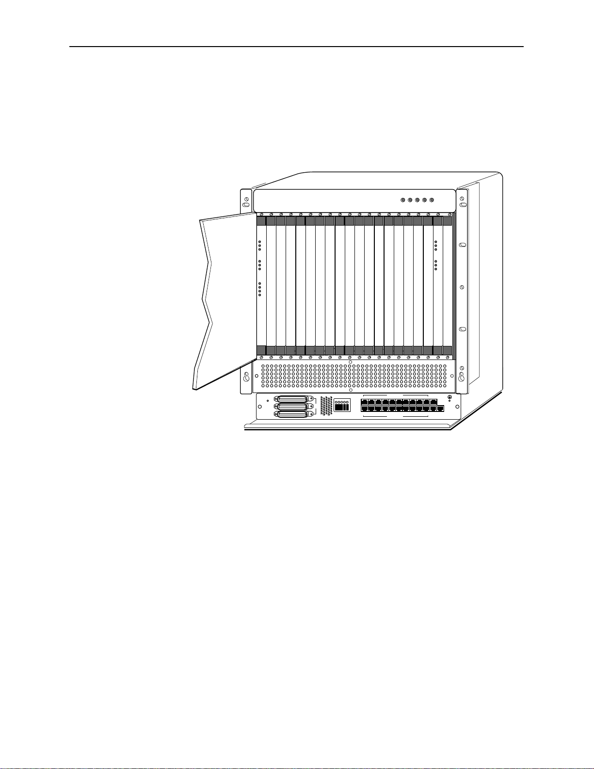
— The HotWire 8800 DSLAM chassis is a 20-slot chassis designed to
house up to 18 DSL cards and one MCC card. (The remaining slot is
reserved for future use.)
ALARMS
POWER
Major MinorFanBA
SYSTEM
ETHERNET
DSL PORT
RADSL
OK
Alm
Test
TX
RX
Coll
1
2
3
4
SLOTS 13-18
SLOTS 13-18
SLOTS 7-12
SLOTS 1 - 6
-48V INPUT
LINES
-48V (A)
-48V (B)
RET (A)
RET (B)
FR GND
LAN/WAN SLOT
101214
8
6
4
2
11
7
35
1
9
LAN/WAN SLOT
13 15
SYSTEM
OK
Alm
Test
ETHERNET
TX
RX
Coll
MCC
MGT
16
20
18
SERIAL
ALARM
19
17
MGT
10BT
For more information about the HotWire 8800 DSLAM chassis, see the
HotWire 8800 Digital Subscriber Line Access Multiplexer (DSLAM)
Installation Guide
.
One Management Communications Controller (MCC) card
The chassis requires one MCC card, which is a processor card that
administers and provides diagnostic connectivity to the DSL cards. It acts as
a mid-level manager and works in conjunction with a Simple Network
Management Protocol (SNMP) system, such as Paradyne’s DCE Manager
for HP OpenView, via its LAN port. It gathers operational status for each of
the DSL cards and responds to the SNMP requests. It also has a serial port
for a local user interface to the DSLAM.
97-15280
8000-A2-GB20-20
At least one Digital Subscriber Line (DSL) card
The chassis requires at least one DSL card, which is a circuit card that
contains four Rate Adaptive Digital Subscriber Line (RADSL) modem ports,
an Ethernet interface to the ISP, and a processor/packet forwarder. The
processor/packet forwarder controls the modems and forwards the packet
traffic via the Ethernet and DSL interfaces. When the 8600 DSLAM chassis is
fully populated, it provides a total of 68 RADSL modem ports. When the
8800 DSLAM chassis is fully populated, it provides a total of 72 RADSL
modem ports.
November 1997
1-3
Page 14

HotWire DSLAM System Description
Features
The HotWire DSLAM system provides the following features:
High speed Internet or Intranet access.
Rate Adaptive Digital Subscriber Line ports.
Subscriber authentication and security access and permission features that
prevent users from accessing unauthorized services.
Status polling, alarm indicators and logging, diagnostics, and performance
capabilities.
Primary network management support via SNMP agent for monitoring and
traps; telnet for configuration and diagnostics.
Dynamic IP addressing, allowing Network Service Providers the ability to
reuse IP addresses.
Levels of Access
There are two levels of diagnostic/administrative access in the HotWire DSLAM
system:
Administrator
The Administrator has complete read/write access to the DSLAM system.
With Administrator permission, you can set specific parameters and variables
to configure cards, ports, interfaces, user accounts, next hop routes, and
SNMP security .
Operator
The Operator has read-only access. With Operator permission, you can view
card status, physical layer status, interfaces, and Internet Protocol (IP)
routes, and run non-disruptive tests.
HotWire DSLAM Software Functionality
Depending upon your system access, you can:
Configure the system,
Monitor the system, and/or
Run applications and diagnostic tests to troubleshoot the network
1-4
November 1997
8000-A2-GB20-20
Page 15

Configuring the System
The HotWire DSLAM software provides configuration submenu options to:
Configure the MCC card, DSL cards, and RTU connectivity
Configure the interfaces and ports
Set up user accounts
Upload or download a copy of a card’s configuration data to or from a Trivial
Download a new version of the DSLAM software
Define an IP routing table
Define and enable filters to prevent unauthorized network access
Configure the SNMP agent to send traps to a specific SNMP NMS manager
HotWire DSLAM System Description
File Transfer Protocol (TFTP) server
NOTE:
You must have administrator permission to configure the system. For more
information about configuring the system, see Chapters 4, 5, and 6.
Monitoring the System
The HotWire DSLAM software provides submenu options to monitor the activity
of the HotWire MCC and DSL cards. The monitoring screens allow you to:
List the status of active ports and interfaces in a card, as well as display
Display network protocol statistics, such as information about an application
Display information about the routing table and detailed information about
Display the current Address Resolution Protocol (ARP) table.
Display information about the configured IP router filters.
Use the monitoring screens to help you gather pertinent information and isolate
potential problem areas. You can monitor the system with either administrator or
operator permission. For more information about monitoring the system, see
Chapter 7,
statistics about other physical layers and interfaces.
program assigned to a specific socket number, UDP statistics, TCP data and
connection statistics, IP statistics, ICMP packet statistics, SNMP statistics
including SNMP authentication statistics, HDLC statistics, and PPP statistics.
each routing entry.
Monitoring the HotWire DSLAM
.
8000-A2-GB20-20
November 1997
1-5
Page 16

HotWire DSLAM System Description
Troubleshooting and Diagnostics
The HotWire DSLAM system provides diagnostic submenu options that:
Display selftest results for CPU, memories, and ports
Perform ping tests and display results
Show major and minor alarms
Display or clear system error logs
Enable or disable the A/B power supply alarm
Perform a trace route to an IP address to display a list of intermediate nodes
to the destination
Run a nondisruptive packet echo test over the DSL line to an RTU
NOTE:
You must have administrator permission to perform most of the
troubleshooting and diagnostic activities. However, you can run
non-disruptive tests as a user with operator permission. For more information
about troubleshooting and diagnostics, see Chapter 8,
T roubleshooting
Diagnostics and
.
1-6
November 1997
8000-A2-GB20-20
Page 17

HotWire Menus and Screens
Overview
The HotWire DSLAM has a menu- and screen-driven user interface system that
enables the user to configure and monitor the HotWire cards. This chapter
covers:
Menu and screen format
Commonly used navigation keys
2
Menu trees
— HotWire Chassis Main Menu
— HotWire – MCC Menu
— HotWire – DSL Menu
Logging in to the system
— Reviewing the Levels of Access
— Operator Login Screen
— Card Selection Screen
— Accessing the HotWire – MCC Menu
— Accessing the HotWire – DSL Menu
Exiting from the system
8000-A2-GB20-20
November 1997
2-1
Page 18

HotWire Menus and Screens
Menu and Screen Formats
The HotWire DSLAM uses an ASCII-based text format for its menus and screens.
This section describes the components of a typical HotWire menu and screen.
Components of a HotWire Menu
A typical HotWire menu format looks like this:
1
2
3
1. Menu Title is the top line of the menu window that displays the title of the
menu or submenu.
2. Menu List is the portion of the menu window that displays the list of menu
options. When selected, a menu option displays a submenu window or
screen.
3. Letter Navigation Keys are provided within a menu list. These keys provide
a convenient way (short cut) to select a menu item.
For example, from the HotWire – MCC menu illustrated above, you can
simply press the A key to select the Configuration menu item. The
Configuration menu appears. You can then press the G key to select the DSL
Cards menu item. This action displays the DSL Cards menu. (You can also
use the arrow keys on your keyboard to select a menu item. See
Used Navigation Keys
4. To back up one menu level, press Ctrl-z. To go to the Home screen, press
Ctrl-a.
on page 2-5 for more information.)
Commonly
2-2
November 1997
8000-A2-GB20-20
Page 19
Components of a HotWire Screen
A typical HotWire screen looks like this:
2
HotWire Menus and Screens
1
3
4
1. System Header Line is the top line of the screen. This line has three fields
that provide system login information.
— The first field displays the chassis name or the individual card name.
(Access the System Information screen by selecting the appropriate card
in the chassis and then follow this menu sequence:
→
Status
Card Info
.) If you do not define the system name, the DSLAM
Configuration→Card
user interface will display <no name>.
— The middle field displays the current login. This field will display either
L:<user_login> or R:<user_login> where L indicates a local login,
R indicates a remote login, and <user_login> is the login account of
the user currently accessing the system. For example, if a user with a
admin
login account called
logs into the system using the local console,
this field will display L:admin.
— The last field displays the previous remote or local login on what is
currently displayed in the middle field (i.e., the current login). If the
current login is local, the last field displays previous
R:<user_login>. If the current login is remote, the last field displays
previous L:<user_login>. L indicates a local login, R indicates a
remote login, and <user_login> is the login account of the user that
has accessed the system. For example, if a user with a login account
admin
called
logs into the system remotely via a telnet session, this field
will display R:admin. R displays only when a telnet session was active.
8000-A2-GB20-20
November 1997
2-3
Page 20

HotWire Menus and Screens
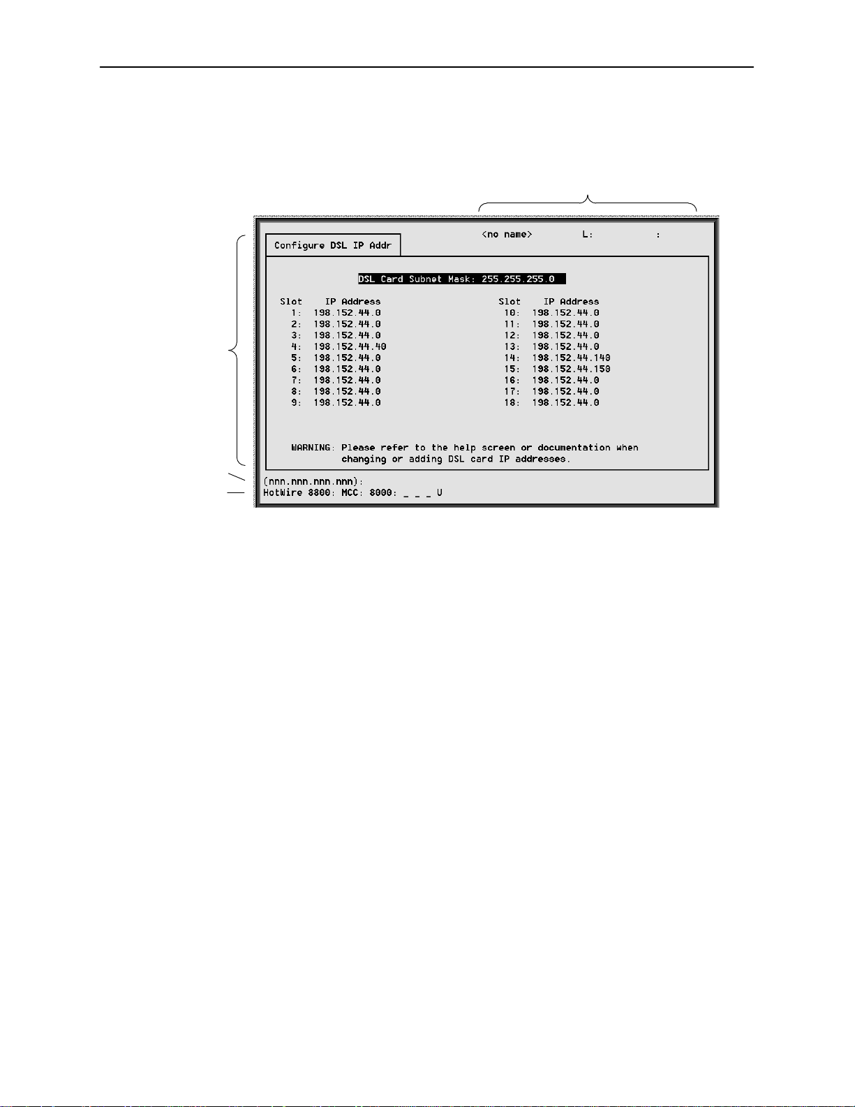
2. Display Area is the top portion of the screen on which pertinent DSLAM
3. Input Line is the area of the screen where you are prompted to enter values
4. Status Line is the last line on the screen. This line displays status
system information is displayed. This is also the portion of the screen on
which fields requiring input are displayed. However, you cannot enter values
for the fields in this portion of the screen. You must enter field values in the
Input Line at the bottom of the screen (see below).
for the specific field that is highlighted on the screen.
For example, in the Configure DSL IP Addr screen above, the DSL Card
Subnet Mask field is highlighted. If you want to change the subnet mask, you
must enter the new subnet mask at the (nnn.nnn.nnn.nnn): prompt at
the bottom of the screen.
information about the selected card.
For example, in the above illustration, the following line is displayed:
HotWire 8800: MCC: 8000: __ __ __ X
The first field indicates the chassis type. In this case, the system in use is the
HotWire 8800 DSLAM system. The second field indicates the card selected.
In this example, the MCC card is selected. The remaining fields indicate card
status information, such as whether or not an alarm is present and the status
of the Ethernet link. Similar information is displayed on the Card Selection
screen. For information about these fields, see
Card Selection Screen
on
page 2-14.
2-4
November 1997
8000-A2-GB20-20
Page 21

Commonly Used Navigation Keys
The following table lists the most commonly used navigation keys with their
definitions. These commands are used to move around the menus and screens.
For a complete list of keys, see Appendix D,
Keys Definition
Ctrl-a Moves Home or to the top of the menu.
Ctrl-k Moves up to the previous menu selection or entry field.
Ctrl-l Refreshes the screen.
Ctrl-p Moves back a field.
Ctrl-t Moves Home or to the top of the menu.
Ctrl-v Displays a pop-up list of all interfaces on the IP Network screen.
Displays a pop-up list of all accounts in system on the Configure
Accounts screen.
Ctrl-z Moves back one menu level or exits from screen.
HotWire Menus and Screens
Navigation Keys.
Up arrow Moves up to the previous menu selection or entry field.
Down arrow Moves down to the next menu choice or entry field.
Left arrow Moves left to the previous menu box or entry field.
Right arrow Moves right to the next menu box or entry field.
Enter or Return Accepts entry.
Tab Moves down or to the next selection.
? Displays Online help screens that correspond to the particular
menu or system screen displayed.
8000-A2-GB20-20
November 1997
2-5
Page 22

HotWire Menus and Screens
HotWire Menus: A Hierarchical View
This section describes the menu structure of the HotWire user interface.
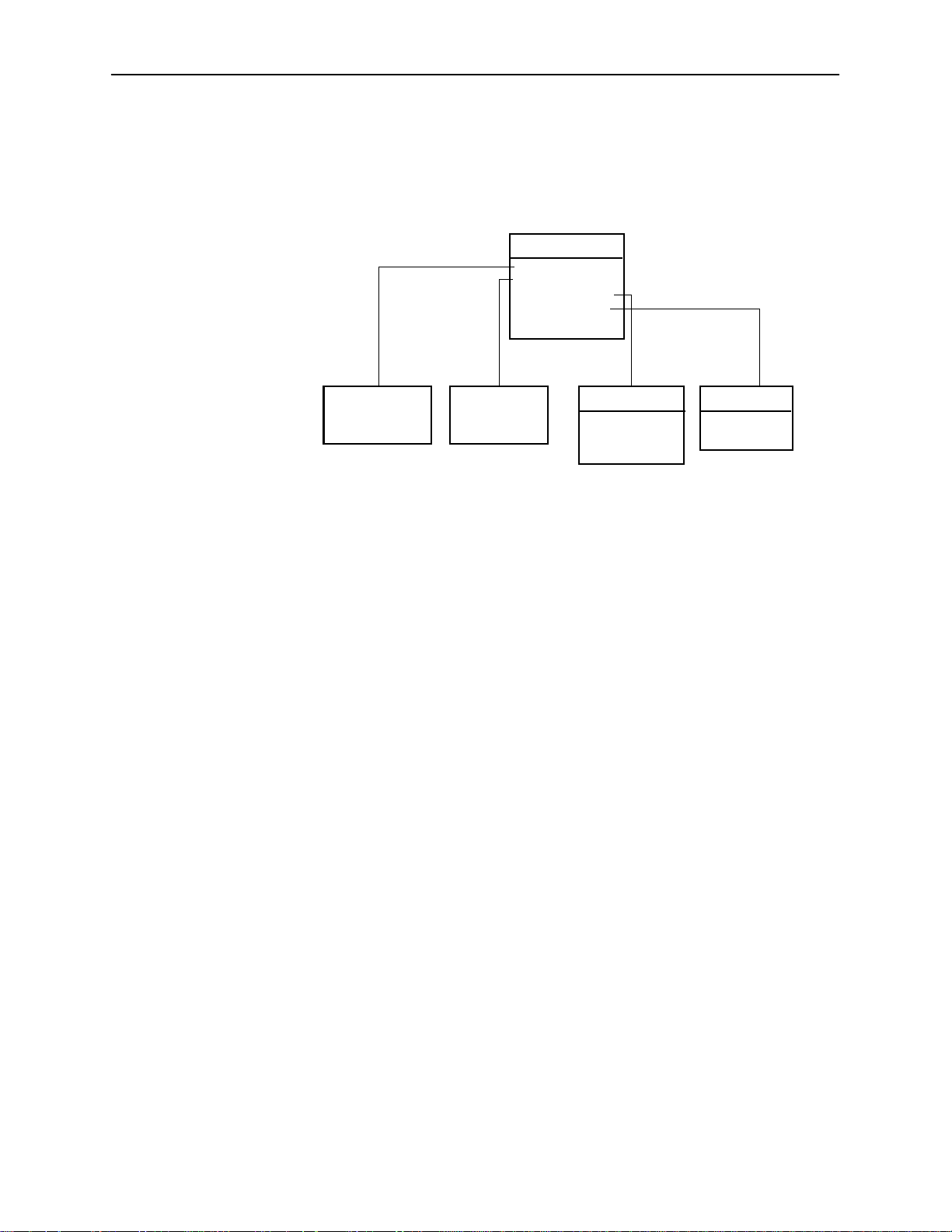
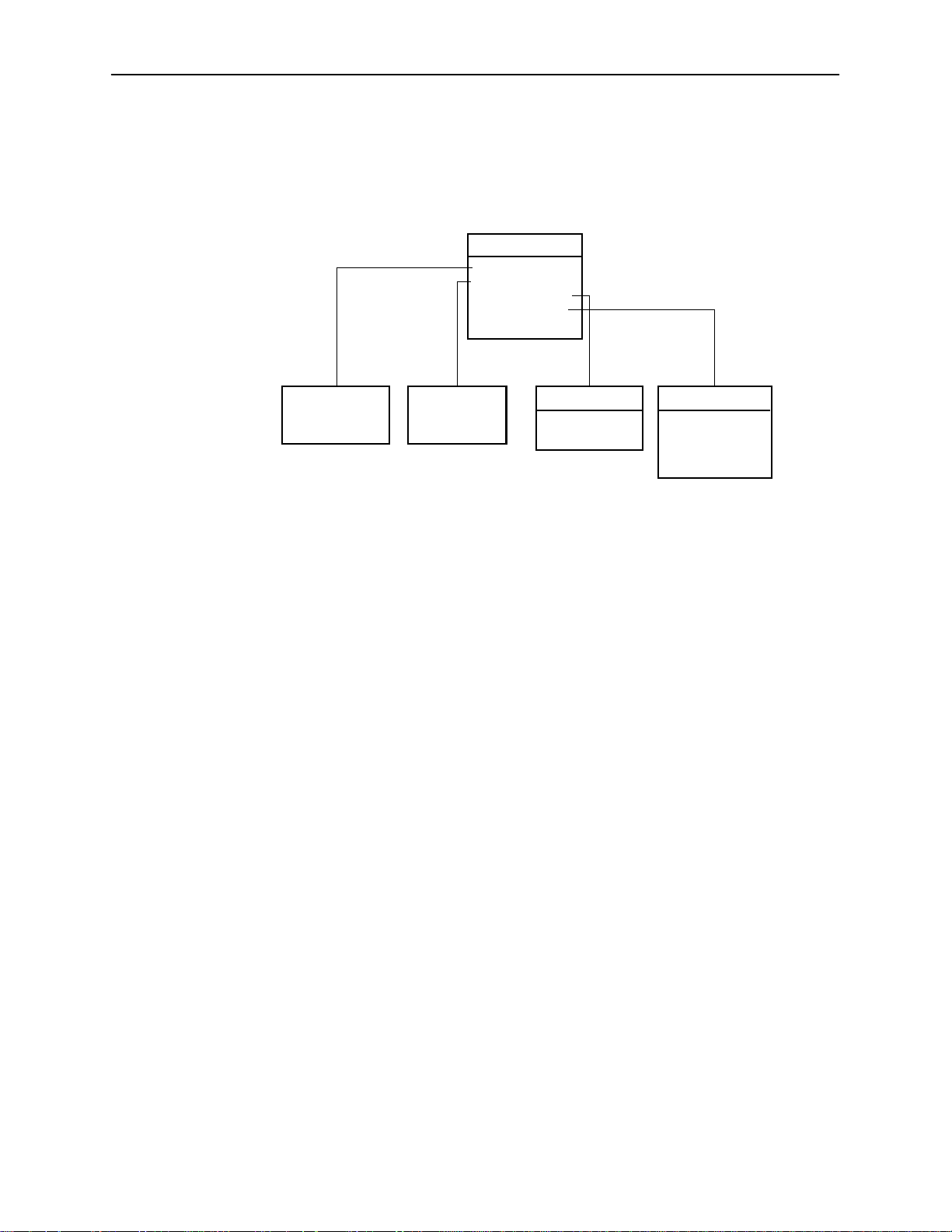
HotWire Chassis Main Menu
The following illustration shows the HotWire Chassis Main Menu.
HotWire Chassis
A. Chassis Info
B. Card Selection
C. Logout
97-15566
From the HotWire Chassis Main Menu, you can select:
A. Chassis Info to enter or display chassis information, such as the chassis
name, name of person responsible for the system, and physical location of
the chassis.
For more information, see
Additional Setup Instructions
in Chapter 3.
B. Card Selection to select a particular card in the chassis. This screen also
displays status information about all cards in the chassis. The card you select
determines which HotWire menu the system will display next (either the
HotWire – MCC menu or the HotWire – DSL menu).
For more information, see
C. Logout to exit from the current login session on the HotWire DSLAM.
For more information, see
Card Selection screen
Exiting From the System
on page 2-14.
on page 2-16.
2-6
November 1997
8000-A2-GB20-20
Page 23
HotWire – MCC Menu
1
After selecting the MCC card from the Card Selection screen, the DSLAM system
displays the HotWire – MCC Menu.
HotWire Menus and Screens
HotWire-MCC
A. Configuration*
B. Monitoring
C. Applications
D. Diagnostics
E. Exit
See
Configuration
Menu Below*
* The configuration menu item appears only if you have
administrator permission.
See
Monitoring
Menu Below
Applications
A. Ping
B. Trace Route
C. Telnet
Diagnostics
A. Selftest
B. Alarms
97-15557-0
From this menu, you can configure, monitor, run applications, and troubleshoot
the MCC card.
8000-A2-GB20-20
November 1997
2-7
Page 24

HotWire Menus and Screens
The following figure illustrates the complete Configuration menu hierarchy from
the HotWire – MCC menu.
NOTE:
The Configuration menu and its submenus appear only when logging in to
the system with a user account that has administrator permission.
Configuration
A. Card Status
B. Ports
C. Interfaces
D. Users
E. IP Router
F. SNMP
G.DSL Cards
(B) Ports
(A) Card Status
A. Card Info
B. DNS Setup
C.Time/Date
D.NVRAM Clear
E. NVRAM Cfg Loader
F. Card Reset
G.Download Code
(G) Download Code
A. Download Code
B. Apply Download
(C) Interfaces
A. General
B. IP Network
C. Control
(D) Users
A. Accounts
(E) IP Router
A. Static Routes
B. Martian Networks
C. IP Router Filters
D. ARP
E. Host T ab le
(F) SNMP
A. Security
B. Logical Entities
C. Logical Entities 2
D. Communities/Traps
(D) ARP
A. Parameters
B. Add Entry
C. Delete Entry
(G) DSL Cards
A. Set IP Address
B. Reset Slot
97-15558-01
2-8
November 1997
8000-A2-GB20-20
Page 25

HotWire Menus and Screens
1
The following figure illustrates the complete Monitoring menu hierarchy from the
HotWire – MCC menu.
Monitoring
A.Card Status
B.Physical Layer
C.Interfaces
D.Network Protocol
E.IP Router
(A) Card Status
A. Card Info
B. Login History
C. Syslog
(B) Physical Layer
A. Active List
B. Ether Statistics
C. HDLC Bus Stats
(C) Interfaces
A. Active List
B. Status
(D) Network Protocol
A. Socket Statistics
B. UDP Statistics
C. TCP Statistics
D. IP Statistics
E. ICMP Statistics
F. SNMP Statistics
G. HDLC Statistics
(E) IP Router
A. Routing Table
B. ARP Table
C. Filter Table
97-15559-0
8000-A2-GB20-20
November 1997
2-9
Page 26
HotWire Menus and Screens
HotWire – DSL Menu
After selecting a specific DSL card from the Card Selection screen, the DSLAM
system displays the HotWire – DSL Menu.
HotWire-DSL
A. Configuration*
B. Monitoring
C. Applications
D. Diagnostics
E. Exit
See
Configuration
Menu Below*
* The configuration menu item appears only if you have
admininstrator permission.
See
Monitoring
Menu Below
Applications
A. Ping
B. Trace Route
Diagnostics
A. Selftest
B. Alarms
C. Packet Echo
Test
97-15563-01
From this menu, you can configure, monitor, run applications, and troubleshoot a
specific DSL card.
2-10
November 1997
8000-A2-GB20-20
Page 27

HotWire Menus and Screens
1
The following figure illustrates the complete Configuration menu hierarchy from
the HotWire – DSL menu.
NOTE:
The Configuration menu and its submenus appear only when logging in to
the system with a user account that has administrator permission.
Configuration
A. Card Status
B. Ports
C. Interfaces
D. Users
E. IP Router
F. SNMP
G. DHCP Rela y
H. RTU Config
(B) Ports
A. Ethernet Port
B. DSL Ports
(A) Card Status
A. Card Info
B. DNS Setup
C.Time/Date
D.NVRAM Clear
E. NVRAM Cfg Loader
F. Card Reset
G.Download Code
(G) Download Code
A. Download Code
B. Apply Download
(C) Interfaces
A. General
B. IP Network
C Control
D. PPP*
*Not on Model 8540
(D) Users
A. Accounts
(E) IP Router
A. Static Routes
B. Martian Networks
C. IP Router Filters
D. ARP
E. Host T ab le
(F) SNMP
A. Security
B. Logical Entities
C. Communities
/Traps
(G) DHCP Relay
A. Domain Names
B. Servers 1-8
C. Servers 9-16
(D) ARP
A. Parameters
B. Add Entry
C. Delete Entry
97-15564-0
8000-A2-GB20-20
November 1997
2-11
Page 28

HotWire Menus and Screens
The following figure illustrates the complete Monitoring menu hierarchy from the
HotWire – DSL menu.
Monitoring
A.Card Status
B.Physical Layer
C.Interfaces
D.Network Protocol
E.IP Router
F. RTU Information
(A) Card/CPE Status
A. Card Info
B. Login History
C. Syslog
(B) Physical Layer
A. Active List
B. Ether Statistics
C. HDLC Bus Stats
D. DSL Link Perf
E. DSL Perf Stats
F. DSL Error Stats
G. DSL Xmit Stats
*Not on Model 8540
(C) Interfaces
A. Active List
B. Status
(D) Network Protocol
A. Socket Statistics
B. UDP Statistics
C. TCP Statistics
D. IP Statistics
E. ICMP Statistics
F. SNMP Statistics
G. HDLC Statistics
H. PPP Stats*
(E) IP Router
A. Routing Table
B. ARP Table
C. Filter Table
(H) PPP Stats
A. General
B. LCP Stats
C. IPCP Stats
(F) RTU config
A. RTU Information
97-15565-01
Logging in to the System (After the System Has Been
Configured)
NOTE:
When you power on the system for the first time, the system displays the
Who Am I screen. This screen can be accessed only from the local console.
Accessing the System for the First
2-12
For information about this screen, see
in Chapter 3.
Time
This section describes how to log in to the HotWire DSLAM system after the
system has been configured for the first time.
November 1997
8000-A2-GB20-20
Page 29
Reviewing the Levels of Access
There are two levels of privileges on the HotWire DSLAM system. Your user
accounts can be configured with a user name, password, and privilege of:
Administrator, giving you access to all of the features of the system including
configuration options, or
Operator, giving you read-only access.
The default access is no login and password with administrator status. To provide
login security to the DSLAM, user accounts must be configured. See
Configuration Users Screens
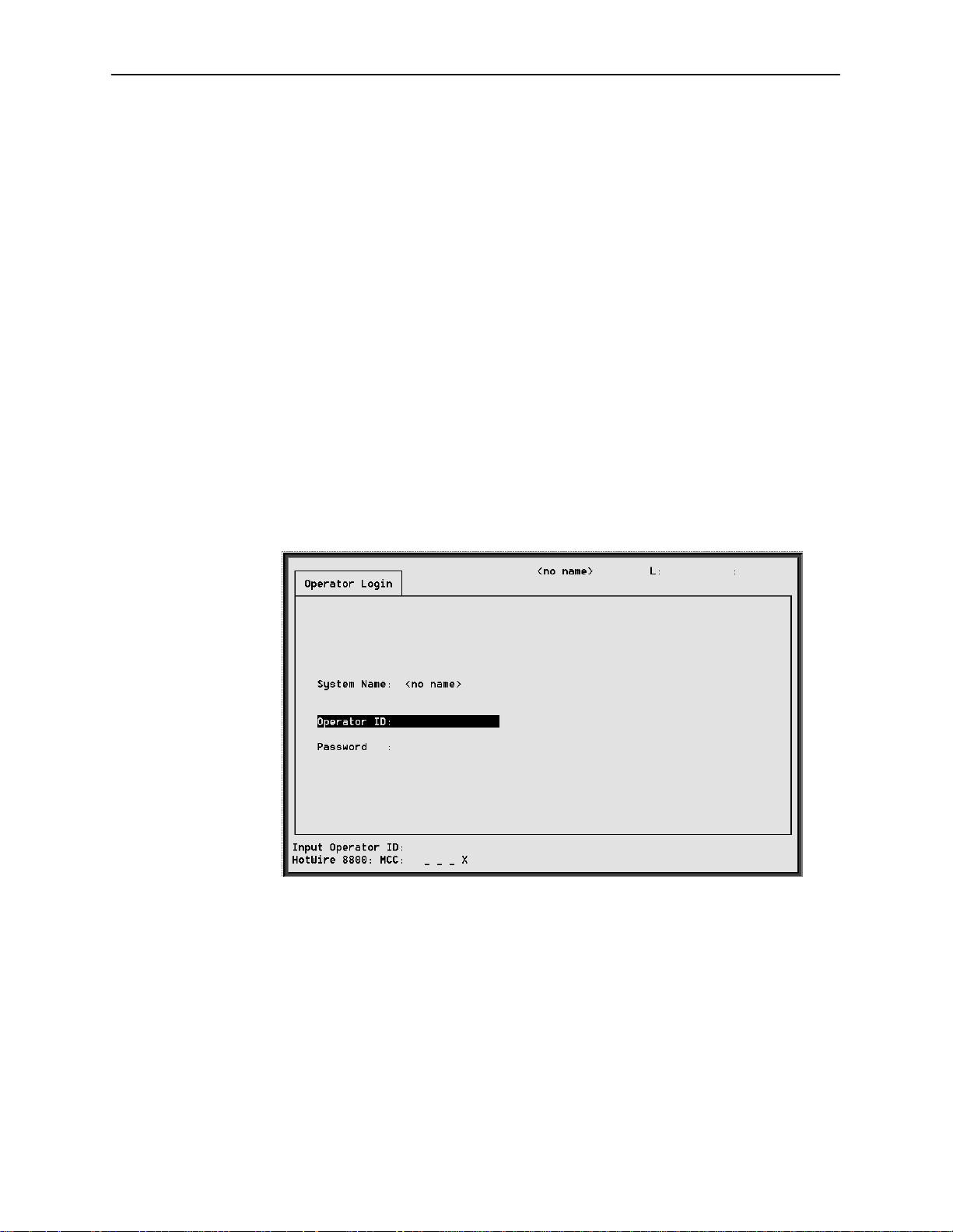
Operator Login Screen
You can log into the HotWire DSLAM system using either a local VT100compatible terminal or a remote Telnet connection. However, the HotWire DSLAM
system accepts only one login session at a time.
At the Operator Login screen, enter your login ID and password.
HotWire Menus and Screens
MCC
in Chapter 5.
8000-A2-GB20-20
NOTE:
The login ID and password are case sensitive; that is, the system recognizes
both upper- and lower-case letters. For example, if you enter your user name
and password information in upper case letters and your assigned user name
and password are in upper- and lower-case letters, the system will not let you
log in.
After entering your login ID and password, the system displays the HotWire
Chassis Main Menu.
November 1997
2-13
Page 30
HotWire Menus and Screens
3
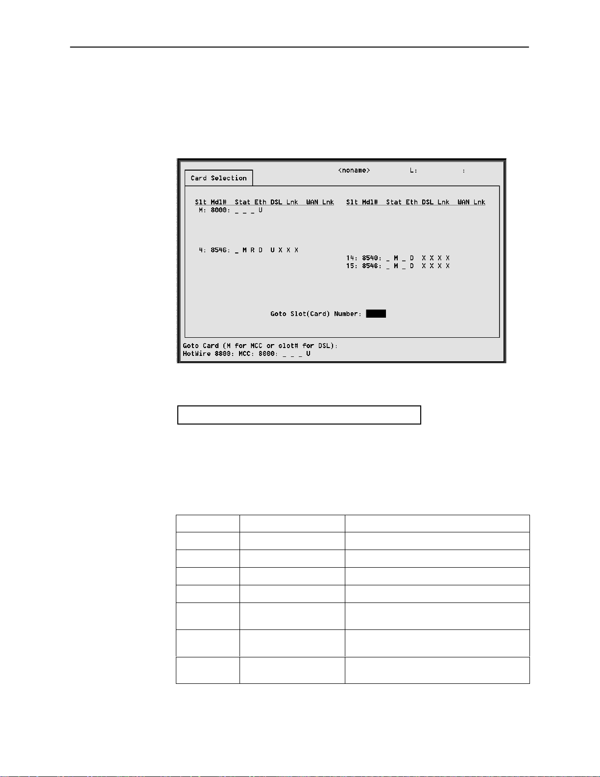
Card Selection Screen
From the HotWire Chassis Main Menu, select Card Selection to display the status
of any of the 18 cards present in the chassis by type and slot number. The Card
Selection screen also displays general and interface status for each card.
The following figure illustrates the positional display of the card selection screen:
<card name> T M R e d1 d2 d3 d4 w1 w2 w3 w4
97-1569
On the chassis display, the following information is shown.
NOTE:
If an option is not active, an underscore is shown in its place.
Position
1 T (Test mode) Card currently in test mode
2 M (Major alarm) Major alarm present on card
3 R (Minor alarm) Minor alarm present on card
4 e (Ethernet) Status of Ethernet link (U=UP, D=Down, or
5 d1 (DSL)# Status of DSL card Port 1 (U=UP, D=Down,
6 d2 (DSL)# Status of DSL card Port 2 (U=UP, D=Down,
Display Description
<card type> MCC
X=Disabled)
or X=Disabled, or H=Handshaking)
or X=Disabled, or H=Handshaking)
2-14
November 1997
8000-A2-GB20-20
Page 31

HotWire Menus and Screens
Position DescriptionDisplay
7 d3 (DSL)# Status of DSL card Port 3 (U=UP, D=Down,
or X=Disabled, or H=Handshaking)
8 d4 (DSL)# Status of DSL card Port 4 (U=UP, D=Down,
or X=Disabled, or H=Handshaking)
9 w1 (WAN)*# Status of WAN link (U=Up, D=Down,
L=Loopback)
– w2 (WAN)*# Status of WAN link Port 2 (U=Up, D=Down,
L=Loopback)
– w3 (WAN)*# Status of WAN link Port 3 (U=Up, D=Down,
L=Loopback)
– w4 (WAN)*# Status of WAN link Port 4 (U=Up, D=Down,
L=Loopback)
* Not applicable for 8540 or 8546 DSLAM RADSL circuit cards of MCC cards.
# Not used for MCC cards.
If an option is not active, an underscore is shown in its place.
Also on this screen, there is a prompt used to select a specific card in the DSLAM
chassis. When a DSL slot number is entered, you are telneted (in the
background) to the card you selected.
NOTE:
When you select MCC on this screen, there is no telnet session involved. The
login screens and the top level menu reside on the MCC.
For more information about the status displayed on this screen, such as major
and minor alarms, see
Accessing the HotWire – MCC Menu
Procedure
To access the HotWire – MCC menu:
1. From the HotWire Chassis Main Menu, select B for Card Selection.
The Card Selection screen appears.
2. At the Goto Card (MCC or DSLnn): prompt, enter MCC or M.
The HotWire – MCC menu appears.
Troubleshooting
in Chapter 8.
8000-A2-GB20-20
November 1997
2-15
Page 32

HotWire Menus and Screens
Accessing the HotWire – DSL Menu and Selecting a Specific DSL Card
Procedure
To access the HotWire – DSL menu:
1. From the HotWire Chassis Main Menu, select Card Selection.
The Card Selection screen appears.
2. Verify that the DSL card you want to access appears on the Card Selection
screen. (See
3. At the Goto Card (MCC or DSLnn): prompt, enter DSL and the number
of the slot. Then, press Return. For example, if you want to configure the DSL
card in Slot 13, enter DSL13 or 13.
The HotWire – DSL menu appears.
Card Selection Screen
on page 2-14 for more information.)
Exiting From the System
You can manually log out of the system or, after five minutes of inactivity, the
system will automatically log you out.
Manually Logging Off
Procedure
To exit from the HotWire DSLAM system:
1. Return to the HotWire Chassis Main Menu by selecting Exit from either the
HotWire – MCC menu or the HotWire – DSL menu.
The HotWire Chassis Main Menu appears.
2. From the HotWire Chassis Main Menu, select Logout.
The system exits from the current login session on the HotWire DSLAM.
Automatically Logging Off
The DSLAM system has an automatic timeout feature that logs you out of the
system after five minutes of inactivity. You will need to log back in to continue
your work.
To log back in, press Return to display the Operator Login screen and log in.
2-16
November 1997
8000-A2-GB20-20
Page 33

Initial Setup Instructions
Overview
This chapter provides instructions on how to access the system for the first time
and perform initial setup instructions.
NOTE:
It is highly recommended that you read the
8546 DSL Cards Network Configuration Guide
configure the system. The Network Configuration Guide provides worksheets
to help you plan and configure your network.
3
HotWire DSLAM for 8540 and
before you attempt to
Accessing the System for the First Time
When you power on the HotWire DSLAM for the first time, the system displays
the Who Am I screen on the console terminal. On this screen, you must set the
management IP address and subnet mask for the MCC card. Follow the
instructions in the following section,
Subnet Mask on the MCC
.
Setting the Management IP Address and
Setting the Management IP Address and Subnet
Mask on the MCC
After powering on the system for the first time, set the management IP address
and subnet mask of the MCC card. This is a mandatory step and must be
completed before proceeding to Chapter 4,
Configuring the HotWire DSLAM
.
8000-A2-GB20-20
November 1997
3-1
Page 34

Initial Setup Instructions
Procedur e
To set the management IP address and subnet mask from the console terminal:
1. Power up the chassis.
After the self-test completes, the Who Am I screen appears.
2. From the Who Am I screen, enter the management domain IP address of the
MCC card and press the Return key. For example, if the IP address of the
MCC card is 198.152.110.1, type this value at the (nnn.nnn.nnn.nnn):
prompt on the Input Line at the bottom of the screen.
The system automatically calculates the subnet mask based on the IP
address you enter.
3-2
November 1997
8000-A2-GB20-20
Page 35

Initial Setup Instructions
3. Do one of the following at the (nnn.nnn.nnn.nnn): prompt:
— To accept the subnet mask, press Return.
— To enter a different subnet mask, enter a new subnet mask and press
Return.
The system highlights the OK to restart?: prompt.
4. Type y at the yes/no: prompt to restart the card or n to decline the restart.
If you type y, the card restarts. The system displays the HotWire Chassis
Main Menu.
NOTE:
At this point, the MCC card can accept a Telnet session to be used for
remote configuration.
Additional Setup Instructions
This section describes additional setup instructions you should perform. On the
Chassis Information screen, you can enter pertinent chassis information, such as
the chassis name, name of person responsible for the system, and physical
location of the chassis.
8000-A2-GB20-20
November 1997
3-3
Page 36

Initial Setup Instructions
Chassis Information Screen
Procedure
1. Choose Chassis Info from the HotWire Chassis Main Menu to enter or
display chassis configuration information.
The following table describes the information you should enter on the
Chassis Information screen. This information is used in the general section of
the SNMP MIB II.
What’s Next?
Field
Chassis Name 16 alphanumeric characters Name for the equipment
Chassis Contact 32 alphanumeric characters Name and phone number of
Chassis Location 16 alphanumeric characters Physical location of the
Bay Number 16 alphanumeric characters Floor and/or bay number of the
Chassis Number 16 alphanumeric characters Chassis serial number (located
2. When you have made the appropriate changes to the screen, a message
Configuration has been modified. Save (yes/no)? appears.
Enter yes to save changes and press Return to go back to the HotWire
Chassis Main Menu.
Input Description
individual responsible for the
equipment
equipment
equipment
on the lower right side of
chassis)
3-4
Now you are ready to configure your HotWire DSLAM. Refer to Chapter 4,
Configuring the HotWire DSLAM,
mandatory minimum configurations, and Chapter 5,
and Chapter 6,
when customizing your application.
After you have configured your system, you can monitor and troubleshoot
potential problems on the system. Refer to Chapter 7,
DSLAM
, and Chapter 8,
DSL Card Configuration
Diagnostics and Troubleshooting
November 1997
for instructions on how to configure the
MCC Card Configuration,
, for additional configuration instructions
Monitoring the HotWire
, for more information.
8000-A2-GB20-20
Page 37

Configuring the HotWire DSLAM
Overview
The HotWire DSLAM enables you to configure and manage the HotWire MCC
and DSL cards. This chapter describes the basic card configuration instructions.
Port Naming Convention
The following is the naming convention used for the HotWire DSLAM interfaces:
4
NOTE:
Interfaces are sometimes referred to as ports. The term
usually is reserved for referring to the physical layer attributes of an interface.
e1a — Interface name of the DSLAM system 10BaseT interface on the MCC
and DSL cards.
s1b — Interface name of the MCC and DSL card’s interface to the DSLAM
system backplane bus.
s1c, s1d, s1e, and s1f — Interface names of the four DSL ports on a DSL
card.
NOTE:
These names are used throughout the remainder of this guide to reference
the HotWire DSLAM interfaces. These are also the names used in the
HotWire DSLAM software when configuring the HotWire DSLAM system.
ports
, however,
8000-A2-GB20-20
November 1997
4-1
Page 38

Configuring the HotWire DSLAM
Configuring MCC Cards, DSL Cards, and RTUs
Use the procedures in the following order to configure the MCC and DSL cards
for the basic setup for terminal management and user data connectivity.
NOTE:
It is assumed that you have read the
Cards Network Configuration Guide
management domain IP addresses for all devices (MCC, DSL, and RTUs).
For your convenience, Appendix A of the
contains worksheets to record your configuration settings.
The following tables list the basic steps you need to configure the MCC cards,
DSL cards, and RTUs.
For the Management Domain,
perform task . . .
HotWire DSLAM for 8540 and 8546 DSL
and have assigned service and
Network Configuration Guide
On the . . . See . . .
1. Configure time and date. MCC
2. Assign the IP address to the
backplane on the MCC card.
3. Assign the IP addresses to the
DSL cards.
4. Create SNMP Community
Strings and Authentication
Failure Trap.
5. Create default route. MCC
6. Reset the MCC card. MCC
7. Select a DSL card to configure. DSL
8. Configure 5446 RTU IP host
address for the 8546 DSL card.
(Not applicable to 8540 DSL
card.)
MCC
MCC
MCC
DSL
Setting Time and Date Screen,
page 4-6.
Assigning IP Addresses to the
Backplane on the MCC Card,
page 4-7.
Assigning IP Addresses to the DSL
Cards on the MCC Card
page 4-8.
Creating SNMP Community
Strings and Authentication Failure
, page 4-9.
T rap
Creating the Default Route
page 4-10.
Resetting the MCC Card,
page 4-1 1.
Selecting a DSL Card to
Configure
Configuring 5446 RTU IP Host
Addresses on the 8546 DSL Card,
page 4-12.
, page 4-1 1.
,
,
4-2
November 1997
8000-A2-GB20-20
Page 39

For each Service Domain,
perform task . . .
Configuring the HotWire DSLAM
On the . . . See . . .
1. Configure a static route to the
NMS.
2. Assign IP addresses to the DSL
card LAN.
3. Reset the DSL card. DSL
4. Configure static routes to end
users on each DSL card.
5. Create DHCP Relay Agent. DSL
6. Create default route or source
route on DSL.
DSL
DSL
DSL
DSL
Configuring a Static Route to the
Network Management System on
each DSL Card
, page 4-13.
Assigning IP Addresses to the DSL
Card LAN
Resetting the DSL Card
page 4-15.
, page 4-14.
,
Configuring Static Routes to End
Users on each DSL Card
page 4-16.
Creating DHCP Relay Agent
page 4-17.
,
,
Creating Default Route or Source
Route on the DSL
, page 4-18.
8000-A2-GB20-20
November 1997
4-3
Page 40

Configuring the HotWire DSLAM
1
The following illustrates the management domain components that must be
configured and examples of the various naming conventions.
MANAGEMENT DOMAIN
DCE Manager
Server
10BT
DCE Manager
Router
b1: 135.1.3.254/
255.255.255.0
b2: 135.1.2.1/
255.255.255.0
Port Names
Task 3
* Only the 5446 RTU requires
an IP address in the
management domain
IP Address
e1a: 135.1.2.2/
255.255.255.0
MCC Card
s1b: 135.1.3.1/
255.255.255.0
System Backplane
s1b: 135.1.3.2/
255.255.255.0
DSL Card
IP Interface
DSLAM
s1c
s1d
s1e
s1f
DSL
DSL
DSL
DSL
RTU*
a: 135.1.3.3/
255.255.255.255
Task 2
RTU*
a: 135.1.3.4/
255.255.255.255
RTU
RTU
Task 8
Task 8
97-15561-0
4-4
November 1997
8000-A2-GB20-20
Page 41

Configuring the HotWire DSLAM
The following illustrates the service domain components that must be configured
and examples of the various naming conventions.
SERVICE DOMAIN
ISP Router
a: 155.1.2.1/
255.255.255.0
b1: 155.1.3.1/24
b16: 170.1.3.1/
255.255.255.0
* Only the 5446 RTU requires IP
addresses in the service domain
.
.
.
Tasks 2, 4 & 6
MCC Card
System Backplane
DSL Card
IP Interface
155.1.3.2/
e1a:
156.1.3.2/
.
.
.
170.1.3.2/
255.255.255.0
DSLAM
s1c
s1d
s1e
s1f
DSL
DSL
DSL
DSL
RTU*
b1: 155.1.3.3/
b2: 156.1.3.3/
b3: 157.1.3.3/
b4: 158.1.3.3/
255.255.255.0
RTU*
b1: 159.1.3.3/
b2: 160.1.3.3/
b3: 161.1.3.3/
b4: 162.1.3.3/
255.255.255.0
RTU
RTU
10BT
10BT
97-15562-01
8000-A2-GB20-20
November 1997
4-5
Page 42

Configuring the HotWire DSLAM
Setting Time and Date Screen
When you select Time/Date from the Card Status menu, the Time/Date screen is
displayed. From this screen, you can configure the local time and date on the
card.
Procedure
To set the time and date on the MCC card:
1. Select Card Selection (B) from the HotWire Chassis Main Menu.
2. At the Goto Card (MCC or DSLnn): prompt, enter MCC or M.
3. Select
Configuration→Card Status→Time/Date
(A-A-C).
4. Enter values for the following fields and press Return after each entry:
Field
Local Time/Date Current local time and date.
Client Network Time
Protocol (NTP) Mode
NTP Server* IP address of the NTP
Synchronized(hrs) How often the system
* While this field is optional, it is recommended that a value be entered to ensure the
time of the DSLAM stays in synch with “real time.”
Description Input
hh.mm (am
mm/dd/yy
General time protocol
(Broadcast) or specific time
protocol with address
(Unicast).
server.
should go out looking for the
time and date to
synchronize the system
time and date.
Broadcast or Unicast
(Default = broadcast)
nnn.nnn.nnn.nnn
1–24
or pm
format
)
format
NOTE:
At system boot time, the time on the DSL card automatically syncs with
the MCC card. Therefore, it is usually not necessary to use this screen on
the DSL. If there are active DHCP-leased routes on the card, changing
the local time is not recommended.
4-6
5. Press Ctrl-z to return to the
November 1997
Configuration→Card Status
menu.
8000-A2-GB20-20
Page 43

Assigning IP Addresses to the Backplane on the MCC Card
Use this procedure to create a separate and distinct network or subnetwork for
the 8546 DSL cards and 5446 RTUs.
Procedure
To assign IP addresss to the backplane:
Configuring the HotWire DSLAM
1. Select
Configuration→Interfaces→IP Network
(A-C-B).
2. Enter values for the following basic fields and press Return after each entry:
Field
IP Interface Name of the interface. s1b (backplane)
Base IP Addr IP address of the
Base Subnet Mask Associated subnet mask of
Peer IP Address IP address used to indicate
Route to Peer Routing method to use to get
* Enter the network/subnetwork portion of the Base IP address, with 0 for the
host portion so that the Peer is the entire subnet.
Description Input
nnn.nnn.nnn.nnn
management domain.
nnn.nnn.nnn.nnn
the base IP address.
nnn.nnn.nnn.nnn
directly connected systems.
Net
to peer (i.e., host or net).
format
format
format *
In addition, the following fields appear on the screen. These fields can be
used to customize your application.
Field
Description Input
8000-A2-GB20-20
Input Filter Prevents packets from
entering the DSL card
through a specified interface.
Output Filter Prevents packets from going
out of the DSL card through a
specified interface.
3. Press Ctrl-z to return to the
November 1997
Configuration→Interfaces
Blank to disable.
Blank to disable.
menu.
4-7
Page 44

Configuring the HotWire DSLAM
Assigning IP Addresses to the DSL Cards on the MCC Card
Use this procedure to define addresses within the management domain. These
are automatically assigned to the DSL cards when they are inserted in the
chassis.
Procedure
To assign IP addresses to the DSL cards:
1. Select
Configuration→DSL Cards→Set IP Address
(A-G-A)
.
2. Enter values for the following fields and press Return after each entry:
Field
DSL Card Subnet Mask Subnet mask for the
IP Address (for each DSL card) Management domain
Description Input
nnn.nnn.nnn.nnn
backplane(s1b)
management subnet.
IP address for each
DSL card in the
system.
format
nnn.nnn.nnn.nnn
format. (Subnet is
predetermined – you
can enter the host
number.)
NOTE:
You must have assigned IP addresses to the backplane on the IP
Network screen for s1b before performing this procedure.
3. Press Ctrl-z to return to the
Configuration→DSL Cards
menu.
4-8
November 1997
8000-A2-GB20-20
Page 45

Configuring the HotWire DSLAM
Creating SNMP Community Strings and Authentication Failure Trap
Use this procedure to configure SNMP community strings and enable the
Authentication Failure trap mechanism. For additional security, ensure that
source validation is enabled. (See Appendix C,
Features.
)
Checklist for Setting Up SNMP
Procedur e
To create SNMP community strings and authentication failure trap:
1. Select
Configuration→SNMP→Communities/Traps
(A-F-D)
.
2. Enter values for the following fields and press Return after each entry:
Field
Authentication Failure Trap Determines whether to
Community Name SNMP community
Access Permission that is
IP address and port NMS system host IP
Input Number Number of port. Default = 162
3. Confirm the save and press Ctrl-z to return to the
Description Input
Enable/Disable
send a trap when a
SNMP request
community string does
not match or when the
password for a telnet
session is incorrect.
Up to four unique
string name.
granted for each
community .
address
community names per
screen
RO = Read Only
RW = Read/Write
NA = No Access
nnn.nnn.nnn.nnn
format
Configuration→SNMP
menu.
8000-A2-GB20-20
November 1997
4-9
Page 46

Configuring the HotWire DSLAM
Creating the Default Route
Use this procedure to create the default route to the management domain next
hop router. This default route will be used to forward management domain traffic
from the MCC card.
Procedure
To create the default route:
1. Select
Configuration→IP Router→ Static_Routes
(A-E-A).
2. Press Return on the Item 0 field to add a new record.
3. Enter values for the following fields and press Return after each entry:
Field
Host/Net Destination of the route.
Subnet Mask Associated subnet mask
Next Hop IP address of the next hop
Pref (Preference) Measure of how preferable
Description Input
0.0.0.0
default route
nnn.nnn.nnn.nnn
for the specified
destination IP address.
nnn.nnn.nnn.nnn
device for the specified
destination.
1
one route is to another, if
you have two routes going
to the same destination.
(The lower the number, the
more preferable the route.)
This route is compared to
other routes for the same
destination address.
to indicate the
format
format
4-10
4. Confirm the save and press Ctrl-z to return to the
menu.
November 1997
Configuration→IP Router
8000-A2-GB20-20
Page 47

Resetting the MCC Card
After configuring the MCC card, reset the MCC card to install the configuration
settings.
Procedure
To reset the HotWire Chassis:
Configuring the HotWire DSLAM
1. Select
2. Enter yes (y) to verify MCC reset.
Configuration→Card Status→Card Reset
NOTE:
When you enter yes, all data connectivity is interrupted.
3. Wait for the MCC card to reboot.
4. Press Return.
5. The Operator Login screen is displayed.
6. Enter login information.
Selecting a DSL Card to Configure
All DSL cards that are present in the chassis and have had backplane addresses
assigned to them should appear on the Card Status screen. However, if one or
more do not appear, go to the MCC card, select
→
Cards
Reset Slot
Procedure
To select a specific DSL card to configure:
1. From the HotWire Chassis Main Menu, select Card Selection (B).
(A-A-F).
Configuration→DSL
and reset the DSL card.
8000-A2-GB20-20
nn
2. Enter DSL
configure, and press Return.
The HotWire DSL menu is displayed.
3. Select Configuration and press Return.
The Configuration Menu is displayed.
or nn, where nn is the number of the DSL card you want to
November 1997
4-11
Page 48

Configuring the HotWire DSLAM
Configuring 5446 RTU IP Host Addresses on the 8546 DSL Card
Use this procedure to assign an IP address within the management subnet to
each 5446 RTU interoperating with an 8546 DSL card.
Procedure
To configure IP host addresses on the DSL card:
1. Select
Configuration→Interfaces→IP Network
(A-C-B)
.
2. Enter values for the following basic fields and press Return after each entry:
Field
IP Interface Name of the interface. s1c (8546 DSL interface)
Peer IP Address IP address associated with
Route to Peer Routing method to use to get
* The subnet mask can be changed for the corresponding 5446 RTU. Refer to
Appendix F,
5446 RTU Setup.
Description Input
nnn.nnn.nnn.nnn
the other end of the link; i.e.,
the 5446 RTU.
Host
to peer (i.e., host or net).
format *
NOTE:
The DSL interface is “unnumbered,” meaning it requires no IP address.
(This field is read only.)
The following fields also appear on the screen. These fields can be used to
customize your application.
Field
Description Input
4-12
Input Filter Prevents packets from
entering the DSL card
through a specified interface.
Output Filter Prevents packets from going
out of the DSL card through a
specified interface.
Blank to disable.
Blank to disable.
3. Repeat the above procedure for interfaces s1d, s1e, and s1f (8546 DSL
Ports 2, 3, and 4, respectively).
4. Press Ctrl-z to return to the
November 1997
Configuration→Interfaces
menu.
8000-A2-GB20-20
Page 49

Configuring a Static Route to an NMS on each DSL Card
Use this procedure to enable the management traffic from the 8546 DSL cards or
5446 RTUs to be routed back through the MCC.
Procedure
To configure a static route to an NMS on each DSL card:
Configuring the HotWire DSLAM
1. Select
Configuration→IP Router→Static_Routes
(A-E-A)
.
2. Press Return on the Item 0 field to add a new record.
3. Enter values for the following fields and press Return after each entry:
Field
Host/Net Destination of the route to
Subnet Mask Associated subnet mask
Next Hop IP address of the next hop
Pref (Preference) Measure of how preferable
Description Input
0.0.0.0
the NMS.
for the specified
destination IP address to
the NMS.
device for the specified
destination to the NMS.
one route is to another, if
you have two routes going
to the same destination.
(The lower the number, the
more preferable the route.)
This route is compared to
other routes for the same
destination address.
default route
nnn.nnn.nnn.nnn
nnn.nnn.nnn.nnn
1
to indicate the
format
format
8000-A2-GB20-20
4. Confirm the save and press Ctrl-z to return to the
menu.
November 1997
Configuration→IP Router
4-13
Page 50

Configuring the HotWire DSLAM
Assigning IP Addresses to the DSL Card LAN
Use this procedure to give DSL cards a LAN Interface IP address in each
Network Service Provider (NSP) domain supported by those cards.
Procedure
To assign IP addresses to the DSL Card LAN:
1. Select
Configuration→Interfaces→IP Network
(A-C-B).
2. Enter values for the following fields and press Return after each entry:
Field
IP Interface Name of the interface.
IP Address (for
each 8540 and
8546 DSL card)
Subnet Mask Associated subnet mask for
Route to Peer
(Field does not
appear on
Model 8540.)
* Enter the network/subnetwork portion of the Base IP address, with 0 for the
host portion so that the Peer is the entire subnet.
e1a
and
Description Input
e1a
IP address for each DSL card
in the system. This address
must be different that the
management domain IP
address.
the specified destination IP
address.
Routing method used to get
to peer (i.e., host or net).
nnn.nnn.nnn.nnn
(Subnet is predetermined –
you can enter the host
number.)
nnn.nnn.nnn.nnn
Net
(Ethernet port)
format.
format
In addition, the following fields also appear on the screen. These fields can
be used to customize your application.
4-14
Field
Input Filter Prevents packets from
Output Filter Prevents packets from going
3. Press Ctrl-z to return to the
Description Input
entering the DSL card
through a specified interface.
out of the DSL card through a
specified interface.
Configuration→Interfaces
November 1997
Blank to disable.
Blank to disable.
menu.
8000-A2-GB20-20
Page 51

Resetting the DSL Card
After configuring all of the service domain IP addresses on a DSL card (IP
address has been added or changed), reset the card to enable the new
configuration changes.
Procedur e
To reset the DSL Card:
Configuring the HotWire DSLAM
1. Select
2. Enter DSL
configured.
3. Enter Y at the prompt to confirm.
Configuration→Card Status→Card Reset
nn
, where nn is the slot number for the DSL card you just
(A-A-F).
NOTE:
When you enter Y, all data connectivity is interrupted.
4. If you have entered yes, verify that the LEDs on the DSL card go through
the reset sequence once, and then a second time after approximately
10 seconds (BOOTP).
8000-A2-GB20-20
November 1997
4-15
Page 52

Configuring the HotWire DSLAM
Configuring Static Routes to End Users on each DSL Card
Use this procedure to enable the management traffic from the 8546 DSL cards to
the 5446 RTU and attached end-user systems. Use SNMP or the IP Injection Tool
to download the needed enterprise MIBs and to configure static routes and
service domain routes to end users attached to each 5446 RTU. Refer to
Appendix F,
5446 RTU Setup.
NOTE:
Each time you create a static route for an end-user system behind an RTU,
you should also create a corresponding source-based input filter rule. See
Chapter 5,
IP Filtering
IP Address Allocation,
, of the
HotWire DSLAM for 8540 and 8546 DSL Cards Network
Configuration Guide
.
Chapter 6
Procedur e
To configure a static route to End Users:
, IP Routing, and
Chapter 7,
1. Select
Configuration→IP Router→Static_Routes
(A-E-A)
.
2. Press Return on the Item 0 field to add a new record.
3. Enter values for the following fields and press Return after each entry:
Field
Host/Net Destination of the route.
Subnet Mask Associated subnet mask
Next Hop (on Model
8546)
Next Hop (on Model
8540)
Pref (Preference) Measure of how preferable
S/D (Source/Destination) Source or destination route
Description Input
0.0.0.0
default route
nnn.nnn.nnn.nnn
for the specified
destination IP address.
IP address of the next hop
device for the specified
destination.
DSL port name for next
hop.
one route is to another, if
you have two routes going
to the same destination.
type.
On Model 8540, subnet
mask must be
255.255.255.255.
nnn.nnn.nnn.nnn
Port name s1c, s1d, s1e,
or s1f.
The lower the number, the
more preferable the route.
Default = Dst
to indicate the
format
format
4-16
PA (Proxy ARP) Router answers ARP
requests intended for
another machine.
4. Confirm the save and press Ctrl-z to return to the
menu.
November 1997
Default = No
Configuration→IP Router
8000-A2-GB20-20
Page 53

Configuring DHCP Relay Agent (dynamic addressing)
Use this procedure to provide dynamic Service Domain IP address allocation to
the end-user systems attached to the DSL RTUs.
Procedure
To configure relay agent:
1. Make certain that the Gateway address used in relaying DHCP requests is
e1a
configured as an
address (A-C-B).
Configuring the HotWire DSLAM
2. Select
Configuration→DHCP Relay→ Domain Names
(A-G-A)
.
3. Enter values for the following field and press Return after each entry:
Field
Domain Names ISP domain names. 32 maximum characters.
Description Input
NOTE:
Unless your client supports the domain names field, you will not be able
to have service selection. By default, each port can be assigned one
service provider.
The Interface IP address is read only and is required to key in the
corresponding domain name.
4. Select
Configuration→DHCP Relay→ Servers 1–8 or 9–16
5. Enter values for the following field and press Return after each entry:
Field
DHCP Server DHCP server IP address.
Authen Server (optional) Authentication server IP
RADIUS Secret
(optional)
Authen Type Type of authentication you
Authentication Wait TIme
(optional)
Number of Authentication
attempts
Dynamic access control
security
Port (1–4) Default DHCP
Domain Index
Description Input
nnn.nnn.nnn.nnn
nnn.nnn.nnn.nnn
address for this domain.
RADIUS encryption value. Up to 16 numeric
characters.
N = none (No
want performed.
Authentication time out. Default = 5 seconds.
Authentication attempts. Default = 2 seconds.
Security control flag. E = Enable
Which domain’s DHCP
service will be used.
authentication to be
performed.)
R = RADIUS (Forward a
message to a RADIUS
server.)
T = XTACACS (Forward a
message to a XT ACACS
server.)
D = Disable.
0 = no default.
(A-G-B or C)
.
format.
format.
8000-A2-GB20-20
November 1997
4-17
Page 54

Configuring the HotWire DSLAM
Creating Default Route or Source Route on the DSL
Use this procedure to create a default route or source route for each DSL card
(upstream direction). You can create up to 16 default or source routes per DSL
card.
Procedure
To create default routes or source routes on the DSL:
1. Select
Configuration→IP Router→Static_Routes
(A-E-A).
2. Press Return on the Item 0 field to add a new record.
3. Enter values for the following fields and press Return after each entry.
Field
Host/Net Destination of the route.
Subnet Mask Associated subnet mask
Next Hop IP address of the next hop
Pref (Preference) Measure of how preferable
S/D (Source/Destination) Source or destination route
Description Input
0.0.0.0
default route
nnn.nnn.nnn.nnn
for the specified
destination IP address.
nnn.nnn.nnn.nnn
device for the specified
destination.
1
one route is to another, if
you have two routes going
to the same destination.
(The lower the number, the
more preferable the route.)
This route is compared to
other routes for the same
destination address.
Default = Dst
type.
to indicate the
format
format
4-18
PA (Proxy ARP) Router answers ARP
requests intended for
another machine.
4. Confirm the save and press Ctrl-z to return to the
menu.
November 1997
Default = No
Configuration→IP Router
8000-A2-GB20-20
Page 55

MCC Card Configuration
Overview
This chapter describes the configuration options on the MCC card. Use these
options to customize your applications.
MCC Configuration Card Status Screens
Use the system information submenu of the Card Status screens to configure
basic MCC card-level information.
5
8000-A2-GB20-20
NOTE:
Only a user who logs onto the HotWire DSLAM with Administrative
permission can configure the MCC card.
November 1997
5-1
Page 56

MCC Card Configuration
Procedur e
To configure card information, DNS setup, time/date, clear NVRAM, upload or
download configuration set, download new firmware, or reset card:
1. Follow this menu sequence:
Configuration→Card Status
(A-A)
2. The Card Status menu appears. Enter the desired value on each selected
screen and field as shown in Table 5-1 and press Return.
Table 5-1. Card Status Menu Options (1 of 3)
Card Info (System Information) A-A-A
Gives the user the ability to configure basic card-level information.
System Name – 16 alphanumeric characters. Name assigned to the card.
System Contact – 32 alphanumeric characters. Name or number of party responsible
for card.
System Location – 16 alphanumeric characters. Location assigned to the system.
Router ID – (This field is read only.) Diagnostic Domain IP address assigned to card.
Router Subnet Mask – (This field is read only .)
Local Control T erminal Port Mode – Standard/Extended (Default = Standard).
Standard is for USA keyboards; Extended is for European keyboards.
Remote Control Terminal Port Mode – Standard/Extended (Default = Standard).
Standard is for USA keyboards; Extended is for European keyboards.
T elnet daemon tcp port – 0–65536 (Default = 23). If you change this field, you need to
do a card reset.
Alarm on loss of Redundant Power – Enter Y if carrier has redundant power and you
want local and remote indications of the loss of one power source.
nnn.nnn.nnn.nnn
format.
DNS Setup (Configure DNS) A-A-B
Gives the user the ability to configure the access to DNS servers from which name to IP
address translation requests are made.
DNS Servers – Three entry fields in
Name System Server address.
Default Domain Name – 40 characters. Domain used for queries that are not fully
qualified. For example, if the default domain name = paradyne.com and a telnet is
attempted to reach a system called gemini, the card would query the DNS server for
gemini.paradyne.com.
Time to wait for response (secs) – 1– 15 seconds (Default = 5). Enter the time to wait
for a response.
Number of times to retry server – 1–3 times (Default = 2). Enter the number of times
to retry the server.
nnn.nnn.nnn.nnn
format. Enter the primary Domain
5-2
November 1997
8000-A2-GB20-20
Page 57

MCC Card Configuration
Table 5-1. Card Status Menu Options (2 of 3)
Time/Date A-A-C
Gives the user the ability to configure the local time and date on the DSL card with
network time and to synchronize the DSLAM’s clock via a Network Time Protocol (NTP)
server.
hh.mm
Local Time/Date – Enter the time in
mm/dd/yy
Client NTP Mode – Broadcast/Unicast (Default = Broadcast). Select the Client Network
Time Protocol Mode.
NTP Server –
Synchronized(hrs) – 1–24 (Default = 1). Enter the hours between synchronization.
NVRAM Clear Screen (Clear NVRAM) A-A-D
Gives the user the ability to clear out the Non-Volatile RAM (NVRAM) in order to reuse
the card or to reconfigure the current card.
NVRAM Config Loader A-A-E
Gives the user the ability to upload or download a copy of the card’s binary
configuration data to or from a Trivial File T ransfer Protocol (TFTP) server.
Configuration File Name – The file name may be a regular path name expression of
directory names separated by a forward slash (/) ending with the file name. The total
path name length must be less than 40 characters. If the TFTP server is hosted by a
DOS machine, then directory and file names must follow the 8.3 naming convention
imposed by DOS.
DOS Machine
If your server is hosted by a DOS machine, you must name the file to be uploaded
using the DOS convention eight-character length. The system will automatically
upload the configuration file and create directories and file names as needed.
UNIX Machine
If your server is hosted by a UNIX machine, the configuration file you name will not
be created on the UNIX system by the TFTP server. It is critical that you work with
your system administrator to plan the naming conventions for directories, filenames,
and permissions so that anyone using the system has read and write permissions.
(This is a UNIX system security feature.)
TFTP Server IP Address –
TFTP Transfer Direction – Upload/Download (Default = Upload). Select Upload to
store a copy of the card’s configuration on the server . Select Download to have the file
server send a copy of the stored configuration file to the card.
Start Transfer – Yes/No (Default = No).
format.
nnn.nnn.nnn.nnn
CAUTION: If you select yes on this screen, you will permanently remove most of
the configuration information you have stored on this card and all IP
addresses and routing tables will have to be re-entered. The system will
perform a reset and return to the factory configuration.
NOTE: This must be done before you can upload files to a UNIX server.
format. Enter the NTP Server IP address.
nnn.nnn.nnn.nnn
format (am or pm). Enter the date in
format.
8000-A2-GB20-20
Packets Sent – Number of packets sent in download.
Bytes Sent – Number of bytes sent in download.
Bytes Received – Number of bytes received in download.
Transfer Status – Status of the upload or download transfer.
NOTE: After a download, the card must be reset for the new configuration to take
effect.
November 1997
5-3
Page 58

MCC Card Configuration
Table 5-1. Card Status Menu Options (3 of 3)
Card Reset (Reset System) A-A-F
Gives the user the ability to reset the card. This resets all counters and if a new
configuration or software version has been downloaded, the new code will then become
active.
Reset Card – Enter Yes to reset card.
NOTE: This action disrupts the data flow for at least 10 seconds.
Download Code (Download Code and Apply Download) A-A-G
Gives the user the ability to download a new version of code and apply the downloaded
code. For further information on this feature, see Appendix C,
Apply Download.
Download Code A
This screen is similar to the NVRAM Config Loader screen.
Image File Name – The file name may be a regular pathname expression of directory
names separated by a forward slash (/) ending with the file name. The total pathname
length must be less than 40 characters. If the TFTP server is hosted by a DOS
machine, then directory and file names must follow the 8.3 naming convention imposed
by DOS.
TFTP Server IP Address –
Start Transfer – Yes/No (Default = No).
Packets Sent – Number of packets sent in download.
Packets Received – Number of packets received in download.
Bytes Sent – Number of bytes sent in download.
Bytes Received – Number of bytes received in download.
Transfer Status – Status of the download transfer.
Once the download is complete, press Ctrl-z to exit back to the Download Code
submenu and select Apply Download.
nnn.nnn.nnn.nnn
format.
Download Code and
5-4
Apply Download B
This selection applies the downloaded code and drops all connections by performing a
device reset. This screen is used to overlay the previously downloaded image for the
card. If you select yes at the Reset System prompt, the system goes through a system
restart and interrupts service on the card. For further information on this feature, see
Appendix C,
NOTE: If you have not previously downloaded code, then you will not be able to
Download Code and Apply Download.
access this selection.
November 1997
8000-A2-GB20-20
Page 59

MCC Configuration Ports Screens
(Reserved for Future Use)
NOTE:
There are no configurable ports on the MCC at this time.
MCC Configuration Interfaces Screens
Use the system information submenu of the Interfaces screens to configure basic
interface information.
Procedure
To configure general interfaces, IP networks, and control interfaces:
1. Follow this menu sequence:
Configuration→Interfaces
MCC Card Configuration
(A-C)
2. The Interfaces menu appears. Enter the desired value on each selected
screen and field as shown in Table 5-2 and press Return.
Table 5-2. Interfaces Menu Options (1 of 2)
General (Interfaces) A-C-A
Gives the user the ability to configure basic information about a given interface.
Interface Name – s1b = backplane that connects all the cards, e1a = Ethernet port.
T ype – Static.
Protocol – Type of protocol for an interface.
Port List – Name of the port associated with this interface.
MTU (max) (Maximum Transmission Unit) – 64–64000 (Default = 1500). For the
Model 8540, the MTU (max) is 1500, with the range being 61–1500.
NOTE: The above MTU values are the only values you may enter. Do not change
the MTU of s1b from the default of 1500. Make certain that if you change
from the default value, the numbers are appropriate to your network. Do a
card reset or reset the interface.
8000-A2-GB20-20
November 1997
5-5
Page 60

MCC Card Configuration
Table 5-2. Interfaces Menu Options (2 of 2)
IP Network A-C-B
Gives the user the ability to configure up to 16 IP addresses for the LAN port. However,
under normal conditions, only one IP address in the management domain need be
assigned.
IP Interface – 15 characters. s1b = backplane that connects all cards; e1a = Ethernet
port.
Base IP Addr –
Base Subnet Mask –
IP Addr –
e1a is the IP interface name.
Subnet Mask –
appears if e1a is the IP interface name.
Input Filter – Optional.
Output Filter – Optional.
Peer IP Address –
Route to Peer – Net. Only appears if s1b is the interface name.
NOTE: If you have made any changes to this screen, you must do a card reset or
Control (Control Interface) A-C-C
Gives the user the ability to restart, stop, and monitor (up, down, or testing) the current
state of an interface.
This screen is populated depending on your entry in the Command and Interface Name
fields. For example, if you select Monitor mode and enter s1b for the Interface name,
the following information is displayed: Type, State, Link Protocol, IP State, Uptime,
Inactive, Connect Time, Port, Local IP Addr, and Peer IP Addr.
nnn.nnn.nnn.nnn
nnn.nnn.nnn.nnn
nnn.nnn.nnn.nnn
nnn.nnn.nnn.nnn
nnn.nnn.nnn.nnn
restart the appropriate interface (e1a or s1b). For changes to the s1b
interface, the peer IP address for each of the DSL ports (s1c, s1d, s1e, s1f)
on each DSL card must be changed and saved. In addition, the DSL card
must be reset.
format.
format.
format. (You may enter up to 16 addresses.) Only appears if
format. (You may enter up to 16 addresses.) Only
format. Only appears if s1b is the interface name.
5-6
November 1997
8000-A2-GB20-20
Page 61

MCC Configuration Users Screens
Use the system information submenu of the Users screens to configure login
accounts for local terminal and telnet sessions.
Procedure
1. Follow this menu sequence:
Configuration→Users
2. The Users menu appears. Enter the desired value on each selected screen
and field as shown in Table 5-3 and press Return.
Table 5-3. Users Menu Options
Users (Configure Account) A-D-A
Gives the user the ability to add, edit, or delete a user from a system account and to edit
user passwords and privileges. Up to 10 active users can be supported.
User accounts provide security for the DSLAM by requiring that anyone who is trying to
log onto the system has a valid password to gain access. User accounts on the MCC
provide security to users accessing the system from the VT100-compatible terminal
interface and via Telnet over the management domain LAN.
If no accounts are set up, then no login or password is required to gain entry to the
system via the terminal interface or telnet.
It is recommended that user accounts also be set up for each DSL card, even if you do
not intend to telnet directly to the DSL cards, so that no unauthorized telnet sessions
can be made. Each card will support up to 10 user accounts with either Operator (read
only) or Administrator (read/write) permissions.
If you configure an account on the MCC card, you have privileges on both the MCC and
DSL cards.
If you configure an account on the DSL card, you only have privileges for that specific
DSL card and only via a Telnet session.
Action – Add/Edit/Delete.
Login ID – Enter your Login ID.
Password – Enter the password associated with the login ID.
Repeat Password – Re-enter the password.
Privilege – Operator/Administrator. Enter Operator for read-only access; enter
Administrator for complete system access.
NOTE: Use Ctrl-v to see a list of all user accounts at the Login ID prompt.
MCC Card Configuration
(A-D)
8000-A2-GB20-20
November 1997
5-7
Page 62

MCC Card Configuration
MCC Configuration IP Router Screens
Use the system information submenu of the IP Router screens to configure static
routes to protocols and filters.
Procedure
To configure static routes, martian networks, and IP router filters:
1. Follow this menu sequence:
Configuration→IP Router
2. The IP Router menu appears. Enter the desired value on each selected
screen and field as shown in Table 5-4 and press Return.
Table 5-4. IP Router Menu Options (1 of 4)
Static Routes A-E-A
Gives the user the ability to add or delete static routes in the system. You can add up to
32 static routes.
Item – Press Return on 0 field to add entry.
Host/Net –
dynamic routes.
Subnet Mask – Associated subnet mask for the specified destination IP address. This
field is read only for dynamic routes.
Next Hop –
Pref– Measure of how preferable one route is to another, if you have two routes going
to the same destination. (The lower the number, the more preferable.) This route is
compared to others for the same address. This field is read only for dynamic routes.
S/D (Source/Destination) – Source or destination IP address of the packet. This field is
read only for dynamic routes.
PA (Proxy ARP) – Router answers ARP requests intended for another machine. This
field is read only for dynamic routes.
NOTE: When you define a source route, the Proxy ARP field is no longer
Martian Networks A-E-B
nnn.nnn.nnn.nnn
nnn.nnn.nnn.nnn
selectable.
format or space to delete entry . This field is read only for
format. This field is read only for dynamic routes.
(A-E)
5-8
Gives the user the ability to enter addresses that the system recognizes as invalid.
Item – Press Return on 0 field to add entry.
Martian Net ID –
unwanted source.
Martian Net Mask –
NOTE: The system is shipped with default martian networks. It is recommended
nnn.nnn.nnn.nnn
nnn.nnn.nnn.nnn
that you do not remove entries. If you have made changes to this screen,
you must do a card reset.
November 1997
format or space to delete entry . Enter IP address of
format. Enter IP mask of unwanted source.
8000-A2-GB20-20
Page 63

MCC Card Configuration
Table 5-4. IP Router Menu Options (2 of 4)
Filter T able A-E-C
Displays an overview of the various filters that are in the system.
The FIlter Table screen displays the following information:
Line – Sequential number of line.
Filter Name – Name of the IP filter.
# of Static Rules – Number of static routes in filter.
# of Dynamic Rules – Number of dynamic routes in filters.
Reference Count – Number of active interfaces using the filter.
Default Action – Default action for the filter.
On the bottom of this screen, at the Goto Line Number (0 to Add, #to Edit,
-# to Delete) prompt:
Select 0 to add a new filter to existing filters.
Select # to edit existing filters.
Select -# to delete a filter.
The Add or Edit selection takes you to the IP Filter Configuration screen. When you exit
that screen, you return to the Filter Table screen.
8000-A2-GB20-20
November 1997
5-9
Page 64

MCC Card Configuration
Table 5-4. IP Router Menu Options (3 of 4)
IP Router Filters (IP Filter Configuration) A-E-C
Gives the user the ability to build name sets of filter rules. A filter is a rule (or set of
rules) that is applied to a specific interface to indicate whether a packet can be
forwarded or discarded. You can add, edit, or delete router filter rules within a named
set. View filter names by pressing Ctrl-v.
A filter works by successively applying the rules to the information obtained from the
packet header until a match is found. The filter then performs the action specified by the
rule on that packet, which can be forwarded, discarded, or both.
Rules apply to the source and destination ports going to the end-user system. You may
have up to 33 rules per filter, but the greater number of rules, the lesser the
performance of the router filter.
On the MCC card, a maximum of two filters can be configured.
For additional information on IP Router filters, see Chapter 7,
IP Filtering
DSLAM for 8540 and 8546 DSL Cards Network Configuration Guide
Action – Add/Delete/Edit.
Filter Name – Up to 16 characters (optional).
Default Filter Action – Discard (Packet)/Forward (Packet).
Rule # – Up to 33 rules can be configured for each filter. This number is automatically
assigned.
# of Rules – Number of rules that apply to this port.
Source Address –
Source Address Mask –
of 0.0.0.0, the system skips the source address comparison.
Source Port No – 0–65536 (Default = 0). If the source port number is 0, the system
filters ICMP packets in addition to the packet types defined in the rule.
Comparison T ype – Ignore – Do not do a comparison. To do a comparison on the port
number specified in the packet and the rule, specify one of the following: Ignore –
Ignore ports. EQ – Equal to, NEQ – Not Equal To, GT – Greater than, LT – Less than,
In_Range – Within the specified range, Out_Range – Outside of the specified range.
Destination Address –
Destination Address Mask –
subnet mask of 0.0.0.0, the system skips the destination address comparison.
Destination Port No – 0–65536 (Default = 0). If the source port number is 0, the
system filters ICMP packets in addition to the packet types defined in the rule.
Comparison T ype – Ignore – Ignore ports, EQ – Equal to, NEQ – Not Equal To,
GT – Greater than, L T – Less than, In_Range – Maximum source port,
Out_Range – Minimum source port.
Filter Action – Discard (Packet)/Forward (Packet).
Rule Type – Static/Dynamic (Default = Static).
Delete Rule – Yes/No.
Go to Rule Number – Default = 0.
nnn.nnn.nnn.nnn
nnn.nnn.nnn.nnn
nnn.nnn.nnn.nnn
format.
format. If you specify a source subnet mask
format.
nnn.nnn.nnn.nnn
format. If you specify a destination
.
, of the
HotWire
5-10
November 1997
8000-A2-GB20-20
Page 65

MCC Card Configuration
Table 5-4. IP Router Menu Options (4 of 4)
ARP (Parameters, Add Entry, and Delete Entry) A-E-D (A-E-A to A-E-C)
Select:
Parameters (A)
Gives the user the ability to configure general Address Resolution Protocol (ARP) cache
parameters.
Complete Entry Timeout (minutes) – 1–200,000 (Default = 20).
Incomplete Entry Timeout (minutes) – 1–200,000 (Default = 20).
NOTE: If you have made changes to this screen, you must do a card reset.
Add Entry (Add ARP Entry) (B)
Gives the user the ability to add entries into the ARP cache.
IP Address/Host Name –
MAC Address –
Trailers – Yes/No (Default = No).
Proxy – Yes/No (Default = No).
PERM – Yes/No (Default = No). If you select yes for Perm and no to proxy, the ARP
entry will be saved in NVRAM (up to 32 entries; 8 for the MCC). These are loaded
when the card reboots.
Add Entry? – Enter Yes to add an entry or exit.
Add Another Entry? – Enter Yes to add another entry.
xx-xx-xx-xx-xx-xx
nnn.nnn.nnn.nnn
format.
format.
Delete Entry (Delete ARP Entry) (C)
Gives the user the ability to delete entries line by line in the ARP cache. The screen
displays columns for Line, IP Address, Ethernet Address, Min, and Delete.
Select the line you want to delete, select Yes and press Return.
NOTE: For the Add and Delete ARP Entry screens, any information entered is not
Host Table (IP Host Table) A-E-E
Gives the user the ability to define mappings between IP addresses and host names.
The host table can be used to hold the host name to IP address translation for telnet
sessions out from the card. An alternative to populating this table is to define a DNS
server (see A-A-B).
Enter the IP Address and Host Name in
each entry.
NOTE: You have to confirm the save for any changes to take effect.
stored in the NV memory and will be lost when you reset the card.
nnn.nnn.nnn.nnn
format and press Return after
8000-A2-GB20-20
November 1997
5-11
Page 66

MCC Card Configuration
MCC Configuration SNMP Screens
Use the system information submenu of the SNMP screens to configure SNMP
security, logical entities, community names, and trap addresses.
" Procedure
To configure SNMP security, SNMP Logical entities, and SNMP
Communities/Traps:
1. Follow this menu sequence:
Configuration→SNMP
2. The SNMP appears. Enter the desired value on each selected screen and
field as shown in Table 5-5 and press Return.
Table 5-5. SNMP Menu Options (1 of 2)
Security (SNMP Security) A-F-A
Gives the user the ability to configure allowable NMS IP addresses and to configure
SNMP agent.
Although SNMP community strings (if they are changed from the defaults) provide a
measure of security for unauthorized managers, enabling IP address security and
entering the IP address of up to five authorized SNMP managers provides a much
higher level of security. When IP address security is enabled, the source address of any
SNMP message addressed to any of the card’s IP addresses (in either the management
or service domain) will be checked against the authorized list and will be dropped if
there is no match.
IP Address Security – Enable/Disable (Default = Disable).
H Enabling allows DSLAM to accept SNMP messages from SNMP managers whose
IP source addresses have been entered in the IP Address field.
NOTE: If enabled with no IP address specified or with all addresses set to No
H Disabling stops IP address checking and allows the card to respond to a SNMP
IP Address –
managers.
Access – ReadOnly(ro)/ReadWrite(rw)/NoAccess(na). Permission to be granted to
each NMS manager.
Logical Entities (SNMP Logical Entities) A-F-B
Access (NA) permission, then there is no SNMP connectivity to the MCC
card.
query from any source with a proper community string.
nnn.nnn.nnn.nnn
format. Enter up to five IP source addresses of NMS
(A-F)
5-12
This screen displays default system information contained in the logical table of the
Entity MIB. Only the Community Name fields can be edited; others are read only .
H I (Index) column shows the index number of DSL cards 1 through 18.
H T (Type) column shows “D” for DSL cards.
H Read Only Comm and Read Write Comm show the community strings of the
DSL cards present in that slot.
Logical Entities 2 (SNMP Logical Entities 2) A-F-C
Continuation of previous screen.
November 1997
8000-A2-GB20-20
Page 67

MCC Card Configuration
Table 5-5. SNMP Menu Options (2 of 2)
Communities/Traps (SNMP Communities/Traps) A-F-D
Gives the user the ability to enable the Authentication Failure Trap Mechanism, stores
SNMP Community string names for the DSL card, and stores NMS host IP addresses to
which the DSLAM sends trap messages.
It also lets the user configure four communities with three trap destinations each. This
can be for a total of up to 12 destinations.
Authentication Failure Trap – Enable to send a trap when a SNMP request community
string does not match or when the password for a Telnet session is incorrect.
Community Name – 32 characters, up to four unique entries per screen. Default
names are public (ro), mcc (rw), nms (rw), nms-2 (ro).
Access – ReadOnly(ro)/ReadWrite(rw)/NoAccess(na), up to four entries per screen.
IP Address –
Input Number (port) –
Send Traps – Set to E to Enable traps to be sent to this address. Set to D to disable.
nnn.nnn.nnn.nnn
nnn
format. Enter NMS system port number.
format. Enter NMS system host address.
8000-A2-GB20-20
November 1997
5-13
Page 68

MCC Card Configuration
MCC DSL Cards Screen
Use the system information submenu of the DSL Cards screen to set IP
addresses and reset the DSL cards.
Procedure
To Configure DSL IP addresses and Reset DSL Slot:
1. Follow this menu sequence:
Configuration→DSL Cards
2. The DSL Cards menu appears. Enter the desired value on each selected on
each selected screen and field as shown in Table 5-6 and press Return.
Table 5-6. DSL Options
Set IP Address (Configure DSL IP Addr) A-G-A
You must assign up to 18 IP addresses in the management domain, one for each slot in
the DSLAM that has a DSL card. These are addresses for the s1b backplane interface
on each DSL card and will be automatically assigned to the DSL card when it is inserted
in a slot. All IP addresses must be on the same Management Domain Subnet as the
MCC’s IP address (entered on the MCC’s IP Network screen A-C-B).
DSL Card Subnet Mask –
Slot – Slot number of the DSL card.
IP Address –
host number.)
NOTE: If you have made changes to this screen, you must do a card reset or
restart the s1b interface. Also, do not assign the same subnets as those
used for the e1a (Ethernet) service domains.
Reset Slot (Reset DSL Slot) A-G-B
nnn.nnn.nnn.nnn
nnn.nnn.nnn.nnn
(A-G)
format.
format. (Subnet is predetermined – you can enter the
5-14
Gives the user the ability to perform a reset of a DSL card in any DSLAM slot. This reset
should be performed if there is a card in a slot but it does not appear on the DSLAM
card selection screen. After entering the card number, selecting the command that will
be sent (ForceBootP or reset), and confirming the reset, the MCC sends a reset signal
via the backplane to the selected card.
Your choices on this screen allow you to ForceBootP (a nondisruptive reset), Reset (a
minor disruption of less than 30 seconds), or Clear NVRAM (resets card and restores
factory default settings).
DSL Card/Slot # – Slot number of the DSL card.
Command – ForceBootP/Reset. ForceBootP will only work for certain cards (e.g., with
T1 and E1 connections).
Clear NVRAM also – Yes/No.*
NOTE: If a DSL card has been reset but still does not appear on the screen, its
* If you select yes on this screen, you will permanently remove most of the configuration
information you have stored on this card and all IP addresses and routing tables will
have to be reentered. The system will perform a reset and return to the factory
settings.
configuration may have been corrupted and the card should be reset again,
this time answering yes at the Clear NVRAM prompt. If the card then
appears on the screen, it will have to be reconfigured. If the card does not
appear on the screen, it should probably be replaced.
November 1997
8000-A2-GB20-20
Page 69

DSL Card Configuration
Overview
This chapter describes the non-mandatory configuration options on the DSL card.
Use these options to customize your applications.
NOTE:
Certain parameters such as speeds are dependent on the settings on the
RTU Configuration screen. Go to
select your RTU type for each port before any additional configuration
activities.
Configuration→RTU Config
6
(A-H) and
DSL Configuration Card Status Screens
Use the system information submenu of the Card Status screens to configure
basic DSL card-level information.
8000-A2-GB20-20
November 1997
6-1
Page 70

DSL Card Configuration
Procedure
NOTE:
Only a user who logs on to the HotWire DSLAM with Administrative
permission can configure the DSL card.
To configure card information, DNS setup, time/date, clear NVRAM, upload or
download configuration set, download new firmware, or reset card:
1. Follow this menu sequence:
Configuration→Card Status
2. The Card Status menu appears. Enter the desired value on each selected
screen and field as shown in Table 6-1 and press Return.
Table 6-1. Card Status Options (1 of 4)
Card Info (System Information) A-A-A
Gives the user the ability to configure basic card-level information.
System Name – 16 alphanumeric characters. Name assigned to the card.
System Contact – 32 alphanumeric characters. Name or number of party responsible
for card.
System Location – 16 alphanumeric characters. Location assigned to the card.
Router ID –
address assigned to card by the MCC.
Router Subnet Mask –
Local Control T erminal Port Mode – Standard/Extended (Default = Standard).
Standard is for USA keyboards; Extended is for European keyboards.
Remote Control Terminal Port Mode – Standard/Extended (Default = Standard).
Standard is for USA keyboards; Extended is for European keyboards.
T elnet daemon tcp port – 0–65536 (Default = 23). If you change this field, you need to
do a card reset.
DNS Setup (Configure DNS) A-A-B
nnn.nnn.nnn.nnn
nnn.nnn.nnn.nnn
format. (This field is read only .) Diagnostic Domain IP
(A-A)
format. (This field is read only .)
6-2
Gives the user the ability to configure the access to DNS servers from which name to IP
address translation requests are made.
DNS Servers – Three entry fields in
Name System Server address.
Default Domain Name – 40 characters. Domain used for queries that are not fully
qualified. For example, if the default domain name = paradyne.com and a telnet is
attempted to reach a system called gemini, the card would query the DNS server for
gemini.paradyne.com.
Time to wait for response – 1–15 seconds (Default = 5). Enter the time to wait for a
response.
Number of times to retry server – 1–3 times (Default = 2). Enter the number of times
to retry the server.
November 1997
nnn.nnn.nnn.nnn
format. Enter the primary Domain
8000-A2-GB20-20
Page 71

DSL Card Configuration
Table 6-1. Card Status Options (2 of 4)
Time/Date A-A-C
Gives the user the ability to configure the local time and date on the DSL card with
network time and to synchronize the DSLAM’s clock via a Network Time Protocol (NTP)
server.
Local Time/Date – Enter the time in
mm/dd/yy
Client NTP Mode – Broadcast/Unicast (Default = Broadcast). Select the Client Network
Time Protocol (NTP) Mode.
NTP Server –
Synchronized(hrs) – 1–24 (Default = 1). Enter the hours between synchronization.
NVRAM Clear Screen (Clear NVRAM) A-A-D
Gives the user the ability to clear out the Non-Volatile RAM (NVRAM) in order to reuse
the card or to reconfigure the current card.
format.
nnn.nnn.nnn.nnn
NOTE: At system boot time, the time on the DSL cards automatically synchronizes
with the MCC card. Therefore it is usually not necessary to use this screen
on the DSL card.
CAUTION: If you select yes on this screen, you will permanently remove most of
the configuration information you have stored on this card and all IP
addresses and routing tables will have to be re-entered. The system will
perform a reset and return to the factory configuration.
hh.mm
format (am or pm). Enter the date in
format. Enter the NTP Server IP address.
8000-A2-GB20-20
November 1997
6-3
Page 72

DSL Card Configuration
Table 6-1. Card Status Options (3 of 4)
NVRAM Config Loader A-A-E
Gives the user the ability to upload or download a copy of the card’s binary
configuration data to or from a Trivial File T ransfer Protocol (TFTP) server.
Configuration File Name –The file name may be a regular path name expression of
directory names separated by a forward slash (/) ending with the file name. The total
path name length must be less than 40 characters. If the TFTP server is hosted by a
DOS machine, then directory and file names must follow the 8.3 naming convention
imposed by DOS.
DOS Machine
If your server is hosted by a DOS machine, you must name the file to be uploaded
using the DOS convention eight-character length. The system will automatically
upload the configuration file and create directories and file names as needed.
UNIX Machine
If your server is hosted by a UNIX machine, the configuration file you name will not
be created on the UNIX system by the TFTP server. It is critical that you work with
your system administrator to plan the naming conventions for directories, filenames,
and permissions so that anyone using the system has read and write permissions.
(This is a UNIX system security feature.)
NOTE: This must be done before you can upload files to a UNIX server.
TFTP Server IP Address –
TFTP Transfer Direction – Upload/Download (Default = Upload). Select Upload to
store a copy of the card’s configuration on the server . Select Download to have the file
server send a copy of the stored configuration file to the card.
Start Transfer – Yes/No (Default = No).
nnn.nnn.nnn.nnn
format.
Packets Sent – Number of packets sent in download.
Bytes Sent – Number of bytes sent in download.
Bytes Received – Number of bytes received in download.
Transfer Status – Status of the upload or download transfer.
NOTE: After a download, the card must be reset for the new configuration to take
Card Reset (Reset System) A-A-F
Gives the user the ability to reset the card. This resets all counters and if a new
configuration or software version has been downloaded, the new code will then become
active.
NOTE: This action disrupts the data flow for at least 30 seconds.
effect.
6-4
November 1997
8000-A2-GB20-20
Page 73

DSL Card Configuration
Table 6-1. Card Status Menu Options (4 of 4)
Download Code (Download Code and Apply Download) A-A-G
Gives the user the ability to download a new version of code and apply the downloaded
code. For further information on this feature, see Appendix C,
Download
Download Code A
This screen is similar to the NVRAM Config Loader screen.
Image File Name – The file name may be a regular pathname expression of directory
names separated by a forward slash (/) ending with the file name. The total pathname
length must be less than 40 characters. If the TFTP server is hosted by a DOS
machine, then directory and file names must follow the 8.3 naming convention imposed
by DOS.
TFTP Server IP Address –
Start Transfer – Yes/No (Default = No).
Packets Sent – Number of packets sent in download.
Packets Received – Number of packets received in download.
Bytes Sent – Number of bytes sent in download.
Bytes Received – Number of bytes received in download.
Transfer Status – Status of the download transfer.
Once the download is complete, press Ctrl-z to exit back to the Download Code
submenu and select Apply Download.
.
nnn.nnn.nnn.nnn
format.
Download and Apply
Apply Download B
This selection applies the downloaded code and drops all connections by performing a
device reset. This screen is used to overlay the previously downloaded image for the
card. If you select yes at the Reset System prompt, the system goes through a system
restart and interrupts service on the card. For further information on this feature, see
Appendix C,
NOTE: If you have not previously downloaded code, then you will not be able to
Download and Apply Download
access this selection.
.
8000-A2-GB20-20
November 1997
6-5
Page 74

DSL Card Configuration
DSL Configuration Ports Screens
Use the system information submenu of the Ports screens to display the DSL
Ports screen.
Procedur e
To configure DSL ports:
1. Follow this menu sequence:
Configuration→Ports
2. The Ports menu appears. Enter the desired value on each selected screen
and field and press Return.
Table 6-2. Ports Options (1 of 2)
Ethernet Port A-B-A
Gives the user the ability to configure the Ethernet Port.
Port Name – Enter the port name (up to 7 characters).
Full Duplex – Enable/Disable. (Default = Disable)
Function – Edit/Reset. Select Reset to have changes become active.
(A-B)
DSL Ports (DSL Parameters) A-B-B
Gives the user the ability to configure the operational and alarm parameters of the DSL
ports. Each DSL port is configured separately .
Action – Edit/Reset. Edit to configure the DSL ports, Reset to reset the port and make
changes active.
Port # – Enter port 1 to 4. (Default = 0)
Port Desc – 40 characters (User Name, telephone number, circuit id of DSL loop, etc.).
Tx Power Attenuation – 0db, –3db, –6db. Enter the rate that allows you to reduce the
transmit power by: –3 or –6 db. (Default = 0db)
Startup Margin – The Startup Margin field is used to determine the quality of the
connection of the upstream link on system startup. It is used in conjunction with the
adaptive speed fields to determine the initial line speeds of the DSL link. The value is
between –3 and 9. In Adaptive Mode, if the margin falls below SM, the DSL link will be
restarted at a slower speed. If the calculated margin of the next speed is greater than
SM by 3db, the speed will increase. Enter –3 to 9. (Default = 3)
6-6
November 1997
8000-A2-GB20-20
Page 75

DSL Card Configuration
Table 6-2. Ports Options (2 of 2)
DSL Ports (DSL Parameters) (Continued) A-B-B
Behavior – Fixed/Adaptive (Default = Adaptive). In fixed rate mode, the DSL will
operate at the specified up and down speed. In rate adaptive mode, the rates will not
exceed the maximum speed and traps are sent when the links drop below the minimum,
as the transmission characteristics of the loop change.
RTU Type – Model number of endpoint. For Model 8540, selections are
5170/5171/5246/5216 (Default = 5216). For Model 8546, selections are
5446r1/5446r2/5546 (Default = 5446r2).
Fixed: Down Speed* –
7168/6272/5120/4480/3200/2688/2560/2240/1920/1600/1280/960/640 (Default = 2560).
Enter the fixed down speed. (Not all speeds are available for all RTUs.)
Fixed: Up Speed – 1088/952/816/680/544/408/272/91 (Default = 1088). Enter the fixed
up speed.
Adaptive: Max Dn Speed* –
7168/6272/5120/4480/3200/2688/2560/2240/1920/1600/1280/960/640 (Default = 2560).
Enter the maximum down speed. (Not all speeds are available for all RTUs.)
Adaptive: Min Dn Speed* –
7168/6272/5120/4480/3200/2688/2560/2240/1920/1600/1280/960/640 (Default = 640).
Enter the minimum down speed. (Not all speeds are available for all RTUs.)
Adaptive: Max Up Speed* – 1088/952/816/680/544/408/272/91 (Default = 1088). Enter
the maximum up speed.
Adaptive: Min Up Speed – 1088/952/816/680/544/408/272/91 (Default = 272). Enter
the minimum up speed.
Margin Threshold: – Sends a trap message if the margin on either end falls below a
selected value. Enter a value for the margin threshold trap (–5 to +10 db) (Default = +3).
Enter D to disable trap.
Link Down Ct: – Sends a trap message if the number of DSL link down events in
15 minutes exceeds the selected value. Enter a value for the Link Down Count Trap
(0 to 1000). Enter D to disable trap.
Error Rate (secs) – Sends a trap message if the 10 second average of the upstream
block error rate exceeds the threshold value. (Default = 1.00–E–03)
Enter a value for the threshold (two to 10 = negative exponent of error rate.) The default
of five approximates the bit error rate of 10
the trap, enter d.
Traps received because this threshold was crossed provide an indication of conditions
that cause short duration bursty errors. Because the block error rate is only averaged
over 10 seconds, the precision of this measure is not as good as the hourly block error
measure. Therefore, this threshold should not be set to detect a higher error rate than
the hourly threshold.
Error Rate (hr) – Sends a trap message if the 1 hour average of the upstream block
error rate exceeds the selected value. (Default = 1.00–E–04)
Enter a value for the threshold (two to 10 = negative exponent of error rate.) The default
of six approximates the bit error rate of 10
the trap, enter d.
Bit error rate can be estimated and correlated with the bit error rate predicted by the
upstream margin if you know what your average block size is in the upstream direction.
(A margin of 6dB corresponds to a bit error rate of 10
NOTE: If you have made changes to this screen, select Reset in the Action field to
make the changes active.
* If you select a downstream speed of 2688 or higher, your upstream speed selection is
limited to 1088/952/680/408.
-8
, if the block length = 128 bytes. To disable
-9
, if the block length = 128 bytes. To disable
-7
.)
8000-A2-GB20-20
November 1997
6-7
Page 76

DSL Card Configuration
DSL Configuration Interfaces Screens
Use the system information submenu of the Interfaces screens to configure basic
interface information.
Procedure
To configure interface names and MTU settings, IP addresses on the ethernet
port, PPP settings on the DSL ports, or restart, stop, or monitor an interface:
1. Follow this menu sequence:
Configuration→Interfaces
2. The Interfaces menu appears. Enter the desired value on each selected
screen and field as shown in Table 6-3 and press Return.
Table 6-3. Interfaces Options (1 of 3)
General (Interfaces) A-C-A
Gives the user the ability to view basic card interface information or to configure
Maximum Transfer Units (MTUs).
Interface Name – 15 characters. s1b = backplane that connects all the cards;
e1a = ethernet port; s1c, s1d, s1e and s1f = DSL interface. Depending on your selection
in this field, the following pre-populated fields appear:
T ype – Static or dynamic.
Protocol – HDLC, PPP, or Ether. For the 8540, the protocol is Ether-HDLC.
Port List – Name of the port associated with this interface.
MTU (max) – 64–64000 (Default = 1500). For the 8540, the MTU (max) is 1500, with
the range being 61–1500.
NOTE: The above MTU values are the only values you may enter. Do not change
the MTU of s1b from the default of 1500. Make certain that if you change
from the default value, the new numbers are appropriate to your network.
Do a card reset or reset the Ethernet interface.
(A-C)
6-8
November 1997
8000-A2-GB20-20
Page 77

DSL Card Configuration
Table 6-3. Interfaces Options (2 of 3)
IP Network A-C-B
Gives the user the ability to configure up to 16 IP addresses for a port. Configure one IP
address for each service domain on the DSL card.
IP Interface – 15 characters. s1b = backplane; e1a = ethernet port; s1c, s1d, s1e, and
s1f = DSL ports.
Base IP Addr –
Base Subnet Mask –
IP Addr –
appears if e1a is the IP interface name.
Subnet Mask –
Only appears if e1a is the IP interface name.
Input Filter – Optional.
Output Filter – Optional.
Peer IP Address* –
Route to Peer* – Net or Host. Must be Net for s1b.
NOTE: If you have made any changes to this screen, you must do a card reset or
Control (Control Interface) A-C-C
nnn.nnn.nnn.nnn
format. (This field is read only .)
nnn.nnn.nnn.nnn
nnn.nnn.nnn.nnn
nnn.nnn.nnn.nnn
format. (You may enter up to 16 addresses for LANs.) Only
format. (You may enter one for each address above.)
nnn.nnn.nnn.nnn
restart the Ethernet interface.
format. (This field is read only .)
format.
Gives the user the ability to restart, stop, and monitor (up, down, or testing) the current
state of an interface.
This screen is populated depending on your entry in the Command and Interface Name
fields. For example, if you select Monitor mode and enter s1b for the Interface name,
the following information is displayed: Type, State, Link Protocol, IP State, Uptime,
Inactive, Connect Time, Port, Local IP Addr, and Peer IP Addr.
* Field does not appear if the card is an 8540 or if e1a is the IP interface name.
8000-A2-GB20-20
November 1997
6-9
Page 78

DSL Card Configuration
Table 6-3. Interfaces Options (3 of 3)
PPP A-C-D
Gives the user the ability to configure parameters for the PPP links used for the DSL
connections. For the 8540, there is no PPP submenu.
Interface Name – s1c, s1d, s1e, or s1f.
Restart Timer – 1–10000 in seconds (Default = 3).
Max T erminates – (Default = 2).
Max Configures – Maximum number of PPP links (Default = 10).
Max Naks – Maximum number of negative acknowledgments before PPP link goes
down (Default = 10).
Negotiate Options
The following values should not be changed:
MRU: no
ACCM: no
MAGIC: no
Quality: no
PFC: no
ACFC: no
Option Values
Local MRU (max) – 64–64000 bytes (Default = 1500)
ACCM: Default = FFFFFFFF
LQR Freq: Default = 10
Link Options
Trace: on/off/raw/decode (Default = off). This field is for field service use only and
should not be turned on.
Echo Probe: yes/no (Default = no)
Option Values
Echo Freq: Default = 10
Echo Policy: Default = 5
NOTE: While most of the fields on this screen are pre-populated, the values can be
changed.
6-10
November 1997
8000-A2-GB20-20
Page 79

DSL Configuration Users Screens
Use the system information submenu of the Users screens to configure login
accounts for telnet sessions directly to the DSL cards.
Procedure
1. Follow this menu sequence:
Configuration→Users
2. The Users menu appears. Enter the desired value on each selected screen
and field as shown in Table 6-4 and press Return.
Table 6-4. Users Options
Users (Configure Account) A-D-A
Gives the user the ability to add, edit, or delete a user from a system account and to edit
user passwords and privileges. Up to 10 active users can be supported.
User accounts provide security for the DSLAM by requiring that anyone who is trying to
log onto the system has a valid password to gain access. User accounts on the MCC
provide security to users accessing the system from the VT100-compatible terminal
interface and via Telnet over the management domain LAN.
If no accounts are set up, then no login or password is required to gain entry to the
system via the terminal interface or telnet.
It is recommended that user accounts also be set up for each DSL card, even if you do
not intend to telnet directly to the DSL cards, so that no unauthorized telnet sessions
can be made. Each card will support up to 10 user accounts with either Operator (read
only) or Administrator (read/write) permissions.
If you configure an account on the MCC card, you have privileges on both the MCC and
DSL cards.
If you configure an account on the DSL card, you only have privileges for that specific
DSL card and only via a Telnet session.
Action – Add/Edit/Delete.
Login ID – Enter your login ID.
Password – Enter the password associated with the login ID.
Repeat Password – Re-enter your password.
Privilege – Operator/Administrator. Enter Operator for read-only access; enter
Administrator for complete system access.
NOTE: Use Ctrl-v to see a list of all user accounts at the login ID prompt.
DSL Card Configuration
(A-D)
8000-A2-GB20-20
November 1997
6-11
Page 80

DSL Card Configuration
DSL Configuration IP Router Screens
Use the system information submenu of the IP Router screens to configure static
routes to protocols and filters.
Procedure
To configure static routes, martian networks, and IP router filters:
1. Follow this menu sequence:
Configuration→IP Router
2. The IP Router menu appears. Enter the desired value on each selected
screen and field as shown in Table 6-5 and press Return.
Table 6-5. IP Router Options (1 of 4)
Static Routes A-E-A
Gives the user the ability to add or delete static routes in the system. For the
management domain, static routes must be provided to the MCC and the RTUs. For the
service domain, static routes must be provided upstream to the next hop route and
downstream to those hosts that require static routes.
Item – Press Return on 0 field to add entry.
Host/Net –
dynamic routes.
Subnet Mask – Associated subnet mask for the specified destination IP address. On
Model 8540, 255.255.255.255 is the subnet mask for routes to the RTUs. This field is
read only for dynamic routes.
Next Hop –
s1c, s1d, s1e, or s1f. This field is read only for dynamic routes.
Pref – Measure of how preferable one route is to another, if you have two routes going
to the same destination. (The lower the number, the more preferable.) This route is
compared to others for the same address. This field is read only for dynamic routes.
S/D (Source/Destination) – Source or destination IP address of the packet. This field is
read only for dynamic routes.
PA (Proxy ARP) – Router answers ARP requests intended for another machine. This
field is read only for dynamic routes.
NOTE: When you define a source route, the Proxy ARP field is no longer
nnn.nnn.nnn.nnn
nnn.nnn.nnn.nnn
selectable.
format or space to delete entry . This field is read only for
format. On Model 8540, the next hop is DSL port name
(A-E)
6-12
Martian Networks A-E-B
Gives the user the ability to configure addresses that the system recognizes as invalid.
Item – Press Return on 0 field to add entry.
Martian Net ID –
unwanted source.
Martian Net Mask –
NOTE: The system is shipped with default martian networks. It is recommended
nnn.nnn.nnn.nnn
nnn.nnn.nnn.nnn
that you do not remove entries. If you have made changes to this screen,
you must do a card reset.
November 1997
format or space to delete entry . Enter IP address of
format. Enter IP mask of unwanted source.
8000-A2-GB20-20
Page 81

DSL Card Configuration
Table 6-5. IP Router Options (2 of 4)
Filter T able A-E-C
Displays an overview of the various filters that are in the system.
The FIlter Table screen displays the following information:
Line – Sequential number of line.
Filter Name – Name of the IP filter.
# of Static Rules – Number of static routes in filter.
# of Dynamic Rules – Number of dynamic routes in filters.
Reference Count – Number of active interfaces using the filter.
Default Action – Default action for the filter.
On the bottom of this screen, at the Goto Line Number (0 to Add, #to Edit,
-# to Delete) prompt:
Select 0 to add a new filter to existing filters.
Select # to edit existing filters.
Select -# to delete a filter.
The Add or Edit selection takes you to the IP Filter Configuration screen. When you exit
that screen, you return to the Filter Table screen.
8000-A2-GB20-20
November 1997
6-13
Page 82

DSL Card Configuration
Table 6-5. IP Router Options (3 of 4)
IP Router Filters (IP Filter Configuration) A-E-C
Gives the user the ability to build name sets of filter rules. A filter is a rule (or set of
rules) that is applied to a specific interface to indicate whether a packet can be
forwarded or discarded. You can add, edit, or delete router filter rules within a named
set.
A filter works by successively applying the rules to the information obtained from the
packet header until a match is found. The filter then performs the action specified by the
rule on that packet, which can be forwarded, discarded, or both.
Rules apply to the source and destination ports going to the end-user system. You may
have up to 33 rules per filter, but the greater number of rules, the lesser the
performance of the router filter.
On the DSL card, a maximum of 8 filters can be configured.
For additional information on IP Router filters, see Chapter 7,
IP Filtering
DSLAM for 8540 and 8546 DSL Cards Network Configuration Guide
Action – Add/Delete/Edit.
Filter Name – Up to 16 characters (optional).
Default Filter Action – Discard (Packet)/Forward (Packet).
Rule # – Up to 33 rules can be configured for each filter. This number is automatically
assigned.
# of Rules – Number of rules that apply to this port.
Source Address –
Source Address Mask –
of 0.0.0.0, the system skips the source address comparison. This field is read only for
dynamic filters.
Source Port No – 0–65536 (Default = 0). If the source port number is 0, the system
filters ICMP packets in addition to the packet types defined in the rule. This field is read
only for dynamic filters.
Comparison T ype – Ignore – Do not do a comparison. To do a comparison on the port
number specified in the packet and the rule, specify one of the following: EQ – Equal to,
NEQ – Not Equal To, GT – Greater than, LT – Less than, In_Range – Within the
specified range, Out_Range – Outside of the specified range. This field is read only for
dynamic filters.
Destination Address –
filters.
Destination Address Mask –
subnet mask of 0.0.0.0, the system skips the destination address comparison. This field
is read only for dynamic filters.
Destination Port No. – 0–65536 (Default = 0). If the source port number is 0, the
system filters ICMP packets in addition to the packet types defined in the rule. This field
is read only for dynamic filters.
Comparison T ype – Ignore – Ignore ports, EQ – Equal to, NEQ – Not Equal To,
GT – Greater than, L T – Less than, In_Range – Maximum source port,
Out_Range – Minimum source port. This field is read only for dynamic filters.
Filter Action – Discard (Packet)/Forward (Packet). This field is read only for dynamic
filters.
Rule Type – Static/Dynamic (Default = Static). This field is read only for dynamic filters.
Delete Rule – Yes/No.
Go to Next Rule – Yes/No.
nnn.nnn.nnn.nnn
nnn.nnn.nnn.nnn
nnn.nnn.nnn.nnn
format. This field is read only for dynamic filers.
format. If you specify a source subnet mask
format. This field is read only for dynamic
nnn.nnn.nnn.nnn
format. If you specify a destination
.
, of the
HotWire
6-14
November 1997
8000-A2-GB20-20
Page 83

DSL Card Configuration
Table 6-5. IP Router Options (4 of 4)
ARP (Parameters, Add Entry, and Delete Entry) A-E-D (A-E-A to A-E-C)
Select:
Parameters (A)
Gives the user the ability to configure general Address Resolution Protocol (ARP) cache
parameters.
Complete Entry Timeout (minutes) – 1–200000 (Default = 20).
Incomplete Entry Timeout (minutes) – 1–200000 (Default = 20).
NOTE: If you have made changes to this screen, you must do a card reset.
Add Entry (Add ARP Entry) (B)
Gives the user the ability to add entries into the ARP cache.
IP Address/Host Name –
MAC Address –
Trailers – Yes/No (Default = No).
Proxy – Yes/No (Default = No).
Perm – Yes/No (Default = No). If you select yes for Perm and no to proxy, the ARP
entry will be saved in NVRAM (up to 32 entries). These are loaded when the card
reboots.
Add Entry – Enter Yes to add an entry or exit.
Add Another Entry – Enter Yes to add another entry.
xx-xx-xx-xx-xx-xx
nnn.nnn.nnn.nnn
format.
format.
Delete ARP Entry (Delete ARP Entry)(C)
Gives the user the ability to delete entries line by line in the ARP cache. The screen
displays columns for Line, IP Address, Ethernet Address, Min, and Delete.
Select the line you want to delete, select Yes/No, and press Return.
NOTE: For the Add and Delete ARP Entry screens, any information entered is not
Host Table (IP Host Table) A-E-E
Gives the user the ability to define mappings between IP addresses and host names.
The host table can be used to hold the host name to IP address translation for telnet
sessions out from the card. An alternative to populating this table is to define a DNS
server (see A-A-B).
Enter the IP Address and Host Name in
each entry.
NOTE: You have to confirm the save for any changes to take effect
stored in the NV memory and will be lost when you reset the card.
nnn.nnn.nnn.nnn
format and press Return after
8000-A2-GB20-20
November 1997
6-15
Page 84

DSL Card Configuration
DSL Configuration SNMP Screens
Use the system information submenu of the SNMP screens to configure SNMP
security, logical entities, community names, and trap addresses.
" Procedure
1. Follow this menu sequence:
Configuration→SNMP
2. The SNMP menu appears. Enter the desired values on the selected screen
and field as shown in Table 6-6 and press Return.
Table 6-6. SNMP Options (1 of 2)
Security (SNMP Security) A-F-A
Gives the user the ability to configure allowable NMS IP addresses and to configure
SNMP agent.
Although SNMP community strings (if they are changed from the defaults) provide a
measure of security for unauthorized managers, enabling IP address security and
entering the IP address of up to five authorized SNMP managers provides a much
higher level of security. When IP address security is enabled, the source address of any
SNMP message addressed to any of the card’s IP addresses (in either the management
or service domain) will be checked against the authorized list and will be dropped if
there is no match.
IP Address Security – Enable/Disable (Default = Disable).
H Enabling allows DSLAM to accept SNMP messages from SNMP managers whose
IP source addresses have been entered in IP Address field.
NOTE: If enabled with no IP address specified or with all addresses set to No
H Disabling stops this IP address checking and allows the card to respond to a
IP Address –
managers.
Access – ReadOnly(ro)/ReadWrite(rw)/NoAccess(na). Permission to be granted to
each NMS manager.
The following applies to additional SNMP security measures for a 5446 RTU:
Endpoint Cookie – Security string for endpoint. Enter up to eight alphanumeric
characters (Default = nosets). Once endpoint security is enabled, none of the SNMP
managers can do SNMP sets on the RTUs. SNMP gets, however , can be done.
SNMP Sets at RTU on Port (port 1-4) – Four SNMP security features to enable or
disable SNMP sets for a specific endpoint.
Logical Entities (SNMP Logical Entities) A-F-B
Access (NA) permission, then there is no SNMP connectivity to the DSL
card.
SNMP query from any source.
nnn.nnn.nnn.nnn
(A-F)
format. Enter up to five IP source addresses of NMS
6-16
This screen displays information contained in the logical table of the Entity MIB. Only
the Community Name field can be edited; others are read only .
H I (Index) column shows the index number of DSL ports two to five.
H T (Type) column shows “Remote.”
H Read Write Comm shows the community strings of the RTU attached to this port.
It is used when the DSLAM downloads configuration data to the RTU in a future
release.
November 1997
8000-A2-GB20-20
Page 85

DSL Card Configuration
Table 6-6. SNMP Options (2 of 2)
Communities/Traps (SNMP Communities/Traps) A-F-C
Gives the user the ability to enable the Authentication Failure Trap Mechanism, stores
SNMP Community string names for the DSL card, and stores NMS host IP addresses to
which the DSLAM sends trap messages.
NOTE: All traps from the DSL card go to the MCC before being forwarded to NMS.
It also lets the user configure four communities with three trap destinations each. This
can be for a total of up to 12 destinations.
Authentication Failure Trap – Enable to send a trap when a SNMP request community
string does not match or when the password for a Telnet session is incorrect.
Community Name – 32 characters, up to four unique entries per screen. Default
names are public (ro), mcc (rw), nms (rw), nms-2 (ro).
Access – ReadOnly(ro)/ReadWrite(rw)/NoAccess(na), up to four entries per screen.
IP Address –
Input Number (port) –
Send Traps – Set to E to enable. Set to D to disable.
nnn.nnn.nnn.nnn
nnn
format. Enter NMS system port number.
format. Enter NMS system host address.
8000-A2-GB20-20
November 1997
6-17
Page 86

DSL Card Configuration
DSL Configuration DHCP Relay Screens
Use the system information sub-menu of the DHCP screens to configure ISP
names and DHCP Authentication servers.
Procedur e
1. Follow this menu sequence:
Configuration→DHCP Relay
2. The DHCP Relay menu appears. Enter the desired value on the selected
screen and field as shown in Table 6-7 and press Return.
(A-G)
6-18
November 1997
8000-A2-GB20-20
Page 87

DSL Card Configuration
Table 6-7. DHCP Relay Options
Domain Names A-G-A
This screen is used for creating the DHCP Relay agent.
The gateway address is used in relaying DHCP requests is configured as an e1a
address on the IP Network screen (A-C-B). The interface IP address will be inserted
into the Gateway Address field of all DHCP requests before relaying to the associated
DHCP server.
The first column, Interface IP Address, is read only . The second column, ISP Domain
Names, is where you enter the corresponding domain name.
Servers 1–8 and Servers 9–16 A-G-B or C
Select:
Servers 1–8 (B)
Gives the user the ability to configure the DHCP and Authentication Server IP
addresses for 16 ISP domain names.
On these screens, the first 10 characters of the previously configured domain name are
displayed in the first column. Based on the domain name, you can configure the DHCP
server or the corresponding authentication server.
Authentication wait time – Default = 3 second(s). Length of time the system waits for
a response before timing out.
Number of Authentication attempts – Default = 2. Number of attempts to the
authentication server.
Dynamic access control security – Default = enable.
Port 1 Default DHCP Domain index (0–16, 0 for none) – Default = 0
Port 2 Default DHCP Domain index (0–16, 0 for none) – Default = 0
Port 3 Default DHCP Domain index (0–16, 0 for none) – Default = 0
Port 4 Default DHCP Domain index (0–16, 0 for none) – Default = 0
Servers 9–16 (C)
Domain Names – ISP domain name.
DHCP Server – IP addresses in
allocate network addresses and delivers configuration parameters to dynamically
configured hosts.
Authtn. Server – IP addresses in
confirm an end-user system’s access location.
RADIUS Secret – Key used to encrypt the RADIUS message sent to the server. If you
have selected RADIUS as your authentication type, this field must be populated.
Authtn. Type – XTACACS, RADIUS, or None. (Default = none.) Type of authentication
server that is being used.
nnn.nnn.nnn.nnn
nnn.nnn.nnn.nnn
format. Server that uses DHCP to
format. Server that is used to to
8000-A2-GB20-20
November 1997
6-19
Page 88

DSL Card Configuration
DSL Configuration RTU Screens
Use the system information sub-menu of the RTU screens to configure RTU
information.
Procedure
1. Follow this menu sequence:
Configuration→RTU Config.
2. The RTU Information menu appears. Enter the desired value on the selected
screen and field as shown in Table 6-8 and press Return.
Table 6-8. RTU Information
RTU Information A-H-A
Displays RTU information such as RTU type, system, location, and contact, model
number, serial number, version of firmware, and version of hardware.
Port # – Enter the RTU port number .
RTU Type – Model number of endpoint. For Model 8540, possible endpoints are
5170/5171/5246/5216. For Model 8546, possible endpoints are 5446r1/5446r2/5546 .
System Name – Name assigned to the card.
System Contact – Name or number of the person responsible for the card.
System Location – Physical location of the system.
Model Num – Model number of card. (This field only appears on Model 8540 and is
read only .)
Serial Num – Serial number of card. (This field only appears on Model 8540 and is read
only .)
Firmware Rev . – Version of firmware. (This field only appears on Model 8540 and is
read only .)
Hardware Rev. – Version of hardware. (This field only appears on Model 8540 and is
read only .)
(A-H)
6-20
November 1997
8000-A2-GB20-20
Page 89

Monitoring the HotWire DSLAM
Overview
The HotWire DSLAM lets you to monitor the activity of the HotWire MCC and
DSL cards. When you select Monitoring from the HotWire MCC or DSL Main
Menu, a menu tree of selections on history and error logs, performance statistics,
card status, and physical and logical interface status information is presented.
Most of the Monitoring screens are read only; that is, the information displayed is
to help you gather pertinent information and isolate potential problem areas. For
diagnostic tools and hardware and software troubleshooting techniques, see
Chapter 8,
Diagnostics and Troubleshooting.
7
MCC Monitoring Menu Tree
8000-A2-GB20-20
November 1997
7-1
Page 90

Monitoring the HotWire DSLAM
MCC Monitoring Card Status Screens
Use the system information submenu of the Card Status screens to display
read-only system information.
Procedure
To view general card information, login history, and the syslog:
1. Follow this menu sequence:
Monitoring→Card Status
2. The Card Status menu appears. Select the submenu option as shown in
Table 7-1 and press Return.
Table 7-1. Card Status Options (1 of 2)
Card Info (General Card Information) B-A-A
Displays card information such as system name, location and contact, system up time,
available buffers, instruction ram size, buffer ram size, fast data ram size, card type,
model and serial number, firmware, and hardware release number.
System Name – Name assigned to the card.
System Location – Physical location of the system.
System Contact – Name or number of the person responsible for the card.
System Up Time – Length of time the system has been running.
Available Buffers – Number of buffers not in use.
Instruction Ram Size – Size of the Instruction Ram.
Buffer Ram Size – Size of the Buffer Ram.
Fast Data Ram Size – Total and Available Fast Data Ram.
Card Type – Type of card (MCC, DSL).
Model Num – Model number of card.
Serial Num – Serial number of card.
Firmware – Version of firmware.
Hardware Rev – Version of hardware.
(B-A)
7-2
Login History B-A-B
Displays a list of information of the 10 most recent logins.
Most recent login – Time of the most recent login.
User – User ID.
Remote – Local or Remote Connection.
Least Recent Login – Time of the least recent login.
Number of unsuccessful Console logins – Number of console logins that were
incorrect.
Number of unsuccessful T elnet logins – Number of Telnet logins that were
unsuccessful.
November 1997
8000-A2-GB20-20
Page 91

Table 7-1. Card Status Options (2 of 2)
Syslog B-A-C
Displays a timestamp sequential list of operational type errors (such as invalid IP
addresses) by date and error. There is one logged error per line in a downward scrolling
list.
MCC Monitoring Physical Layer Screens
Use the system information submenu of the Physical Layer screens to display
read-only system information about physical ports.
Procedure
To view the active ports list, Ethernet statistics, and HDLC bus statistics:
1. Follow this menu sequence:
Monitoring→Physical Layer
Monitoring the HotWire DSLAM
(B-B)
2. The Physical Layer menu appears. Select the submenu option as shown in
Table 7-2 and press Return.
Table 7-2. Physical Layer Options (1 of 2)
Active List (Active Ports List) B-B-A
Displays a list of the current status of all the active ports (e1a =Ethernet,
s1b = backplane) in the card, such as the port number, port name, port type, MAC
address, and status of the port (in use or disconnected).
Num – Number of the port.
Name – Name of the port.
Description – Type of port.
MAC Address – MAC address of the active port. (Internal dummy address is used for
non-Ethernet ports.)
Status – In-use or disconnected.
8000-A2-GB20-20
November 1997
7-3
Page 92

Monitoring the HotWire DSLAM
Table 7-2. Physical Layer Options (2 of 2)
Ether Statistics (Ethernet Statistics) B-B-B
Displays a list of the Ethernet statistics of the LAN port (e1a) such as port name, LAN
address, bytes (running account of how many bytes have been received since last
reset), packets (running account of how many packets have been received since last
reset) and errors received and transmitted, number of disconnects, number of fast
restarts, number of endless and startless packets, and amount of babble.
You may enter Ctrl-r at any time to reset counters.
Port – Name of port (e1a).
Initialized Ethernet Ports – e1a (there is only one Ethernet port on the card).
LAN Address – LAN (or MAC) address of the Ethernet port.
Bytes received – Number of bytes received by the Ethernet port.
Packets received – Number of packets received by the Ethernet port and what type
(multicasts, broadcasts, flooded, filtered, discarded).
Errors – Number of errors received by the Ethernet port and what type (overruns, bad
CRC, framing, jumbo-gram, overflow, buf fer).
Bytes transmitted – Number of bytes transmitted by the Ethernet port.
Packets transmitted – Number of packets transmitted by the Ethernet port and what
type (multicasts, broadcasts, flooded, local origin, queued).
Errors – Number of errors transmitted by the Ethernet port and what type (collisions,
M/L/E, deferrals, carrier loss, underflow, buf fer). M = multi collision frames – not counted
this release and always set to 0. L= late collisions – collision detected often; at least 64
bytes have been transmitted. E = excessive collisions – port tried to send a packet 15
times without success.
Disconnects – Number of disconnects on the Ethernet port and what type (disable,
MAU drop, Xmit fail).
Fast restarts – Number of fast restarts and what type (RX off, TX off, Mem err).
Endless Pkt – Number of endless packets received on the Ethernet port.
Startless Pkt – Number of startless packets received on the Ethernet port.
Babble – Number of garbled packets received due to crosstalk.
HDLC Bus Stats (HDLC Bus Statistics) B-B-C
7-4
Displays a list of of the HDLC backplane port statistics for the s1b port (backplane),
bytes received and transmitted, packets received and transmitted, and errors received
and transmitted. (If a high number of errors have been received, the card may have to
be reset.)
You may enter Ctrl-r at any time to reset counters.
Port name – Port name (s1b).
Bytes received – Number of bytes received on the backplane port.
Bytes transmitted – Number of bytes transmitted on the backplane port.
Packets received – Number of packets received on the backplane port.
Packets transmitted – Number of packets transmitted on the backplane port.
Errors – Number of other receive errors.
Lost – Number of packets not transmitted due to internal congestion.
November 1997
8000-A2-GB20-20
Page 93

MCC Monitoring Interfaces Screens
Use the system information submenu of the Interfaces screens to display
read-only system information about interfaces.
Procedure
To view the active interfaces list, and interface status list:
1. Follow this menu sequence:
Monitoring→Interfaces
2. The Interfaces menu appears. Select the submenu option as shown in
Table 7-3 and press Return.
Table 7-3. Interfaces Options
Active List (Active Interfaces List) B-C-A
Displays a list of the current status of all of the active interfaces in the card.
If – Number of the interface.
Name – Name of the interface.
T ype – Interface type (static).
Link – Name of the protocol on the interface.
State – Current state of the interface.
LL-state – Not applicable.
Port – Port linked to this interface.
The only information that changes on this screen is the state (active or port-wait)
column.
Monitoring the HotWire DSLAM
(B-C)
Status (Interface Status) B-C-B
Displays a list of additional information, after a specific interface (port) has been
selected, such as interface name, interface protocol, interface port, user name, interface
type, number of restarts and link-downs, interface state, and the interface timeout
inactivity.
Ifname – Enter the name of the desired interface (e1a, s1b).
Protocol – Type of protocol for the entered interface name.
Port – Port linked to this interface.
Restarts – Number of times the interface has been restarted.
User – NA or none.
T ype – Static.
Link-downs – Number of times the link has gone down.
State – Active or prtwait (port-wait).
Inactivity T/O – Number of times the interface has timed out.
8000-A2-GB20-20
November 1997
7-5
Page 94

Monitoring the HotWire DSLAM
MCC Network Protocol Screens
Use the system submenu information of the Network Protocol screens to display
read-only system information.
Procedure
To view socket statistics, UDP statistics, TCP statistics, IP statistics, ICMP
statistics, SNMP statistics, and HDLC statistics:
1. Follow this menu sequence:
Monitoring→Network Protocol
2. The Network Protocol menu appears. Select the submenu option as shown
in Table 7-4 and press Return.
Table 7-4. Network Protocol Options (1 of 6)
Socket Statistics B-D-A
Displays information on the active sockets such as socket name, socket family, socket
type (stream or datagram), input bytes and output bytes, and PDU and byte drops. Enter
the socket name from the active socket list to view information on the application
assigned to the specified socket number.
Start Socket – Enter the socket number to start the active socket list.
Active Socket List – This is the heading information for the following fields. It lists all the
information about the currently selected socket.
In addition, the lower right-hand corner of the screen displays a Socket Statistics window
with detailed information about the selected destination.
Socket – Socket number.
Socket name – Internal name of the socket.
Family – Family of this socket (DARPA Internet).
Type – Socket type (stream or datagram).
Local – Port number on this card.
Remote – Port number on remote card.
State – Current state of the socket.
Input Bytes – Bytes waiting in the socket for the owning application to process (will go
to 0 when processed by the application).
Send Bytes – Bytes waiting to be sent out to the remote machine.
PDU Drops – Incoming packets dropped (usually due to a lack of space).
Byte Drops – Outgoing packets dropped (usually due to a lack of space).
(B-D)
7-6
November 1997
8000-A2-GB20-20
Page 95

Monitoring the HotWire DSLAM
Table 7-4. Network Protocol Options (2 of 6)
UDP Statistics B-D-B
Displays information on UDP statistics such as input packets, output packets, packets
with checksum errors, bad length packets, and other information on all interfaces.
The counters increment in real time and you may enter Ctrl-r at any time to reset the
counters.
Output Packets – Number of UDP packets sent out of the card.
Input Packets – Number of UDP packets coming into the card.
No receive port – Number of UDP packets coming into the card that had no receive
port waiting for this packet.
Unchecksummed – Number of UDP packets coming into the card that had no
checksum.
Header Error – Number of UDP packets coming into card that had an error with the
packet header.
Incorrect Checksum – Number of UDP packets coming into the card that had a bad
checksum.
Bad length – Number of UDP packets coming into the card that are an illegal length
(too short).
Other Error – Number of UDP packets coming into the card that had an error, but not
one of the above.
8000-A2-GB20-20
November 1997
7-7
Page 96

Monitoring the HotWire DSLAM
Table 7-4. Network Protocol Options (3 of 6)
TCP Data Stats (TCP Statistics) B-D-C
Displays a summary of the TCP data activity (packets and bytes transmitted and
received) on all interfaces on the card. The left column is for received data and the right
column is for transmitted data.
The counters increment in real time and you may enter Ctrl-r at any time to reset the
counters.
Left column:
Packets Received – Number of TCP packets received by the card.
Acks – Number of acknowledgements received for transmitted packets. (Also shows the
number of bytes that were acknowledged as received by the remote system.)
Duplicate Acks – Number of duplicate acks received.
Acks For Unsent Data – Number of acks received for data that has not been sent yet.
Pkts/Bytes Received in Sequence – Number of packets/bytes correctly received in
sequence for data that had to be split in multiple TCP packets.
Dupl Pkts/Bytes – Number of duplicate packets/bytes received.
Pkts/Bytes W. Some Dup. Data – Number of packets/bytes with some duplicated data.
(Duplicated data is discarded by TCP.)
Pkts Rcvd out-of-order – Packets received out of order.
Pkts of data after window – Packets of data received after our receive window is full.
Window Probes – Packets received looking for space in our receive window.
Window Update Pkts – Packets received from the remote system advertising a new
window size.
Pkts Rcv After Close – Packets received after the TCP connection is shut down.
Discarded for Bad Checksum – Packets that were discarded because the checksum
failed.
Discarded for Bad Header Offset Fields – Packets discarded because the TCP
header was corrupted.
Discarded because Packet T oo Short – Packets discarded because the packet was
too short (not a complete TCP header).
7-8
Right column:
Packets Sent – Number of TCP packets sent by the card.
Data Pkts/Bytes – Number of the sent packets that were data packets instead of TCP
control packets.
Retransmit Pkts/Bytes – Number of packets/bytes that had to be transmitted.
Ack Only Packets – Number of sent packets that contained only an ack of a received
packet and no additional data.
URG only – Number of packets that contained only an Urgent flag and no data.
Window Probe Pkts – Number of packets that were window probes.
Window Update – Number of packets that were advertising our new window size.
Control Pkts – Number of control packets sent (SYN, FIN, or RST flag).
November 1997
8000-A2-GB20-20
Page 97

Monitoring the HotWire DSLAM
Table 7-4. Network Protocol Options (4 of 6)
TCP Connection Statistics B-D-C
Displays a summary of the TCP connection activity on all interfaces on the card.
Connection Requests – Number of TCP connections initiated by a process on this
card.
Connection Accepts – Number of TCP connections accepted by this card.
Connections Established – Number of connections established.
Connections closed/dropped – Number of connections closed (normally) including
those dropped.
Embryonic Connections Closed – Number of connections dropped before data
transfer.
Segments Updated RTT – Number of packets that updated the Round Trip T ime and
the total number of times TCP attempted to update the RTT.
Retransmit Timeouts – Number of times a packet had to be transmitted because it was
not ack-ed and the number of times a connection was dropped because a packet could
not be transmitted.
Persist Timeout – Number of times the TCP persistence timer went off and sent a
probe to the remote system.
Keepalive Timeouts – Number of times a TCP keepalive request timed out.
Keepalive probes sent – Number of TCP keepalive probes sent.
Conn Dropped by Keepalive – Number of connections dropped because the keepalive
timer failed to get any responses.
IP Statistics B-D-D
Displays a summary of the IP activity on all interfaces on the card.
T otal Pkts Rev – Total number of IP packets received by this card, with errors broken
down on the right of the screen.
Fragments Rev – Number of packet fragments received, with dropped fragments on the
right of the screen.
Frag on Transmit – Number of packets that were fragmented on transmit and the
number of fragments that were created by those packets.
Packets Forwarded – Number of packets that were forwarded to another system.
Packets Not Forwardable – Number of packets that could not be forwarded. (Usually
due to packet errors or routing problems.)
Packet Redirects sent – Number of redirect messages sent to other systems because
they sent a packet that should not be sent to this card.
Network Broadcasts Received – Number of network broadcasts received for local
networks.
Network Broadcasts Forwarded – Number of network broadcasts for local networks
sent.
Network Broadcasts partially processed – Number of network broadcasts dropped
due to an error.
8000-A2-GB20-20
November 1997
7-9
Page 98

Monitoring the HotWire DSLAM
Table 7-4. Network Protocol Options (5 of 6)
ICMP Statistics (ICMP Packet Statistics) B-D-E
Displays a summary of the ICMP activity on all interfaces of the card such as echo
replies, source quench messages, and information requests with their output, input, and
status.
The columns show input and output packet counts. Note that the Status column is only
applicable for “routing redirect.”
The counters increment in real time and you may enter Ctrl-r at any time to reset the
counters.
SNMP Statistics B-D-F
Displays information on SNMP statistics such as number of set packets, number of get
requests, and parsing errors. When you press Return, the SNMP Authentication
Statistics screen is displayed, giving you additional Community Administration
information.
The counters increment in real time and you may enter Ctrl-r at any time to reset the
counters.
In Packets – Total number of SNMP Protocol Data Units (PDUs) received by the agent.
Get Requests – Total number of SNMP Get Request PDUs accepted and processed by
the SNMP agent.
Get Next Requests – Total number of SNMP Get Next PDUs accepted and processed
by the SNMP agent.
T otal Requested Variables – Total number of Management Information Base (MIB)
retrieved successfully by the SNMP agent as a result of receiving valid SNMP Get
Request and Get Next PDUs.
Set Requests – Total number of SNMP Set Requests PDUs accepted and processed
by the SNMP agent.
Total Set Variables – Total number of MIB objects modified successfully by the SNMP
agent as a result of receiving valid SNMP Set Requests PDUs.
ASN.1 – Total number of ASN.1 or BER errors encountered when decoding received
SNMP messages.
Out Packets – Total number of SNMP PDU responses sent by the agent.
Out Too Big Errors – Total Number of SNMP PDUs generated by the SNMP agent for
which the value of error status field is too big.
Out No Such Names – Total number of SNMP PDUs generated by the SNMP agent for
which the value of error status field is “no such name.”
Out Bad Values – Total number of SNMP PDUs generated by the SNMP agent for
which the value of the error status field is bad value.
Out General Errors – Total number of SNMP PDUs generated by the SNMP agent for
which the value of error status is Gen Err.
Read-only Errors – Total number of SNMP PDUs delivered by the SNMP agent for
which the value of the error status field is read-only .
Out Get Response – Total number of Get-Response PDUs sent out by the SNMP
agent.
Out Traps – Total number of SNMP Traps PDUs generated by the SNMP agent.
SNMP Status – Indicates the state of the SNMP Agent. The first byte = error code, the
second byte = sub-routine code.
7-10
November 1997
8000-A2-GB20-20
Page 99

Monitoring the HotWire DSLAM
Table 7-4. Network Protocol Options (6 of 6)
SNMP Authentication Statistics B-D-F
The SNMP Authentication Statistics screen displays the following information:
Community Administration – Number of SNMP PDUs with community based
authentication.
Bad Versions – Total number of SNMP messages delivered to the SNMP agent for an
unsupported SNMP version.
Bad Community Name – Total number of SNMP messages delivered to the SNMP
agent that used an SNMP community name not known to the entity .
Bad Community Use – Total number of SNMP messages delivered to the SNMP agent
that represent an SNMP operation not allowed by the SNMP community named in the
message.
HDLC Stats (HDLC Statistics ) B-D-G
Displays information on High-Level Data Link Control statistics for the backplane bus
such as number of octets and frames transmitted, packet receive errors, and framing
errors.
The counters increment in real time and you may enter Ctrl-r at any time to reset the
counters.
Interface Name – Interface Name (s1b).
T otals Summary – This is the heading information for the following fields. There will not
be entries in this field.
Octets Transmitted and Received – Number of octets (8 bit bytes) transmitted and
received.
Frames Transmitted and Received – Number of frames (groups of data bits)
transmitted and received.
Alloc Failures on Send – Number of packets not transmitted because there was no
memory available to build the packet.
Output Errors – Number of other transmit errors (i.e., bad HDLC address).
8000-A2-GB20-20
November 1997
7-11
Page 100

Monitoring the HotWire DSLAM
MCC IP Router Screens
Use the system information submenu of the IP Router screens to display
read-only system information.
Procedure
To view routing and ARP tables:
1. Follow this menu sequence:
2. The IP Router menu appears. Select the submenu option as shown in
Table 7-5 and press Return.
Table 7-5. IP Router Menu Options (1 of 3)
Routing Table B-E-A
Displays information and statistics stored in the routing table. Note that routes will
appear only for interfaces that are up. The information and statistics are listed by route
and destination number.
To display information for a specific destination, enter the destination IP address at the
[Destination # or <RET>]: prompt.
Monitoring→IP Router
(B-E)
The Routing Table displays the following columns of information:
Routing Table Screen
# – Displays the entry number in the routing table. Use this number to specify which
entry you want to display more information.
Destination – Specifies the destination (or source) IP address of the packet.
Subnet Mask – Indicates the associated subnet mask for the specified destination IP
address.
Routes – Number of routes for Destination.
Flags – Identifies the type of route: host, sub (subnetwork), or net (network).
7-12
November 1997
8000-A2-GB20-20
 Loading...