

Page 1

Hotwire
®
ATM Line Cards
Models 8335, 8355, 8365, and 8385
User’s Guide
Document No. 8335-A2-GB20-70
February 2003
Page 2

Copyright © 2003 Paradyne Corporation.
All rights reserved.
Printed in U.S.A.
Notice
This publication is protected by federal copyright law. No part of this publication may be copied or distributed,
transmitted, transcribed, stored in a retrieval system, or translated into any human or computer language in any form
or by any means, electronic, mechanical, magnetic, manual or otherwise, or disclosed to third parties without the
express written permission of Paradyne Corporation, 8545 126th Ave. N., Largo, FL 33773.
Paradyne Corporation makes no representation or warranties with respect to the contents hereof and specifically
disclaims any implied warranties of merchantability or fitness for a particular purpose. Further, Paradyne Corporation
reserves the right to revise this publication and to make changes from time to time in the contents hereof without
obligation of Paradyne Corporation to notify any person of such revision or changes.
Changes and enhancements to the product and to the information herein will be documented and issued as a new
release to this manual.
Warranty, Sales, Service, and Training Information
Contact your local sales representative, service representative, or distributor directly for any help needed. For
additional information concerning warranty, sales, service, repair, installation, documentation, training, distributor
locations, or Paradyne worldwide office locations, use one of the following methods:
Internet: Visit the Paradyne World Wide Web site at www.paradyne.com. (Be sure to register your warranty at
www.paradyne.com/warranty.)
Telephone: Call our automated system to receive current information by fax or to speak with a company
representative.
— Within the U.S.A., call 1-800-870-2221
— Outside the U.S.A., call 1-727-530-2340
Document Feedback
We welcome your comments and suggestions about this document. Please mail them to Technical Publications,
Paradyne Corporation, 8545 126th Ave. N., Largo, FL 33773, or send e-mail to userdoc@paradyne.com. Include
the number and title of this document in your correspondence. Please include your name and phone number if you
are willing to provide additional clarification.
Trademar ks
ACCULINK, COMSPHERE, FrameSaver, Hotwire, MVL, NextEDGE, OpenLane, and Performance Wizard are
registered trademarks of Paradyne Corporation. GranDSLAM, GrandVIEW, Hotwire Connected, ReachDSL, and
TruePut are trademarks of Paradyne Corporation. All other products and services mentioned herein are the
trademarks, service marks, registered trademarks, or registered service marks of their respective owners.
Regulatory and Safety Information
Refer to the appropriate Digital Subscriber Line Access Multiplexer (DSLAM) installation guide for all regulatory notices
and safety information.
A February 2003 8335-A2-GB20-70
Page 3

Contents
About This Guide
Document Purpose and Intended Audience . . . . . . . . . . . . . . . . . . . . v
New Features for This Document Release . . . . . . . . . . . . . . . . . . . . . v
Document Summary . . . . . . . . . . . . . . . . . . . . . . . . . . . . . . . . . . . . . . v
Product-Related Documents . . . . . . . . . . . . . . . . . . . . . . . . . . . . . . . . vi
1 About the Hotwire ATM Line Cards
Hotwire ATM Line Cards . . . . . . . . . . . . . . . . . . . . . . . . . . . . . . . . . . . 1-1
Hotwire ATM Line Card Features. . . . . . . . . . . . . . . . . . . . . . . . . . . . . 1-2
DSL Features. . . . . . . . . . . . . . . . . . . . . . . . . . . . . . . . . . . . . . . . . 1-2
ATM Features . . . . . . . . . . . . . . . . . . . . . . . . . . . . . . . . . . . . . . . . 1-3
Endpoint Support Features . . . . . . . . . . . . . . . . . . . . . . . . . . . . . . 1-3
Network Configurations . . . . . . . . . . . . . . . . . . . . . . . . . . . . . . . . . . . . 1-4
SNMP Management Capabilities . . . . . . . . . . . . . . . . . . . . . . . . . . . . . 1-5
Management Information Base (MIB) Support . . . . . . . . . . . . . . . 1-5
SNMP Trap Support . . . . . . . . . . . . . . . . . . . . . . . . . . . . . . . . . . . 1-5
2 Menus and Screens
Menu and Screen Formats. . . . . . . . . . . . . . . . . . . . . . . . . . . . . . . . . . 2-1
8335-A2-GB20-70 February 2003 i
Page 4

Contents
3 Configuration
Overview . . . . . . . . . . . . . . . . . . . . . . . . . . . . . . . . . . . . . . . . . . . . . . . 3-1
Saving and Restoring Configuration Options . . . . . . . . . . . . . . . . . . . . 3-1
Entering Card Information . . . . . . . . . . . . . . . . . . . . . . . . . . . . . . . . . . 3-2
Entering the Time and Date . . . . . . . . . . . . . . . . . . . . . . . . . . . . . . . . . 3-4
Setting Spectrum Management (Models 8355 and 8385) . . . . . . . . . . 3-4
Other Functions of the Card Menu. . . . . . . . . . . . . . . . . . . . . . . . . . . . 3-7
Configuring the DSL Ports . . . . . . . . . . . . . . . . . . . . . . . . . . . . . . . . . . 3-8
DSL Port Configuration – Model 8335 . . . . . . . . . . . . . . . . . . . . . . 3-8
DSL Port Configuration – Model 8355 . . . . . . . . . . . . . . . . . . . . . . 3-11
DSL Port Configuration – Model 8365 . . . . . . . . . . . . . . . . . . . . . . 3-16
DSL Port Configuration – Model 8385 . . . . . . . . . . . . . . . . . . . . . . 3-19
Configuring the ATM Physical Layer (Models 8335, 8365, and 8385). 3-24
Configuring ATM Parameters. . . . . . . . . . . . . . . . . . . . . . . . . . . . . . . . 3-26
Configuring ATM Cross Connections . . . . . . . . . . . . . . . . . . . . . . . . . . 3-28
Configuring ATM Traffic Profiles . . . . . . . . . . . . . . . . . . . . . . . . . . . . . 3-32
Clearing Cross Connections . . . . . . . . . . . . . . . . . . . . . . . . . . . . . . . . 3-37
Configuring Rate Shaping (Models 8335, 8365, 8385) . . . . . . . . . . . . 3-38
Entering Service Node Configuration Information
(Models 8335, 8365, and 8385) . . . . . . . . . . . . . . . . . . . . . . . . . . 3-39
Entering Service Node Management Configuration Information
(Models 8335 and 8385) . . . . . . . . . . . . . . . . . . . . . . . . . . . . . . . 3-42
4 Monitoring
5Diagnostics
What to Monitor . . . . . . . . . . . . . . . . . . . . . . . . . . . . . . . . . . . . . . . . . . 4-1
Viewing Card Status and Information. . . . . . . . . . . . . . . . . . . . . . . . . . 4-2
Viewing Physical Ports Status . . . . . . . . . . . . . . . . . . . . . . . . . . . . . . . 4-4
Monitoring ATM Activity . . . . . . . . . . . . . . . . . . . . . . . . . . . . . . . . . . . . 4-11
Monitoring SN Information . . . . . . . . . . . . . . . . . . . . . . . . . . . . . . . . . . 4-18
Front Panel LEDs . . . . . . . . . . . . . . . . . . . . . . . . . . . . . . . . . . . . . . . . . 4-20
Overview . . . . . . . . . . . . . . . . . . . . . . . . . . . . . . . . . . . . . . . . . . . . . . . 5-1
Self-Test. . . . . . . . . . . . . . . . . . . . . . . . . . . . . . . . . . . . . . . . . . . . . . . . 5-2
Alarms . . . . . . . . . . . . . . . . . . . . . . . . . . . . . . . . . . . . . . . . . . . . . . . . . 5-4
ATM Ping . . . . . . . . . . . . . . . . . . . . . . . . . . . . . . . . . . . . . . . . . . . . . . . 5-11
ATM Ping Summary . . . . . . . . . . . . . . . . . . . . . . . . . . . . . . . . . . . . . . . 5-13
Loopback Test (Model 8385 Only) . . . . . . . . . . . . . . . . . . . . . . . . . . . . 5-15
ii February 2003 8335-A2-GB20-70
Page 5

6 Maintenance Procedures
Overview . . . . . . . . . . . . . . . . . . . . . . . . . . . . . . . . . . . . . . . . . . . . . . . 6-1
Clearing NVRAM . . . . . . . . . . . . . . . . . . . . . . . . . . . . . . . . . . . . . . . . . 6-2
Uploading and Downloading a Configuration . . . . . . . . . . . . . . . . . . . . 6-3
Uploading a Configuration . . . . . . . . . . . . . . . . . . . . . . . . . . . . . . . 6-4
Downloading a Configuration. . . . . . . . . . . . . . . . . . . . . . . . . . . . . 6-4
Configuration Loader Statistics . . . . . . . . . . . . . . . . . . . . . . . . . . . 6-4
Resetting the Card . . . . . . . . . . . . . . . . . . . . . . . . . . . . . . . . . . . . . . . . 6-5
Downloading Code . . . . . . . . . . . . . . . . . . . . . . . . . . . . . . . . . . . . . . . . 6-6
A Menus
Configuration Menu . . . . . . . . . . . . . . . . . . . . . . . . . . . . . . . . . . . . . . . A-1
Monitoring Menu . . . . . . . . . . . . . . . . . . . . . . . . . . . . . . . . . . . . . . . . . A-2
Applications Menu . . . . . . . . . . . . . . . . . . . . . . . . . . . . . . . . . . . . . . . . A-3
Diagnostics Menu. . . . . . . . . . . . . . . . . . . . . . . . . . . . . . . . . . . . . . . . . A-3
Contents
BSNMP Traps
Trap Managers. . . . . . . . . . . . . . . . . . . . . . . . . . . . . . . . . . . . . . . . . . . B-1
SNMP Traps. . . . . . . . . . . . . . . . . . . . . . . . . . . . . . . . . . . . . . . . . . . . . B-1
C Connector Pin Assignments
Model 8820 GranDSLAM Telco Connector Pinouts. . . . . . . . . . . . . . . C-1
Model 8620 GranDSLAM Telco Connector Pinouts. . . . . . . . . . . . . . . C-2
D Technical Specifications
Index
8335-A2-GB20-70 February 2003 iii
Page 6

Contents
iv February 2003 8335-A2-GB20-70
Page 7

About This Guide
Document Purpose and Intended Audience
This guide contains information needed to set up, configure, and operate the
Hotwire ATM Line Cards, Models 8335, 8355, 8365, and 8385, and is intended for
installers and operators.
New Features for This Document Release
This version of the
User’s Guide
ReachDSL Modem. This information is now in the
Model 6390 with Inline Phone Filter, Installation and Operation Supplement
Document Number 6390-A2-GK40.
Document Summary
Section Description
Chapter 1,
ATM Line Cards
Chapter 2,
Chapter 3,
Chapter 4,
Chapter 5,
Hotwire ATM Line Cards, Models 8335, 8355, 8365, and 8385,
removes an appendix containing information about the Hotwire 6390
Hotwire ReachDSL Modem,
,
About the Hotwire
Menus and Screens
Configuration
Monitoring
Diagnostics
Describes the card’s features and capabilities.
Provides instructions for accessing the user interface
and navigating the screens.
Provides instructions for configuring the unit.
Describes how to use the LEDs, status messages, and
statistics to monitor the unit.
Provides instructions for viewing self-test results and
alarms, and for running an ATM Ping and line loopback
test.
Chapter 6,
Procedures
Appendix A,
8335-A2-GB20-70 February 2003 v
Maintenance
Menus
Provides instructions for clearing NVRAM, uploading or
downloading a configuration, downloading firmware,
and resetting the card.
Shows the paths to configuration, monitoring, and
diagnostics screens.
Page 8

About This Guide
Section Description
Appendix B,
Appendix C,
Assignments
Appendix D,
Specifications
Index
SNMP Traps
Connector Pin
Technical
A master glossary of terms and acronyms used in Paradyne documents is
available on the World Wide Web at www.paradyne.com. Select
Technical Manuals
Product-Related Documents
Complete documentation for this product is available online at
www.paradyne.com. Select
Document Number Document Title
6390-A2-GK40
Contains SNMP trap compliance information.
Lists the pin assignments for the GranDSLAM Telco
connectors.
Contains physical and regulatory specifications, and
power consumption values.
Lists key terms, acronyms, concepts, and sections in
alphabetical order.
Support →
→
Technical Glossary.
Support → Technical Manuals
Hotwire ReachDSL Modem, Model 6390 with Inline Phone Filter,
Installation and Operation Supplement
.
6390-A2-GN10
8000-A2-GB22
8021-A2-GB20
8335-A2-GZ40
8620-A2-GN20
8820-A2-GN20
9700-A2-GB20
Hotwire ReachDSL Modem, Model 6390 with Inline Phone Filter,
Installation Instructions
Hotwire Management Communications Controller (MCC) Card,
IP Conservative, User’s Guide
Hotwire Shelf Concentration Module (SCM) Card User’s Guide
Hotwire ATM Line Cards, Models 8335, 8355, 8365, and 8385,
Installation Instructions
Hotwire 8620 GranDSLAM Installation Guide
Hotwire 8820 GranDSLAM Installation Guide
FrameSaver DSL 9783 and 9788 User’s Guide
To order a paper copy of a Paradyne document, or to speak with a sales
representative, please call 1-727-530-2000.
vi February 2003 8335-A2-GB20-70
Page 9

About the Hotwire ATM Line Cards
Hotwire ATM Line Cards
The Hotwire® 8335, 8355, 8365, and 8385 Asynchronous Transfer Mode (ATM)
Line Cards are circuit boards mounted in a Hotwire 8620 or 8820 GranDSLAM
(Digital Subscriber Line Access Multiplexer) and used to transport ATM cells at
high speeds over a single twisted-pair connection.
Model 8335 supports Symmetric Digital Subscriber Line (SDSL). It can be set
to AutoBaud to the highest rate the loop can support, or to use a fixed line rate
from 144 to 2320 kbps.
Model 8355 supports ReachDSL. It automatically adjusts to the highest rate
the loop can support, from 32 to 2176 kbps.
1
Model 8365 supports Asymmetric Digital Subscriber Line (ADSL). It can be
set to adapt to the line conditions at startup, or set to the following fixed rates
depending on line code:
— G.dmt and ANSI T1.413: 32 to 8000 kbps downstream and 32 to 832 kbps
upstream.
— G.lite: 64 to 3008 kbps downstream and 32 to 512 kbps upstream.
Model 8385 supports Single-pair High-speed Digital Subscriber Line
(SHDSL). It can be set to adapt to the line conditions at startup, or set to a
fixed line rate from 200 to 2312 kbps.
Part of Paradyne’s Hotwire Connected™ program, the cards interoperate with
third-party DSL endpoints providing end users with the ability to select the best
equipment to fit their application. The new line cards also integrate support for
multiple DSL services on a single card.
8335-A2-GB20-70 February 2003 1-1
Page 10

1. About the Hotwire ATM Line Cards
Hotwire ATM Line Card Features
The Hotwire ATM Line Cards have these standard features:
Asynchronous Terminal Interface (ATI). Provides a menu-driven
VT100-compatible terminal interface for configuring and managing the unit
locally or remotely by Telnet session.
Alarm indication. Activates front panel LEDs.
Diagnostics. Provides OAM F5 loopback (ATM Ping), self-test, and line
loopback.
Device and test monitoring. Provides the capability of tracking and
evaluating the unit’s operation, including health and status, and error-rate
monitoring.
Software upgrade. Supports software upgrades using TFTP.
DSL Features
The cards’ DSL features include:
High speeds and multiple line codes:
— Model 8335 supports data rates up to 2320 kbps upstream and
downstream using 2B1Q line code.
— Model 8355 supports data rates up to 2176 kbps upstream or downstream
using ReachDSL line code.
— Model 8365 supports data rates up to 3008
512 kbps upstream using G.lite line code. It can also support data rates up
to 8000 kbps downstream and 832 kbps upstream using G.dmt or ANSI
line code.
— Model 8385 supports data rates up to 2312 kbps upstream and
downstream using Trellis-Coded Pulse Amplitude Modulation (TC PAM)
line code.
High density:
— Model 8335 provides 16 subscriber line ports on each card.
— Model 8365 provides 12 subscriber line ports on each card.
— Models 8355 and 8385 provide 24 subscriber line ports on each card.
kbps downstream and
1-2 February 2003 8335-A2-GB20-70
Page 11

ATM Features
1. About the Hotwire ATM Line Cards
The cards’ ATM features include:
Classes of service. Supports traffic management service categories
necessary to support voice and data applications:
—CBR
—rt-VBR
—nrt-VBR
— UBR (only class of service supported for the Model 8355)
Auto configuration. Two Virtual Channel Connections (VCCs) per port are
automatically configured, providing data and voice services.
Multiple virtual circuits. Up to 250 additional VCCs can be configured by the
user and assigned among the DSL ports.
ATM statistics. Maintains statistics for:
— Total cells received
— Total cells transmitted
— Total cells dropped
— Loss of cell delineation events
— Cells with corrected Header Error Control (HEC; Model 8335 only)
— Cells with uncorrectable HEC
Endpoint Support Features
The cards’ endpoint support features include:
Third-party endpoint support. The Models 8335, 8365, and 8385 line cards
support third-party endpoints through the Hotwire Connected program,
including Integrated Access Devices (IADs) and data-only endpoints from
numerous industry-leading vendors. The Model 8385 card supports third-party
endpoints using the ITU SHDSL standard. A list of Paradyne’s SHDSL
partners is available on the World Wide Web at www.paradyne.com. Select
Partners → Hotwire Connected Interoperability Program.
Model 6390 Modem support. The Model 8355 line card supports the Hotwire
Model 6390 Modem.
Automatic rate adaptation. The card and the endpoint negotiate the best
rate, limited if desired by the user, through automatic rate adaptation. For
2B1Q (Model 8335) the Conexant AutoBaud algorithm is used.
8335-A2-GB20-70 February 2003 1-3
Page 12
1. About the Hotwire ATM Line Cards
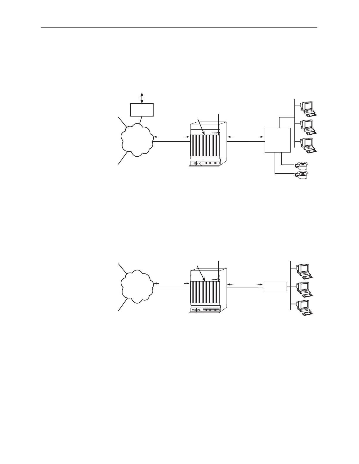
Network Configurations
Figure 1-1 shows the Hotwire ATM Line Card used to carry voice over DSL.
ISP
Corporate
Site
PSTN Voice
Traffic
Voice
Gateway
AT M
Network
ATM Cells
Hotwire ATM
Line Card
SCM
ATM Cells
DSL
GranDSLAM
Customer Premises
LAN
Integrated
Access
Device
(IAD)
00-16682
Figure 1-1. Endpoint with Voice Interfaces
Figure 1-2 shows a configuration in which the endpoints include a router to provide
data encapsulation.
ISP
Hotwire ATM
Line Card
SCM
Customer Premises
LAN
AT M
Network
Corporate
Site
ATM Cells
GranDSLAM
ATM Cells
DSL
Router
00-16681-01
Figure 1-2. Router Endpoint
1-4 February 2003 8335-A2-GB20-70
Page 13

SNMP Management Capabilities
1. About the Hotwire ATM Line Cards
The Hotwire ATM Line Cards support SNMP Version 1, and can be managed by
Paradyne’s OpenLane
®
or any industry-standard SNMP manager.
Management Information Base (MIB) Support
For a detailed description of supported MIBs, visit Paradyne’s Web site at
www.paradyne.com. The following MIBs are supported:
ATM Forum SNMP M4 Network Element View (af-nm-0095.001)
Definitions of Managed Objects for the ADSL Lines (RFC 2662)
Definitions of Managed Objects for ATM Management (RFC 2515)
Definitions of Managed Objects for HDSL2 and SHDSL Lines
(draft-ietf-adslmib-hdsl2-10.txt)
Definitions of Textual Conventions and OBJECT-IDENTITIES for ATM
Management (RFC 2514)
Evolution of MIB II Interfaces (RFC 2863)
ADSL Extension MIB (Model 8365 only) (draft-ietf-adslmib-adslext.txt)
SHDSL MIB (Model 8385 only) (draft-ietf-adslmib-hdsl2.txt)
Entity MIB Using SMIv2 (RFC 2037)
SNMP Trap Support
MIB II and the Interfaces Group MIB (RFC 1213, RFC 2233)
Paradyne enterprise MIBs for:
— Hotwire xDSL Interface
— SLE Device Control
— SLE Device Health and Status
— MaxVciVpi-MIB Table
—IF-MIB Table
— ATM VPL Statistics Table
The Hotwire ATM Line Cards support SNMP traps as shown in Appendix B,
Traps
.
SNMP
8335-A2-GB20-70 February 2003 1-5
Page 14

1. About the Hotwire ATM Line Cards
1-6 February 2003 8335-A2-GB20-70
Page 15
Menus and Screens
Menu and Screen Formats
The Hotwire DSLAM has an ASCII-based menu- and screen-driven user interface
system that enables the user to configure and monitor the Hotwire cards. This
section describes the components of a typical Hotwire menu and screen.
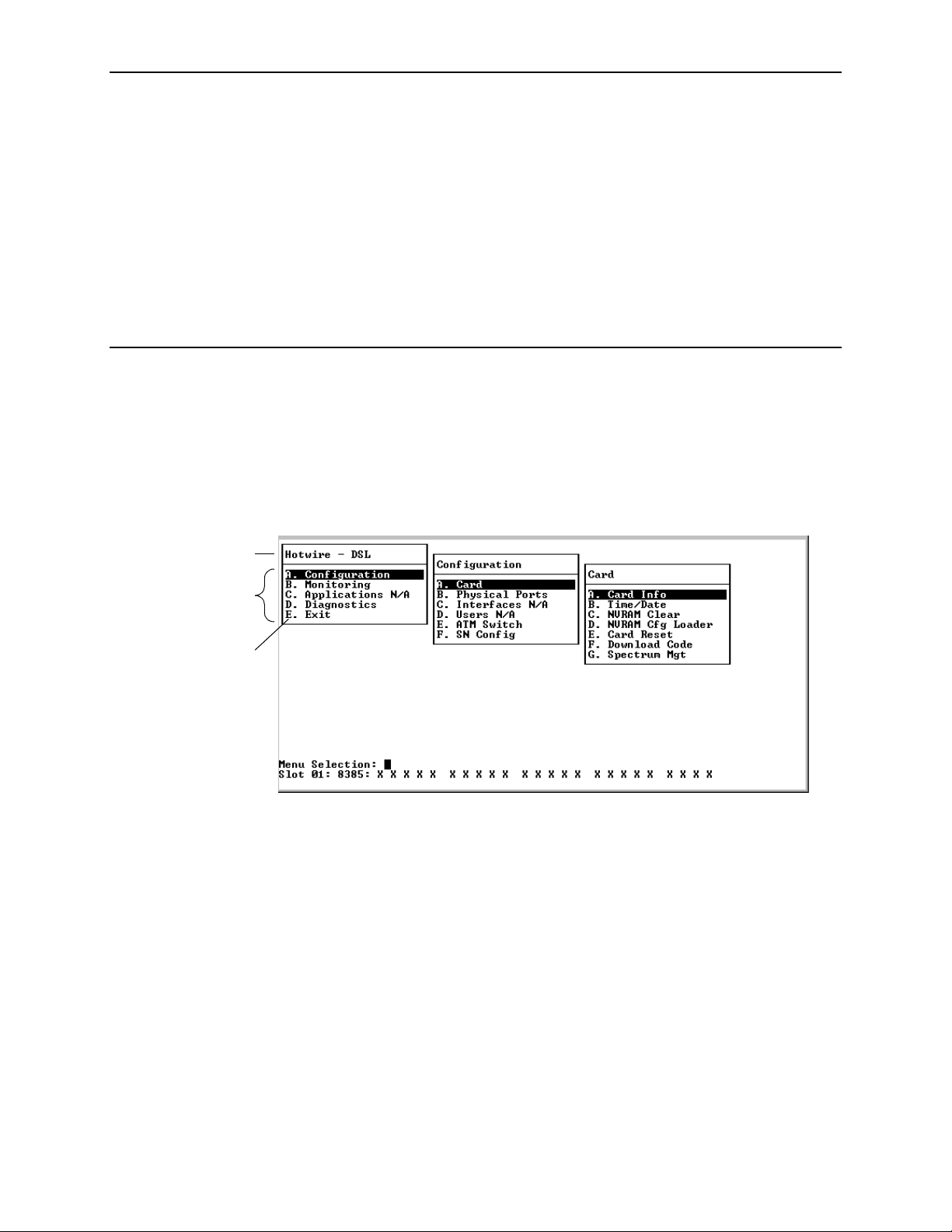
A typical Hotwire menu format is shown below:
1
2
2
3
1. Menu Title is the top line of the menu window that displays the title of the
menu or submenu.
2. Menu List is the portion of the menu window that displays the list of menu
options. When selected (by using the up and down arrow keys to move the
cursor position), a menu option displays a submenu window.
3. Letter Navigation Keys are provided within a menu list. These keys provide
an alternative method for selecting menu items.
For example, from the Hotwire – DSL menu illustrated above, you can press
the A key to select the Configuration menu item. The Configuration menu
appears. You can then press the A key to select the Card Status menu item,
and subsequently the Card Info menu item.
Some menu items not active for this product are displayed as placeholders in
the menu lists so that letter navigation keys are the same for all related
products.
8335-A2-GB20-70 February 2003 2-1
Page 16

2. Menus and Screens
Components of a Hotwire Screen
A typical Hotwire screen looks like this:
2
3
4
1
1. System Header Line is the top right line of the screen. This line contains two
fields of system login information:
— The first field displays a user-defined chassis or individual card name. If
you have not defined the system name, <no name> appears.
— The second field displays the previous remote or local login depending on
what is currently displayed in the middle field (such as the current login). If
the current login is local, the last field displays the previous remote login.
If the current login is remote, the last field displays the previous local
login.
2. Display Area is the main body of the screen. This area contains the screen
name in a “tab” at the upper left, and fields displaying data and/or requiring
input. The input values themselves are entered in the Input Line at the bottom
of the screen.
3. Input Line is in the lower area of the screen. This area displays prompts after
which you enter values for the field highlighted in the Display Area.
If a field has predefined permitted values, you need only type enough of a
value to distinguish it from other permitted values. For example, if the
Behavior field has a value of Fixed or AutoBaud, you need only type f or a,
respectively, and press Enter, to select a value.
2-2 February 2003 8335-A2-GB20-70
Page 17

2. Menus and Screens
4. Status Line is the last line of the screen. It displays status about the selected
card and all interfaces. Each time the screen is refreshed, one of the following
lines is displayed in rotation:
Line 1:
Slot 02: 8335: Card Status: _ _ _ Wan Status: U
Line 2: Slot 02: 8335: D D D D D D D D D D D D D D D D
Line 3: Slot 02: 8335: Press ? For Help
Line 1 Text Description
Slot
nn
Slot
8335, 8355, 8365, or
8385
Card Status:
_ or T
_ or M
_ or R
Slot number of the card
Model number of selected card
Test mode. Card currently in test mode (T) or _ for no active
test.
Major alarm. Major alarm present on card (M) or _ for no
active mralar byuyu2.7(r).0034 Tc-0.0014 Tw[(2ct)14.8(412.4(mbeMi)(n)-11r)-.7( p12.1(TD0)-7.1 b)2m.1.16 TDMin7( p12)]TJ-7.(u7( p12.1(TD0)-7.1 b)2m.3(( p12r).6( -1.8.5(e)1.16 TD2.1c1.8.5a]TJ-7.d(( p1211.R5(am).2(o)11.82)-5.9( 78.5)]TJ-7.e )1-12.o12.7(52.8( m5(n7( p12)]TJ-7.(0035 Tc-0.0015 Tw[47ct)14.8(12.8(r)5)9.7()-8.12(r)-m)-1.(n)4)]TJ01.16()-.7 TD0.0033 Tc-0.0813 4.8(i93-4(rd)91)3( T)]TW.3(5a]T16 TD 0.2( )-1216(m))-1216(mu]T16 TDn)1467 :0034 Tc-0.0014 -d)9.3( c3)13.3(8T)]TD f)26-8.129.3(.16 TDUTD0.0039 Tc.0014 Tw[Ma)12.7(jo2.4(mbeUber)3(o)16 TDli.3(f)2nk3.3(d )sta)16 TDt)(t)s3.3(d :0034 Tc-0.0014 -d)9.14( c3)13.33(8T)]TD Tf07(=1.333Do)78.5wna)-1412..8.5 U=Up76 53.6145 TD0797 107.881 Tm0.0022 406 T2Tj9 0 0 9Line 1 Tex2 Description
Naming Conventions for Ports and Interfaces
Special naming conventions exist for the Port Name and Interface Name fields.
Port Name – Identifies a physical port. It consists of a family name (dsl for a
DSL card), and a port number. The port number can range from 1 to the
number of ports on the card. For example: dsl12.
Interface Name – Identifies a logical connection. It consists of a family name
and a port number (same as the port name), followed by a number identifying
a logical interface on the port. Currently the interface number is limited to 1.
For example: dsl12:1.
8335-A2-GB20-70 February 2003 2-3
Page 18

2. Menus and Screens
General Navigation Keys
Table 2-1. General Navigation Keys
Keys Definition
Backspace, Del, Ctrl-d Erases the character to the left of the prompt.
Ctrl-e Returns to the card selection screen from any screen.
Ctrl-r Resets counters (on monitoring statistics displays).
Ctrl-u Clears the current input or prompt line.
Ctrl-v Displays pop-up menus.
Esc h, ? Displays the online Help screen.
Esc l, Ctrl-l Refreshes the screen.
Esc n Goes to the next window.
Esc p, Ctrl-z Goes back to the previous window.
Esc t, Ctrl-a, Ctrl-c,
Ctrl-t, or Ctrl-y
Left arrow, Ctrl-b Moves the cursor to the left.
Right arrow, Ctrl-f Moves the cursor to the right.
Up arrow, Ctrl-p Moves up to the previous menu selection or entry field.
Down arrow, Ctrl-n Moves down or to the next selection.
Enter Accepts entry.
Pop-Up Menu Navigation Keys
Table 2-2. Pop-Up Menu Navigation Keys
Keys Definition
Ctrl-w Scrolls up one page.
Ctrl-x Scrolls down one page.
Up Arrow, Ctrl-p Moves cursor up one menu item.
Down Arrow, Ctrl-n Moves cursor down one menu item.
Goes back to the original, top-level window.
Ctrl-z Exits pop-up menu without accepting selected entry.
Enter Accepts selected entry and exits pop-up menu.
2-4 February 2003 8335-A2-GB20-70
Page 19
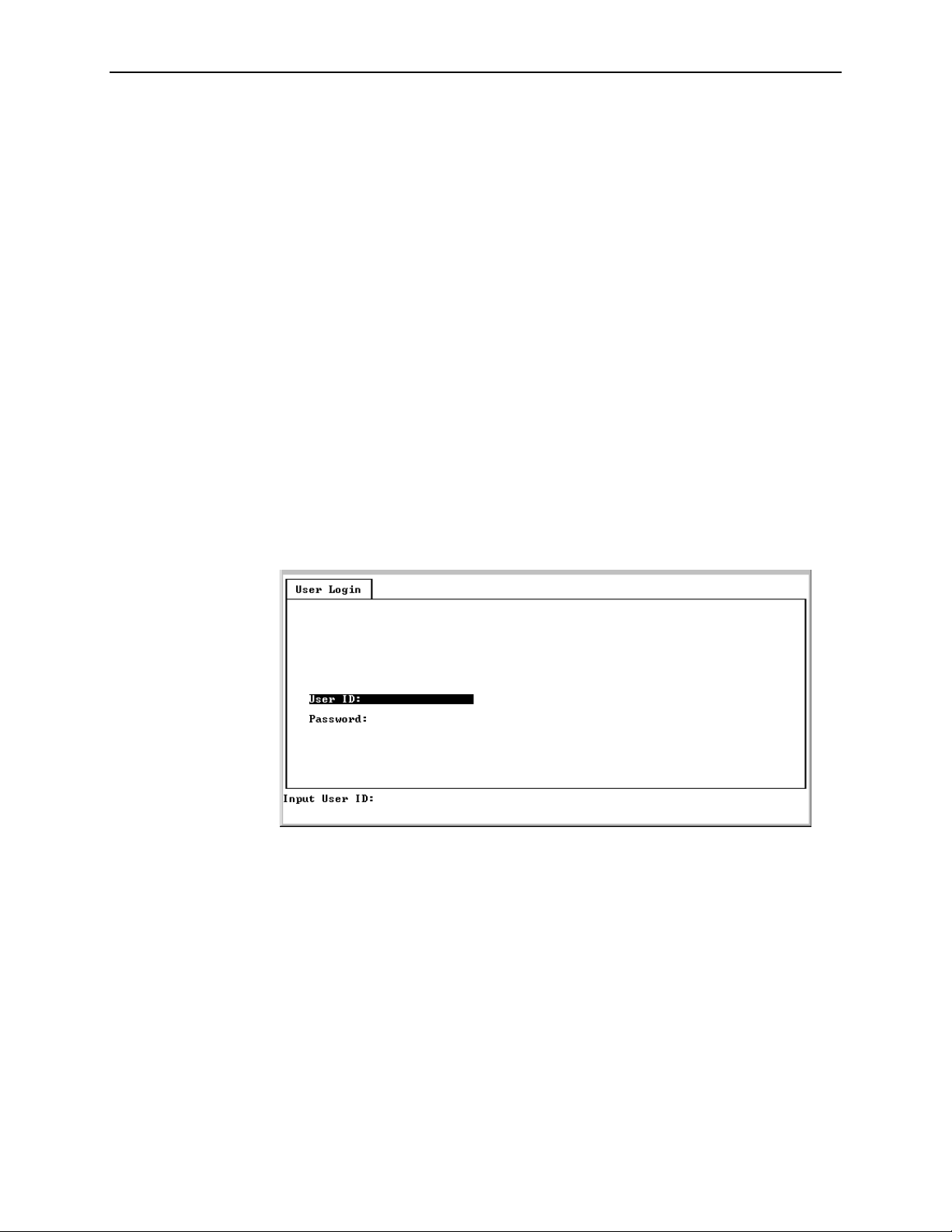
User Login Screen (MCP)
You can log in to the Hotwire DSL system using either a local VT100-compatible
terminal or a remote Telnet connection. However, the Hotwire DSL system
accepts only one login session at a time.
The User Login screen appears if one or more users have been defined on the
Management Communications Processor (MCP).
Enter your login ID and password. The login ID and password are case-sensitive.
If you have RADIUS Authentication, this verification may take several minutes as
each RADIUS server is contacted one at a time.
If you are denied access during a Telnet session, the session stops and an error
is logged. If you are using a console, you are automatically returned to the User
Login screen.
NOTE:
If you forget your password, contact your Technical Service Center. Have the
serial number of the MCP card available, and the service representative will
provide you with a password.
2. Menus and Screens
After entering your login ID and password, the system displays the Hotwire
Chassis Main Menu.
8335-A2-GB20-70 February 2003 2-5
Page 20
2. Menus and Screens
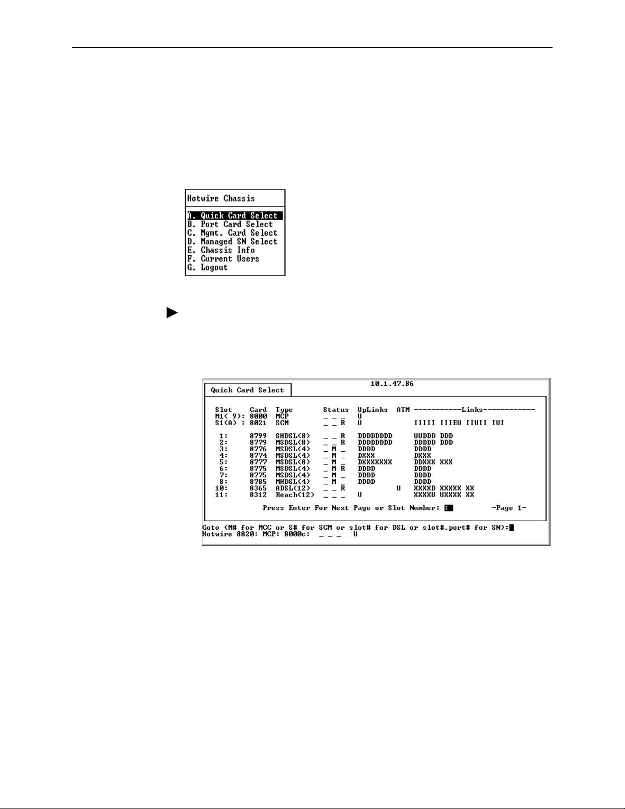
Quick Card Select Screen
The Quick Card Select screen displays all the cards in the chassis and lets you
Telnet to a selected card in the chassis. Information is displayed only for
populated slots. See the
(MCC) Card, IP Conservative, User’s Guide
Hotwire Chassis Main Menu.
Procedure
Hotwire Management Communications Controller
for more information about the
To select a card:
1. From the Hotwire Chassis Main Menu, select A for Quick Card Select.
2. At the Goto: prompt, type the slot number of the desired card and press
Enter.
The appropriate menu appears.
2-6 February 2003 8335-A2-GB20-70
Page 21

2. Menus and Screens
The following information is displayed on the Quick Card Select screen.
Table 2-3. Quick Card Select Screen
Column
Heading Display Description
Slot <slot number> Slot number of card in chassis.
Card <model number> Model number of card.
Type <card type(ports)> Card type followed, if appropriate, by the number of
ports it supports. For example, SCM, SDSL(16),
Reach(24), ADSL(12),or SHDSL(24).
Status Position 1: T or _ Test mode. Card currently in test mode or _ for no
active test.
Position 2: M or _ Major alarm. Major alarm present on card or _ for no
active major alarm.
Position 3: R or _ Minor alarm. Minor alarm present on card or _ for no
minor alarm active.
UpLinks <uplink status> Status of uplink:
U=Up, D=Down, X=Disabled, A=Alarm
ATM <ATM uplink status> Status of ATM uplink:
U=Up, D=Down, X=Disabled, A=Alarm
Links <dsllink status> Status of DSL ports:
U=Up, D=Down, X=Disabled, A=Alarm, E=Empty slot
8335-A2-GB20-70 February 2003 2-7
Page 22

2. Menus and Screens
Exiting from the System
You can manually log out of the system or, after a set number of minutes of
inactivity, the system will automatically log you out.
Manually Logging Out
Procedure
To exit from the Hotwire DSL system:
1. Return to the Card Selection screen by selecting Exit from either the
Hotwire – MCC menu or the Hotwire – DSL menu.
2. Press Ctrl-z.
3. From the Hotwire Chassis Main Menu, select Logout.
The system exits from the current login session on the Hotwire DSL system.
Automatically Logging Out
The DSL system has an automatic timeout feature that logs you out of the system
after five minutes (on the MCP) or ten minutes (on the line card) of inactivity. You
will need to log back in to continue your work.
To log back in, press Enter to display the User Login screen and log in.
2-8 February 2003 8335-A2-GB20-70
Page 23

Configuration
Overview
This chapter provides instructions on how to access the system for the first time
and perform initial setup procedures. These procedures may include:
3
Entering Card Information
Setting Spectrum Management (Models 8355 and 8385)
Configuring the DSL Ports
Configuring the ATM Physical Layer (Models 8335, 8365, and 8385)
page 3-24
on page 3-2
on page 3-4
on page 3-8
on
Configuring ATM Parameters
Configuring ATM Cross Connections
Configuring ATM Traffic Profiles
Clearing Cross Connections
Configuring Rate Shaping (Models 8335, 8365, 8385)
Entering Service Node Management Configuration Information (Models 8335
and 8385)
In cases where there is a substantive difference between the screens for the
different card models, an example for each card model is shown. For most
screens the only difference is the model number and number of ports displayed in
the message area.
on page 3-42
on page 3-26
on page 3-28
on page 3-32
on page 3-37
Saving and Restoring Configuration Options
If you have a saved configuration options file you would like to download to the
card, or if you would like to save a copy of the current configuration file, use the
NVRAM Configuration Loader screen. See
Configuration
in Chapter 6,
Maintenance Procedures
on page 3-38
Uploading and Downloading a
.
If you have altered configuration options in error and would like to ensure that you
are using factory default configuration options, use the Clear NVRAM screen to
restore them. See
8335-A2-GB20-70 February 2003 3-1
Clearing NVRAM
in Chapter 6,
Maintenance Procedures.
Page 24
3. Configuration
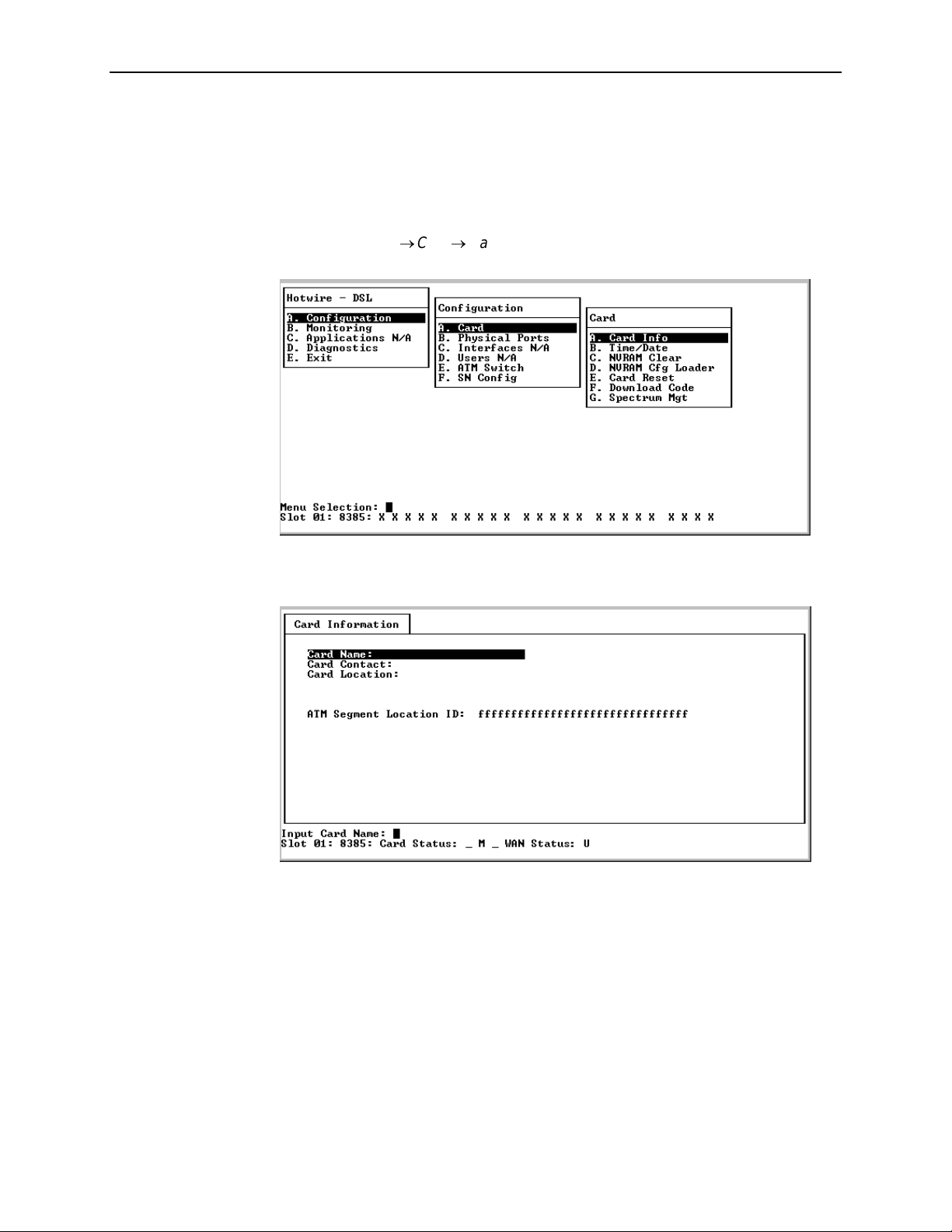
Entering Card Information
After accessing your line card for the first time, use the Card Information screen to
configure basic information about the card. To access the Card Information
screen, follow this menu selection sequence:
Configuration→Card→Card Info
The Card Information screen appears.
(A-A-A)
3-2 February 2003 8335-A2-GB20-70
Page 25

3. Configuration
Procedure
To enter Card Information screen information:
1. Position the cursor in the field you wish to modify. Type the value you want and
press Enter.
For . . . Enter . . .
Card Name Up to 16 alphanumeric characters to identify the card
(Default = blank).
Card Contact Up to 32 alphanumeric characters to identify the
person or organization responsible for the card
(Default = blank).
Card Location Up to 16 alphanumeric characters to identify the
location of the card (Default = blank).
ATM Segment Location IDUp to 32 alphanumeric characters to identify the card for
F5 OAM segment loopbacks. If the card receives an
OAM loopback cell with a segment loopback destination
ID matching the value entered in this field, the card will
loop the cell back to the originator (Default = all ones).
Refer to ITU-T I.610 for required structure.
2. Save the changes as prompted.
8335-A2-GB20-70 February 2003 3-3
Page 26

3. Configuration
Entering the Time and Date
The Time/Date screen of the Configuration branch of the line card (menu
sequence A-A-B) displays time, time zone, and date. The values are configured
through the MCP and cannot be modified through the line card. For more
information about the Time/Date screens, see
Information
Communications Controller (MCC) Card, IP Conservative, User’s Guide
complete information.
in Chapter 4,
Monitoring.
Refer to the
Viewing Card Status and
Hotwire Management
Setting Spectrum Management (Models 8355 and 8385)
The Spectrum Management screen of the Configuration branch of the Model 8355
and Model 8385 line card (menu sequence A-A-G) sets the unique regional
operational parameters to use for this card. For the Model 8385, the selections
differ depending on whether you are using the card in Notrh American (Annex A)
or European (Annex B) networks.
The purpose of Spectrum Management is to facilitate a reasonable spectral
environment for the coexistence of multiple technologies in the loop plant with an
acceptable level of crosstalk between them. In some countries, the DSL service
provider must meet the spectrum management specification of that country. For
example, in the United Kingdom, it is a requirement that the product comply with
OFTel PSD mask for the loop length requested (short, medium or long). Support
for this requirement is provided by enabling the Spectrum Management option on
the Spectrum Management screen (A-A-G), and properly setting the Line Length
and EWL options on the Port Configuration screen (A-B-B).
for
NOTE:
Settings on the Spectrum Management screen affect the choices available for
the DSL Port Configuration screen (menu sequence A-B-B). See
Configuration – Model 8355
Model 8385
on page 3-19 for more information.
on page 3-11 and
DSL Port Configuration –
DSL Port
3-4 February 2003 8335-A2-GB20-70
Page 27
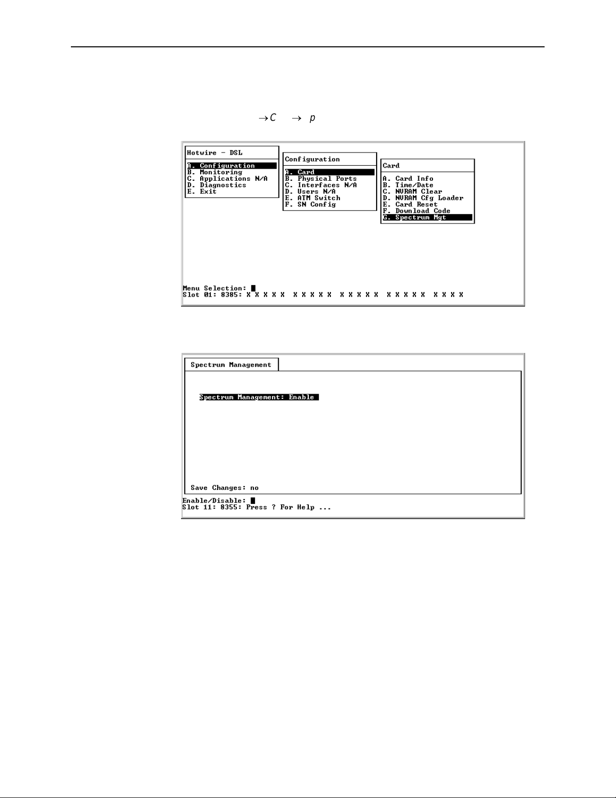
3. Configuration
To access the Spectrum Management screen, follow this menu selection
sequence:
Configuration→Card→Spectrum Mgt
(A-A-G)
For the Model 8355, the following Spectrum Management screen appears.
8335-A2-GB20-70 February 2003 3-5
Page 28
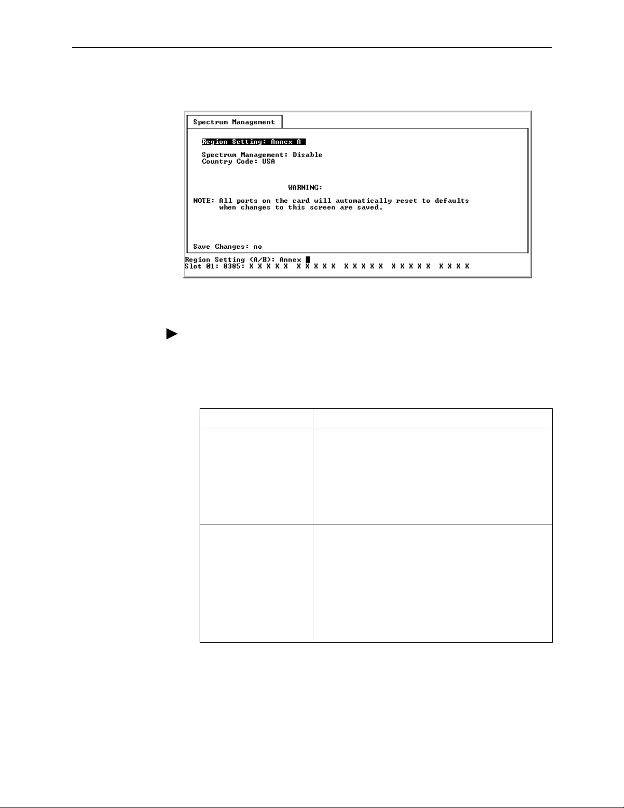
3. Configuration
For the Model 8385, the following Spectrum Management screen appears.
Procedure
To enter Spectrum Management screen information:
1. Position the cursor in the field you wish to modify. Type the value you want and
press Enter.
For . . . Enter . . .
Region Setting
(Model 8385 only)
Spectrum Management Enable/Disable to limit the DSL speeds on each port
The unique regional SHDSL operational parameters as
defined in ITU G.991.2 that are to be used for this card
(Default = Annex A).
Annex A – The operational parameters for North
America will be used.
Annex B – The operational parameters for Europe will be
used.
(based on line length) to meet either ANSI T1.417 or BT
Access Network Spectrum standard requirements. The
selection allows for an acceptable level of crosstalk from
multiple technologies in the loop plant as defined by
these standards (Default = Enable for Model 8385.
Default = Disable for Model 8355 cards.).
Enable – Enables Spectrum Management support.
Disable – Disables Spectrum Management support.
3-6 February 2003 8335-A2-GB20-70
Page 29

For . . . Enter . . .
3. Configuration
Country Code
(Model 8385 only)
2. Save the changes as prompted.
Other Functions of the Card Menu
See Chapter 6,
functions of the
Reset.
Maintenance Procedures
Configuration→Card
The Spectrum Management standard to be used on
this Model 8385 card to calculate the speeds
allowable to comply with Spectrum Management
(Default = USA).
USA – The T1.417 Spectrum Management standard for
USA will be used. This setting is only available when
Region Setting is set to Annex A.
UK – The ANFP Spectrum Management standard for
BT Access Network will be used. This setting is only
available when Region Setting is set to Annex B.
, for information about the other
menu, such as NVRAM Clear and Card
8335-A2-GB20-70 February 2003 3-7
Page 30
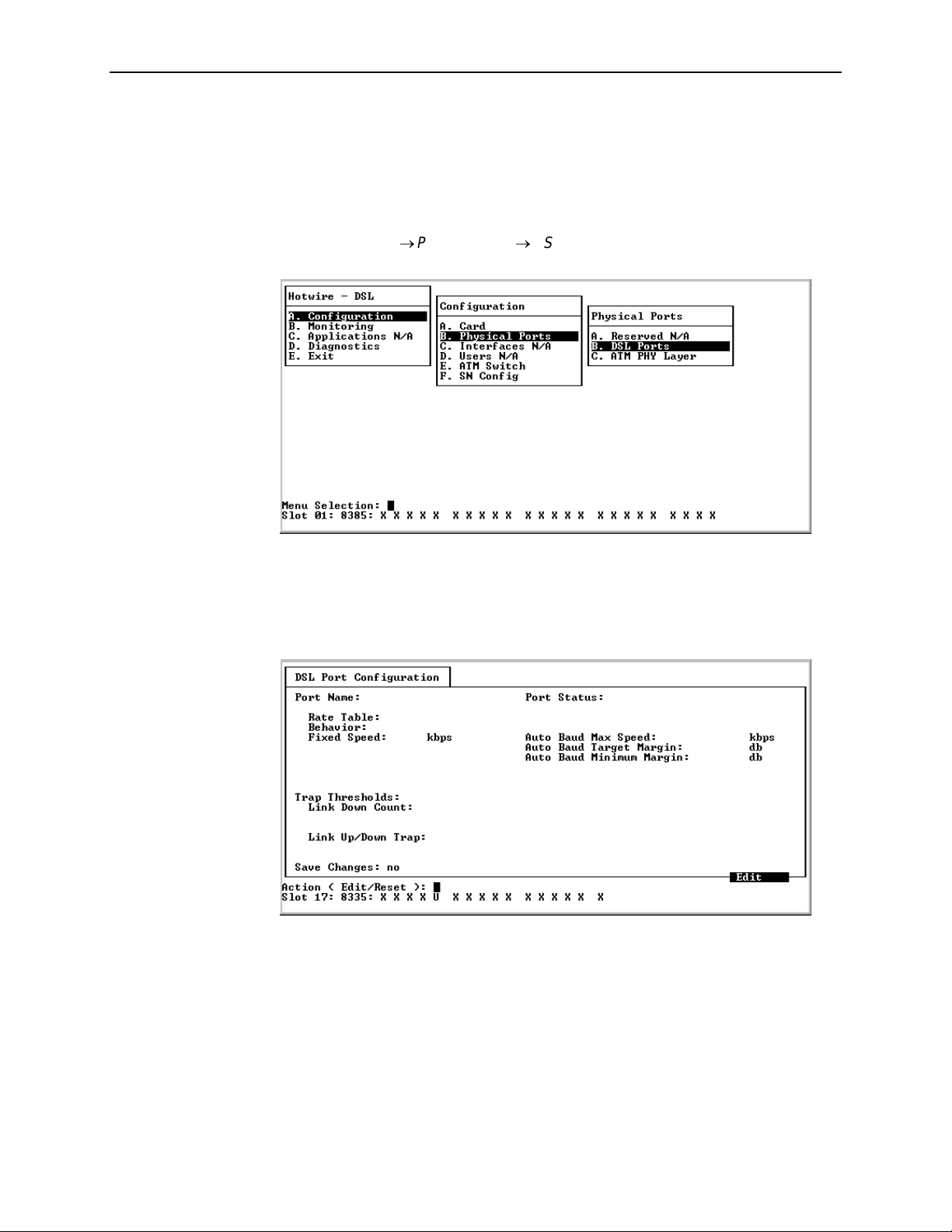
3. Configuration
Configuring the DSL Ports
Set the rate and other characteristics of the DSL ports from the DSL Port
Configuration screen. To access the DSL Port Configuration screen, follow this
menu selection sequence:
Configuration→Physical Ports→DSL Ports
DSL Port Configuration – Model 8335
For the Model 8335, the following DSL Port Configuration screen appears.
(A-B-B)
3-8 February 2003 8335-A2-GB20-70
Page 31

3. Configuration
Procedure
To enter DSL Port Configuration screen information for the Model 8335:
1. Select an Action:
Edit – To edit fields on the screen.
Reset – To enable the port and cause the DSL line to retrain.
2. Select the Port Name of the port to be configured or reset (dsl1 through
dsl16).
3. For Edit mode, position the cursor in the field you wish to modify. Type the
value you want and press Enter.
NOTE:
Fixed rate and autobaud are the two methods used for synchronizing the
DSL line between the central office equipment and the customer premises
equipment.
— Fixed rate is used for applications that cannot tolerate having the
speed of the DSL link change (for example, a TDM application). Fixed
rate is the fastest method, and it always trains at the same speed.
However, depending on line conditions, training may not occur without
errors.
— Autobaud is used for applications that can tolerate having the speed
of the DSL link change (for example, IP traffic). The autobaud
algorithm sets the DSL link to the highest error-free speed. Autobaud
may try several speeds to find the best rate for the line conditions. As
a result, autobaud usually takes longer to train than fixed rate. The
training time for autobaud will vary with the line conditions, with some
line conditions causing the algorithm to take several minutes.
Regardless of which training mode is used, both DSL units must be set to
the same mode.
8335-A2-GB20-70 February 2003 3-9
Page 32

3. Configuration
For . . . Enter . . .
Rate Table Standard – Selects the standard rate table for use when
operating with standard endpoints.
Nx128 – Selects the Nx128 rate table for use when operating
with nonstandard endpoints (most are multiples of 128).
Behavior The training behavior (Default = Auto Baud):
Fixed – The line card will train only at the rate set in the Fixed
Speed field (Standard default = 784 kbps; Nx128 default =
768 kbps).
Auto Baud – The line card will train up to the highest
operational rate less than or equal to the rate set in Auto Baud
Max Speed.
Fixed Speed The DSL line rate if Behavior is set to Fixed:
Available Standard rates are 144, 272, 400, 528, 784, 1168,
1552, or 2320 kbps (Default = 784 kbps).
Available Nx128 rates are 144, 256, 384, 512, 768, 1024, or
1536 kbps (Default = 784 kbps).
Auto Baud Max
Speed
Auto Baud Target
Margin
Auto Baud
Minimum Margin
Link Down Count A number from 0 to 900 (Default = 0 (disable).
Link Up/Down Trap Enable or Disable to enable/disable link up/down traps
The maximum DSL line rate the card can train to if Behavior is
set to Auto Baud:
Available Standard rates are 144, 272, 400, 528, 784, 1168,
1552, or 2320 kbps (Default = 2320 kbps).
Available Nx128 rates are 144, 256, 384, 512, 768, 1024, or
1536 kbps (Default = 1536 kbps).
A range of 0 to 15 dB. The upper limit for margin used by the
Autobaud algorithm during training. After training, if the margin
is greater than the target margin, the card will attempt to retrain
at a higher rate, if the DSL line conditions permit. This field only
appears if Autobaud is selected (Default = 9 dB).
A range of 0 to 15 dB. The lower limit for margin used by the
Autobaud algorithm during training. After training, if the margin
is less than the minimum margin, the card will attempt to retrain
at a lower rate. This field only appears if Autobaud is selected
(Default = 5 dB).
If the number of DSL Link Down events exceeds the selected
number within a 15-minute period, an SNMP trap is sent. If
Link Down Count is set to Disable, no Link Down trap is ever
sent.
(Default = Enable).
Enable – Enables link up/down traps.
Disable – Disables link up/down traps.
4. Save the changes as prompted.
3-10 February 2003 8335-A2-GB20-70
Page 33

DSL Port Configuration – Model 8355
For the Model 8355, the DSL Port Configuration screen appears. The options
displayed depend on whether Spectrum Management is enabled and what
settings are specified in the device’s factory initialization file.
3. Configuration
Edit/Reset Model 8355 DSL Ports
Procedure
To enter DSL Port Configuration screen information for the Model 8355:
1. Select an Action:
Edit – To edit fields on the screen.
Reset – To enable the port and cause the DSL line to retrain.
Copy – To copy a DSL port configuation (see
Configurations
on page 3-15).
2. Select the Port Name of the port to be configured or reset (dsl1 through
dsl24).
3. For Edit mode, position the cursor in the field you wish to modify. Type the
value you want and press Enter.
Copy Model 8355 DSL Port
8335-A2-GB20-70 February 2003 3-11
Page 34

3. Configuration
For . . . Enter . . .
EWL (Equivalent
Working Length)
Loop Length The relative loop length of the line. This value is used to
Quad The quad cable configuration. This value is used to limit
The estimated length of the line in kilofeet. This value is
usually specified by the carrier. This option is available only
if Spectrum Management is set to Enable on the Spectrum
Management screen (menu selection A-A-G) and the
equivalent working length parameter is specified in the
device’s factory initialization file.
EWL = L26 + 3(L24)/4, where L26 is the total length of the
26-gauge cable in the loop excluding any bridged tap and
L24 is the total length of 19, 22, or 24-gauge cable in the
loop excluding any bridged tap.
8.5 – 14.5 kft in .5 kft increments, or >14.5 kft
(Default = 10 kft).
limit transmit rates and maximum transmit power settings
according to local spectrum management guidelines, and is
usually specified by the carrier. This option is available only
if Spectrum Management is set to Enable on the Spectrum
Management screen (menu selection A-A-G), and if
relative loop length is specified in the device’s factory
initialization file.
Short
Medium
Long
transmit rates and maximum transmit power settings
according to local spectrum management guidelines, and is
usually specified by the carrier. This option is available only
if Spectrum Management is set to Enable on the Spectrum
Management screen (menu selection A-A-G), and if the
quad cable configuration is specified in the device’s factory
initialization file.
Same
Segregated<=3km
Segregated>3km
POTS Detection
Volt age
Maximum Tx Power
ATU-C/ATU-R
The voltage used to detect the presence of Plain Old
Telephone Service (POTS) on the DSL line:
0 – 74 volts in 1 volt increments, or D for Disable
(Default = 3 volts).
The maximum transmission power settings for the ADSL
Transmission Unit – Central Office (ATU-C) and ADSL
Transmission Unit – Remote Site (ATU-R). The range may
be limited according to local guidelines when Spectrum
Management is set to Enable on the Spectrum
Management screen (menu selection A-A-G):
+12dB – -14dB in 1 dB increments (Default = +12dB)
3-12 February 2003 8335-A2-GB20-70
Page 35

3. Configuration
For . . . Enter . . .
Line Profile The name of the general line configuration profile (up to
32 alphanumeric characters). Press Ctrl-v to display a list
of all available line profiles configured on the card. Either
select an existing profile to change, or select New Profile to
create a new line configuration profile. An asterisk (*)
indicates the profile is referenced by other ports.
Each profile name must be unique. Up to 30 profiles can be
configured. Profiles can be used by multiple ports and can
be changed at any time. All ports share a single default line
configuration profile as part of the factory defaults.
Maximum Tx Rate, Minimum Tx Rate, and Target SNR
Margin are part of the general line configuration profile.
Maximum Tx Rate
ATU-C/ATU-R
Minimum Tx Rate
ATU-C/ATU-R
The maximum transmission rate for the ATU-C and ATU-R.
The range may be limited according to local guidelines
when Spectrum Management is set to Enable on the
Spectrum Management screen (menu selection A-A-G):
All cards with Spectrum Management disabled:
ATU-C: 32 − 2176 kbps in 32 kbps increments
(Default = 2176 kbps)
ATU-R: 32 − 2176 kbps in 32 kbps increments
(Default = 2176 kbps)
Cards with Spectrum Management enabled and
EWL
≤
11.5 kbps:
ATU-C: 32 − 2176 kbps in 32 kbps increments
(Default = 2176 kbps)
ATU-R: 32 − 1632 kbps in 32 kbps increments
(Default = 1632 kbps)
Cards with Spectrum Management enabled and
EWL > 11.5 kft:
ATU-C: 32 − 1440 kbps in 32 kbps increments
(Default = 1440 kbps)
ATU-R: 32 − 1088 kbps in 32 kbps increments
(Default = 1088 kbps)
The minimum transmission rate acceptable for the ATU-C
and ATU-R. Any rate below this, sustained for at least
3 seconds, generates a Loss of Signal (LOS) status.
32 kbps – 2176 kbps in 32 kbps increments
(Default = 32 kbps).
8335-A2-GB20-70 February 2003 3-13
Page 36

3. Configuration
Target SNR Margin
ATU-C/ATU-R
Alarm Profile The name of the alarm configuration profile (up to
The Signal-to-Noise Ratio (SNR) margin relative to a Bit
Error Ratio of 10
the port for the ATU-C and ATU-R. The maximum SNR is
always 16 dB, while the minimum is always 0 dB. The SNR
margin for rate downshift is 3 dB below the Target SNR
Margin. When the SNR margin falls below this level, the
device will attempt to decrease its transmit rate. The SNR
margin for rate upshift is 2 dB above the Target SNR
Margin. When the noise margin rises above this level, the
device will attempt to increase its transmit rate. Rate shifts
occur as soon as the margin threshold is exceeded.
3 dB – 14 dB in 1 dB increments (Default = 4 dB).
32 alphanumeric characters). Press Ctrl-v to display a list
-7
required for a successful activation of
3-14 February 2003 8335-A2-GB20-70
Page 37

For . . . Enter . . .
3. Configuration
Loss of Power Seconds
Trap Threshold
AT U- R
Rate Increase
ATU-C/ATU-R
Rate Decrease
ATU-C/ATU-R
Link Up/Down Trap Enable or Disable to enable/disable link up/down traps
Initialization Failure
Tr ap
AT U- C
A number from 0 to 900, or a D for Disable
(Default = Disable).
If the number of Loss of Power Seconds (LOP) events
equals or exceeds the selected number within a 15-minute
period, an SNMP trap is sent. If set to Disable or 0, no LOP
trap is ever sent. If set to 1, a trap is sent after each LOP
event.
0 to 2176 kbps in 32 kbps increments, or a D for
Disable (Default = Disable).
If the current rate is greater than or equal to the previous
rate, plus this threshold, an SNMP trap is sent. If set to
Disable, traps are disabled for the event.
0 to 2176 kbps in 32 kbps increments, or a D for Disable
(Default = Disable).
If the current rate is less than or equal to the previous rate,
minus this threshold, an SNMP trap is sent. If set to 0, traps
are disabled for the event.
(Default = Enable).
Enable – Enables link up/down traps.
Disable – Disables link up/down traps.
Enable or Disable to enable/disable InitFailure traps as
specified in RFC 2662 (Default = Disable).
Enable – Enables InitFailure traps.
Disable – Disables InitFailure traps.
4. Save the changes as prompted.
Copy Model 8355 DSL Port Configurations
Procedure
To copy DSL Port Configuration screen information for the Model 8355 to/from
another port:
1. Select an Action:
Copy – To copy the configuration of one port to another port.
2. Enter the name of the source port to be copied (dsl1 through dsl24) in the
Copy From field.
3. Enter the name of the destination port for the configuration information (dsl1
through dsl24) in the Copy To field.
4. Enter yes at the Save Changes? prompt to copy.
8335-A2-GB20-70 February 2003 3-15
Page 38

3. Configuration
DSL Port Configuration – Model 8365
For the Model 8365, the following DSL Port Configuration screen appears.
Procedure
To enter DSL Port Configuration screen information for the Model 8365:
1. Select an Action:
Edit – To edit fields on the screen.
Reset – To enable the port and cause the DSL line to retrain.
2. Select the Port Name of the port to be configured or reset (dsl1 through
dsl12).
3. For Edit mode, position the cursor in the field you wish to modify. Type the
value you want and press Enter.
For . . . Enter . . .
Line Code The physical transport method (Default = Multimode):
Multimode – The line card adapts to the code the endpoint
is set for.
DMT – The line code is G.dmt (ITU 992.1). The endpoint
must be set to G.dmt.
G.Lite – The line code is G.lite (ITU 992.2). The endpoint
must be set to G.lite.
ANSI – The line code is ANSI T1.413, Issue 2. The endpoint
must be set to ANSI.
3-16 February 2003 8335-A2-GB20-70
Page 39

3. Configuration
For . . . Enter . . .
Latency The data stream path for the port (Default = Interleaved):
Fast – The data stream uses the fast path between the
line card and the endpoint.
Interleaved – The data stream uses the interleaved path
between the line card and the endpoint.
Behavior The training behavior (Default = Adaptive):
Adaptive – The line card will train up to the highest
operational rate less than or equal to the rates set in the
Downstream Maximum Speed and Upstream Maximum
Speed fields.
Fixed – The line card will train only at the rates set in the
Downstream Speed and Upstream Speed fields.
Downstream Speed The downstream DSL line rate (in 32 kbps increments) the
card trains to if Behavior is set to Fixed:
DMT and ANSI: 32–8000 kbps (Default = 8000 kbps).
G.lite: 64–3008 kbps (Default = 1536 kbps).
Upstream Speed The upstream DSL line rate (in 32 kbps increments) the
card trains to if Behavior is set to Fixed:
DMT and ANSI: 32–832 kbps (Default = 832 kbps).
G.lite: 32–512 kbps (Default = 64 kbps).
Maximum
Downstream Speed
The maximum downstream DSL line rate (in 32 kbps
increments) the card can train to if Behavior is set to
Adaptive:
DMT and ANSI: 32–8000 kbps (Default = 8000 kbps).
G.lite: 64–3008 kbps (Default = 3008 kbps).
Minimum Downstream
Speed
The minimum downstream DSL line rate (in 32 kbps
increments) the card can train to if Behavior is set to
Adaptive:
DMT and ANSI: 32–8000 kbps (Default = 32 kbps).
G.lite: 64–3008 kbps (Default = 64 kbps).
Maximum Upstream
Speed
The maximum upstream DSL line rate (in 32 kbps
increments) the card can train to if Behavior is set to
Adaptive:
DMT and ANSI: 32–832 kbps (Default = 832 kbps). G.lite:
64–512 kbps (Default = 512 kbps).
Minimum Upstream
Speed
The minimum upstream DSL line rate (in 32 kbps
increments) the card can train to if Behavior is set to
Adaptive:
DMT and ANSI: 32–832 kbps (Default = 32 kbps).
G.lite: 32–512 kbps (Default = 64 kbps).
Target Margin The noise margin relative to a Bit Error Ratio of 10
-7
required for a successful activation of the port :
0–31 dB in 1 dB increments (Default = 4 dB).
8335-A2-GB20-70 February 2003 3-17
Page 40

3. Configuration
For . . . Enter . . .
Minimum Margin The noise margin relative to a Bit Error Ratio of 10-7 that the
port will tolerate before attempting to increase the far-end
output power:
0–31 dB in 1 dB increments (Default = 15 dB).
Maximum Margin The noise margin relative to a Bit Error Ratio of 10-7 and in
addition to the Target Margin that the port will tolerate before
attempting to reduce the far-end output power:
0–31 dB in 1 dB increments (Default = 15 dB)
Error Seconds A number from 0 to 900, or a D for Disable, for upstream
and downstream (Default = 120).
If the number of DSL Errored Second events equals or
exceeds the selected number within a 15-minute period, an
SNMP trap is sent. If set to Disable or 0, no Errored Second
trap is ever sent. If set to 1, a trap is sent after each Errored
Second event.
Severely Error
Seconds
Unavailable Seconds A number from 0 to 900, or a D for Disable, for upstream
SN Loss of Power
Count
Link Down Count A number from 0 to 900, or a D for Disable
A number from 0 to 900, or a D for Disable, for upstream
and downstream (Default = 15).
If the number of DSL Severely Errored Second (SES)
events equals or exceeds the selected number within a
15-minute period, an SNMP trap is sent. If set to Disable or
0, no SES trap is ever sent. If set to 1, a trap is sent after
each SES event.
and downstream (Default = 1).
If the number of DSL Unavailable Second (UAS) events
equals or exceeds the selected number within a 15-minute
period, an SNMP trap is sent. If set to Disable or 0, no
Unavailable Seconds trap is ever sent. If set to 1, a trap is
sent after each UAS event.
A number from 0 to 900, or a D for Disable
(Default = 1).
If the number of remote Loss of Power (LOP) events equals
or exceeds the selected number within a 15-minute period,
an SNMP trap is sent. If set to 0, no LOP trap is ever sent. If
set to 1, a trap is sent after each SN LOP event.
(Default = 0).
If the number of DSL Link Down events equals or exceeds
the selected number within a 15-minute period, an SNMP
trap is sent. If set to Disable or 0, no Link Down trap is ever
sent. If set to 1, a trap is sent for each Link Down Count
event.
3-18 February 2003 8335-A2-GB20-70
Page 41

For . . . Enter . . .
Link Up/Down Trap Enable or Disable to enable/disable link up/down traps
4. Save the changes as prompted.
DSL Port Configuration – Model 8385
For the Model 8385, the following DSL Port Configuration screen appears.
3. Configuration
(Default = Enable).
Enable – Enables link up/down traps.
Disable – Disables link up/down traps.
Procedure
To enter DSL Port Configuration screen information for the Model 8385:
1. Select an Action:
Edit – To edit fields on the screen.
Reset – To enable the port and cause the DSL line to retrain.
2. Select the Port Name of the port to be configured or reset (dsl1 through
dsl24).
3. For Edit mode, position the cursor in the field you wish to modify. Type the
value you want and press Enter.
8335-A2-GB20-70 February 2003 3-19
Page 42

3. Configuration
NOTE:
The range of allowed speeds based on spectrum management
requirements as defined in either ANSI T1.417 or BT Access Network
Spectrum standards are calculated and displayed on the DSL Port
Configuration screen. If Spectrum Management is set to Disable on the
Spectrum Management screen (menu selection A-A-G) (see
Spectrum Management (Models 8355 and 8385)
on page 3-4), then the
Allowed Speeds field will display all applicable speeds based on the
Region Setting selected on the Specrum Management screen and the
PSD Mask selection on the DSL Port Configuration screen.
For . . . Enter . . .
PSD Mask The type of Power Spectral Density (PSD) mask used as
specified in G.992.1, Annex A or Annex B
(Default = Symmetric).
In Asymmetric mode, the transmit power of the CO unit is
set to 16.8 ± 0.5 dBm and the transmit power of the CPE is
set to 16.5 ± 0.5 dBm when in data mode. In Symmetric
mode, the transmit power of the CO and CPE units are set
to 13.5 dBm when in data mode. So, for longer reach the
transmit power of the CO and CPE units are increased to
help with crosstalk issues. Due to this increase in power,
the power levels between the CO and CPE units are
asymmetric.
Asymmetric – The asymmetric PSD mask is used. Select
Asymmetric when the remote unit transmit power level (is
higher than the CO transmit power level. This selection is
not available if Country Code is set to UK on the Spectrum
Management screen (menu selection A-A-G).
Symmetric – The symmetric PSD mask is used. Select
Symmetric when the remote unit transmit power level is set
to the same value as the CO transmit power level.
Setting
EWL (Estimated
Working Length)
The estimated length of the line in kilofeet, or NoLoad for
no load loops. This value is usually specified by the carrier.
This option is available only if Spectrum Management is set
to Enable and Region is set to Annex A on the Spectrum
Management screen (menu selection A-A-G).
EWL = L26 + 3(L24)/4, where L26 is the total length of the
26-gauge cable in the loop excluding any bridged tap and
L24 is the total length of 19, 22, or 24-gauge cable in the
loop excluding any bridged tap.
NOTE: The EWL may have more than one range, for
example, EWL = 8.5 kft – (range 2056 kbps to 832 kbps) in
64 kbps increments.
3-20 February 2003 8335-A2-GB20-70
Page 43

3. Configuration
For . . . Enter . . .
Line Length The estimated distance from the local exchange to
determine the speeds that can be supported. This value is
usually specified by the carrier. This option is available only
if Spectrum Management is set to Enable and Region is set
to Annex B on the Spectrum Management screen (menu
selection A-A-G). Select from the following
(Default = Short):
Short – Can support speeds up to 2056 kbps (in 64 kbps
increments).
Medium – Can support speeds up to 1480 kbps (in 64 kbps
increments).
Long – Can support speeds up to 840 kbps (in 64 kbps
increments).
Allowed Speeds Displays the range of allowed speeds based on spectrum
management requirements. If Spectrum Management is
set to Disable on the Spectrum Management screen (menu
selection A-A-G), then only the applicable speeds for the
Annex selected and PSD mask used are displayed.
Speeds are selectable in 64 kbps increments.
Behavior The training behavior (Default = Adaptive):
Adaptive – The line card will train up to the highest
operational rate less than or equal to the maximum fixed or
adaptive speed.
Fixed – The line card will train only at the rate set in the
Fixed Rate field.
Fixed Rate Speed The DSL line rate the card trains to if Behavior is set to
Fixed. Choose from rates listed in the Allowed Speeds
field. Speeds are selectable in 64 kbps increments.
Maximum Adaptive
Speed
The maximum DSL line rate the card can train to if
Behavior is set to Adaptive. Choose from rates listed in the
Allowed Speeds field.
Minimum Adaptive
Speed
The minimum DSL line rate the card can train to if
Behavior is set to Adaptive. Choose from rates listed in
the Allowed Speeds field.
Startup Margin The noise margin relative to a Bit Error Ratio of 10
-7
required for a successful activation of the port:
2 – 15 dB in 1 dB increments (Default = 2 dB).
Error Seconds A number from 0 to 900, or a D for Disable
(Default = 120).
If the number of DSL Errored Second events equals or
exceeds the selected number within a 15-minute period, an
SNMP trap is sent. If set to Disable or 0, no Errored Second
trap is ever sent. If set to 1, a trap is sent after each Errored
Seconds event.
8335-A2-GB20-70 February 2003 3-21
Page 44

3. Configuration
For . . . Enter . . .
Severely Error
Seconds
Unavailable Seconds A number from 0 to 900, or a D for Disable
Loss of Sync Word
Seconds
CRC Anomaly
Threshold
A number from 0 to 900, or a D for Disable
(Default = 15).
If the number of DSL Severely Errored Second events
equals or exceeds the selected number within a 15-minute
period, an SNMP trap is sent. If set to Disable or 0, no
Severely Errored Seconds trap is ever sent. If set to 1, a
trap is sent after each Severely Errored Seconds event.
(Default = 1).
If the number of DSL Unavailable Second events equals or
exceeds the selected number within a 15-minute period, an
SNMP trap is sent. If set to Disable or 0, no Unavailable
Seconds trap is ever sent. If set to 1, a trap is sent after
each Unavailable Seconds event.
A number from 0 to 900, or a D for Disable
(Default =1).
If the number of Loss of Sync Word Seconds events equals
or exceeds the selected number within a 15-minute period,
an SNMP trap is sent. If set to Disable or 0, no Loss of
Sync Word Seconds trap is ever sent. If set to 1, a trap is
sent after each Loss of Sync Word Seconds event.
A number from 0 to 900, or a D for Disable
(Default =1).
If the number of Cyclical Redundancy Check (CRC) events
equals or exceeds the selected number within a 15-minute
period, an SNMP trap is sent. If set to Disable or 0, no CRC
Anomalies trap is ever sent. If set to 1, a trap is sent after
each CRC anomaly event.
SNR Margin Threshold A number from 0 to 15 (Default = 0).
If the Signal-to-Noise (SNR) ratio (in dB) reaches or drops
below the selected value, an SNMP trap is sent.
Attenuation Threshold A number from 0 to 127 (Default = 0).
If the Attenuation reaches or drops below the selected
value, an SNMP trap is sent.
Link Down Count A number from 0 to 900, or a D for Disable
(Default = 0).
If the number of DSL Link Down events exceeds the
selected number within a 15-minute period, an SNMP trap
(Enterprise trap xdslLinkUpDownTransitions(1)) is sent. If
Link Down Count is set to Disable or 0, no Link Down trap
is ever sent. If set to 1, a trap is sent after each
linkUpDownTransition event.
3-22 February 2003 8335-A2-GB20-70
Page 45

3. Configuration
For . . . Enter . . .
Link Up/Down Trap Enable or Disable to enable/disable link up/down traps
(Default = Enable).
Enable – Enables link up/down traps.
Disable – Disables link up/down traps.
Remote Management Enable or Disable to enable/disable support for remote
management of devices on the SHDSL line from the STU-R
via the Embedded Operations Channel (EOC) (Default =
Enable).
Enable – Enables remote management support.
Disable – Disables remote management support.
4. Save the changes as prompted.
8335-A2-GB20-70 February 2003 3-23
Page 46

3. Configuration
Configuring the ATM Physical Layer (Models 8335, 8365, and 8385)
Determine whether this card will function as an endpoint for ATM OAM loopbacks
from the ATM Physical Layer screen. To access the ATM Physical Layer screen,
follow this menu selection sequence:
Configuration→Physical Ports→AT M P H Y L ay e r
The ATM Physical Layer screen appears.
(A-B-C)
3-24 February 2003 8335-A2-GB20-70
Page 47

3. Configuration
Procedure
To enter ATM Physical Layer screen information:
1. Select the Port Name of the port to be configured (dsl1:1 through dsl16:1 on
the Model 8335, dsl1:1 through dsl12:1 on the Model 8365, or dsl1:1 through
dsl24:1 on the Model 8385).
2. Position the cursor in the field you wish to modify. Type the value you want and
press Enter.
For . . . Enter . . .
ATM Segment
Endpoint
Payload Scrambler
(Models 8335 and
8365 only)
Enable – Defines the port as a segment loopback. The
card will check the location ID in a loopback cell and
loop the cell if the location ID is valid. Otherwise, the cell
will be dropped. A valid location ID matches the
preconfigured ID or an all-ones ID.
Disable – The line card will loop a cell only if the location ID
matches the preconfigured location ID. All other loopback
cells are passed to the next segment (Default = Disable).
Enable – Payload scrambling (as defined in ITU I.432) is
enabled (Default = Enable).
Disable – Payload scrambling is disabled.
8335-A2-GB20-70 February 2003 3-25
Page 48

3. Configuration
Configuring ATM Parameters
Set ATM parameters using the ATM Parameters screen. To access the ATM
Parameters screen, follow this menu selection sequence:
Configuration→ATM Sw i t ch→ATM Parameters
For the Models 8335, 8365, and 8385, the following ATM Parameters screen
appears:
(A-E-A)
3-26 February 2003 8335-A2-GB20-70
Page 49

3. Configuration
For the Models 8355, the following ATM Parameters screen appears:
Procedure
To configure ATM parameters:
1. Select the interface to be changed (dsl1:1 through dsl16:1 on the
Model 8335, dsl1:1 through dsl12:1 on the Model 8365, or dsl1:1 through
dsl24:1 on the Models 8355 and 8385).
2. Position the cursor in the field you wish to modify. Type the value you want
and press Enter.
For . . . Enter . . .
CAC Percent Bandwidth
Utilization (Models 8335,
8365, and 8385 only)
Uncorrected HEC Count A number from 0 to 1000, or a D for Disable
OCD Event Count
(Models 8335, 8365, and
8385 only)
A percentage from 0 to 9999 (Default = 150 for both
rt-VBR and nrt-VBR classes of service).
The values represent the amount of oversubscription
the Connection Admission Control algorithm allows for
the class of service.
(Default = 100).
If the number of HEC errors exceeds the selected
number within a 15-minute period, an SNMP trap is
sent. If Uncorrected HEC Count is set to Disable or
0, no trap is ever sent. If set to 1, a trap is sent after
each Uncorrected HEC Count event.
A number from 0 to 1000, or a D for Disable
(Default = 0).
If the number of Out of Cell Delineation (OCD) events
exceeds the selected number within a 15-minute
period, an SNMP trap is sent. If OCD Count is set to
Disable or 0, no trap is ever sent. If set to 1, a trap is
sent after each OCD Event Count event.
3. Save the changes as prompted.
8335-A2-GB20-70 February 2003 3-27
Page 50

3. Configuration
Configuring ATM Cross Connections
Configure virtual circuit connections from the line card to the endpoint with the
ATM Cross Connect screen. To access the ATM Cross Connect screen, follow this
menu selection sequence:
Configuration→ATM Sw i t ch→ATM Cross Connect
For the Model 8335, the following ATM Cross Connect screen appears:
(A-E-B)
3-28 February 2003 8335-A2-GB20-70
Page 51

3. Configuration
For the Model 8355, the following ATM Cross Connect screen appears:
For the Model 8365, the following ATM Cross Connect screen appears:
For the Model 8385, the following ATM Cross Connect screen appears:
8335-A2-GB20-70 February 2003 3-29
Page 52

3. Configuration
Procedure
To configure ATM cross connections:
1. Select the interface to be changed (dsl1:1 through dsl16:1 on the
Model 8335, dsl1:1 through dsl12:1 on the Model 8365, or dsl1:1 through
dsl24:1 on the Model 8355 and Model 8385).
2. Select the Index number of the VC (Virtual Channel) you wish to modify, or 0
to add a new VC.
— Total Connections for this Interface shows the number of connections
defined for the interface.
— Available Connections displays the number of connections still available
for the card.
To scroll to the previous or next group of connections, type u (for Up) or
d (for Down) in the Index field.
3. Position the cursor in the field you wish to modify. Type the value you want and
press Enter.
For . . . Enter . . .
VPI The VPI (Virtual Path Identifier) of the connection, from
0 to 15.
VCI The VCI (Virtual Channel Identifier) of the connection from
32 to 255.
Profile Name (Models
8335 and 8385)
Tx Profile/Rx Profile
(Model 8355)
Dnstream Profile/
Upstream Profile
(Model 8365)
Status Enable – To enable the connection.
A default or user-defined ATM traffic profile. Default traffic
profiles include AUTOBAUD (Model 8335 only), IP MGT
(Model 8365 only), PACKET, and VOICE. See
Configuring ATM Traffic Profiles
Ctrl-v for a list of valid downstream profiles.
For the Model 8355, define the profile to be used for ATM
traffic both leaving (Tx or downstream) and entering (Rx
or upstream) the interface.
For the Model 8365, define the profile to be used for both
the downstream and upstream connections.
Disable – To disable the connection.
Delete – To delete the connection.
For a connection that already exists, the system
displays one of:
Up – VPI/VCI is operational.
Down – VPI/VCI is not operational.
on page 3-32. Press
3-30 February 2003 8335-A2-GB20-70
Page 53

For . . . Enter . . .
3. Configuration
Seg Endpt (Model
8355 only)
Enable or Disable to determine if the card will function as an
endpoint for ATM Operations, Adminstration and
Maintenance (OAM) loopbacks on the connection.
Enable – To define the card as a segment loopback on this
connection. The line card will then check the location ID in a
loopback cell and loop the cell if the location ID is valid. If it
is not valid (the location ID does not match the
preconfigured ID or an all-ones ID), the cell will be dropped
(Default = Enable).
Disable – To loop a cell only if the location ID matches the
preconfigured location ID. All other loopback cells are
passed to the next segment.
CSN The Connection Serial Number (CSN) is an automatically
generated identifier for this connection that associates it
with a connection on the SCM card. It consists of the
following:
Slot Number (01–18 for the 8820 GranDSLAM, 01–03
for the 8620 GranDSLAM)
Connection Type (S for Standard or C for Custom)
Por t Number (01–16 on the Model 8335, 01–12 on the
Model 8365, or 01–24 on the Model 8355 or 8385)
A system-assigned 3-digit sequence number.
You must enter this value on the Cross Connect screen for
the SCM card (where it is labeled VID) to make a
connection through the system.
4. Save the changes as prompted.
8335-A2-GB20-70 February 2003 3-31
Page 54

3. Configuration
Configuring ATM Traffic Profiles
View and create ATM traffic profiles from the ATM Traffic Profiles screen. Profiles
define quality of service and other attributes to control traffic in the network. To
access the ATM Profiles screen, follow this menu selection sequence:
Configuration→ATM Sw i t ch→ATM Traffic Prof
For the Models 8335, 8365, and 8385, the following ATM Traffic Profiles screen
appears:
(A-E-C)
3-32 February 2003 8335-A2-GB20-70
Page 55

3. Configuration
For the Model 8355, the following ATM Traffic Profiles screen appears:
The traffic profiles initially displayed are predefined and cannot be altered.
Table 3-1, Traffic Profile Characteristics, shows their characteristics.
Table 3-1. Traffic Profile Characteristics
Profile
Name Class PD POL PCR CDVT SCR MBS
AUTOBAUD UBR N N – – – –
IP MGT UBR Y N – – – –
PACKETUBRY N – – – –
VOICE rt-VBR N T 1572 – 188 16
PD = Packet Discard, POL = Policing, PCR = Peak Cell Rate,
CDVT = Cell Delay Variation Tolerance, SCR = Sustainable Cell Rate,
MBS = Maximum Burst Size
AUTOBAUD (Model 8335 only): This profile allows for packet traffic to the
endpoint that is used during training of the DSL link. It is also used to retrieve
statistics from the endpoint during normal operation. There is no PCR (Peak
Cell Rate) associated with the profile, since there is no policing.
IP MGT (Models 8335 and 8385 only): This profile is for a management path
to the endpoint that is used by the Network Access Provider to manage the
endpoint. This traffic could include SNMP or Telnet traffic. This connection is
not policed.
PACKET: This profile allows packet data traffic up to the maximum that the
DSL link can handle. There is no policing associated with this connection.
The priority mechanism will ensure that the voice traffic to be sent ahead of
the data traffic. This is the only default profile for the Model 8355.
8335-A2-GB20-70 February 2003 3-33
Page 56

3. Configuration
VOICE (Models 8335, 8365, and 8385 only): This profile allocates enough
bandwidth for one voice call (approximately 80 kbps). If more than one voice
call is placed on the connection using this profile, then the cells will be tagged
(CLP bit set). This profile is policed to 188 cells/sec (enough for one phone
call).
Some numeric values on the ATM Traffic Profiles screen represent cells per
second. An ATM cell is 53 bytes (48 bytes of data plus 5 bytes of overhead), or
424 bits. Conversion guidelines are listed in Table 3-2, Conversion Guidelines.
Table 3-2. Conversion Guidelines
For Standard Speeds For Nx128k Speeds
Kilobits per
second . . .
2320 5471 1536 3623
1552 3660 1024 2415
1168 2755 768 1811
784 1849 512 1208
528 1245 384 906
400 943 256 604
272 642 144 340
144 340
A voice circuit typically requires 80
Equals cells per
second . . .
kbps, which is 188 cells per second. ATM cells
Kilobits per
second . . .
Equals cells per
second . . .
are 53 bytes in length (a 5-byte header and 48 bytes for payload). After allowing
4 bytes for the AAL2 overhead, you have approximately 44 bytes available for
data. Therefore, the total overhead is 53/44. For a 64 kbps stream, this results in
77.1 kbps (64 x 53/44). The 80
kbps allows extra bandwidth for additional inband
signaling.
The ATM line cards implement Usage Parameter Control (otherwise known as
policing) as described in the ATM Forum’s Traffic Management Specification 4.1
(AF-TM-0121.000). According to this specification, traffic contracts for the two
VBR ATM service categories (rt-VBR and nrt-VBR) include traffic parameters for
Peak Cell Rate (PCR) and Sustainable Cell Rate (SCR). Policing is implemented
using the recommended dual Generic Cell Rate Algorithm (GCRA) functions.
3-34 February 2003 8335-A2-GB20-70
Page 57

3. Configuration
A problem arises when configuring the two GCRA functions as recommended by
TM 4.1 if you specify VBR service and set PCR and SCR to the same value
(PCR=SCR). The Maximum Burst Size (MBS) parameter then becomes irrelevant
and both GCRA functions end up with the same increment and limit values. This
occurs because in every available VBR policing configuration, the action taken for
nonconforming cells by the first GCRA function is a superset (more severe or at
least as severe as) the action taken by the second GCRA function; the second
GCRA function has no effect. Therefore, if you specify a VBR service category and
set PCR equal to SCR, the line card uses a single GCRA with the increment based
on PCR and limit based on CDVT. The line card ensures conformance only to the
PCR value within the CDVT range (specified or default). The MBS parameter has
no effect.
Procedure
To configure ATM traffic profiles:
1. Select the Index number (1–10) of the traffic profile you wish to modify, or 0 to
add a new traffic profile. Factory default traffic profiles are read-only.
To scroll to the previous or next group of profiles, type u (for Up) or
d (for Down) in the Index field.
2. Position the cursor in the field you wish to modify. Type the value you want
and press Enter.
For . . . Enter . . .
Profile Name Up to 12 alphanumeric characters.
Class The class of service (listed below in priority order):
CBR – Constant Bit Rate.
rt-VBR – Real-time Variable Bit Rate.
nrt-VBR – Non-real-time Variable Bit Rate.
UBR – Unspecified Bit Rate. This is the only class available
for Model 8355.
PD The Early Packet Discard (EPD) and Partial Packet Discard
(PPD) features setting:
Yes – EPD and PPD are used when congestion is
detected.
No – EPD and PPD are not used.
POL (Models 8335,
8365, and 8385 only)
The Policing mode:
N – None. All cells are forwarded to the SCM.
T – Tag. All cells are forwarded to the SCM, but
nonconforming cells (cells which do not comply with the
traffic contract) have their Cell Loss Priority bits set to 1.
D – Drop. Nonconforming cells are dropped.
PCR (Models 8335,
8365, and 8385 only)
8335-A2-GB20-70 February 2003 3-35
The Peak Cell Rate. Permitted values are 1 up to the
DSL line rate.
Page 58

3. Configuration
For . . . Enter . . .
CDVT (Models 8335,
8365, and 8385 only)
SCR (Models 8335,
8365, and 8385 only)
MBS (Models 8335,
8365, and 8385 only)
The Cell Delay Variation Tolerance, in tenths of
microseconds. Permitted values are 1 through 156000.
The Sustained Cell Rate, if applicable. Permitted
values are 1 up to the PCR.
The Maximum Burst Size, if applicable. Permitted values
are 1 up to 1000 cells/sec.
3. Save the changes as prompted.
3-36 February 2003 8335-A2-GB20-70
Page 59

Clearing Cross Connections
Delete all user-defined ATM connections for an interface using the Clear Cross
Connects screen. This is useful if you have downloaded a configuration for a
different network, or have defined a large number of connections in error. To
access the Clear Cross Connects screen, follow this menu selection sequence:
3. Configuration
Configuration→ATM Sw i t ch→Clear X-Connects
The Clear Cross Connects screen appears.
(A-E-D)
Procedure
To clear cross connects:
1. Select the interface to be cleared (dsl1:1 through dsl16:1 on the
Model 8335, dsl1:1 through dsl12:1 on the Model 8365, or dsl1:1 through
dsl24:1 on the Model 8355 and Model 8385).
2. Select Yes and press Enter.
Do not select Yes unless you wish to delete all the Custom connections on the
interface.
8335-A2-GB20-70 February 2003 3-37
Page 60

3. Configuration
Configuring Rate Shaping (Models 8335, 8365, 8385)
Configure rate shaping for ATM traffic being sent to the SCM card. To access the
Rate Shaping screen, follow this menu selection sequence:
Configuration→ATM Sw i t ch→Rate Shaping
The Rate Shaping Configuration screen appears.
(A-E-E)
Procedure
To configure rate shaping:
1. Select the interface to be changed (dsl1:1 through dsl24:1 on the
Model 8385).
2. Enter the rate shape value limit for WAN traffic (512 kbps to 46080 kbps in
64 kbps increments), or d to disable rate shaping. Setting the rate shape limit
to 0 or d turns rate shaping off, which is the same a setting the limit to
46080 kbps. The default value is 27000 kbps.
3. Press Ctrl-z and save the changes as prompted.
3-38 February 2003 8335-A2-GB20-70
Page 61

Entering Service Node Configuration Information (Models 8335, 8365, and 8385)
Record information about the endpoint using the SN (Service Node)
Configuration screen. To access the SN Configuration screen, follow this menu
selection sequence:
3. Configuration
Configuration→SN Configuration→SN Config
For the Model 8335, the following SN Configuration screen appears.
(A-F-A)
8335-A2-GB20-70 February 2003 3-39
Page 62

3. Configuration
For the Model 8365, the following SN Configuration screen appears.
For the Model 8385, the following SN Configuration screen appears.
3-40 February 2003 8335-A2-GB20-70
Page 63

3. Configuration
Procedure
To enter SN Configuration screen information:
1. Select the interface to be changed (dsl1:1 through dsl16:1 on the
Model 8335, dsl1:1 through dsl12:1 on the Model 8365, or dsl1:1 through
dsl24:1 on the Model 8385).
2. Position the cursor in the field on the top half of the screen that you wish to
modify. Type the value you want and press Enter.
For . . . Enter . . .
Name Up to 16 alphanumeric characters to identify the endpoint
(Default = blank).
Contact Up to 32 alphanumeric characters to identify the person or
organization responsible for the endpoint
(Default = blank).
Location Up to 16 alphanumeric characters to identify the
location of the endpoint (Default = blank).
Circuit ID Up to 32 alphanumeric characters to identify the circuit
(Default = blank).
NOTES:
— The fields listed above are stored in the Paradyne enterprise MIB.
Values for these fields may have already been retrieved from the
attached endpoint if this information has been configured at the
endpoint. If no information is provided from the endpoint, you can
enter it here. If you attempt to enter information into fields already
configured at the endpoint, your entries will not be saved.
— The fields at the bottom of the screen are read-only. This information
is retrieved from the endpoint when the line is operational. If the
endpoint does not provide information for one or more of these fields,
blanks are displayed.
3. Press Ctrl-z and save the changes as prompted.
8335-A2-GB20-70 February 2003 3-41
Page 64

3. Configuration
Entering Service Node Management Configuration Information (Models 8335 and 8385)
For Models 8335 and 8385 only, enter or change the connection that the DSL
provider uses for IP management of the SN. This connection will be maintained
through a power recycle. To access the SN Management Config screen, follow
this menu selection sequence:
Configuration→SN Config→Config SN Mgt
The Service Node Management Config screen appears.
(A-F-B)
3-42 February 2003 8335-A2-GB20-70
Page 65

3. Configuration
Procedure
To configure SN management:
1. Select the Index number (1–10) of the management channel(s) you wish to
modify, or 0 to add a new management channel.
To scroll to the previous or next group of management channels, type u (for
Up) or d (for Down) in the Index field.
2. Position the cursor in the field you wish to modify. Type the value you want
and press Enter.
For . . . Enter . . .
Interface Select the interface to be configured (dsl1:1 through
dsl16:1 on the Model 8335 or dsl1:1 through dsl24:1 on
the Model 8385).
IP Address The IP address that the DSL provider will use to manage the
SN. Duplicate endpoint/management IP addresses are not
allowed. This field is normally specified through the NMS
interface, although you can also specify it here. If you clear
this field, the route to the SN and the ATM connection are
deleted.
Subnet Mask The IP subnet mask that the DSL provider will use to
manage the SN. This field is normally specified through the
NMS interface, although you can also specify it here.
VPI The VPI of the connection, from 0 to 15 (Default = 0).
The default of 0 should be used in most cases since all
certified SNs are configured to use the factory default.
VCI The VCI of the connection, from 32 to 255 (Default = 33).
The default of 33 should be used in most cases since all
certified SNs are configured to use the factory default.
3. Press Ctrl-z and save the changes as prompted.
8335-A2-GB20-70 February 2003 3-43
Page 66

3. Configuration
3-44 February 2003 8335-A2-GB20-70
Page 67

Monitoring
What to Monitor
This chapter presents information on how to monitor unit status and assess
performance by:
4
Viewing Card Status and Information
— View card information, date and time, and system log.
Viewing Physical Ports Status
— View the list of active ports, ATM physical layer information, DSL link
performance, and DSL error statistics.
on page 4-4
on page 4-2
Monitoring ATM Activity
— View the ATM parameters, cross connections, aggregate statistics, VCC
performance statistics, the unknown cell log, and ATM connection status.
Monitoring SN Information
— View system information about the Service Node.
Viewing the
— Check ATM bus and DSL port activity.
Front Panel LEDs
on page 4-11
on page 4-18
on page 4-20
8335-A2-GB20-70 February 2003 4-1
Page 68

4. Monitoring
Viewing Card Status and Information
Use the Card screens to display information about the system.
Procedure
To view general card information, time and date, and the system log:
1. Follow this menu selection sequence:
Monitoring→Card
2. Select the submenu option as shown in Table 4-1, Monitoring – Card Options,
and press Enter.
(B-A)
4-2 February 2003 8335-A2-GB20-70
Page 69

4. Monitoring
Table 4-1. Monitoring – Card Options
Card Info Screen B-A-A
Displays card information entered on the Card Info configuration screen and internal to the
card:
Card Name – The name assigned to the card.
Card Contact – Information about the person responsible for the card.
Card Location – The location of the system.
Card Up Time – Time elapsed (in days, hours, minutes, and seconds) since the card was
last powered up or reset.
Typ e – The type of card (DSL).
Model Number – The model number of card.
Serial Number – The serial number of card.
Firmware Revision – The firmware version number.
Hardware Revision – The hardware version number.
Line Code Revision – The digital signal processor code version number.
PLD Revision – The Programmable Logic Devices (PLD) code version number.
Specific PLD Revision (Models 8355 and 8385 only) – The Programmable Logic
Devices (PLD) code version number for additional devices on this card.
Time/Date Screen B-A-B
Displays the line card’s time and date, which is maintained by the MCP. Time and date
can be changed from an MCP configuration screen. See the
Hotwire Management
Communications Controller (MCC) Card, IP Cons13.3((M)-9c-0. Re
8335-A2-GB20-70 February 2003 4-3
Page 70

4. Monitoring
Viewing Physical Ports Status
Use the Physical Ports screens to display information about physical ports.
Procedure
To view the active ports list and DSL statistics:
1. Follow this menu selection sequence:
Monitoring→Physical Ports
(B-B)
4-4 February 2003 8335-A2-GB20-70
Page 71

4. Monitoring
2. The Physical Ports menu appears. Select the submenu option as shown in
Table 4-2, Monitoring – Physical Ports, and press Enter.
Table 4-2. Monitoring – Physical Ports (1 of 6)
Active List Screen B-B-A
Displays a list of the current status of all the active ports.
Scroll through the ports by entering D for Down or U for Up, or enter a port number to
have that port displayed at the top of the screen.
Num – Number of the port.
Name – Name of the port (dsl1 through dsl16 on the Model 8335, dsl1 through dsl12 on
the Model 8365, and dsl1 through dsl24 on the Model 8355 or Model 8385).
Status – Status of the port:
In-use: The port is enabled and in communication with the endpoint.
Disconnected: The port was previously connected to the endpoint, but no longer
detects energy on the line. For Model 8355, could also indicate that the line is
dormant.
Training/Dormant (Models 8335, 8365, and 8385): The port is waiting for outside
input. The port has either detected energy on the line and is attempting to establish
communication with the endpoint, or the port has never detected energy on the line
and is dormant.
Training (Model 8355): The port has detected energy on the line and is attempting
to establish communication with the endpoint.
Test: A disruptive test is being run on the port.
Disabled: The port has been administratively disabled.
ATM Physical Layer Screen − Models 8335, 8365, and 8385 Only B-B-C
Shows configuration settings for the ATM physical layer.
Enter a port name (dsl1 through dsl16 on the Model 8335, dsl1 through dsl12 on the
Model 8365, and dsl1 through dsl24 on the Model 8385) to see configuration settings.
–
ATM Segment Endpoint
Indicates whether connections on this port are configured to
act as segment endpoints for ATM OAM loopbacks as defined in ITU I.610.
Payload Scrambler – Indicates whether payload scrambling as defined in ITU I.432 is
enabled.
8335-A2-GB20-70 February 2003 4-5
Page 72

4. Monitoring
Table 4-2. Monitoring – Physical Ports (2 of 6)
DSL Link Performance Summary Screen – Model 8335 B-B-D
Shows performance statistics for the DSL link at the physical layer.
Enter a port name (dsl1–dsl16) to see statistics for the current 15-minute period, previous
15-minute period, previous 1-hour period, and current day.
–
Operating Speed
Down Margin – The margin reported by the endpoint, in dB. The larger the number, the
higher the link’s tolerance to noise.
Down Attenuation – The signal attenuation reported by the endpoint, in dB. Generally,
the larger the number, the longer the loop.
Up Margin – The margin detected by the line card, in dB. The larger the number, the
higher the link’s tolerance to noise.
Up Attenuation – The signal attenuation detected by the line card, in dB. Generally, the
larger the number, the longer the loop.
Current Link Up Time – The amount of time since the link became operational, in days,
hours, minutes, and seconds.
Card Up Time – The amount of time since the line card was last reset, in days, hours,
minutes, and seconds.
Link Down Count – The number of times the DSL link has gone down during the
specified period.
Current Interval Counter – The amount of time elapsed in the current 15-minute interval.
The DSL line speed in kbps.
DSL Link Performance Summary Screen – Model 8355 B-B-D
Shows performance statistics for the DSL link at the physical layer.
Enter a port name (dsl1–dsl24) to see current statistics.
–
CPE Vendor ID
ATU-R/ATU-C Margin – The noise margin reported by the endpoint (ATU-R) or the line
card (ATU-C), in dB. The larger the number, the higher the link’s tolerance to noise.
ATU-R/ATU-C Attenuation – The signal attenuation reported by the endpoint (ATU-R) or
the line card (ATU-C), in dB. Generally, the larger the number, the longer the loop.
ATU-R/ATU-C Transmit Power – The transmit power level reported by the endpoint
(ATU-R) or the line card (ATU-C), in dB.
Current Link Up Time – The amount of time since the link became operational, in days,
hours, minutes, and seconds.
Card Up Time – The amount of time since the line card was last reset, in days, hours,
minutes, and seconds.
ATU-R/ATU-C Current Tx Speeds – The current transmit DSL line speed in kbps for the
endpoint (ATU-R) and the line card (ATU-C).
ATU-R/ATU-C Previous Tx Speeds – The transmit DSL line speed in kbps for the
endpoint (ATU-R) and the line card (ATU-C) at the last rateChange trap, or if no
rateChange trap has occurred, at line initialization.
ATU-R/ATU-C Attainable Speeds
the endpoint (ATU-R) and the line card (ATU-C) for the current configuration and line
conditions.
ATU-R/ATU-C Relative Capacity
the line card (ATU-C) relative to the attainable speed expressed as a percentage for the
data path.
The manufacturer of the endpoint.
–
The maximum attainable DSL line speed in kbps for
–
The operating speed for the endpoint (ATU-R) and
4-6 February 2003 8335-A2-GB20-70
Page 73

4. Monitoring
Table 4-2. Monitoring – Physical Ports (3 of 6)
DSL Link Performance Summary Screen – Model 8365 B-B-D
Shows performance statistics for the DSL link at the physical layer.
Enter a port name (dsl1–dsl12) to see current statistics.
–
CPE Vendor ID
Latency – The channel used by the data stream, either Interleave or Fast path.
Line Code
Card Up Time – The amount of time since the line card was last reset, in days, hours,
minutes, and seconds.
Percent Link Up – The percentage of time the link has been up relative to the line card.
Operating Speeds
paths.
Down Margin – The margin reported by the endpoint, in dB. The larger the number, the
higher the link’s tolerance to noise.
Down Attenuation – The signal attenuation reported by the endpoint, in dB. Generally,
the larger the number, the longer the loop.
Up Margin – The margin detected by the line card, in dB. The larger the number, the
higher the link’s tolerance to noise.
Up Attenuation – The signal attenuation detected by the line card, in dB. Generally, the
larger the number, the longer the loop.
Current Link Up Time – The amount of time since the link became operational, in days,
hours, minutes, and seconds.
Attainable Speeds
upstream data paths, based on the target margin selected and the Signal to Noise Ratio
calculated at startup.
Relative Capacity
percentage for the downstream and upstream data paths.
The manufacturer of the endpoint.
–
The line code selected for the port either DMT, G.Lite, or ANSI.
–
The DSL line speed in kbps for the downstream and upstream data
–
The attainable DSL line speed in kbps for the downstream and
–
The operating speed relative to the attainable speed expressed as a
8335-A2-GB20-70 February 2003 4-7
Page 74

4. Monitoring
Table 4-2. Monitoring – Physical Ports (4 of 6)
DSL Link Performance Summary Screen – Model 8385 B-B-D
Shows performance statistics for the DSL link at the physical layer.
Enter a port name (dsl1–dsl24) to see current statistics.
–
CPE Vendor ID
Down Margin – The margin reported by the endpoint, in dB. The larger the number, the
higher the link’s tolerance to noise.
Down Attenuation – The signal attenuation reported by the endpoint, in dB. Generally,
the larger the number, the longer the loop.
Up Margin – The margin detected by the line card, in dB. The larger the number, the
higher the link’s tolerance to noise.
Up Attenuation – The signal attenuation detected by the line card, in dB. Generally, the
larger the number, the longer the loop.
Operating Speed – The DSL line speed in kbps for the downstream and upstream data
paths.
Attainable Speed
upstream data paths, based on the target margin selected and the Signal to Noise Ratio
calculated at startup.
Current Link Up Time – The amount of time since the link became operational, in days,
hours, minutes, and seconds.
Card Up Time – The amount of time since the line card was last reset, in days, hours,
minutes, and seconds.
Relative Capacity
percentage for the downstream and upstream data paths.
Number of Repeaters in Loop
The manufacturer of the endpoint.
–
The attainable DSL line speed in kbps for the downstream and
–
The operating speed relative to the attainable speed expressed as a
–
The sum of the number of repeaters in the loop (1– 8).
4-8 February 2003 8335-A2-GB20-70
Page 75

4. Monitoring
Table 4-2. Monitoring – Physical Ports (5 of 6)
DSL Error Stats Screen – Model 8355 B-B-F
Displays errors encountered on a selected port during the current 15-minute period, the
previous 15-minute period, the previous hour, and the current day.
Enter a port name (dsl1–dsl24) to see current statistics.
ATU-R/ATU-C ES (Errored Seconds) – The number of errored seconds that have been
encountered on the port. An errored second is a 1-second interval during which one or
more of the following occurred: a Cyclic Redundancy Check (CRC) anomaly, one or more
or Loss of Signal (LOS) defects, one or more Severely Errored Seconds (SES), or one or
more Loss of Power (LOP) defects.
ATU-R/ATU-C SES (Severely Errored Seconds) – The number of Severely Errored
Seconds (SESs) that have been encountered on the port. An SES is a 1-second interval
during which 18 or more CRC anomalies, one or more LOS defects, one or more Severely
Errored Frame Seconds (SEFS), or one or more Loss of Power (LOP) defects have
occurred.
ATU-R/ATU-C UAS (Unavailable Seconds) – The number of 1-second intervals during
which the DSL line is unavailable. The line becomes unavailable after 10 contiguous
SESs or training. Once unavailable, it becomes available again after 10 contiguous
seconds that include no SES after training.
ATU-R/ATU-C LOFS (Loss Of Frame Seconds) – The number of 1-second intervals for
which a LOFS condition is declared after approximately 2.5 seconds of contiguous
Severely Errored Frame (SEF) defects. A Loss Of Signal (LOS) overrides it. A LOFS is
cleared after approximately 10 seconds with no SEF defect.
ATU-C LOSS (Loss of Signal Seconds) – The number of 1-second intervals during which
a LOS condition has been declared on the DSL line. A LOS is declared when no response
is received from the endpoint within 100 ms. The condition is cleared upon receipt of one
good frame.
ATU-R Loss of Power Seconds – A count of the endpoint LOP failures detected at the
line card (ATU-C). A LOP is defined as the receipt of 4 out of 6 dying-gasp messages from
the endpoint.
Current Interval Counter – How much time has elapsed in the current 15-minute interval.
8335-A2-GB20-70 February 2003 4-9
Page 76

4. Monitoring
Table 4-2. Monitoring – Physical Ports (6 of 6)
DSL Error Stats Screen – Model 8365 B-B-F
Displays errors encountered on a selected port during the current 15-minute period, the
previous 15-minute period, the previous hour, and the current day.
Enter a port name (dsl1–dsl12) to see current statistics.
dn err secs, up err secs (Downstream and Upstream Errored Seconds) – The number of
errored seconds that have been encountered on the port. An errored second is a
1-second interval during which one or more of the following occurred: a Cyclic
Redundancy Check (CRC) error; Loss of Signal (LOS); Severely Errored Frame (SEF); or
Loss of Power (LOP).
dn svr err sec, up svr err secs (Downstream and Upstream Severely Errored Seconds)
– The number of Severely Errored Seconds (SESs) that have been encountered on the
port. An SES is a 1-second interval during which 18 or more of the following occurred:
a CRC error; LOS; SEF; or LOP.
dn unavail sec, up unavail sec (Upstream and Downstream Unavailable Seconds) –
The number of 1-second intervals during which the DSL line is unavailable. The line
becomes unavailable after 10 contiguous SESs. Once unavailable, it becomes available
again after 10 contiguous seconds that include no SES.
Link Down Count – The number of times the link has gone down.
SN loss of power – The number of LOPs reported. LOP is declared upon receipt of four
“dying gasp” messages from the remote unit.
Current Interval Counter – How much time has elapsed in the current 15-minute interval.
DSL Error Stats Screen – Model 8385 B-B-F
Displays errors encountered on a selected port during the current 15-minute period, the
previous 15-minute period, the previous hour, and the current day.
Enter a port name (dsl1–dsl24) to see current statistics.
dn err secs, up err secs (Downstream and Upstream Errored Seconds) – The number of
errored seconds that have been encountered on the port. An errored second is a
1-second interval during which one or more of the following occurred: a Cyclic
Redundancy Check (CRC) error or Loss of Sync Word (LOSW).
dn svr err sec, up svr err secs (Downstream and Upstream Severely Errored Seconds)
– The number of Severely Errored Seconds (SESs) that have been encountered on the
port. An SES is a 1-second interval during which 50 or more CRC errors or one or more
LOSW defects occurred.
dn unavail sec, up unavail sec (Upstream and Downstream Unavailable Seconds) –
The number of 1-second intervals during which the DSL line is unavailable. The line
becomes unavailable after 10 contiguous SESs. Once unavailable, it becomes available
again after 10 contiguous seconds that include no SES.
dn CRC Anomalies, up CRC Anomalies (Downstream and Upstream CRC Anomalies)
– The number of CRC anomalies that have occurred during the accumulation period.
dn LOSW sec, up LOSW sec (Downstream and Upstream Loss of Sync Word Seconds)
– The number of 1-second intervals during which one or more LOSW defects are declared
during the accumulation period.
Link Down Count – The number of times the link has gone down.
Current Interval Counter – How much time has elapsed in the current 15-minute interval.
4-10 February 2003 8335-A2-GB20-70
Page 77

Monitoring ATM Activity
Use the ATM Switch screens to display read-only system information about ATM
parameters, cross connections, and activity.
Procedure
To view the ATM Switch menu:
1. Follow this menu selection sequence:
4. Monitoring
Monitoring→AT M S w it c h
(B-E)
2. The ATM Switch menu appears. Select the submenu option as shown in
Table 4-3, Monitoring – ATM Switch, and press Enter.
Table 4-3. Monitoring – ATM Switch (1 of 7)
ATM Par a m e t ers Scr e e n − Models 8335, 8365, and 8385 B-E-A
Displays parameters selected for ATM.
rt-VBR and nrt-VBR CAC Percent Bandwidth Utilization – The values represent the
amount of oversubscription the Connection Admission Control algorithm allows for the
class of service.
Uncorrected HEC Count – If the number of HEC errors (0 to 1000) exceeds the selected
number within a 15-minute period, an SNMP trap is sent. If Uncorrected HEC Count is set
to Disable, no trap is ever sent.
OCD Event Count – If the number of OCD errors exceeds the selected number within a
15-minute period, an SNMP trap is sent. If OCD Event Count is set to Disable, no trap is
ever sent.
ATM Par a m e t ers Scr e e n −
Displays parameters selected for ATM.
Uncorrected HEC Count – If the number of HEC errors (0 to 1000) exceeds the selected
number within a 15-minute period, an SNMP trap is sent. If Uncorrected HEC Count is set
to Disable, no trap is ever sent.
8335-A2-GB20-70 February 2003 4-11
Model 8355 B-E-A
Page 78

4. Monitoring
Table 4-3. Monitoring – ATM Switch (2 of 7)
ATM Cross Connect Screen − Models 8335 and 8385 B-E-B
Displays ATM cross connections.
VPI – The VPI of this connection.
VCI – The VCI of this connection.
Profile Name – The traffic profile used for this connection.
Status – The status of this connection. It is one of:
Up – The VPI/VCI connection is operational.
Down – The VPI/VCI connection is not operational.
CSN – The Connection Serial Number associated with this connection, for example
02S06:000, where 02 is the slot number, S is the type of connection (Standard or
Custom), 06 is the card port number, and 000 is a sequence number generated by the
system.
Total Connections for this Interface – The number of connections defined to the ATM
uplink for this interface.
Available Connections – Shows how many more connections may be defined on this
line card (maximum 250 per card).
ATM Cross Connect Screen − Model 8355 B-E-B
Displays ATM cross connections.
VPI – The VPI of this connection.
VCI – The VCI of this connection.
Tx Profile – The downstream traffic profile used for this connection.
Rx Profile – The upstream traffic profile used for this connection.
Status – The status of this connection. It is one of:
Up – The VPI/VCI connection is operational.
Down – The VPI/VCI connection is not operational.
Seg Endpt – Defines whether the connection will act as a segment endpoint for ATM
OAM loopbacks as defined in ITU I.610.
CSN – The Connection Serial Number associated with this connection, for example
02S06:000, where 02 is the slot number, S is the type of connection (Standard or
Custom), 06 is the card port number, and 000 is a sequence number generated by the
system.
Total Connections For This Interface – The number of connections defined to the ATM
uplink for this interface.
Available Connections – Shows how many more connections may be defined on this
line card (maximum 64 per card).
4-12 February 2003 8335-A2-GB20-70
Page 79

4. Monitoring
Table 4-3. Monitoring – ATM Switch (3 of 7)
ATM Cross Connect Screen – Model 8365 B-E-B
Displays ATM cross connections.
VPI – The VPI of this connection.
VCI – The VCI of this connection.
Dnstream Profile – The downstream traffic profile used for this connection.
Upstream Profile – The upstream traffic profile used for this connection.
Status – The status of this connection. It is one of:
Up – The VPI/VCI connection is operational.
Down – The VPI/VCI connection is not operational.
CSN – The Connection Serial Number associated with this connection, for example
02S06:000, where 02 is the slot number, S is the type of connection (Standard or
Custom), 06 is the card port number, and 000 is a sequence number generated by the
system.
Total Connections For This Interface – The number of connections defined to the ATM
uplink for this interface.
Available Connections – Shows how many more connections may be defined on this
line card (maximum 250 per card).
8335-A2-GB20-70 February 2003 4-13
Page 80

4. Monitoring
Table 4-3. Monitoring – ATM Switch (4 of 7)
ATM Traffic Profiles Screen – Models 8335, 8365, and 8385 B-E-C
Displays the characteristics of the default and custom ATM traffic profiles. To scroll to the
previous or next group of profiles, type u (for Up) or d (for Down) in the Index field. Enter 0
to add a new profile. See
more information if you are adding a new traffic profile.
Profile Name – The default name or name specified for a traffic profile. Enter a space to
delete an existing entry.
Class – Displays the class of service for the profile. It is one of:
CBR – Constant Bit Rate.
rt-VBR – Real-time Variable Bit Rate.
nrt-VBR – Non-real-time Variable Bit Rate.
UBR – Unspecified Bit Rate.
PD – Shows by Y for Yes or N for No whether the profile supports Early Packet Discard
and Partial Packet Discard.
POL – Displays the policing mode. It is one of:
N – None. All cells are forwarded to the SCM.
T – Tag. All cells are forwarded to the SCM, but nonconforming cells (cells which do
not comply with the traffic contract) have their Cell Loss Priority bits set to 1.
D – Drop. Nonconforming cells are dropped.
PCR – Displays the Peak Cell Rate. This field is not editable when Class is set to UBR.
CDVT – Displays the Cell Delay Variation Tolerance, in tenths of microseconds. This field
is not editable when Class is set to UBR.
SCR – Displays the Sustained Cell Rate. This field is not editable when Class is set to
UBR.
MBS – Displays the Maximum Burst Size. This field is not editable when Class is set to
UBR.
Total Profiles – Displays how many profiles have been defined (used to determine the
range of indexes available for display).
See Table 3-2, Conversion Guidelines in Chapter 3,
converting cells per second to kbps.
Configuring ATM Traffic Profiles
Configuration,
in Chapter 3,
for information about
Configuration
for
4-14 February 2003 8335-A2-GB20-70
Page 81

4. Monitoring
Table 4-3. Monitoring – ATM Switch (5 of 7)
ATM Traffic Profiles Screen – Model 8355 B-E-C
Displays the characteristics of the default and custom ATM traffic profiles. To scroll to the
previous or next group of profiles, type u (for Up) or d (for Down) in the Index field. Enter 0
to add a new profile. See
more information if you are adding a new traffic profile.
Profile Name – The default name or name specified for a traffic profile. Enter a space to
delete an existing entry.
Class – Displays the class of service for the profile:
UBR – Unspecified Bit Rate.
PD – Shows Y for Yes or N for No whether the profile supports Early Packet Discard and
Partial Packet Discard.
Total Profiles – Displays how many profiles have been defined (used to determine the
range of indexes available for display).
See Table 3-2, Conversion Guidelines in Chapter 3,
converting cells per second to kbps.
Configuring ATM Traffic Profiles
Configuration,
in Chapter 3,
for information about
Configuration
for
8335-A2-GB20-70 February 2003 4-15
Page 82

4. Monitoring
Table 4-3. Monitoring – ATM Switch (6 of 7)
ATM Aggregate Statistics Screen B-E-D
Displays statistics for the selected interface.
Interface Name – Select the name of the interface (dsl1:1 through dsl16:1 on the
Model 8335, dsl1:1 through dsl12:1 on the Model 8365, or dsl1:1 through dsl24:1 on the
Model 8355 and the Model 8385).
Total Cells Received – Total number of ATM cells received from the endpoint.
Total Rx Cells Dropped – Total number of ATM cells received by the line card that were
dropped due to policing or congestion.
Tota l C e lls Sen t – Total number of ATM cells sent to the endpoint.
Total TX Cells Dropped – Total number of ATM cells that would have been sent to the
endpoint that were dropped due to congestion.
Corrected HEC – Number of cells from the customer premises equipment whose
headers were corrected by the line card (Model 8335 only).
Uncorrected HEC – Number of cells from the customer premises equipment whose
headers contained multiple errors and were dropped.
OCD Events – Number of Out of Cell Delineation events on the link from the customer
premises equipment.
Unknown Cells – Number of cells with an unknown VPI and VCI.
VCC Performance Statistics Screen B-E-E
Displays statistics for the selected Virtual Channel Connection (VCC).
Interface Name – Select the name of the interface (dsl1:1 through dsl16:1 on the
Model 8335, dsl1:1 through dsl12:1 on the Model 8365, or dsl1:1 through dsl24:1 on the
Model 8355 and the Model 8385).
VPI – Virtual Path Identifier of the VCC.
VCI – Virtual Channel Identifier of the VCC.
Class – Class of service for this VCC: CBR, rt-VBR, nrt-VBR, or UBR.
Total Cells Received – Total number of ATM cells received from the endpoint.
Total Rx Cells Dropped – Total number of ATM cells received by the line card that were
dropped due to policing or congestion.
Tota l C e lls Sen t – Total number of ATM cells sent to the endpoint.
Total TX Cells Dropped – Total number of ATM cells that would have been sent to the
endpoint or SCM that were dropped due to congestion.
Corrected HEC – Number of cells received whose headers were corrected by the line
card (Model 8335 only).
Uncorrected HEC – Number of cells received whose headers contained multiple errors
and were dropped.
OCD Events – Number of Out of Cell Delineation events on the connection.
Unknown Cells – Number of cells with an unknown VPI and VCI.
4-16 February 2003 8335-A2-GB20-70
Page 83

4. Monitoring
Table 4-3. Monitoring – ATM Switch (7 of 7)
Unknown Cell Log Screen B-E-F
Displays records for up to 100 unknown cell events.
Select an interface to position the list of events, or select an Action:
N to return to Interface Name field,
C to clear the entire unknown cell log (clears the log for all interfaces),
U to scroll up one page towards newer entries, or
D to scroll down one page towards older entries.
Interface Name – Select the name of the interface (dsl1:1 through dsl16:1 on the
Model 8335, dsl1:1 through dsl12:1 on the Model 8365, or dsl1:1 through dsl24:1 on the
Model 8355 and the Model 8385).
VPI – Virtual Path Identifier of the cell.
VCI – Virtual Channel Identifier of the cell.
Time – Month, day, and time the unknown cell was received.
ATM Connection Status Screen B-E-G
One or two connections’ statistics can been monitored (VC1/VC2), which are defined by
their Interface/VPI/VCIs. Either connection can be for a DSL interface or for the WAN
interface to the SCM card.
To view the entire data path flow through to the line card, you must configure the VC1
connection to be a DSL interface. Then, enter wan1:1 for the VC2 connection. VC1 will
show data being received from and sent to the endpoint, while VC2 will show data being
sent to/from the SCM card.
NOTE: For the DSL interface, cells are “sent” downstream from the line card to the
endpoint. For the WAN interface, cells are “sent” from the ATM bus to the SCM card.
Interface Name – Select the name of the DSL interface (dsl1:1 through dsl16:1 on the
Model 8335, dsl1:1 through dsl12:1 on the Model 8365, or dsl1:1 through dsl24:1 on the
Model 8355 and the Model 8385), or enter wan1:1 for the WAN interface (ATM bus to the
SCM card).
VPI – Enter the VPI of the connection you wish to display, from 0 to 15. For the DSL
interface, the VPI is the external value that is also set in the endpoint. For the WAN
interface, VPI is the internal value for the internal connection between the line card and
the SCM card.
VCI – Enter the VCI of the connection you wish to display, from 32 to 255. For the DSL
interface, the VCI is the external value that is also set in the endpoint. For the WAN
interface, VCI is the internal value for the internal connection between the line card and
the SCM card.
Current Interval Counter – Displays the amount of time that has elapsed in the current
15-minute interval.
8335-A2-GB20-70 February 2003 4-17
Page 84

4. Monitoring
Monitoring SN Information
Use the SN Information screens to display read-only system information about
Service Node.
Procedure
To view SN information:
1. Follow this menu selection sequence:
Monitoring→SN Information
2. The Monitor SN menu appears. Select the submenu option as shown in
Table 4-4, Monitoring – SN Information, and press Enter.
(B-F)
4-18 February 2003 8335-A2-GB20-70
Page 85

4. Monitoring
Table 4-4. Monitoring – SN Information
SN Information Screen B-F-A
Displays parameters selected for the SN as retrieved from the Paradyne Enterprise MIB
and the endpoint. If the information cannot be obtained from the endpoint, the field
displays N/A.
Interface Name – Select the name of the interface (dsl1:1 through dsl16:1 on the
Model 8335, dsl1:1 through dsl12:1 on the Model 8365, or dsl1:1 through dsl24:1 on the
Model 8385).
Name – Name assigned to the endpoint.
Contact – Name or number of the person responsible for the endpoint (Models 8335,
8365, and 8385 only).
Location – Physical location of the system (Models 8335, 8365, and 8385 only).
Circuit ID – Location of the circuit (Models 8335, 8365, and 8385 only).
Model Number – Model number of the endpoint (Models 8335 and 8385 only).
Serial Number – Serial number of the endpoint (Models 8335, 8355, and 8385 only).
Firmware Rev – Version of firmware.
Vendor ID – The 4-character vendor ID of the SN (Models 8355, 8365, and 8385 only).
ITU Standard Rev – Populated by the ITU standard revision number of G.994.1
(Model 8385 only).
Service Node Management Screen (Models 8335 and 8385 Only B-F-B
For Models 8335 and 8385, displays the SN management connection. To scroll to the
previous or next group of profiles, type U (for Up) or D (for Down) in the Index field.
NOTE: Data is routed from the MCP card through the line card to the endpoint. Each
DSL link to the endpoint can run at speeds greater than that of the management bus
between the MCP card and the line card, possibly overloading the management bus
very quickly. Therefore, it is recommended that only one file transfer be in process at a
time.
Interface – The name of the interface (dsl1:1 through dsl16:1 on the Model 8335 or
dsl1:1 through dsl24:1 on the Model 8385).
IP Address – The IP Address that the DSL provider will use to manage the endpoint
through power resets.
Subnet Mask – The subnet mask that the DSL provider will use to manage the endpoint.
VPI – The VPI of the connection.
VCI – The VCI of the connection.
8335-A2-GB20-70 February 2003 4-19
Page 86

4. Monitoring
Front Panel LEDs
The following table describes the meaning and states of the LEDs on the front
panel.
SYSTEM
SYSTEM
OK
OK
Alrm
Alrm
Test
Test
ATM BU S
ATM BU S
TX
TX
RX
RX
LOC
LOC
DSL PORT
DSL PORT
1/9
1/9
2/10
2/10
3/11
3/11
4/12
4/12
PORT
PORT
5/13
5/13
6/14
6/14
7/15
7/15
8/16
8/16
PORT
PORT
9/21
9/21
10/22
10/22
11/23
11/23
12/24
12/24
ALT BANK
ALT BANK
9-16
9-16
Type LED LED is . . . *
SYSTEM
ATM BUS
DSL PORT
PORT
PORT
ALT BANK
1-8
1-8
SYSTEM
OK
Alrm
Test
ATM BU S
TX
RX
LOC
DSL PORT
1/13
2/14
3/15
4/16
PORT
5/17
6/18
7/19
8/20
9/21
10/22
11/23
12/24
13-24
1-12
SYSTEM
OK
Alrm
Test
ATM BUS
TX
RX
LOC
DSL PORT
1
2
3
4
PORT
5
6
7
8
PORT
9
10
11
12
ALT BANK
SYSTEM OK Green, On
OK
Alrm
Test
TX
RX
LOC
Alrm Amber, On
Tes t A mb er, O n
1/13
2/14
3/15
4/16
ATM B US T X Of f
5/17
6/18
7/19
8/20
9/21
10/22
11/23
12/24
13-24
1-12
DSL PORT
8335
8365
8355/8385
RX Off
LOC Amber, On
1/9–8/16
1–12
1/13–12/24
Off
Green,
Pulsing
Green,
Fast Blinking
Off
Off
Amber,
Fast Blinking
Green,
Fast Blinking
Green,
Fast Blinking
Off
Green, On
Off
Green,
Slow Blinking
Green,
Indicating . . .
Card failure. System processing
functions have stopped.
No power to card.
Card functioning normally.
Firmware download needed.
Alarm is present on the card. ATM
interface is not being detected.
Normal operation, no alarms.
Test in progress.
Normal operation, no tests.
Self-test is in progress.
Inactive.
Cells are being transmitted.
Inactive, link down.
Cells are being received.
Loss Of Clock. ATM bus clock
signal is not present.
Normal operation.
Good signal, unit is trained.
Port is disabled.
Port is in test, or is down.
Port is training.
Fast Blinking
ATM
ATM
SDSL
SDSL
8335
8335
00-16661
00-16661
ATM
ReachDSL
8355
02-17210
G.DMT
G.Lite
8365
00-16719
ATM
SHDSL
8385
01-16986
ALT BANK
8335
8355/8385
9–16
1–8
13– 24
1–12
Off
Amber,
Fast Blinking
The ports not currently displayed
by the port status LEDs are
functioning normally or are
disabled.
One of the ports not currently
being displayed by the port status
LEDs is down, in test, or in training
mode.
* Pulsing: LED turns off momentarily once per second.
Slow Blinking: LED turns on momentarily once per second.
Fast Blinking: LED turns off and on in equal duration 4 times per second.
4-20 February 2003 8335-A2-GB20-70
Page 87

Diagnostics
Overview
5
The Hotwire ATM Line Card provides the following diagnostic tools:
Self-Test
— Tests the hardware components of the card, the results of which can be
Alarms
— Displays the alarm conditions that have been detected.
on page 5-2
displayed on the Selftest screen.
on page 5-4
AT M P i n g
— Sends OAM F5 loopback cells to the remote end of the ATM virtual circuit.
Loopback Test (Model 8385 Only)
— Performs Loopback test on the SHDSL span of the network for
on page 5-11
A summary of all active ping tests is also available.
on page 5-15
Model 8385 cards.
8335-A2-GB20-70 February 2003 5-1
Page 88

5. Diagnostics
Self-Test
Use the Selftest screen to view the results of the last self-test performed when the
card was powered on or reset.
Procedure
To view the results of the last self-test:
1. Follow this menu selection sequence:
Diagnostics→Selftest
The Selftest screen appears.
(D-A)
2. Interpret the display as shown in Table 5-1, Monitoring – Selftest.
5-2 February 2003 8335-A2-GB20-70
Page 89

5. Diagnostics
Table 5-1. Monitoring – Selftest
Selftest Screen D-A
Displays the results of 90 0 9e res of 9extic of ed t3( of he 9(ee3)-02.9(os)1)1enia 9ee3e0.3(p).9(e re)d o 9pl 2.3(A1 T6(i733.106[).92.9(os)e0.3(p)t.3( of 9Exc.9(os)e0.3(p)p 9)0061)1enslA
8335-A2-GB20-70 February 2003 5-3
Page 90

5. Diagnostics
Alarms
Use the Card Alarms screen to determine if any alarm conditions have been
detected.
Procedure
To view the alarms:
1. Follow this menu selection sequence:
Diagnostics→Alarms
The Card Alarms screen appears.
2. Interpret the display as shown in Table 5-2, Monitoring – Card Alarms.
(D-B)
5-4 February 2003 8335-A2-GB20-70
Page 91

5. Diagnostics
Table 5-2. Monitoring – Card Alarms (1 of 6)
Card Alarms Screen – Model 8335 D-B
Displays alarms for the card and port levels. Columns on this screen represent port
numbers (01– 16).
Major Alarms:
Selftest – Shown as Pass or Fail.
ATM Bus Failure – If ALARM appears on this line, there has been a Loss Of Clock (LOC)
because the line card is unable to communicate with the SCM. This could be because the
chassis does not support the ATM bus (the chassis is not an 8620 or 8820 GranDSLAM),
or the SCM card has been removed from the chassis.
DSL Port Selftest Fail – DSL port self-test results. A result code is shown for each port:
P for Pass or F for Fail.
Minor Alarms:
Config Error – If ALARM appears on this line, the card has detected a checksum error in
the memory where the configuration is stored.
Loss of Cell Delineation – If a loss of cell delineation has been detected on the port, an
A (for Alarm) appears in the column for that port.
Loss of Signal – If a loss of signal has been detected on the port, an A (for Alarm)
appears in the column for that port.
CAC Exceeded – The DSL line rate has dropped below the traffic contract. The traffic
contract has exceeded the available bandwidth making the contract invalid.
8335-A2-GB20-70 February 2003 5-5
Page 92

5. Diagnostics
Table 5-2. Monitoring – Card Alarms (2 of 6)
Card Alarms Screen – Model 8355 D-B
Displays alarms for the card and port levels. Columns on this screen represent port
numbers (01–24). If Next appears, press Enter to display the next 12 ports (13–24); if
Previous appears, press Enter to display previous page of ports (01–12).
Major Alarms:
Selftest – Shown as Pass or Fail.
DSL Port Selftest Failure – DSL port self-test results. A result code is shown for each
port: P for Pass or F for Fail.
Initialization Failure – The DSL link has failed to initialize due to one of the following:
Data Init Failure – No ACK is received form sending configuration information to the
peer ATU.
Configuration Init Failure – The peer ATU cannot support the configuration.
Protocol Init Failure – The peer ATU is incompatible.
ATM Bus Failure – If ALARM appears on this line, there has been a Loss Of Clock (LOC)
because the line card is unable to communicate with the SCM. This could be because the
chassis does not support the ATM bus (the chassis is not an 8620 or 8820 GranDSLAM),
or the SCM card has been removed from the chassis.
(Continued on next page)
5-6 February 2003 8335-A2-GB20-70
Page 93

Table 5-2. Monitoring – Card Alarms (3 of 6)
5. Diagnostics
Card Alarms Screen – Model 8355
(Continued)
D-B
Minor Alarms:
Config Error – If ALARM appears on this line, the card has detected a checksum error in
the memory where the configuration is stored.
Loss of Cell Delineation – If a loss of cell delineation has been detected on the port, an
A (for Alarm) appears in the column for that port.
Loss of Signal – If a loss of signal has been detected on the port, an A (for Alarm)
appears in the column for that port.
Loss of Power – The endpoint (ATU-R) has lost power.
Loss of Frame – A Loss Of Frame (LOF) condition exists. A LOF is declared after
approximately 2 seconds of contiguous Severely Errored Frames (SEF).
Loss of Signal Quality – A Loss of Signal Quality (LOSQ) condition exists. A LOSQ
condition exists when the noise margin falls below the minimum noise margin (0 dB) or
the BER exceeds 10
-7
for 3 seconds, or when the rate falls below the minimum configured
rate for 3 seconds.
Error Seconds Threshold –The number of Errored Seconds has exceeded the
user-defined threshold.
Severely Errored Seconds Threshold – The number of Severely Errored Seconds has
exceeded the user-defined threshold.
Unavailable Seconds Threshold – The number of Unavailable Seconds has exceeded
the user-defined threshold.
Increasing Rate Threshold – The current rate is ≥ the previous rate plus the
user-defined threshold.
Decreasing Rate Threshold – The current rate is ≤ the previous rate plus the
user-defined threshold.
8335-A2-GB20-70 February 2003 5-7
Page 94

5. Diagnostics
Table 5-2. Monitoring – Card Alarms (4 of 6)
Card Alarms Screen – Model 8365 D-B
Displays alarms for the card and port levels. Columns on this screen represent port
numbers (01– 12).
Major Alarms:
Selftest – Shown as Pass or Fail.
ATM Bus Failure – If ALARM appears on this line, there has been a Loss Of Clock (LOC)
because the line card is unable to communicate with the SCM. This could be because the
chassis does not support the ATM bus (the chassis is not an 8620 or 8820 GranDSLAM),
or the SCM card has been removed from the chassis.
DSL Port Selftest Fail – DSL port self-test results. A result code is shown for each port:
P for Pass or F for Fail.
Minor Alarms:
Config Error – If ALARM appears on this line, the card has detected a checksum error in
the memory where the configuration is stored.
Loss of Cell Delineation – If a loss of cell delineation has been detected on the port, an
A (for Alarm) appears in the column for that port.
Loss of Signal – If a loss of signal has been detected on the port, an A (for Alarm)
appears in the column for that port.
The following alarms are monitored in both the downstream and upstream direction
except for SN Loss of Power (upstream only) and CAC Exceeded (upstream only):
Error Seconds – The number of Errored Seconds has exceeded the user-defined
threshold.
Severely Errored Seconds – The number of Severely Errored Seconds has exceeded
the user-defined threshold.
Unavailable Seconds – The number of Unavailable Seconds has exceeded the
user-defined threshold.
SN Loss of Power – The endpoint has lost power.
5-8 February 2003 8335-A2-GB20-70
Page 95

5. Diagnostics
Table 5-2. Monitoring – Card Alarms (5 of 6)
Card Alarms Screen – Model 8385 D-B
Displays alarms for the card and port levels. Columns on this screen represent port
numbers (01–24). If Next appears, press Enter to display the next 12 ports (13–24); if
Previous appears, press Enter to display previous page of ports (01–12).
Major Alarms:
Selftest – Shown as Pass or Fail.
ATM Bus Failure – If ALARM appears on this line, there has been a Loss Of Clock (LOC)
because the line card is unable to communicate with the SCM. This could be because the
chassis does not support the ATM bus (the chassis is not an 8620 or 8820 GranDSLAM),
or the SCM card has been removed from the chassis.
DSL Port Selftest Failure – DSL port self-test results. A result code is shown for each
port: P for Pass or F for Fail.
(Continued on next page)
8335-A2-GB20-70 February 2003 5-9
Page 96

5. Diagnostics
Table 5-2. Monitoring – Card Alarms (6 of 6)
Card Alarms Screen – Model 8385
Minor Alarms:
Config Error – If ALARM appears on this line, the card has detected a checksum error in
the memory where the configuration is stored.
Loss of Cell Delineation – If a loss of cell delineation has been detected on the port, an
A (for Alarm) appears in the column for that port.
Loss of Signal – If a loss of signal has been detected on the port, an A (for Alarm)
appears in the column for that port.
Error Seconds –The number of Errored Seconds has exceeded the user-defined
threshold.
Severely Errored Seconds – The number of Severely Errored Seconds has exceeded
the user-defined threshold.
Unavailable Seconds – The number of Unavailable Seconds has exceeded the
user-defined threshold.
Loss of Sync Word Second – The number of Loss of Sync Word (LOSW) seconds has
exceeded the user-defined threshold.
CRC Anomalies Threshold – The number of CRC anomalies has exceeded the
user-defined threshold.
SNR Margin Threshold – The SNR margin has exceeded the user-defined threshold.
Attenuation Threshold – The current value reached or dropped below the user-defined
threshold.
Repeater Segment Down – One of the repeater segments is down.
SN Loss of Power – The endpoint has lost power.
CAC Exceeded – The DSL line rate has dropped below the traffic contract. The traffic
contract has exceeded the available bandwidth making the contract invalid.
(Continued)
D-B
5-10 February 2003 8335-A2-GB20-70
Page 97

ATM Pin g
5. Diagnostics
Use the ATM Ping screens to verify that the virtual circuit is connected. To access
the ATM Ping menu, follow this menu selection sequence:
Diagnostics→ATM Pi ng→ATM Pi ng Co n f ig
The ATM Ping screen appears.
(D-C-A)
Use the ATM Ping screen to initiate a test to verify that the virtual circuit is
connected. The card sends cells to the remote end of the virtual channel
connection (the endpoint or ATM network), which returns them. The estimated
round trip time is then displayed. The screen is refreshed every 15 seconds.
8335-A2-GB20-70 February 2003 5-11
Page 98

5. Diagnostics
Procedure
To test a virtual circuit:
1. Select an interface (dsl1:1 through dsl16:1 on the Model 8335, dsl1:1 through
dsl12:1 on the Model 8365, or dsl1:1 through dsl24:1 on the Model 8385).
2. Enter a VPI and VCI for the virtual circuit you wish to test, the type of test
desired (end-to-end or segment), and the test direction (towards the endpoint
or towards the network).
3. Select Begin.
4. Interpret the display as shown in Table 5-3, Diagnostics – ATM Ping.
Table 5-3. Diagnostics – ATM Ping
ATM Ping Screen D-C-A
Displays the progressive results of sending of test cells to the ATM endpoint on a
selected virtual circuit.
Interface name – Select the interface to be tested (dsl1:1 through dsl16:1 on the
Model 8335, dsl1:1 through dsl12:1 on the Model 8365, or dsl1:1 through dsl24:1 on the
Model 8385).
VPI – Enter the VPI of the VC to be tested.
VCI – Enter the VCI of the VC to be tested.
Typ e – The type of test, either End2End (End-to-End F5 Loopback) or Segment
(Segment F5 Loopback).
Direction – Select the direction you wish to send cells to: Towards the Endpoint or
Towa r d s t h e Ne t wo r k .
Status – Indicates whether a test is in progress (Active/Inactive).
Class – Displays the class of service for the selected VPI/VCI.
Source – If a ping test is in progress, displays the source of the test, either UI (from the
user interface) or NMS (from the NMS).
Elapsed Time – Displays the amount of time that has elapsed since the test began.
Cells Sent – Displays the number of cells sent on this VC. The counter restarts after
99999999.
Cells Received – Displays the number of cells received on this VC. The counter restarts
after 99999999.
Round Trip Delay:
Min – Displays the shortest round trip delay (0 to 99999 ms) encountered on cells
received.
Max – Displays the longest round trip delay (0 to 99999 ms) encountered on cells
received.
Avg – Displays the average round trip delay (0 to 99999 ms) encountered on cells
received.
5-12 February 2003 8335-A2-GB20-70
Page 99

ATM Ping Summary
Use the ATM Ping screen to display all ping tests active on the card. The screen is
refreshed every 15 seconds.
Procedure
To test a virtual circuit:
1. Follow this menu selection sequence:
5. Diagnostics
Diagnostics→ATM Pi ng→ATM Ping Summary
The ATM Ping Summary screen appears if active ping(s) are running.
(D-C-B)
2. Type U (for Up) or D (for Down) in the Index field to scroll to the previous or
next group of ping tests.
3. Interpret the display as shown in Table 5-4, Diagnostics – ATM Ping Summary.
8335-A2-GB20-70 February 2003 5-13
Page 100

5. Diagnostics
Table 5-4. Diagnostics – ATM Ping Summary
ATM Ping Summary Screen D-C-B
Displays all of the ping tests that are active on the card.
DSL Intf – The interface being tested (dsl1:1 through dsl16:1 on the Model 8335, dsl1:1
through dsl12:1 on the Model 8365, or dsl1:1 through dsl24:1 on the Model 8385).
VPI – The VPI of the connection being tested.
VCI – The VCI of the connection being tested.
Typ e – Displays the type of test, either E2E (End-to-End F5 Loopback) or Seg (Segment
F5 Loopback).
Dir – Direction. Specifies if the loopback cell for the VPI/VCI is defined towards the
endpoint (End) or towards the network (Net).
Elapsed Time – Displays the amount of time that has elapsed since the test began.
Cells Sent – Displays the number of test cells sent to the endpoint. The counter restarts
after 99999999.
Cells Recvd – Displays the number of test cells received from the endpoint. The counter
restarts after 99999999.
RTT Delay:
Min – Displays the shortest round trip delay (0 to 99999 ms) encountered on cells
received.
Max – Displays the longest round trip delay (0 to 99999 ms) encountered on cells
received.
Avg – Displays the average round trip delay (0 to 99999 ms) encountered on cells
received.
Source – Displays whether an active test was started from the user interface (UI) or NMS.
5-14 February 2003 8335-A2-GB20-70
 Loading...