

Page 1

Hotwire® MVL®, ReachDSL™/MVL,
RADSL, IDSL, and SDSL Cards
Models 8310, 8312/8314,
8510/8373/8374, 8303/8304, and
8343/8344
User’s Guide
Document No. 8000-A2-GB26-50
April 2001
Page 2

Copyright © 2001 Paradyne Corporation.
All rights reserved.
Printed in U.S.A.
Notice
This publication is protected by federal copyright law. No part of this publication may be copied or distributed,
transmitted, tr ansc ribed, store d in a re trie v al syst em, or tr ans lated into a n y huma n or com puter l anguag e in an y form or
by any means, electronic, mechanical, magnetic, manual or otherwis e , or disclosed to third parties without the ex pre ss
written permission of Paradyne Corporation, 8545 126th Ave. N., Largo, FL 33773.
Paradyne Corporation makes no representation or warranties with respect to the contents hereof and specifically
disclaims any implied warranties of merchantability or fitness for a particular purpose. Further, Paradyne Corporation
reserves the right to revise this publication and to make changes from time to time in the contents hereof without
obligation of Paradyne Corporation to notify any person of such revision or changes.
Changes and enhancements to the product and to the information herein will be documented and issued as a new
release to this manual.
Warranty, Sales, Service, and Training Information
Contact your local sale s representativ e, se rvice representativ e, or distrib utor directly f or any hel p needed. F or additional
information concerning warranty, sales, service, repair, installation, documentation, training, distributor locations, or
Paradyne worldwide office locations, use one of the following methods:
Internet:
www.paradyne.com/warranty
Telephone:
representative.
— Within the U.S.A., call 1-800-870-2221
— Outside the U.S.A., call 1-727-530-2340
Visit the Paradyne World Wide Web s i te at
.)
Call our automated system to receive current information by fax or to speak with a company
www.paradyne.com
. (Be sure to register your warranty at
Trademarks
ACCULINK, COMSPHERE, FrameSaver, Hotwire, MVL, NextEDGE, OpenLane, and Performance Wizard are
registered trademarks of Paradyne Corporation. ReachDSL and TruePut are trademarks of Paradyne Corporation. All
other products and s ervices m en tion ed here in are the trademarks, service marks , reg is tere d trademarks, or registered
service marks of their respective owners.
Document Feedback
We welcome your comments and suggestions about this document. Please mail them to Technical Publications,
Paradyne Corporation, 8545 126th Ave. N., Largo, FL 33773, or send e-mail to
number and title of this document in your correspondence. Please include your name and phone number if you are
willing to provide additional clarification.
userdoc@paradyne.com
. Include the
Patent Notification
Hotwire MVL products are protected by U.S. Patents: 4,669,090, 4,744,092, 5,291,521, 5,805,669, and 5,848,150.
Other U.S. and foreign patents pending.
April 2001 8000-A2-GB26-50
A
Page 3

Contents
About This Guide
Document Purpose and Intended Audience . . . . . . . . . . . . . . . . . . . . v
Document Summary . . . . . . . . . . . . . . . . . . . . . . . . . . . . . . . . . . . . . . vi
Product-Related Documents . . . . . . . . . . . . . . . . . . . . . . . . . . . . . . . . vii
1 Hotwire DSL System Description
What is the Hotwire DSL System?. . . . . . . . . . . . . . . . . . . . . . . . . . . . 1-1
Hotwire DSL System Components. . . . . . . . . . . . . . . . . . . . . . . . . . . . 1-3
DSL Cards. . . . . . . . . . . . . . . . . . . . . . . . . . . . . . . . . . . . . . . . . . . 1-3
SCM Card . . . . . . . . . . . . . . . . . . . . . . . . . . . . . . . . . . . . . . . . . . . 1-4
DSL Chassis . . . . . . . . . . . . . . . . . . . . . . . . . . . . . . . . . . . . . . . . . 1-4
Hotwire DSL System Features. . . . . . . . . . . . . . . . . . . . . . . . . . . . . . . 1-7
Configuring the DSL Cards . . . . . . . . . . . . . . . . . . . . . . . . . . . . . . . . . 1-8
Monitoring the DSL Cards . . . . . . . . . . . . . . . . . . . . . . . . . . . . . . . . . . 1-9
Troubleshooting and Diagnostics . . . . . . . . . . . . . . . . . . . . . . . . . 1-9
2 Hotwire Menus and Screens
Menu and Screen Formats. . . . . . . . . . . . . . . . . . . . . . . . . . . . . . . . . . 2-1
Components of a Hotwire Menu . . . . . . . . . . . . . . . . . . . . . . . . . . 2-1
Components of a Hotwire Screen . . . . . . . . . . . . . . . . . . . . . . . . . 2-2
Commonly Used Navigation Keys . . . . . . . . . . . . . . . . . . . . . . . . . . . . 2-4
Levels of Access . . . . . . . . . . . . . . . . . . . . . . . . . . . . . . . . . . . . . . . . . 2-5
User Login Screen . . . . . . . . . . . . . . . . . . . . . . . . . . . . . . . . . . . . . . . . 2-5
Hotwire Menu Hierarchy. . . . . . . . . . . . . . . . . . . . . . . . . . . . . . . . . . . . 2-7
Hotwire Chassis Main Menu . . . . . . . . . . . . . . . . . . . . . . . . . . . . . 2-7
Quick Card Select Screen . . . . . . . . . . . . . . . . . . . . . . . . . . . . . . . 2-8
Port Card Select Screen . . . . . . . . . . . . . . . . . . . . . . . . . . . . . . . . 2-8
Chassis Information Screen. . . . . . . . . . . . . . . . . . . . . . . . . . . . . . 2-9
Current Users Screen . . . . . . . . . . . . . . . . . . . . . . . . . . . . . . . . . . 2-9
Hotwire – DSL Menu . . . . . . . . . . . . . . . . . . . . . . . . . . . . . . . . . . . 2-10
DSL Card Configuration Menu. . . . . . . . . . . . . . . . . . . . . . . . . . . . 2-11
DSL Card Monitoring Menu. . . . . . . . . . . . . . . . . . . . . . . . . . . . . . 2-12
8000-A2-GB26-50 April 2001
i
Page 4

Contents
Logging In to the System . . . . . . . . . . . . . . . . . . . . . . . . . . . . . . . . . . . 2-12
Accessing a Selection Screen. . . . . . . . . . . . . . . . . . . . . . . . . . . . 2-13
Accessing the Hotwire – DSL Menu . . . . . . . . . . . . . . . . . . . . . . . 2-16
Exiting from the System . . . . . . . . . . . . . . . . . . . . . . . . . . . . . . . . . . . . 2-16
Manually Logging Out . . . . . . . . . . . . . . . . . . . . . . . . . . . . . . . . . . 2-16
Automatically Logging Out. . . . . . . . . . . . . . . . . . . . . . . . . . . . . . . 2-16
3 DSL Card Configuration
Overview . . . . . . . . . . . . . . . . . . . . . . . . . . . . . . . . . . . . . . . . . . . . . . . 3-1
Naming Conventions . . . . . . . . . . . . . . . . . . . . . . . . . . . . . . . . . . . 3-1
Configuring Subnet Addressing. . . . . . . . . . . . . . . . . . . . . . . . . . . 3-2
Configuring Subnet Masks. . . . . . . . . . . . . . . . . . . . . . . . . . . . . . . 3-2
Domain Types . . . . . . . . . . . . . . . . . . . . . . . . . . . . . . . . . . . . . . . . . . . 3-3
Service Domain . . . . . . . . . . . . . . . . . . . . . . . . . . . . . . . . . . . . . . . 3-3
Management Domain . . . . . . . . . . . . . . . . . . . . . . . . . . . . . . . . . . 3-3
Minimum Configuration . . . . . . . . . . . . . . . . . . . . . . . . . . . . . . . . . . . . 3-3
Minimum Configuration When Using the 5620, 6310,
or 6350 SN. . . . . . . . . . . . . . . . . . . . . . . . . . . . . . . . . . . . . . . . . . . 3-3
Minimum Configuration When Using the DSL Router . . . . . . . . . . 3-4
DSL Configuration Card Screens. . . . . . . . . . . . . . . . . . . . . . . . . . . . . 3-4
DSL Configuration Ports Screens . . . . . . . . . . . . . . . . . . . . . . . . . . . . 3-8
DSL Configuration Interfaces Screens. . . . . . . . . . . . . . . . . . . . . . . . . 3-17
DSL Configuration Users Screens . . . . . . . . . . . . . . . . . . . . . . . . . . . . 3-19
DSL Configuration Bridge Screens . . . . . . . . . . . . . . . . . . . . . . . . . . . 3-19
Configuring VNID(s) on a DSL Card . . . . . . . . . . . . . . . . . . . . . . . 3-20
Changing the Existing VNIDs or VNID Attributes . . . . . . . . . . . . . 3-21
Exception When Using a DSL Router . . . . . . . . . . . . . . . . . . . . . . 3-21
Configuring the Active VNID and the Next Hop Router on
each DSL Port/Interface . . . . . . . . . . . . . . . . . . . . . . . . . . . . . . . . 3-22
Configuring Static Users . . . . . . . . . . . . . . . . . . . . . . . . . . . . . . . . 3-23
DSL Configuration Service Node Screens. . . . . . . . . . . . . . . . . . . . . . 3-29
DSL Configuration Filters Screens. . . . . . . . . . . . . . . . . . . . . . . . . . . . 3-31
Configuring IP Filter Rules. . . . . . . . . . . . . . . . . . . . . . . . . . . . . . . 3-32
Configuring Ethernet Filters. . . . . . . . . . . . . . . . . . . . . . . . . . . . . . 3-34
April 2001 8000-A2-GB26-50
ii
Page 5

4 Monitoring the Hotwire DSL System
Overview . . . . . . . . . . . . . . . . . . . . . . . . . . . . . . . . . . . . . . . . . . . . . . . 4-1
DSL Monitoring Card Screens . . . . . . . . . . . . . . . . . . . . . . . . . . . . . . . 4-2
DSL Monitoring Physical Layer Screens . . . . . . . . . . . . . . . . . . . . . . . 4-4
DSL Monitoring Interfaces Screens . . . . . . . . . . . . . . . . . . . . . . . . . . . 4-14
DSL Bridge Screens. . . . . . . . . . . . . . . . . . . . . . . . . . . . . . . . . . . . . . . 4-16
DSL SN Information Screen. . . . . . . . . . . . . . . . . . . . . . . . . . . . . . . . . 4-19
DSL Monitoring Filters Screens . . . . . . . . . . . . . . . . . . . . . . . . . . . . . . 4-21
5 Diagnostics and Troubleshooting
Diagnostic Screens . . . . . . . . . . . . . . . . . . . . . . . . . . . . . . . . . . . . . . . 5-1
Troubleshooting . . . . . . . . . . . . . . . . . . . . . . . . . . . . . . . . . . . . . . . . . . 5-5
Checking Alarms . . . . . . . . . . . . . . . . . . . . . . . . . . . . . . . . . . . . . . 5-5
No Response at Startup . . . . . . . . . . . . . . . . . . . . . . . . . . . . . . . . 5-5
Major Alarms . . . . . . . . . . . . . . . . . . . . . . . . . . . . . . . . . . . . . . . . . 5-5
Minor Alarms . . . . . . . . . . . . . . . . . . . . . . . . . . . . . . . . . . . . . . . . . 5-8
SYSLOG Messages. . . . . . . . . . . . . . . . . . . . . . . . . . . . . . . . . . . . . . . 5-9
Example SYSLOG Messages . . . . . . . . . . . . . . . . . . . . . . . . . . . . 5-9
Network Problems . . . . . . . . . . . . . . . . . . . . . . . . . . . . . . . . . . . . . . . . 5-11
High-Level Troubleshooting. . . . . . . . . . . . . . . . . . . . . . . . . . . . . . 5-12
Client Cannot Ping the Gateway Router . . . . . . . . . . . . . . . . . . . . 5-13
Client Cannot Reach Service Node. . . . . . . . . . . . . . . . . . . . . . . . 5-14
Client Cannot Reach DSL Card(s). . . . . . . . . . . . . . . . . . . . . . . . . 5-15
Client Cannot Reach IPC. . . . . . . . . . . . . . . . . . . . . . . . . . . . . . . . 5-17
Client Cannot Reach Router . . . . . . . . . . . . . . . . . . . . . . . . . . . . . 5-19
Cannot Upload Configurations to a UNIX Server . . . . . . . . . . . . . 5-20
Performance Issues – Viewing Network Statistics. . . . . . . . . . . . . 5-21
Contents
A Download Code
Download Code Menu Option . . . . . . . . . . . . . . . . . . . . . . . . . . . . . . . A-1
Download Code . . . . . . . . . . . . . . . . . . . . . . . . . . . . . . . . . . . . . . . . . . A-2
Apply Download . . . . . . . . . . . . . . . . . . . . . . . . . . . . . . . . . . . . . . . . . . A-3
BTraps
DSL Card Traps . . . . . . . . . . . . . . . . . . . . . . . . . . . . . . . . . . . . . . . . . . B-1
8000-A2-GB26-50 April 2001
iii
Page 6

Contents
Glossary
Index
April 2001 8000-A2-GB26-50
iv
Page 7

About This Guide
Document Purpose and Intended Audience
This guide describes how to configure and operate the software component of the
Hotwire Digital Subscriber Line (DSL) system. Specifically, this document
addresses the use of the following DSL cards:
8303/8304 Integrated Services Digital Network Digital Subscriber Line (IDSL)
cards. Each contains 24 IDSL ports.
8310 Multiple Virtual Lines (MVL) card. Contains 4 MVL ports.
8312/8314 MVL cards. Each contains 12 MVL ports.
8312/8314 ReachDSL/MVL cards. Each contains 12 ReachDSL/MVL ports.
8510 Rate Adaptive Digital Subscriber Line (RADSL) card. Contains 4 RADSL
ports.
8343/8344 Packet Symmetric Digital Subscriber Line (SDSL) cards. Each
contains 24 SDSL ports.
8373/8374 RADSL cards. Each contains 12 RADSL ports.
This document is intended for administrators and operators who maintain the
networks that support Hotwire operation. A basic understanding of internetworking
protocols and their features is assumed. Specifically, you should have familiarity
with Simple Network Management Protocol (SNMP), Network Management
Systems (NMSs), and the following internetworking concepts:
Transmission Control Protocol (TCP)/Internet Protocol (IP) applications
IP and subnet addressing
IP forwarding (also referred to as IP routing)
Bridging
It is also assumed that you have already installed either the Hotwire 8600/8610
Digital Subscriber Line Access Multiplexer (DSLAM), 8800/8810 DSLAM, or
Hotwire 8620/8820 GranDSLAM. If you have not done so already, refer to the
appropriate Hotwire DSLAM or GranDSLAM installation document for installation
instructions.
8000-A2-GB26-50 April 2001
v
Page 8

About This Guide
NOTE:
It is highly recommended that you read the
Communications Controller (MCC) Card, IP Conservative, User’s Guide
before you begin to use this guide and the Hotwire software.
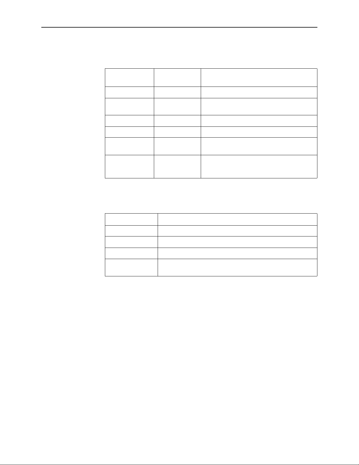
Document Summary
Section Description
Chapter 1,
Description
Chapter 2,
Screens
Chapter 3,
Chapter 4,
DSL System
Chapter 5,
Troubleshooting
Hotwire DSL System
Hotwire Menu s and
DSL Card Configuration
Monitoring the Hotwire
Diagnostics and
Hotwire Management
Provides an overview of the Hotwire DSLAM and
GranDSLAM systems.
Describes the operation of Hotwire menus,
screens, and commonly used navigation keys.
Also provides instructions on ho w to lo g in and l og
out of the system.
Describes procedures and contains tables for
configuring the DSL c ards o n the Hot wire syste m.
Describes operator programs that monitor the
Hotwire system.
Describes common Hotwi re ope ra tio nal problems
and solutions. Contains SYSLOG information.
Appendix A,
Appendix B,
Glossary
Index
Download Code
Traps
Describes how to work with the Download Code
and Apply Download menus.
Describes the traps that are generated by the
Hotwire system.
Defines acronyms and terms used in this
document.
Lists key terms, acronyms, concepts, and
sections in alphabetical order.
April 2001 8000-A2-GB26-50
vi
Page 9

Product-Related Documents
Document Number Document Title
About This Guide
5620-A2-GN10
6301-A2-GN10
6310-A2-GN10
6341-A2-GN10
6350-A2-GN10
6351-A2-GN10
6371-A2-GB20
6371-A2-GN10
7800-A2-GZ41
7800-A2-GZ42
Hotwire 5620 RTU Customer Premises Installation
Instructions
Hotwire 6301/6302 IDSL Routers Installation
Instructions
Hotwire 6310 MVL Modem Customer Premises
Installation Instructions
Hotwire 6341/6342 SDSL Routers Installation
Instructions
Hotwire 6350 ReachDSL Modem with Inline Phone
Filter Installation Instructions
Hotwire 6351 ReachDSL Router Installation
Instructions
Hotwire DSL Routers User’s Guide
Hotwire 6371 RADSL Router Installation Instructions
OpenLane 5.x Service Level Management for UNIX
Quick Start Installation Instructions
OpenLane 5.x Service Level Management for Windows
NT Quick Start Installation Instructions
8000-A2-GB22
8000-A2-GB25
8000-A2-GB90
8021-A2-GB20
8021-A2-GZ40
8303-A2-GZ40
8310-A2-GZ40
8312-A2-GZ40
8343-A2-GZ40
8373-A2-GZ40
Hotwire Management Communications Controller
(MCC) Card, IP Conservative, User’s Guide
Hotwire 8100/8200 Interworking Packet Concentrator
(IPC) Network Configuration Guide
Hotwire 8100/8200 Interworking Packet Concentrator
(IPC) User’s Guide
Hotwire Shelf Concentration Module (SCM) Card User’s
Guide
Hotwire Shelf Concentration Module (SCM) Card
Installation Instructions
Hotwire 8303/8304 IDSL Cards Installation Instructions
Hotwire 8310 MVL Card Installation Instructions
Hotwire 8312/8314 MVL and ReachDSL/MVL Cards
Installation Instructions
Hotwire 8343/8344 SDSL Cards Installation
Instructions
Hotwire 8373/8374 RADSL Cards Installation
Instructions
(Feature No. 8200-M2-901)
8000-A2-GB26-50 April 2001
vii
Page 10

About This Guide
Document Number Document Title
8510-A2-GZ40
8600-A2-GN20
Hotwire 8510 RADSL Card Installation Instructions
Hotwire 8600 Digital Subscriber Line Access
Multiplexer (DSLAM) Installation Guide
8610-A2-GN20
8620-A2-GN20
8800-A2-GN21
Hotwire 8610 DSLAM Installation Guide
Hotwire 8620 GranDSLAM Installation Guide
Hotwire 8800 Digital Subscriber Line Access
Multiplexer (DSLAM) Installation Guide
8810-A2-GN21
8820-A2-GN20
Contact your sales or service representative to order additional product
documentation.
Most Paradyne documents are also available on the World Wide Web at
www.paradyne.com
Hotwire 8810 DSLAM Installation Guide
Hotwire 8820 GranDSLAM Installation Guide
. Select
Library → Technical Manuals
.
April 2001 8000-A2-GB26-50
viii
Page 11
Hotwire DSL System Description
What is the Hotwire DSL System?
The Hotwire® Digital Subscriber Line (DSL) system is a set of central site products
that terminate and consolidate packet data traffic from many customers in a
serving area. The DSL card(s) then forwards the traffic to one or more network
access provider networks.
High-speed Internet and intranet access is either bridged or routed on the DSL line
cards and multiplexed over backbone networks. By enabling very high speeds
using DSL technology and concentrating Internet Protocol (IP) traffic, greater
performance is realized.
1
In addition, the Hotwire GranDSLAM, with an endpoint such as a 6310 Multiple
Virtual Lines (MVL
co-exist with plain old telephone service (POTS) over the same copper telephone
line, providing simultaneous usage of POTS and digital applications. That is, the
optional central office (CO) POTS splitter and customer premises POTS filter allow
simultaneous voice and data connections over a standard telephone line.
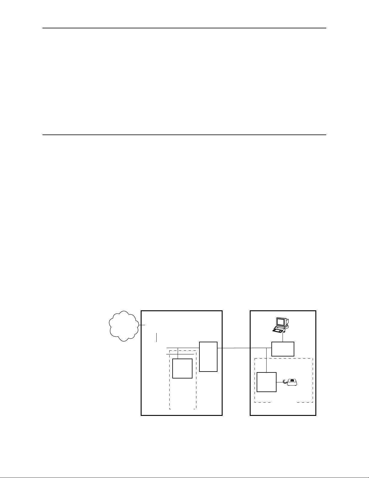
The
following illustration shows a typical configuration for a Hotwire 8610/8810
DSLAM chassis.
®
) modem and 5620 Remote Termination Unit (RTU), can
Central Office (CO)
Ethernet
DSL
CARD
DSLAM
CO
POTS
Splitter
MDF
Customer Premises (CP)
CP
POTS
Splitter
SN
Legend: DSL – Digital Subscriber Line IPC –Interworking Packet Concentrator
MDF – Main Distribution Frame POTS–Plain Old Telephone Service
SN – Service Node
8000-A2-GB26-50 April 2001
99-15674-03
1-1
Page 12
1. Hotwire DSL System Description
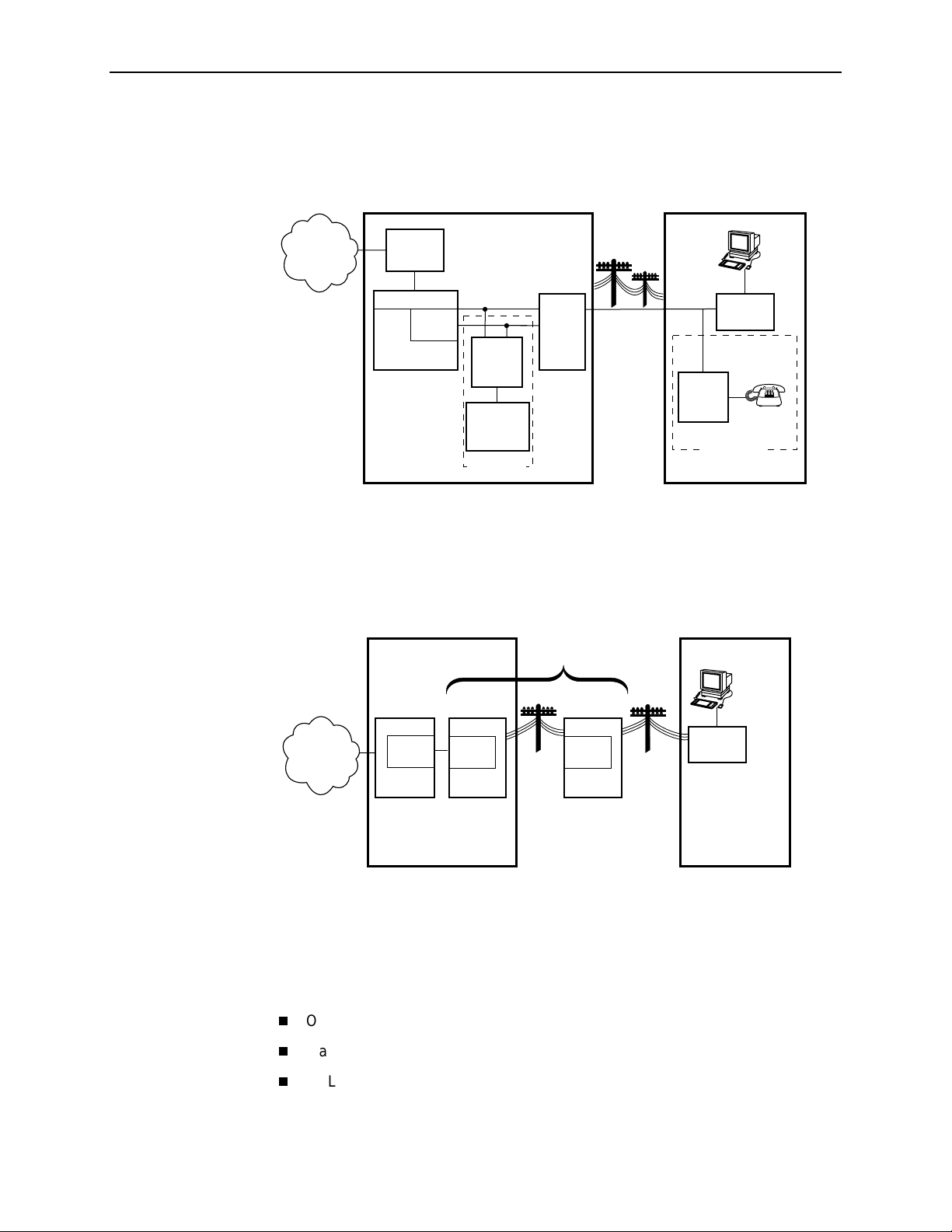
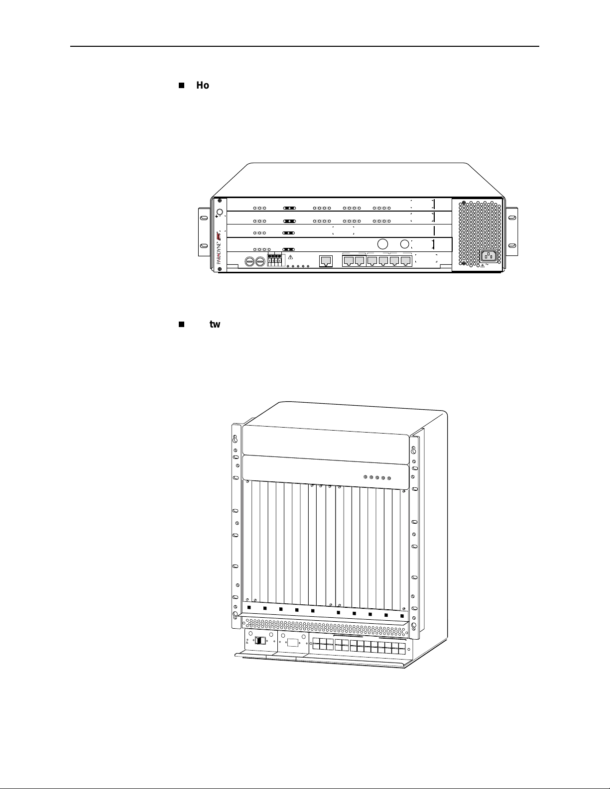
The following illustration shows a typical configuration for a Hotwire 8820
GranDSLAM chassis.
Central Office (CO)
Network
Service
Provider
Legend: DSL – Digital Subscriber Line IPC –Interworking Packet Concentrator
MDF – Main Distribution Frame POTS–Plain Old Telephone Service
SN – Service Node
Hotwire
IPC
ATM
SCM
DSL
CARD
GranDSLAM
CO
POTS
Splitter
Switched
Network
Optional
MDF
POTS/DSL
Customer Premises (CP)
Data
Interface
SN
POTS
Voice
Interface
CP
POTS
Splitter
Optional
00-16659
The following illustration shows a typical Hotwire configuration using IDSL cards.
Central Office (CO)
Digital Loop
Carrier (DLC)
Customer Premises (CP)
DSLAM
Network
Service
Provider
Legend: BRITE – Basic Rate Interface Transmission Extension
COT – Central Office Terminal
DSL – Digital Subscriber Line
RT – Remote T erminal
DSL
CARD
COT
BRITE
T1 or
Fiber
Channel
Bank
RT
BRITE
Twisted
Pair
Wire
Data
Interface
SN
00-16698-01
The minimum hardware requirements for a Hotwire DSL system consis ts of the
following components:
One Hotwire chassis
Management card(s)
DSL card(s)
April 2001 8000-A2-GB26-50
1-2
Page 13

Hotwire DSL System Components
The DSL system consists of a chas si s that hou ses a Manage men t
Communications Controller (MCC) card and up to 18 DSL cards. The Hotwire
8620 and 8820 GranDSLAM chassis can also house a Shelf Concentration
Module (SCM) card, depending on the application. See the
Concentration Module (SCM) Card User’s Guide
NOTE:
All references to MCC cards in this document refer to the MCC, MCP and
MCC Plus cards, unless specifically noted otherwise.
DSL Cards
DSL cards is a generic term used in this document for a variety of types of line
cards.
DSL line cards with an Ethernet uplink consist of the following:
1. Hotwire DSL System Description
Hotwire Shelf
for more information.
8303 24-port Integrated Services Digital Network Digital Subscriber Line
(IDSL) cards.
8310 4-port Multiple Virtual Lines (MVL) cards.
8510 4-port Rate Adaptive Digital Subscriber Line (RADSL) cards
8312 12-port MVL or ReachDSL/MVL cards.
8343 24-port Symmetric Digital Subscriber Line (SDSL) cards.
8373 12-port RADSL cards.
DSL line cards with an ATM uplink consist of the following:
8304 24-port IDSL cards.
8314 12-port MVL or ReachDSL/MVL cards.
8344 24-port SDSL cards.
8374 12-port RADSL cards.
In addition, the following cards are also supported in the Hotwire chassis:
Model 8335 and 8365 ATM Line cards.
Time Division Multiplexer Symmetric Digital Subscriber Line (TDM SDSL)
cards.
NOTE:
All references to DSL cards in this document refer to the RADSL, MVL,
ReachDSL/MVL, IDSL, and SDSL cards, unless specifically noted otherwise.
The ATM and TDM SDSL line cards are not within the scope of this document.
8000-A2-GB26-50 April 2001
1-3
Page 14
1. Hotwire DSL System Description
SCM Card
The Shelf Concentration Module (SCM) card aggregates DSL traffic for the
Hotwire 8620 and 8820 and GranDSLAM chassis. The operation and configuration
of this card is not within the scope of this document. See the
Concentration Module (SCM) Card User’s Guide
DSL Chassis
DSL cards can reside in four types of chassis:
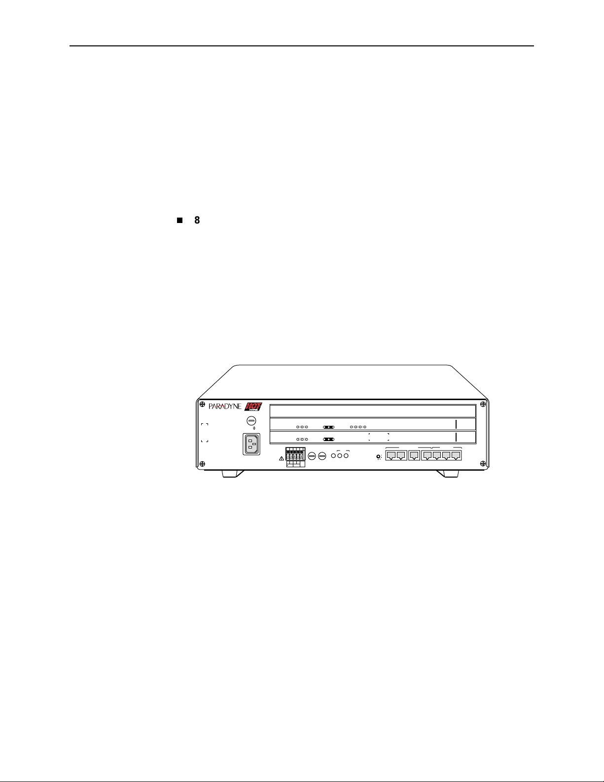
8600/8610 DSLAM
A 3-slot chassis with Ethernet uplink. The stackable design provides for up to
six chassis to share management access through a single MCC card, which in
turn allows an additional slot for a DSL card in each of up to five additional
chassis. The 8610 DSLAM chassis offers the same benefits as the
8600 chassis, with the added capability of accepting high-density DSL cards
(5–25 ports) such as the 8312 ReachDSL/MVL card. Management access is
through the Management Communications Processor (MCP) card. For more
information, see either the
Multiplexer (DSLAM) Installation Guide
Installation Guide
Hotwire Shelf
for more information.
Hotwire 8600 Digital Subscriber Line Access
Hotwire 8610 DSLAM
or the
.
8610
TM
ESDESD
AC
INPUT
TM
OK
Alrm
TestTXRX
Col1234
DSL PORT
ETHERNET
RX
Coll
TX
Test
ETHERNET
DC FUSES
T4A, MIN. 48V
A
PWR
FAN
ALM
B
A
B
3
2
POSITION
MANAGEMENT
5
6
4
1
STACK
OUTIN SERIAL
ALM INTF
10 BASE T
2
MCP/1
MCP/
DSL
48VDC CLASS 2
OR LIMITED
PWR SOURCE
SYSTEM
SYSTEM
48VARTN
Alrm
OK
ABB
3
2
8546
RADSL
1
8000
MCP
3
99-16311
April 2001 8000-A2-GB26-50
1-4
Page 15
1. Hotwire DSL System Description
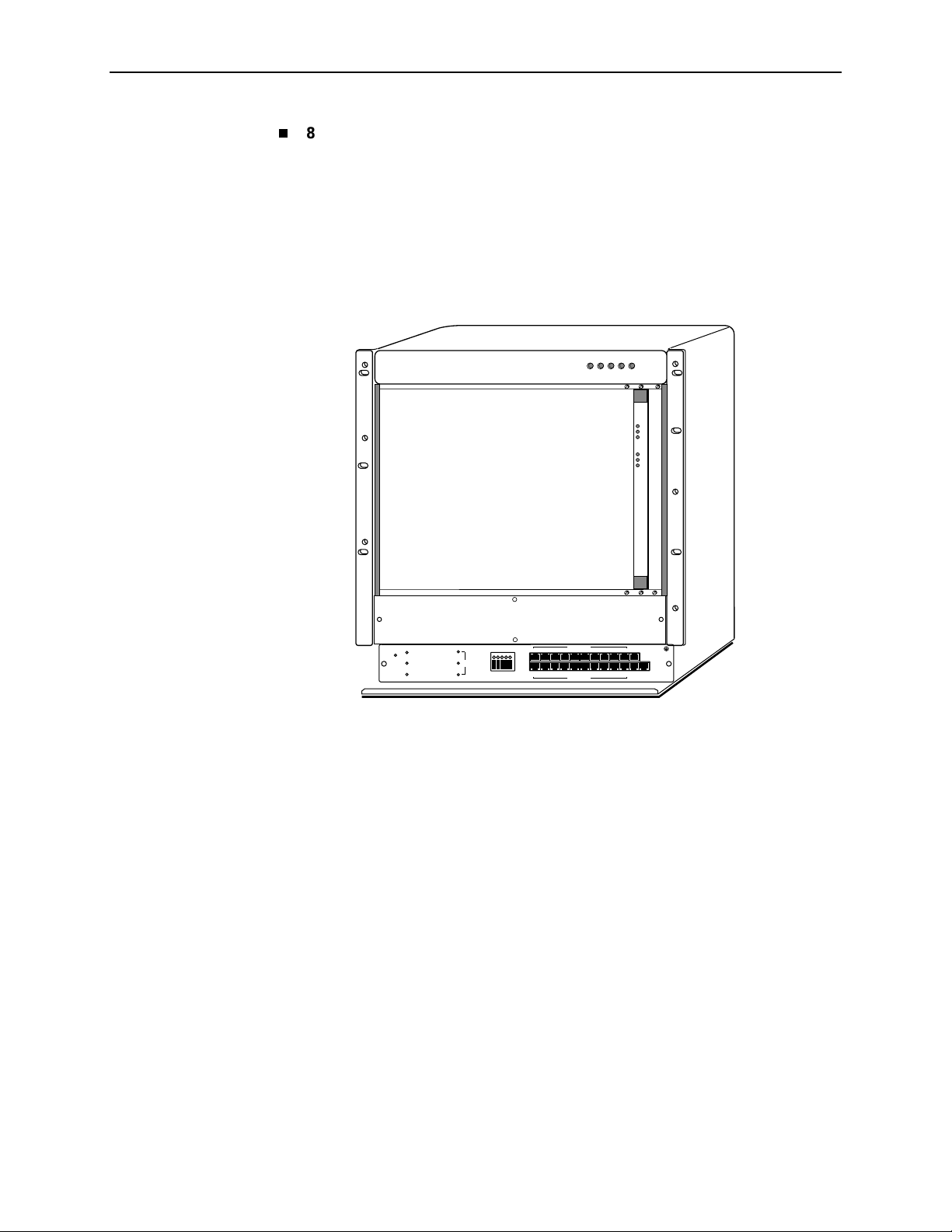
8800/8810 DSLAM
A 20-slot chassis with Ethernet uplink. These chassis are designed to house
up to eighteen DSL cards and one MCC card. (The remaining slot is reserved
for the future use of a redundant MCC card.) The Hotwire 8810 DSLAM
chassis is a higher density carrier for use with high-density line cards such as
the 8312 ReachDSL/MVL card, as well as lower density cards (4 ports or
less). For more information, see either the
Line Access Multiplexer (DSLAM) Installation Guide
DSLAM Installation Guide
.
Hotwire 8800 Digital Subscriber
Hotwire 8810
or the
ALARMS
POWER
Major MinorFanBA
SYSTEM
OK
Alm
Test
E
T
H
E
R
N
E
T
TX
RX
Coll
SLOTS 13-18
SLOTS 7-12
SLOTS 1 - 6
MCC
-48V INPUT
LINES
-48V (A)
-48V (B)
RET (A)
RET (B)
FR GND
LAN/WAN SLOT
101214
8
6
4
2
11
7
35
1
9
LAN/WAN SLOT
13 15
MGT
16
20
18
SERIAL
ALARM
19
17
MGT
10BT
99-15280-05
8000-A2-GB26-50 April 2001
1-5
Page 16
1. Hotwire DSL System Description
Hotwire 8620 GranDSLAM
A 4-slot chassis for Ethernet and/or ATM uplink. The Hotwire 8620
GranDSLAM supports up to two DSL cards, as well as an SCM card for
aggregating DSL traffic to an ATM uplink and an MCP card. For more
information, see the
Hotwire 8820 GranDSLAM
ESD
8620
GranDSLAM
SYSTEM
SYSTEM
SYSTEM
SYSTEM
DC FUSES
A
Hotwire 8620 GranDSLAM Installation Guide
RX
ATM B US
ATM B US
ETHERNET
Uplink Alrm
ETHERNET
-48V RTN
ABAB
LOC
TX
RX
TX
RX
TX
RX
TX
DC
POWER
AB
234
1
DSL PORT
LOC
123
4
DSL PORT
Coll
Coll
ALARM
ALARMS
M
M
A
I
F
J
N
A
O
O
N
R
R
91011
567
8
6789101112
5
CLOCK
SERIAL
AB
SCM MCP
12
TX
RX
LAN
SCM MCP
IP
IP
MCP
SCM-E3
MVL
MVL
10/100BT
SIM
8314
8314
8000
8025
SIM
Alrm
OK
Test
Alrm
OK
Test
Alrm
OK
Test
Alrm
OK
Test
B
.
3
2
1
A
AC INPUT
00-16894
A 20-slot chassis for Ethernet and/or ATM uplink. The Hotwire 8820
GranDSLAM supports up to 17 DSL cards, as well as an SCM card for
aggregating DSL traffic to an ATM uplink and an MCP card. For more
information, see the
MCP
Card
P
O
W
L
R
48V RTN
W
A
R
N
I
N
G
!
P
O
W
E
R
M
B
E
F
O
R
E
R
E
M
O
V
IN
G
O
Hotwire 8820 GranDSLAM Installation Guide
POWER
ALARMS
Major MinorFanBA
E
R
E
N
T
R
Y
M
O
D
U
L
E
E
F
T U
N
IT
: L
IN
E
A
IG
H
T
U
N
IT
: L
IN
E
B
48V NEG
48V RTN
U
S
T
B
E
D
IS
C
O
N
N
E
C
T
E
D
A
T
T
H
E
S
O
U
R
C
E
R
IN
S
W
T
A
A
L
R
L
N
IN
I
G
N
T
H
IS
P
W
R
E
N
T
R
Y
M
O
D
U
L
E
B
E
F
O
R
E
R
C
L
O
P
G
!
P
O
W
E
E
M
O
V
IN
C
O
R
R
M
G
O
K
W
E
R
L
E
F
IG
H
U
S
T
R
IN
S
E
T
T U
B
S
E
N
U
E
T
A
R
T
R
N
IT
N
IT
D
IS
L
L
I
A
Y
M
: L
IN
: L
C
O
IN
G
L
O
D
U
L
E
A
IN
E
B
N
N
E
C
T
E
T
H
IS
P
W
A
E
C
A
M
C
C
A
L
A
R
M
48V NEG
D
A
T
T
H
E
S
O
U
R
C
E
R
E
N
T
R
Y
M
O
D
U
L
E
B
S
E
R
I
A
L
A
L
A
R
M
C
L
O
C
K
S
M
C
M
2
1
4
35
L
A
N
/
W
A
N
S
L
O
T
6
8
A
1
0
1
2
1
4
1
6
1
8
7
9
B
1
1
1
3
1
5
1
7
.
00-16573-01
Front View of a Hotwire 8820 GranDSLAM Chassis
April 2001 8000-A2-GB26-50
1-6
Page 17

1. Hotwire DSL System Description
The DSL cards interoperate with the following types of Hotwire Service Nodes
(SNs)/endpoints to deliver applications at high speeds in support of packet
services over a DSL link:
The 8310 MVL card interoperates with the Hotwire 6310 MVL SN. The
8312/8314 ReachDSL/MVL cards interoperate with the Hotwire 6310 MVL SN
and the 6350 ReachDSL SN, as well as with the 6351 ReachDSL Router. The
8312/8314 cards running version 3.1 software will only interoperate with a
6310 SN running 3.1 software. The 8312/8314 cards running version 2.1
software will interoperate with a 6310 SN running either version 2.1 or 3.1
software.
The 8510/8373/8374 RADSL cards interoperate with the Hotwire 5620
RADSL SN and the 6371 RADSL DSL Router SN.
The 8303/8304 IDSL cards interoperate with the Hotwire 6301/6302 IDSL
Router SNs.
The 8343/8344 SDSL cards interoperate with the Hotwire 6341/6342 DSL
Router SNs.
Hotwire DSL System Features
The packet-based Hotwire DSL system contains the following features:
High-speed Internet or intranet access
RADSL ports (up to 7 Mbps)
MVL ports (up to 768 kbps)
IDSL ports (up to 144 kbps)
SDSL ports (up to 2320 kbps)
ReachDSL ports (up to 960 kbps )
Subscriber authentication, security access, and permission features that
prevent users from accessing unauthorized services
Diagnostic tests and performance capabilities
Primary network management support via SNMP agent for monitoring and
traps
Telnet for configuration and diagnostics
8000-A2-GB26-50 April 2001
1-7
Page 18

1. Hotwire DSL System Description
Configuring the DSL Cards
The Hotwire DSL software provides DSL configuration options to:
Configure the DSL cards
Configure the DSL port card at the physical port and logical interface levels
Configure a Service Node (SN)
Configure bridging information
Configure filters and associated rules
Upload or download a copy of a card’s configuration data to or from a Trivial
File Transfer Protocol (TFTP) server
Download a new version of the Access Node software
NOTE:
You must have Administrator permission to configure the system.
For more information about configuring the system, see Chapter 3,
Configuration.
DSL Card
April 2001 8000-A2-GB26-50
1-8
Page 19

Monitoring the DSL Cards
The Hotwire DSL software provides menu options to monitor the activity of the
Hotwire DSL cards. The monitoring screens allow you to:
List the status of active ports and interfaces in a card, as well as display
statistics about the physical layers and interfaces.
Display network protocol statistics, such as information about an application
program assigned to a specific socket number, UDP statistics, TCP data and
connection statistics, IP statistics, ICMP packet statistics, and SNMP statistics
including SNMP authentication statistics.
Display information about the Client, ARP, and Virtual Network Identifiers
(VNIDs).
Display endpoint information about DSL ports such as Service Node type,
system name, system contact, and system location. Model and serial number,
along with firmware and hardware revisions, are also shown.
Use the monitoring screens to help you gather pertinent information and isolate
potential problem areas. You can monitor the system with either Administrator or
Operator permission. For more information about monitoring the system, see
Chapter 4,
Monitoring the Hotwire DSL System.
1. Hotwire DSL System Description
Troubleshooting and Diagnostics
The Hotwire DSL system provides DSL diagnostic menu options, for example,
that:
Display self-test results for CPU health, memory and ports, and reset time.
Show major alarms such as Selftest Failure, Processor Failure, and DSL or
Ethernet port failure.
Show minor alarms such as Configuration Error or Incorrect SN ports.
Run a nondisruptive packet echo test over the DSL line.
NOTE:
You must have Administrator permission to perform most of the
troubleshooting and diagnostic activities. However, you can run nondisruptive
tests as a user with Operator permission.
For more information about troubleshooting and diagnostics, see Chapter 5,
Diagnostics and Troubleshooting.
NOTE:
If you would like more information on DSL-based services, applications, and
network deployment, refer to Paradyne’s
downloaded or ordered through Paradyne’s World Wide Web site at
www.paradyne.com
8000-A2-GB26-50 April 2001
.
DSL Sourcebook.
The book may be
1-9
Page 20

1. Hotwire DSL System Description
April 2001 8000-A2-GB26-50
1-10
Page 21

Hotwire Menus and Screens
Menu and Screen Formats
The Hotwire DSL system has an ASCII-based menu- and screen-driven user
interface system that enables the user to configure and monitor the Hotwire cards.
This section describes the components of a typical Hotwire menu and screen.
Components of a Hotwire Menu
A typical Hotwire menu format is shown below:
2
1
2
3
Menu Title
1.
menu or submenu.
Menu List
2.
options. When selected, a menu option displays a submenu window or screen.
Letter Navigation Ke ys
3.
convenient way (shortcut) to select a menu item.
For example, from the Hotwire – DSL menu illustrated above, you can simply
press the A key to select the Configuration menu item. The Configuration
menu appears. You can then press the A key to select the Card Status menu
item. This action displays the Card Status menu. (You can also use the arrow
keys on your keyboard to select a menu item. See
Keys
on page 2-4 for more information.)
is the top line of the menu window that displays the title of the
is the portion of the menu window that displays the list of menu
are provided within a menu list. These keys provide a
Commonly Us ed Na vigati on
8000-A2-GB26-50 April 2001
2-1
Page 22
2. Hotwire Menus and Screens
Components of a Hotwire Screen
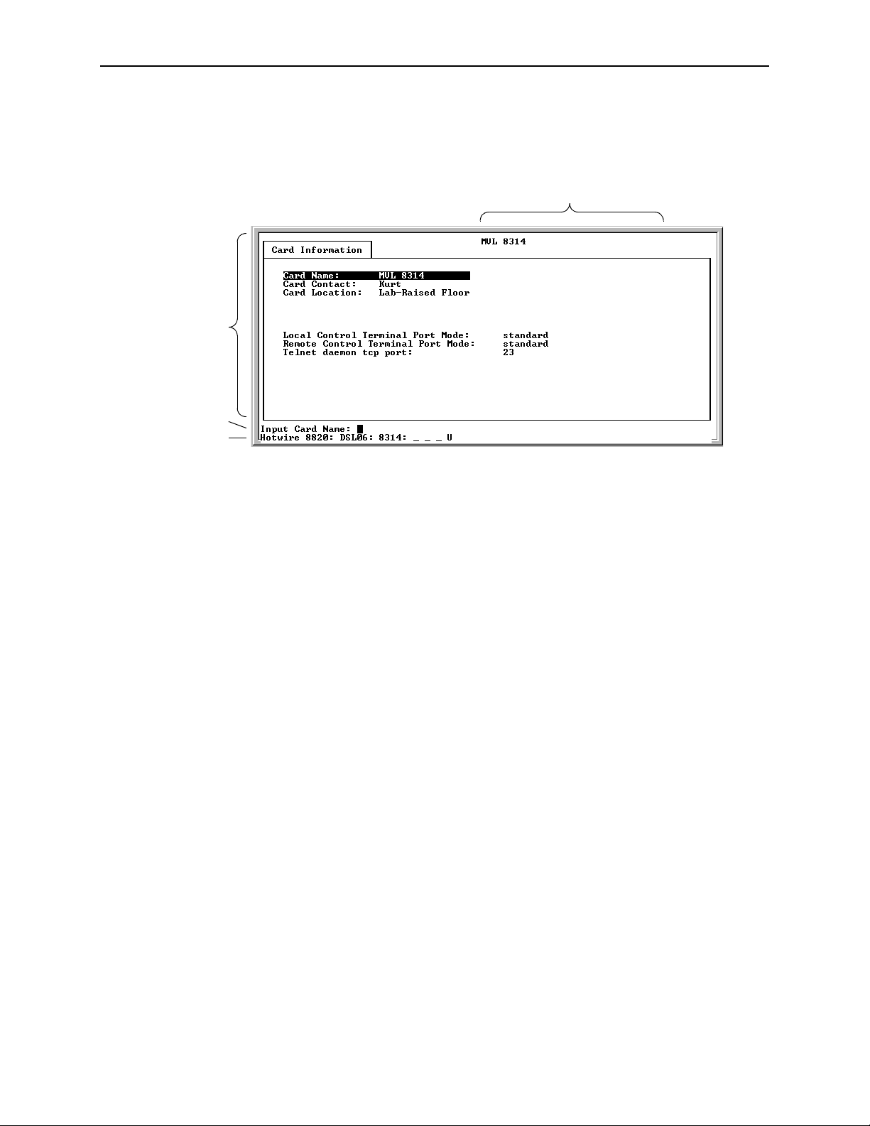
A typical Hotwire screen looks like this:
2
3
4
1
System Header Line
1.
is the top line of the screen. This line has two fields that
provide system login information.
— The first field displays the system name or the individual card name.
(Access the System Information screen by selecting the appropriate card
in the chassis and then follow this menu sequence:
→
Status
interface will display
Card Info
.) If you do not define the system name, the DSL user
<no name>
.
Configuration→Card
— The second field displays the current login.
Display Area
2.
is the top portion of the screen on which pertinent DSL system
information is displayed. This is also the portion of the screen on which fields
requiring input are displayed. However, you cannot enter values for the fields
in this portion of the screen. You must enter field values in the Input Line at the
bottom of the screen (see Step 3).
Input Line
3.
is the area of the screen below the line where you are prompted to
enter values for the specific field that is highlighted on the screen.
For example, in the General Interfaces screen above, the Interface Name field
is highlighted. If you want to modify an interface, you must enter the Interface
Name at the
Input Interface Name:
prompt at the bottom of the screen.
April 2001 8000-A2-GB26-50
2-2
Page 23

2. Hotwire Menus and Screens
Status Line
4.
is the last line of each user interface screen that contains status
information for the port card currently selected. Status information is the same
as what is reported on the card selection screens, including the following:
— Chassis type (8810, etc.)
— Interface type (DSL, etc.)
— Number of interfaces (01–24, depending on number of ports available for
selected card)
— Status of each interface
For cards with more than 12 ports, the following two lines will alternately
appear each time the screen is refreshed:
Line 1:
Hotwire 8810: DSL01: 8343 _ M _ D U
Line 2:
DSL01: 8x43 UUDDX XXXXX XXXXX XXXXX XXXX
For more information about the status displayed on this screen, such as major
and minor alarms, see
Troubleshooting
in Chapter 5,
Diagnostics and
Troubleshooting.
8000-A2-GB26-50 April 2001
2-3
Page 24

2. Hotwire Menus and Screens
Commonly Used Nav i gation Keys
The following table lists navigation keys and their definitions. These commands
are used to move around the Hotwire DSL menus and screens.
Keys Definition
Backspace, Del,
Ctrl-d
Ctrl-e Returns to the card selection screen from any screen.
Ctrl-r Resets counters (on monitoring statistics displays).
Ctrl-u Clears the current input or prompt line.
Esc h, ? Displays the online Help screen.
Ctrl-v Displays pop-up menus.
Esc l, Ctrl-l Refreshes the screen.
Esc n Goes to the next window.
Esc p, Ctrl-z Goes back to the previous window.
Esc t, Ctrl-a, Ctrl-c,
Ctrl-t, or Ctrl-y
Left arrow, Ctrl-b Moves the cursor to the left.
Right arrow, Ctrl-f Moves the cursor to the right.
Up arrow, Ctrl-p Moves up to the previous menu selection or entry field.
Down arrow, Ctrl-n Moves down or to the next selection.
Enter or Return Accepts entry.
Erases the character to the left of the prompt.
Goes back to the original, top-level window.
April 2001 8000-A2-GB26-50
2-4
Page 25

Levels of Access
2. Hotwire Menus and Screens
There are two levels of privileges on the Hotwire DSL system. Your user accounts
can be configured with a user name, password, and privilege of:
Administrator
system. With Administrator permission, you can set specific parameters and
variables to configure cards, ports, interfaces, VNID bridging, and endpoint
selection.
Operator
information and monitor performance but has no configuration menu access or
modification permission.
The default access is no login and password with Administrator status. To provide
login security to the DSL system, user accounts must be configured.
. The Administrator has complete read/write access to the DSL
. The Operator has read-only access and can view configuration
NOTE:
There must be at least one Administrator configured in order to have system
security.
For information on configuring user accounts, see the
Communications Controller (MCC) Card, IP Conservative, User’s Guide.
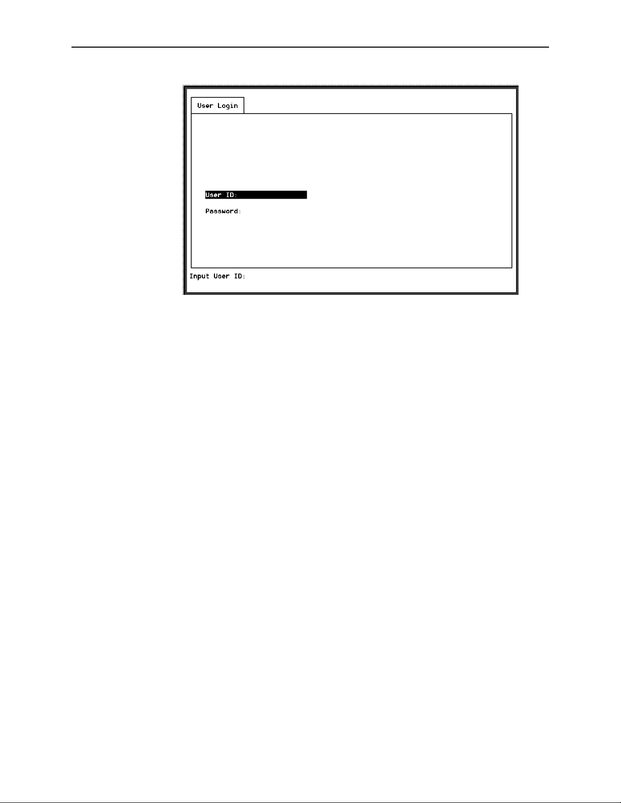
User Login Screen
You can log in to the Hotwire DSL system using either a local VT100-compatible
terminal or a remote Telnet connection. However, the Hotwire DSL system accepts
only one login session at a time.
At the User Login screen, enter your login ID and password. You must wait until
your login is verified, anywhere from two seconds to 12 minutes. If you have
RADIUS Authentication, this verification takes some time while each RADIUS
server is contacted one at a time.
If you are denied access during a T elnet session, the session stops and an error is
logged. If you are using a console, return to the User Login screen.
Hotwire Management
NOTE:
The User Login screen only appears if one or more users have been defined
on the MCC.
NOTE:
If you forget your password, contact your Technical Service Center. Have the
serial number of the MCC card available, and the service representative will
provide you with a password.
8000-A2-GB26-50 April 2001
2-5
Page 26
2. Hotwire Menus and Screens
NOTE:
The login ID and password are case-sensitive; that is, the system recognizes
both upper- and lowercase letters. For example, if you enter your user name
and password information in uppercase letters and your assigned user name
and password are in upper- and lowercase letters, the system will not let you
log in.
After entering your login ID and password, the system displays the Hotwire
Chassis Main Menu.
April 2001 8000-A2-GB26-50
2-6
Page 27
Hotwire Menu Hierarchy
This section describes the menu structure of the Hotwire user interface.
NOTE:
The Hotwire menu for the line cards with an ATM Network interface (used in
conjunction with the SCM card) has a few differences from the other DSL port
card menus. For example, the menu for line cards with an ATM Network
interface will show SAR Statistics while other line cards will show Ethernet
Statistics for menu selection
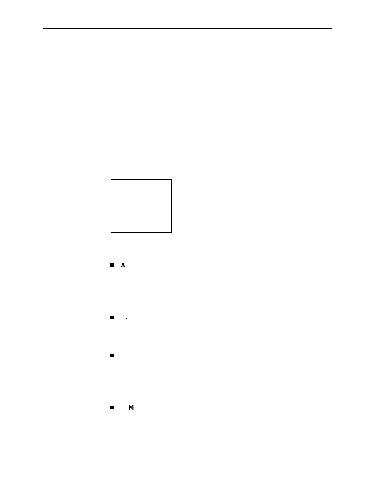
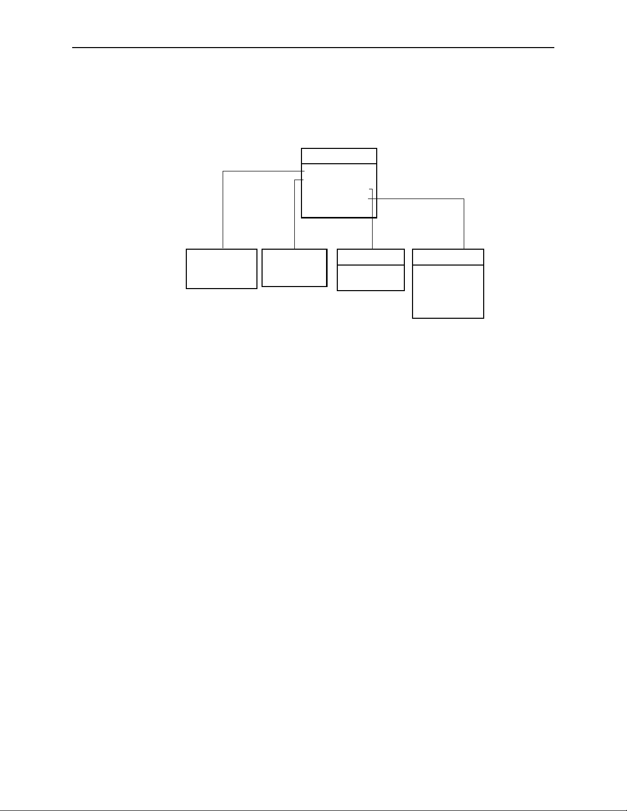
Hotwire Chassis Main Menu
The following illustration shows the Hotwire Chassis Main Menu.
Hotwire Chassis
A.Quick Card Select
B.Port Card Select
C.Mgmt. Card Select
D.Managed SN Select
E.Chassis Info
F. Current Users
G.Logout
00-15566-03
B-B-B
2. Hotwire Menus and Screens
.
From the Hotwire Chassis Main Menu, you can select:
A. Quick Card Select
to displa y a list of all ca rds in th e chass is . Used to jump
directly to an MCC, SCM or DSL card in the chassis, or to a Service Node
(SN). The card you select determines the next Hotwire menu. Also provides
status on the card interfaces. After selecting a port card or SN, you can return
to the Quick Card Select screen by pressing Ctrl-e.
Quick Card Select Screen
See
B. Port Card Select
to select a particular port card in the chassis or display
on page 2-8.
status about all port cards and their interfaces. After selecting a port card, you
can return to the Port Card Select screen by pressing Ctrl-e.
Port Card Select Screen
See
C. Mgmt. Card Select
on page 2-8.
to select a particular management card in the chassis
or display status about all management cards and their interfaces. After
selecting a management card, you can return to the Mgmt. Card Select screen
by pressing Ctrl-e.
See the
Conservative, User’s Guide
D. Managed SN Select
Hotwire Management Communications Controller (MCC) Card, IP
for more information about the MCC card menu.
to display the list of directly managed SNs and their
connectivity status. After selecting a SN, you can return to the Managed SN
Select screen by pressing Ctrl-e.
See the
Hotwire DSL Routers User’s Guide
menu.
8000-A2-GB26-50 April 2001
for more information about the SN
2-7
Page 28

2. Hotwire Menus and Screens
E. Chassis Info
name, person responsible for the system, and physical location.
Chassis Information Screen
See
F. Current Users
Current Users Screen
See
G. Logout
to enter or display chassis information, such as the chassis
on page 2-9.
to view a list of the users currently logged in to the chassis.
on page 2-9.
to exit from the current login session on the Hotwire DSL system.
Quick Card Select Screen
This screen displays all the cards in the chassis and enables you to Telnet to a
selected card in the chassis or to a connected DSL Router, providing you know the
port on the DSL card to which the endpoint is connected. Select a specific card or
SN and establish a connection from it to the MCC for configuring or monitoring the
card. Only those slots that are populated are displayed; empty slot numbers are
skipped. If more than 17 slots are populated, 15 cards will display on a first page,
with the remaining slots displaying on a second page.
Port Card Select Screen
For more information, see
Exiting from the System
on page 2-16.
NOTE:
If a card is locked in Download Only mode, you will be informed of this and no
status will display on the screen.
April 2001 8000-A2-GB26-50
2-8
Page 29
Chassis Information Screen
Field
Chassis Name 16 alphanumeric Name for the equipment.
Chassis Contact 32 alphanumeric Name and phone number of individual
Chassis Location 16 alphanumeric Physical location of the equipment.
Bay Number 16 alphanumeric Floor and/o r bay number of the equipment.
Chassis Number 16 alphanumeric Chassis serial number (located on the lower
Chassis Model 4 alphanumeric Chassis model number (8600, 8800, 8610,
2. Hotwire Menus and Screens
Input
Characters Description
responsible for the equipment.
right side of chassis).
8810, or 8820). The MCC card fills in this field,
but you can change it.
Current Users Screen
Field Description
User ID User ID of the person logged in.
Time Login time.
Priv Access level assigned to the user who logged in.
Console/Telnet/FTP The type of login (C, T, or F). If Telnet (T) or FTP (F), the IP
address of the remote host is also recorded.
8000-A2-GB26-50 April 2001
2-9
Page 30
2. Hotwire Menus and Screens
Hotwire – DSL Menu
After selecting a specific DSL card from either the Quick Card Select screen or the
Port Card Select screen, the DSL system displays the Hotwire – DSL Menu.
Hotwire – DSL
A. Configuration
1
B. Monitoring
C. Applications
D. Diagnostics
E. Exit
See
Configuration
Menu
1
See
Monitoring
Menu
Applications
Function
not Supported
Diagnostics
A.Selftest
B.Alarms
C. Packet Echo
1
The Configuration menu item appears only if
you have Administrator permission.
D. SN Selftest
E. BERT
01-15975-05
From this menu, you can configure, monitor, and troubleshoot a specific DSL card.
April 2001 8000-A2-GB26-50
2-10
Page 31

DSL Card Configuration Menu
The following figure illustrates the complete Configuration menu hierarchy from the
Hotwire – DSL menu.
2. Hotwire Menus and Screens
(A) Configuration
A. Card
B. Ports
C. Interfaces
D. Users
E. Bridge
F. SN Configuration
G.Filters
(F) SN Configuration
(G) Filters
A. IP Filters
B. Ethertype
Filters
(F) ARP
A. Parameters
B. ARP Entry
1
(D) Users
Function Not
Supported
(B) Ports
A. Ethernet P ort
B. DSL Ports
(A) Card
A. Card Info
B. Time/Date
C.NVRAM Clear
D.NVRAM Cfg Loader
E. Card Reset
F. Download Code
(F) Download Code
A. Download Code
B. Apply Download
1
DSL Card with Ethernet Network Interface only
(C) Interfaces
A. General
B. Control
(E) Bridge
A. General
B. Card VNID Tab le
C. VNID Binding Table
D. Client Allocation
E. Client VNID Tab le
F. ARP T ab le
NOTE:
The Configuration menu and its submenus appear only when logging in to the
system with a user account that has Administrator permission.
01-15899-06
Use care when entering configuration information, since the system will react
based on the values you enter. Entering configuration information may result in
adding data in the MIB II Systems Group.
8000-A2-GB26-50 April 2001
2-11
Page 32

2. Hotwire Menus and Screens
DSL Card Monitoring Menu
The following figure illustrates the complete Monitoring menu hierarchy from the
Hotwire – DSL menu.
(B) Monitoring
A. Card
B. Physical Layer
C. Interfaces
D. Network Protocol
E. Bridge
F. SN Information
G. Filters
(A) Card
A. Card Info
B. Login History
C. Syslog
(B) Physical Layer
A. Active List
B. Ethernet Stats
B. SAR Stats
C. EtherHDLC Stats
D. DSL Link Perf
E. DSL Perf Stats
F. DSL Error Stats
G. DSL Xmit Stats
1
DSL Card with Ethernet Network Interface only
2
DSL Card with ATM Network Interface only
Logging In to the System
This section describes how to log in to the Hotwire DSL system after the system
has been configured. For information on accessing the system for the first time,
see the
Conservative, User’s Guide.
Hotwire Management Communications Controller (MCC) Card, IP
(C) Interfaces
A. Active List
B. Status
(E) Bridge
A. Card VNID Tab le
1
2
B. MAC T able
C.VNID Binding Table
D.Client Allocation
E. Client VNID Tab le
F. ARP Tab le
(F) SN Information
(G) Filters
A. IP Filters
B. Ethertype
Filters
01-15900-08
NOTE:
When you power on the system for the first time, the system displays the Who
Am I screen. This screen can be accessed only from the local console.
April 2001 8000-A2-GB26-50
2-12
Page 33

Accessing a Selection Screen
Procedure
To access one of the selection screens:
1. From the Hotwire Chassis Main Menu, select one of the following:
—A for Quick Card Select
—B for Port Card Select
—C for Mgmt. Card Select
—D for Managed SN Select
The desired selection screen appears.
2. Hotwire Menus and Screens
2. At the
Goto:
prompt, type the slot number of the desired card. Or, type the
slot and port number of the desired SN.
The appropriate menu appears. For Management card menu information, see
Hotwire Management Communications Controller (MCC) Card, IP
the
Conservative, User’s Guide
Routers User’s Guide
The following is an example of the Port Card Select screen.
. For SN menu information, see the
.
Hotwire DSL
NOTE:
If an option is not active, an underscore appears in its place.
8000-A2-GB26-50 April 2001
2-13
Page 34

2. Hotwire Menus and Screens
The following information is displayed on the Port Card Select screen.
Column
Heading Display Description
Slot <slot number > Slot number of card in cha s sis.
Card <card type> Model number of card such as 8510, 8312,
8343, etc.
Type
(1st line)
Status
(1st line)
Type
(2nd line)
Status
(2nd line)
Type
(3rd line)
Status
(3rd line)
PC Stat Port card status.
Position 1: T or _ Test mode. Card currently in test mode or _ for
no active test.
Position 2: M or _ Major alarm. Major alarm present on card or _
for no active major alarm.
Position 3: R or _ Minor alarm. Minor alarm present on card or _
for no minor alarm active.
<descriptive text> Up to 42 characters of additional information
about the card (IP Conservative soft ware) and
status of the card (Active or Spare).
RADSL, MVL, SDSL, etc.
(1–24)
<port status> Port status: U=Up, D=Down, X=Disabled/Not
Eth, etc. (1) Uplink type (number of ports).
<uplink status> Status of uplink:
DSL type (number of ports).
Initialized
U=Up, D=Down, X=Disabled/Not Initialized,
L=Loopback, A=Alarm
For example, the following may be displayed on the Port Card Select screen:
Position:
Line 1:
Line 2:
Line 3:
1 2
3
1: 8510 PC Status _ _ _ 10bT
RADSL(4) U D D D
Eth(1) U
This display shows the following:
There is an 8510 port card with a 10 BaseT interface in Slot 1
— Position 1 – No current test ( _ )
— Position 2 – No major alarm is present ( _ )
— Position 3 – No minor alarm present ( _ )
This RADSL card has four ports. Port 1 is up, while Ports 2 through 4 are
down.
There is an Ethernet uplink (one port) and the link is up.
April 2001 8000-A2-GB26-50
2-14
Page 35

2. Hotwire Menus and Screens
The following is an example of the Quick Card Select screen.
NOTE:
If an option is not active, an underscore appears in its place.
The following information is displayed on the Quick Card Select screen.
Column
Heading Display Description
Slot <slot number> Slot number of card in chas sis.
Card <model number> Model number of card such as 8510, 8312,
8343, etc.
Type RADSL, MVL, SDSL, etc.
(1–24)
Status Positio n 1: T or _ Test mode. Card c urrently in test mode or _ for
Positio n 2: M or _ Major alarm. Major alarm present on card or _
Positio n 3: R or _ Minor alarm. Minor alarm present on card or _
UpLinks <uplink sta t us > Status of uplink:
ATM <atm status> Status of ATM uplink:
Card type (number of ports), for example
MVL(12).
no active test.
for no active major alarm.
for no minor alarm active.
U=Up, D=Down, X=Disabled/Not Initialized,
L=Loopback, A=Alarm
U=Up, D=Down
Links <dsllink status> Status of DSL ports:
8000-A2-GB26-50 April 2001
U=Up, D=Down, X=Disabled/Not Initialized,
I=Incompatible slot, H=Handshaking,
E=Empty slot, N=Network timing
2-15
Page 36

2. Hotwire Menus and Screens
Accessing the Hotwire – DSL Menu
Procedure
To access the Hotwire – DSL menu:
1. From the Hotwire Chassis Main Menu, select one of the following:
—A for Quick Card Select
—B for Port Card Select
The desired selection screen appears.
2. Verify that the DSL card you want to access appears on the selection screen.
3. At the
Goto:
you want to configure the DSL card in Slot 13, type 13. Then, press Enter.
The Hotwire – DSL menu appears.
Exiting from the System
You can manually log out of the system or, after five minutes (on MCC or SCM) or
ten minutes (on Access Node) of inactivity, the system will automatically log you
out.
Manually Logging Out
Procedure
To exit from the Hotwire DSL system:
1. Return to the card selecti on sc reen by select ing Exit from the Hotwi re – DSL
menu.
2. Press Ctrl-z.
3. From the Hotwire Chassis Main Menu, select Logout.
prompt, type the slot number of the desired card. For example, if
The system exits from the current login session on the Hotwire DSL system.
Automatically Logging Out
The DSL system has an automatic timeout feature that logs you out of the system
after five minutes (on MCC or SCM) or ten minutes (on Access Node) of inactivity.
You will need to log back in to continue your work.
To log back in, press Enter to display the User Login screen and log in.
April 2001 8000-A2-GB26-50
2-16
Page 37

DSL Card Configuration
Overview
This chapter describes configuration options on the DSL card. Use these options
to customize your applications. For information on customizing the MCC card, see
Hotwire Management Communications Controller (MCC) Card, IP
the
Conservative, User’s Guide.
Naming Conventions
Special naming conventions exist for the Port Name and Interface Name fields.
3
Port Name
dsl for a DSL card, eth for Ethernet, or sar for SAR), and a port number. The
port number can range from 1–4 for 4-port cards such as the 8510 RADSL
card, 1–12 for 12-port cards such as the 8312 ReachDSL/MVL card, or 1–24
for 24-port cards such as the 8343 SDSL card. See the following example:
dsl4
where:
dsl
4
Interface Name
and a port number (same as the port name), followed by a number identifying
the drop on which the connection is located (for those networks consisting of
multiple drops on a line). Currently, the drop number is limited to 1 on all
screens, except for Block Erro r Rate Test (
card. See the following example:
dsl12:1
where:
dsl
12
– Identifies a physical port. It consists of a family name (such as
= Family Name (dsl, eth or sar)
= Port Number (for example, Port 4)
– Identifies a logical connection. It consists of a family name
D-E
) on the 8314 ReachDSL/MVL
= Family Name (dsl or eth)
= Port Number (for example, Port 12)
1
= Multidrop Number (currently, only 1 is allowed)
8000-A2-GB26-50 April 2001
3-1
Page 38

3. DSL Card Configuration
Configuring Subnet Addressing
To define a subnet entry, the IP address has to be entered as the lower boundary
address of the subnet. Otherwise, only a host entry can be configured.
For example, a subnet with a mask of 255.255.255.192 requires one of the
following IP addresses, where
xxx.xxx.xxx
xxx.xxx.xxx
xxx.xxx.xxx
xxx.xxx.xxx
Configuring Subnet Masks
After the IP address is entered, a default subnet mask is displayed. The default
subnet mask is based on the IP address entered and can be changed.
If the IP Address entered is . . . Then the Default Subnet Mask is . . .
.0
.64
.128
.192
xxx
= any IP address:
xxx.xxx.xxx.
xxx.xxx.
xxx.
0.0.0 255.0.0.0
xxx.xxx.xxx.xxx
0 255.255.255.0
0.0 255.255.0.0
255.255.255.255
To configure the DSL card, a valid subnet must be used. When a Host entry is
input, any valid IP address results in a subnet mask of 255.255.255.255.
When a Subnet entry is entered, the valid subnet mask is based on the IP address
entered. A valid subnet mask must be in one of the following formats:
255.0.0.0
nnn.
255.
255.255.
0.0
nnn.
255.255.255.
Where
nnn
must be: 0, 128, 192, 224, 240, 248, 252, 254.
0
nnn
April 2001 8000-A2-GB26-50
3-2
Page 39

Domain Types
Service Domain
Management Domain
3. DSL Card Configuration
To monitor and control the overall system, the Hotwire Access Network should be
partitione d into two distinc t domai ns :
Service domain(s) (Layer 2, MAC Bridging)
Management domain (Layer 3, IP Routing)
A service (or data) domain is comprised of all clients and servers (grouped
physically or virtually) that communicate across a common WAN or LAN
connection for Internet or intranet access. This is the Layer 2 bridging domain of
the NSP. The Access Node cards and the Service Nodes are the Hotwire
components of this domain. The service domain also encompasses an NSP and
all end-user systems that subscribe to that NSP.
The primary function of the management domain is monitoring and configuring the
DSL cards and service domains served by the DSLAM. The management domain
should reside in a mutually exclusive domain from that of the service (data)
domain(s). The MCC card functions as a service router and is the primary tool for
configuring and diagno si ng the man agem ent domai n.
It is recommended that the management domain reside in a separate domain from
the service domain(s) for security purposes and to improve download
performance.
Minimum Configuration
The minimum configuration of the DSL port card differs, depending on the type of
SN used.
Minimum Configuration When Using the 5620, 6310, or 6350 SN
When using either the 5620, 6310, or 6350 SN, the DSL port card is in control of
the connection. At a minimum, you must configure the following:
VNIDs on a DSL card (see
The active VNID and the Next Hop Router on each DSL port/interface (see
Configuring the Active VNID and the Next Hop Router on each DSL
Port/Interface
on page 3-22) when using DHCP
Configuring VNID(s) on a DSL Card
on page 3-20)
Static users (see
users on your network, fixed addresses, or subnets
8000-A2-GB26-50 April 2001
Configuring Static Users
on page 3-23) if you have static
3-3
Page 40

3. DSL Card Configuration
Minimum Configuration When Using the DSL Router
When using the DSL Router as the SN, the DSL Router is in control of the
connection. At a minimum, you must configure the following:
VNIDs on a DSL card (see
Activate the VNID Binding Table to the port (see
and the Next Hop Router on each DSL Port/Interface
when using a DSL card with an ATM Network interface in Standard mode.
NOTE:
The default minimum configuration for a DSL card with an ATM Network
interface is a valid configuration.
DSL Configuration Card Screens
Use the system information submenu of the Card screens to configure basic DSL
card-level information.
Configuring VNID(s) on a DSL Card
Configuring the Active VNID
on page 3-22), except
on page 3-20)
NOTES:
— Only a user who logs in to the Hotwire DSL system with Administrator
permission can configure the DSL card.
— You cannot upload a configuration from a 4-port MVL card, then download
it to an 8312 12-port ReachDSL/MVL card.
April 2001 8000-A2-GB26-50
3-4
Page 41

3. DSL Card Configuration
Procedure
To configure card information, time/date, clear NVRAM, upload or download
configuration sets, download new firmware, or reset card:
1. Follow this menu selection sequence:
Configuration→Card
(
A-A
)
2. The Card menu appears. Enter the desired value on each selected screen and
field as s hown in Table 3-1, Card Options, and press Enter.
Table 3-1. Card Options (1 of 3)
Card Info (Card Information) A-A-A
Gives the user the ability to configure basic card-level information.
Card Name
(Default = noname).
Card Contact
responsible for the card (Default = nobody).
Card Location
(Default = nowhere).
Local Control Terminal Port Mode
(for European keyboards).
Remote Control Terminal Port Mode
Extended (for Europea n keyboards).
Telnet daemon tcp port
listens on. This field is read-only.
Time/Date A-A-B
– 16 alphanumeric characters maximum. Name assigned to the DSL card
– 32 alphanumeric characters maximum. Name or number of party
– 16 alphanumeric characters maximum. Location of the card
– Either Standard (for USA keyboards) or Extended
– Either Standard (for USA keyboards) or
– Displays 23. The TCP port number that the Telnet daemon
Displays the time zone, local time, and date on the DSL card.
Time zone
Local Time/Date
(Default = none).
NOTE: At system boot time and then periodically, the time zone, local time, and date
on the DSL cards automatically synchronize with the MCC card.
NVRAM Clear A-A-C
Clears out the Non-Volatile RAM (NVRAM) and returns the configuration to factory
defaults. This is useful if you want to reuse or reconfigure the card.
CAUTION: If you select yes on this screen, you will permanently remove all of the
configuration in f o rmation y ou ha ve stored on this card. The sy st em will perf orm a reset
and return the card to its factory configuration.
– Name of the system’s time zone (Default = GMT).
– Time in
hh:mm
format (am or pm). Date in
mm/dd/yy
format
8000-A2-GB26-50 April 2001
3-5
Page 42

3. DSL Card Configuration
NVRAM Cfg Loader (NVRAM Configuration Loader) A-A-D
Provides the ability to upload or dow nload a co py of t he card ’s binary configuration data to
or from a Trivial File Transfer Protocol (TFTP) server.
Configuration File Name
directory names separated by a forward slash (/) end ing with the file name . The tot al pa th
name length must be less than 40 characters. If the TFTP server is hosted by a DOS
machine running other than Windo ws 2000 or Wi ndo ws NT, then directory and file names
must follow the 8.3 DOS namin g convention.
DOS Machine
– The file name may be a regular path name expression of
April 2001 8000-A2-GB26-50
3-6
Page 43

3. DSL Card Configuration
Table 3-1. Card Options (3 of 3)
Download Code (Download Code and Apply Download) A-A-F (A and B)
Provides the ability to download a new version of code and apply the downloaded code.
For further information on this feature, see Appendix A,
Select
Download Code (A) or Apply Download (B).
the Apply Download screen.
Download Code (A)
Allows code download. This screen is sim il ar t o the NVRAM Configuration Lo ade r s cre en
(
).
A-A-D
Image File Name
names separated by a forward slash (/) ending with the file name. The total path name
length must be less than 40 characters. If the TFTP server is hosted by a DOS machine,
then directory and file names must follow the 8.3 naming convention imposed by DOS.
TFTP Server
nnn.nnn.nnn.nnn
the configuration file is stored in the file system of the MCC card.
Start Transfer
Statistics:
Packets Sent
Packets Received
Bytes Sent
Bytes Received
Transfer Time
– The progress of the file transfer.
Status
Once the download is compl ete , pres s Ctrl-z to exit back to the Downl oad Co de subme nu
and select Apply Downl oad (
– The file name may be a regular path name expression of directory
– Enter the host name of the TFTP Server or its IP address in
format. This address must be in the management domain. Enter M1 if
– Yes/No (Default = No).
– Number of packets sent in download.
– Number of packets received in download.
– Number of bytes sent in download.
– Number of bytes received in download.
– The length of time the transfer is taking.
A-A-F-B
) for the download to take effect.
Download Code
You must exit this screen and use
.
Apply Download (B)
This selection applies the downloaded code and drops all connections by performing a
device reset. This screen is used to overlay a recently downloaded image onto the
working image for the card. If you select yes at the Reset System prompt, the system
goes through a system restart and interrupts service on the card. For further information
on this feature, see Appendix A,
NOTE: If you have not previously downloaded code, then you will not be able to
access this selection.
Download Code
.
8000-A2-GB26-50 April 2001
3-7
Page 44

3. DSL Card Configuration
DSL Configuration P orts Screens
Use the system information submenu of the Ports screens to display the DSL
Ports screen. This screen contains options for the physical layer of the selected
interface. The following screen example is for DSL port cards with an Ethernet
Network interface. The port cards with an ATM Network interface only allow you to
select DSL Port s.
Procedure
To configure ports:
1. Follow this menu selection sequence:
Configuration→Ports
2. The Ports menu appears. Enter the desired value on each selected screen
and field as shown in Table 3-2, Ports Options, and press Enter. Use Ctrl-v to
display a pop-up list of selections within certain fields.
Table 3-2. Ports Options (1 of 9)
Ethernet Port (8510/8373 RADSL, 8310/8312 MVL and A-B-A
8312 ReachDSL/MVL Cards)
This selection is available for 8510/8373 RADSL, 8310/8312 MVL and
8312 ReachDSL/MVL cards. It provides the ability to configure duplex mode on the
Ethernet port.
Port Name
Full Duplex
(Default = Disable).
Interface State
Action
become active.
– Enter the number of the Ethernet port.
– Enter enable for full-duplex mode or disable for half duplex mode
– Displays whether the port is enabled, not selected, etc.
– Edit/Reset. Select Edit to configure the port. Select Reset to have changes
(
A-B
)
April 2001 8000-A2-GB26-50
3-8
Page 45

3. DSL Card Configuration
Table 3-2. Ports Options (2 of 9)
Ethernet Port (8343 SDSL and 8303 IDSL Cards) A-B-A
This selection is available for 8343 SDSL and 8303 IDSL cards. It provides the ability to
configure speed and duplex mode on the Ethernet port.
Port Name
Auto Negotiate
mode between this port and the Ethernet device(s). If disabled, you can manually
configure the port using the following fields (Default = disable).
Speed
displays the negotiated speed if Auto-Negotiate is set to Enable.)
Full Duplex
(Default = Disable). Full Duplex is not supported if speed is set to 100bT.
Interface State
Action
become active.
DSL Ports (DSL Parameters) 8510/8373 RADSL Cards A-B-B
8374 RADSL Card A-B-A
– Enter the number of the Ethernet port.
– Enable to al low the port to automatica lly select the bes t rate an d duple x
– Enter 10bT (10BaseT) or 100bT (100BaseT). (This field is read-only and
– Enter enable for Full-Duplex mode or disable for Half Duplex mode
– Displays whether the port is enabled, not selected, etc.
– Edit/Reset. Select Edit to configure the port. Select Reset to have changes
Allows configuration of the operational and alarm parameters of the RADSL ports on the
8510/8373/8374 RADSL cards. Each RADSL port is configured separately.
NOTE: For other types of port cards, refer to the appropriate section in this table.
– Edit to configure DSL ports. Reset to reset port and activate changes. Save to
Action
save changes (allows you to edit, then save multiple ports without having to exit the
screen).
Save Changes?
exiting the screen via a reset.
Port Name
– Port state. This field is read-only. For 8510, displays whether or not the port is
State
selected. For 8373/8374, displays Port Enabled, Port NOT Enabled (port is performing a
reset, or has never been made active), or Port NOT Selected (a port number has not
been specified for display).
SN Type
SN type is 5620, 6371, 6371R2, 6372, and 6372R2 (R2 indicates Release 2 or greater)
(Default = 5620). Use Ctrl-v for a pop-up menu with available selections.
SN Tx Po wer
–6, or –9 dB (Default = –6 dB).
Tx Power
power by: –3 dB or –6 dB (Default = 0 dB). Short loops require less power, reducing
crosstalk and giving better performance on longer loops in the same cable bundle.
Startup Margin
system startup. It is used in conjunction with the adaptive speed fields to determine the
initial line speed s of the DS L lin k. The value is between –3 and 9. In Adaptive Mode, if the
margin falls below SM, the DSL link will be restarted at a slower speed. If the calculated
margin of the next speed is greater than SM by 3 dB, the speed will increase.
Enter –3 to 9 (Default = 3).
– Model n umber of the service no de . F or Model 8510/ 837 3/8374 RADSL Cards ,
– Enter yes or no. If you enter yes, you can edit another port before
– Enter 1–4 for 8510 or 1–12 for 8373/8374.
– 0 dB, –3 dB, –6 d B, –9 dB . Enter th e Service Node tra nsmit p ow er: 0, –3,
– 0 dB, –3 dB, –6 dB. Enter the rate that allows you to reduce the transmit
– SM determines the quality of the connection of the upstream link on
8000-A2-GB26-50 April 2001
3-9
Page 46

3. DSL Card Configuration
Table 3-2. Ports Options (3 of 9)
DSL Ports (DSL Parameters) 8510/8373 RADSL Cards
8374 RADSL Card A-B-A
Behavior
operate at the specified upstream and downstream speed. In rate adaptive mode, the
rates will not exceed the maximum speed and traps are sent when the links drop below
the minimum, as the transmission characteristics of the loop change.
Link Encapsulation
(Default = EtherHDLC). Use Ctrl-v for a pop-up menu with available selections. Choose
from the following:
Reed-Solomon Interleaving
Fixed: Down Speed* –
1024/960/896/768/640/512/384/256 (Default = 2560 kbps).
Fixed: Up Speed*
85/68/51/45.3/34/11.3 (Default = 1088 kbps). Enter the fixed upstream speed.
Adaptive: Max Dn Speed*
1280/1024/960/896/768/640/512/384/256 (Default = 7168 kbps). Enter the maximum
downstream speed.
Adaptive: Max Up Speed*
90.6/ 85/68/51/45.3/34/11.3 (Default = 1088 kbps). Enter the maximum upstream speed.
– Fixed/Adaptive (Default = Adaptive). In fixed rate mode, the DSL port will
–Determines the protocol to be run on the selected port.
– EtherHDLC for IP packet applications
– FUNI/MPOA for 8374 cards with 6371R2 or 6372R2 endpoints only
NOTE: If you select FUNI/MPOA, the endpoint must be configured for routing only,
otherwise the line will fail to come up and a SYSLOG message will be generated.
– Long/Short (Default = Long).
7168/6272/5120/4480/3200/2688/2560/2240/1920/1600/1280/
– 1088/952/816/680/544/476/408/340/272/204/136/119/102/90.6/
– 7168/6272/5120/4480/3200/2688/2560/2240/1920/1600/
– 1088/952/816/680/544/476/408/340/272/204/136/119/102/
(continued)
A-B-B
Threshold s for Trap Messages:
Dn Speed Low*
7168/6272/5120/4480/3200/2688/2560/2240/1920/1600/1280/1024/960/896/768/
640/512/384/256 or d for Disable (Default = d). Enter the thresholds to cause traps to
occur.
Up Speed Low*
Enter the minimum upstream speed.
Margin Threshold:
startup margin by the sele cte d value. For example, with a startup margin of +3 dB and
a threshold offset of +3 d B, the Low Margin Trap will be sent if the marg in falls below 0
dB. Enter a value for the margin threshold trap (–7 dB to +14 dB, or D to Disable).
(Default = +3)
Link Down Ct:
minutes exceeds the selected value. Enter a value for the Link Down Count Trap
(0 to 1000, or D to Disable). (Default = 0)
* Some upstream speeds are not available when you select certain downstream
speeds. Valid upstream speeds appear on the input line.
–
– 1088/952/816/680/54 4/40 8/2 72/ 91 or d f or D isa ble (Default = d).
– Sends a trap me ssage if the m argin on either end fal ls belo w the
– Sends a trap message if the number of DSL link down events in 15
April 2001 8000-A2-GB26-50
3-10
Page 47

3. DSL Card Configuration
Table 3-2. Ports Options (4 of 9)
DSL Ports (DSL Parameters) 8310/8312 MVL Card A-B-B
8314 MVL Card A-B-A
Provides the ability to configure the operational and alarm parameters of the MVL ports
on the 8310/8312/8314 card. Each MVL port is configured separately.
NOTE: For other types of port cards, refer to the appropriate section in this table.
– Edit/Reset. Us e Edit to confi gure the MVL ports. Use R eset to rese t the port and
Action
make changes active.
Port Name
SN Type
Max Speed
The 0 selection mutes the transmitter and prevents the line from coming up.
Behavior
and maximum speeds as the transmission characteristics of the loop change.
Link Encapsulation
read-only.
On-hook Tx Power
used for the on-hook state. Both the AN and the SN will use the same value. If the
maximum allow ab le spee d is betwee n 128 and 448 k bps, the already lo w cross-ta lk le v els
may be reduced even more by lowering the on-hook transmit level.
Off-hook Tx Power
power level used for the off-hook state. Both the AN and the SN will use the same value.
For short loops (7000 feet or less), analog phone noise may be reduced and analog
modem performance enhanced b y reduci ng the off-hook power of the M VL trans mitters in
both directions.
Margin Threshold
selected value. Enter a value for the margin threshold trap (–5 dB to +10 dB)
(Default = +3). Enter D to disable trap.
Link Down Ct
15 minutes exceeds the se lected value. Enter a value for the Link Down Count Trap
(0–1000) (Default = 0). Enter D to disable trap.
– Enter 1–4 for 4-port 8310 cards, 1–12 for 12-port 8312/8314 cards.
– Model number of the service node. This field is read-only.
– 0/768/704/640/576/512/448/384/320/256/192/128 kbps (Default = 768).
– Adaptive. In rate adaptive mode, the rates will vary between the minimum
– Indicates the protocol running on the selected port. This field is
– 10, 7, 4, 1, –2 dBm (Default = 10 dBm). The transmit power level
– 7, 4, 1, –2, –5, –8, –11 dBm (Default = 7 dBm). The transmit
– Sends a trap message if the margin on either end falls below the
– Sends a trap message if the number of MVL link down events in
8000-A2-GB26-50 April 2001
3-11
Page 48

3. DSL Card Configuration
Table 3-2. Ports Options (5 of 9)
DSL Ports (DSL Parameters) 8312/8314 ReachDSL/MVL Cards A-B-A
Provides the ability to configure the operational and alarm parameters of the ReachDSL
ports on the 8312/8314 ReachDSL/MVL card. Each ReachDSL port is configured
separately.
NOTE: For other types of port cards, refer to the appropriate section in this table.
– Edit/P ort Reset/Link Reset. Use Edit to co nfigure the Reac hDSL ports. Use P ort
Action
Reset to reset the port and make port changes active. Use Link Reset to reset the port
and make link encapsulation changes active.
Port Name
State
SN Type
available Max Speed, Tx Power, Voltage Drop Thresholds, and Link Encapsulation
selections. Use Ctrl-v for a pop-up menu with available selections.
Max Speed
the SN Type is 6350 or 6351, speeds of 960/896/832 are also valid. The 0 selection
mutes the transmitter and prevents the line from coming up.
Behavior
and maximum speeds as the transmission characteristics of the loop change. This field is
read-only.
Link Encapsulation
(Default = EtherHDLC). Use Ctrl-v for a pop-up menu with available selections. Choose
from the following:
– EtherHDLC for IP packet applications
– FUNI/MPOA for 8314 cards only with a 6351 endpoint
NOTE: If you select FUNI/MPOA, the endpoint must be configured for routing only,
otherwise the line will fail to come up and a SYSLOG message will be generated.
On-hook Tx Power
6351, TX Power of 12 dBm is also valid. The transmit power level used for the on-hook
state. Both the AN and the SN will use the same v alue . If the maxi mum allo w able s peed is
between 128 and 448 kbps, the already low cross-talk levels may be reduced even more
by lowering the on-hook transmit level.
Off-hook Tx Power
6350 or 6351, TX Power of 10 and 12 dBm are also valid. The transmit power level used
for the off-hook state. Both the AN and the SN will use the same value. For short loops
(7000 feet or l ess), a nalog p hone n oise m a y be reduce d a nd anal og mod em per f ormance
enhanced by reducing the off-hook power of the ReachDSL/MVL transmitters in both
directions.
– Enter 1–12.
– Port state. This field is read-only.
– Enter 6310, 6350, or 6351 (Default = 6351). This field determines the
– 0/768/704/640/576/512/448/384/320/256/192/128 kbps (Default = 768). If
– Adaptive. In rate adaptive mode, the rates will vary between the minimum
– Determines the protocol to be run on the selected port.
– 10, 7, 4, 1, –2 dBm (Default = 10 dBm). If the SN Type is 6350 or
– 7, 4, 1, –2, –5, –8, –11 dBm (Default = 7 dBm). If the SN Type is
April 2001 8000-A2-GB26-50
3-12
Page 49

Table 3-2. Ports Options (6 of 9)
3. DSL Card Configuration
DSL Ports (DSL Parameters) 8312/8314 ReachDSL/MVL Cards
CO On-hook Voltage Drop Threshold
the SN On-hook Voltage Drop Threshold. See
Threshold Settings
SN On-hook Voltage Drop Threshold
combination with the CO On-hook Voltage Drop Threshold.
CO and SN On-hook Voltage Drop Threshold Settings
When . . .
The CO does NOT have a DC
blocking CAP CO filter
The CO does have a DC
blocking CAP CO filter
Both the CO and the SN hav e
DC blocking CAP filters
(This creates an always
off-hook condition.)
Threshold s for Trap Messages:
Margin Threshold
selected value. Enter a value for the margin threshold trap (–7 dB to +14 dB)
(Default = 0). Enter D to disable trap.
Link Down Ct
15 minutes exceeds the se lected value. Enter a value for the Link Down Count Trap
(0–1000) (Default = 0). Enter D to disable trap.
below.
– Sends a trap m essa ge if the margin on either end falls below the
– Sends a trap message if the number of MVL link down events in
– 0V, 6V (Default = 6V). Used in c ombinat ion w ith
CO and SN On-hook Voltage Drop
– 34V, MaxV (Default = 34V). Used in
Set the CO On-hook
Voltage Drop Threshold
to . . .
6V 34V
0V 34V
0V MaxV
(continued)
Set the SN On-hook
V oltage Dr op Thres hold
to . . .
A-B-A
8000-A2-GB26-50 April 2001
3-13
Page 50

3. DSL Card Configuration
Table 3-2. Ports Options (7 of 9)
IDSL Ports (DSL Parameters) 8303 IDSL Card A-B-B
8304 IDSL Card A-B-A
Allows configuration of the operational and alarm parameters of the IDSL ports on the
IDSL 8303/8304 cards. Each IDSL port is configured separately.
NOTE: For other types of port cards, refer to the appropriate section in this table.
– Edit to configure DSL ports. Reset to reset port and activate changes.
Action
Port Name
State
performing a reset, or has never been made active), or Port Not Selected (a port number
has not been specified for display). (Default = Port Not Selected).
SN Type
IDSL cards, SN type is Paradyne 6301R2, Paradyne 6302R2, or None (R2 indicates
Release 2 or greater). Sele ct None whe n the port is connected to a network tim ing source
only and no endpoint is attached. Use Ctrl-v for a pop-up menu with available selections.
Line Code
Data Rate –
Link Encapsulation
(Default = EtherHDLC). Use Ctrl-v for a pop-up menu with available selections. Choose
from the following:
– EtherHDLC for IP packet applications
– FUNI/MPOA for 8304 cards only
NOTE: If you select FUNI/MPOA, the endpoint must be configured for routing only,
otherwise the line will fail to come up and a SYSLOG message will be generated.
Channel for 64 Kbps –
T r an sce ive r Mod e –
(Default = LT). NT is used f or tim ing whi le LT is used for data. One a nd onl y one IDSL port
in each chassis must be dedicated as NT and connected to the appropriate ISDN timing
source in the CO. This timing is then distributed to all other IDSL ports in the chassis.
Only the first four ports on the card can be set to NT.
For timing: An IDSL circuit must be synchronized with the Digital Carrier System (the
Digital Loop Carrier or DLC). The port you selec t for NT mode will be used to terminate a
connection to an LT dedicated for system clock use. This NT port will probably not be
used for data, but will derive the 2.048 Mhz system clock from the connection and
distribute this timing to the othe r 23 ID SL ports on this card, and to oth er ID SL port cards
via the backplane clock circuit. Once you have set one of the ports on the IDSL card for
NT mode, use the IDSL Clock Configuration screen (
configure one of the clock circuits on the backplane to receive its timing from the IDSL
port you just configured. To do this, set the Clock Configuration for
NET_CLOCK1/NET_CLOCK2 field to 3 for Drive System Clock).
NOTE: If the NT port loses the connection and the timing source fails, all IDSL loops
on the chassis may lose data (denoted by Major Alarm and SNMP trap). For
redundancy, you may wish to dedicate an additional port on another IDSL card in the
chassis as a spare timing source and leave the port it in LT mode. In case of failure,
this second ary timing port can be enabled remotely by changing the status of the
primary timing port to LT and the secondary port to NT. Be aware that the
NET_CLOCK1 and NET_CLOCK2 options must be configured correctly on the MCC
card. See the
Conservative, User’s Guide
– Enter 1–24.
– P ort state. This f ield i s read -only. Displays Port Enabled, P ort Not Enable d (p ort is
– Model number of the service node (Default = 6301R2). For Model 8303/8304
– 2B1Q. (This field is read-only.)
144/128/64 (Default = 144 kbps).
– Determines the protocol to be run on the selected port
B1/B2 (Default = B1). Valid channel for 64 kbps operation.
Enter NT (Network Termination) or LT (Line Termination)
) on the MCP card to
A-G-B
Hotwire Management Communications Controller (MCC) Card, IP
for more information.
April 2001 8000-A2-GB26-50
3-14
Page 51

Table 3-2. Ports Options (8 of 9)
3. DSL Card Configuration
IDSL Ports (DSL Parameters) 8303 IDSL Card
(continued)
A-B-B
8304 IDSL Card A-B-A
For data: The BRITE card on the chann el bank c onnected to the Gr anDSLAM m ust be s et
to NT. Set the channel bank card closest to the cust omer premis es to LT . The IDSL Route r
defaults to NT. This configuration allows handshaking across the li ne to sta rt up correctly.
See the figure below:
P
O
W
E
R
A
L
A
R
M
S
A
B
F
a
n
M
a
j
o
r
M
i
n
o
r
LT NT
Channel
Bank
Digital
Channel
Bank
LT NT
Carrier
P
O
W
ER
E
N
TR
Y
M
O
D
U
L
E
L
E
F
T
U
C
N
I
L
T:
O
L
IN
C
E
K
P
A
O
W
S
E
E
R
E
R
N
IAL
T
R
Y
M
O
D
U
A
L
E
C
R
I
G
H
T
U
N
IT
:
L
IN
E
B
A
L
E
F
T
U
N
48V RTN
IT
M
:
C
L
IN
C
E
A
AL
A
RM
R
2
IG
HT
U
N
IT
:
LI
N
E
B
48V NEG
48V RTN
48V NEG
W
A
R
N
I
N
G
!
P
O
W
E
R
M
U
S
T
B
E
D
I
S
C
O
N
N
E
C
T
E
D
A
T
T
H
B
E
E
S
F
O
O
U
R
R
E
C
R
E
E
M
O
V
I
N
G
O
R
I
N
S
W
T
A
A
L
R
L
I
N
N
G
I
N
T
G
H
!
I
S
P
O
P
W
W
R
E
R
E
N
M
T
U
R
S
Y
T
M
B
O
E
D
D
U
I
S
L
C
E
O
N
N
E
C
T
E
D
A
T
T
H
B
E
E
S
F
O
O
U
R
R
E
C
R
E
E
M
O
V
I
N
G
O
R
I
N
S
T
A
L
L
I
N
G
T
H
I
S
P
W
R
E
N
T
R
Y
M
O
D
U
L
E
B
S
E
R
IA
L
A
LA
RM
1
C
L
O
C
K
S
M
C
M
GranDSLAM
L
A
N
/W
A
N
S
4
L
O
T
6
8
A
1
0
1
2
1
4
16
1
8
35
7
9
B
1
1
13 15
17
System
Hotwire
IDSL
Router
01-16949
Threshold s for Trap Messages:
Link Down Ct:
– Sends a trap message if the number of DSL link down events in
15 minutes excee ds the selected value. Ente r a value for the Link Do w n Cou nt Trap (0
to 1000, or D to Disable). (Default = D)
NOTE: If you have made changes to this screen, exit the screen, then save the
changes. The chang es are then a ctiv a ted. You can only save changes on one po rt at a
time.
8000-A2-GB26-50 April 2001
3-15
Page 52

3. DSL Card Configuration
Table 3-2. Ports Options (9 of 9)
SDSL Ports (DSL Parameters) 8343 SDSL Card A-B-B
8344 SDSL Card A-B-A
Allows configuration of the operational and alarm parameters of the SDSL por ts on the
SDSL 8343/8344 cards. Each SDSL port is configured separately.
NOTE: For other types of port cards, refer to the appropriate section in this table.
– Edit to configure DSL ports. Reset to reset port and activate changes.
Action
Port Name
State
SN Type
type is 6341, 6342, 634 1R2, or 6342R 2 (R2 indic ates Re lease 2 or gre ater). Us e Ctrl-v fo r
a pop-up menu with available selections.
Line Code
Behavior
specified upstream and downstream speed.
Link Encapsulation
(Default = EtherHDLC). Use Ctrl-v for a pop-up menu with available selections. Choose
from the following:
– EtherHDLC for IP packet applications
– FUNI/MPOA for 8344 cards with a 6341R2 or 6342R2 endpoint only
NOTE: If you select FUNI/MPOA, the endpoint must be configured for routing only,
otherwise the line will fail to come up and a SYSLOG message will be generated.
Fixed Speed –
Threshold s for Trap Messages:
Margin Threshold
startup margin by the selected value. Enter a value for the margin threshold trap
(–7 dB to +14 dB, or D to Disable). (Default = +3)
Example: With a startup margin of +3 dB and a threshold offset of +3 dB, the Low
Margin Trap will be sent if the margin falls below 0 dB.
Link Down Ct
15 minutes exceeds the se lected value. Enter a value for the Link Down Count Trap
(0 to 1000, or D to Disable). (Default = 0)
NOTE: If you have made changes to this screen, exit the screen, then save the
changes. The chang es are then a ctiv a ted. You can only save changes on one po rt at a
time.
– Enter 1–24.
– Port state. Displays whether or not the port is selected. (This field is read-only.)
– Model number of the service node. For Model 8343/8344 SDSL cards, SN
– CAP. (This field is read-only.)
– Fixed (read-only). In fixed rate mode, the DSL port will operate at the
– Determines the protocol to be run on the selected port.
2320/2064/1552/1040/784/528/400/272/144 (Default = 2320 kbps).
– Sends a trap m essa ge if the margin on either end falls below the
– Sends a trap message if the number of DSL link down events in
April 2001 8000-A2-GB26-50
3-16
Page 53

DSL Configuration Interfaces Screens
Use the system information submenu of the Interfaces screens to configure basic
interface information. This screen contains options for the logical layer of the
selected interface.
3. DSL Card Configuration
Procedure
To view DSL card information, configure Maximum Transmission Unit (MTU)
settings, bind filters to DSL interfaces, or restart, stop/disable, or monitor an
interface:
1. Follow this menu selection sequence:
Configuration
2. The Interfaces menu appears. Enter the desired value on each selected
screen and field as shown in Table 3-3, Interfaces Options, and press Enter.
→
Interfaces
(
A-C
)
8000-A2-GB26-50 April 2001
3-17
Page 54

3. DSL Card Configuration
Table 3-3. Interfaces Options
General (General Interfaces) A-C-A
Provides the capabi lity of con figuring and vi ewi ng basic c ard interf ace i nfo rmation about a
given interface, including binding filters.
Interface Name
dsl1:1 through dsl4:1 = 4-port DSL card interface; dsl1:1 through dsl12:1 = 12-port DSL
card interface, dsl1:1 through dsl24:1 = 24-port DSL card interface.
– Static or Dynamic interface type.
Type
Protocol
interface), E_HDLC, or FUNI.
MTU (max)
will be dropped.
NOTE: The above MTU values are the only va lues you may en ter. Make certain that if
you change from the default value, the new numbers are appropriate to your network.
Do a card reset or reset the Ethernet interface.
Inbound Filter Name –
appears only if the DSL interface is selected. To view a list of configured inbound filters,
press Ctrl-v.
NOTE: An inbound filter acts on packets in the upstream direction from the client to
the NSP server.
Outbound Filter Name –
field appears only if the DSL interface is selected. To view a list of configured outbound
filters, press Ctrl-v.
NOTE: An outbound filter acts on packets in the downstream direction from the NSP
server to the client.
– eth1:1 = Ethernet network interface; sar1:1 = ATM network interface;
– Interface protocol: Ether (for Ethernet interface), MPOA (for ATM network
– 64–1600 bytes (Default = 1536). Receipt of packets above th e MTU setting
Enter the filter name with a ma ximum of 12 characters. Thi s fiel d
Enter the filter name with a maximum of 12 characters. This
Control (Control Interfaces) A-C-B
Gives the user the ability to start, stop (disable), and monitor (up, down, or testing) the
current state of an interface.
NOTE: Stopping the interface disables all of the traffic on that port, including
diagnostics. If you want to disable only customer traffic, disable all VNIDs on that port.
There are no user-configurable elements on this screen except for the ability to start and
stop the interfa ce . Valid choices f or the DS L card are eth 1:1 = Ethernet netwo rk interface;
sar1:1 = ATM network interface; dsl1:1 through dsl4:1 = 4-port DSL card interface; dsl1:1
through dsl12:1 = 12-port DSL card interface, dsl1:1 through dsl24:1 = 24-port DSL card
interface.
On the NMS side, when a DSL card first comes up, all its ports are administratively down.
Once connected, a port becomes active. Then if a port goes down, it is operationally
down. You must use this Cont rol option to bring th e port admin istr ativ el y do wn (X ap pe ars
April 2001 8000-A2-GB26-50
3-18
Page 55

DSL Configuration Users Screens
Use the system information submenu of the Users screens to configure login
accounts for Telnet sessions directly to the DSL cards.
This menu item is not currently supported.
DSL Configuration Bridge Screens
Use the system information submenu of the Bridge screens to configure bridging
information such as aging timeout for MAC (Media Access Control) entries, and
VNID tagging.
3. DSL Card Configuration
Procedure
1. Follow this menu selection sequence:
Configuration
2. The Bridge menu appears. Enter the desired value on each selected screen
and field as shown in Tab le 3-4, Bridge Options, and press En ter.
entry is saved, entries take effect immediately without requiring a card reset,
except for General (
changes to take effect.
→
A-E-A
Bridge
A-E
(
)
Once a valid
). You must do card reset for General option
8000-A2-GB26-50 April 2001
3-19
Page 56

3. DSL Card Configuration
Configuring VNID(s) on a DSL Card
A VNID is a Virtual Network Identifier known as the 802.1Q tag between port cards
with an Ethernet network interface and the Interworking Packet Concentrator
(IPC). This directs traffic between the ISP and the end user. Tagging occurs
between the DSL card and the IPC to ensure that data is sent to the correct
location. This helps to ensure that data is not broadcast to all ports when Mux
forwarding is enabled. To enable VNID tagging for port cards with an Ethernet
network interface, you must first ensure that matching groups are configured on
the IPC.
VNID configuration is required on DSL port cards when the port card is
operating in the VNET-Bridged mode. However , when a DSL port card with an
ATM Network interface is operating in Standard mode, no VNID configuration
is required.
802.1Q VLANs must be configured on the IPC when a DSL port card with an
Ethernet Network interface is used. However, 802.1Q VLANs are not required
when a DSL port card with an ATM Network interface is used in conjunction
with an SCM card in the Hotwire 8820 GranDSLAM.
Before configuring VNIDs, you must enable VNID tagging (
card.
A-E-A
), then reset the
NOTE:
Before configuring VNIDs, determine what type of endpoints are attached.
Desired DSL port card configuration settings may differ, depending on the SN
attached.
Procedure
To configure at least one VNID for this DSL card from the Hotwire – DSL Card
menu:
1. Follow this menu selection sequence
→
Configuration
2. Type 0 or press Enter at the
prompt.
3. Enter the VNID (2–4000 for port cards with an Ethernet Network interface or
2–255 for port cards with an ATM Network interface) at the
prompt.
4. Enter
enabled
(Default = enabled.)
at the
Bridge
→
Item Number(0 to add new item):
Enabled/Disabled:
:
Card VNID Table
prompt in the Mux Fwd field.
A-E-B
(
)
Enter VNID ID
5. Enter
April 2001 8000-A2-GB26-50
3-20
disabled
(Default = disabled.)
at the
Enabled/Disabled:
prompt in the IP Filter field.
Page 57

3. DSL Card Configuration
6. For all SNs except the DSL Router, enter
Enabled/Disabled:
prompt in the IP Scoping field. (Default = enabled.)
You can also enable IP Scoping on port cards with a DSL Router SN except
under certain conditions. See
7. If desired, enter an ISP domain name at the
(30 characters maximum).
Example: If entering a VNID for XYZ Company, enter
Name.
8. Enter
yes
at the
yes/no:
prompt to save your changes.
Changing the Existing VNIDs or VNID Attributes
If a new VNID is activated on the DSL port, relocate all clients to the new VNID
(with user’s approval). Otherwise, delete all clients associated with the old VNID.
Also, if IP Scoping is disabled for the new VNID but was enabled for the old VNID,
delete all dynamic client entries (along with their associated ARP and MAC
entries).
Exception When Using a DSL Router
enabled
at the
Exception When Using a DSL Router
Domain Name:
XYZ
prompt
as the Domain
.
This section presents an example of an exception when IP Scoping must be
disabled when using a DSL Router. IP Scoping on the port card must be disabled
if the DHCP relay capability on the DSL Router is enabled, and the IP addressing
scheme allows the core device at the access provider’s location to ARP directly for
the client behind the DSL Router. In the figure below, the Cisco Router ARPs
directly for the client PC. Therefore, IP Scoping must be disabled on the port card
for proper data communication.
DHCP Server
195.190.118.121
Scope 206.135.206.10-206.135.206.20
206.135.206.1
255.255.255.0
Cisco Router
255.255.255.0
Router 206.135.206.253
BVI 49
O
I
IPC
VNID 49
MUX=ON,
Filter=OFF, Scoping=OFF
d0 Proxy ARP
8820
Unnumbered
NHR
206.135.206.1
DSL
Router
e0 Proxy ARP
206.135.206.253
255.255.255.0
PC
206.135.206.10
255.255.255.0
8000-A2-GB26-50 April 2001
00-16694-01
3-21
Page 58

3. DSL Card Configuration
Configuring the Active VNID and the Next Hop Router on each DSL Port/Interface
You can configure multiple VNIDs with different next hop routers with one active
VNID configured per port/interface. For more information about the fields listed in
this procedure, see Table 3-4, Bridge Options.
Procedure
To configure the active VNID on each DSL port from the Hotwire – DSL menu:
1. Follow this menu selection sequence:
Configuration
2. Type 0 or press Enter at the
3. Enter the DSL interface. Enter 1 through 4 for 4-port DSL cards, 1 through 12
for 12-port DSL cards, or 1 through 24 for 24-port DSL cards. Only one
interface per port is allowed.
4. Enter the number of the VNID to be assigned to this port (2 through
Active VNID
the
interface, if you want a VNID that spans several DSL cards, you must specify
the same VNID number across all cards. For DSL port cards with an ATM
network interface, a VNID can span across all the ports of the same card, but
cannot span multiple cards. A pop-up menu of active VNIDs is available by
typing Ctrl-v in the Active VNID column.
5. Enter the IP address of the Next Hop Router (0–255 for each octet) at the
Default NHR
entry. This is an optional field. However, an NHR is required when IP Scoping
is enabled.
→
Bridge
prompt. For DSL port cards with an Ethernet network
prompt, if desired. Enter a space to delete the current NHR
VNID Binding Table
→
Item # (0 to add new item):
A-E-C
(
)
prompt.
4000
) at
NOTE:
Administrator-level permission is required to enter a Default NHR.
6. Type
yes
at the
Save changes?
prompt to save your changes.
NOTE:
VNID configuration is not required in Standard mode.
April 2001 8000-A2-GB26-50
3-22
Page 59

Configuring Static Users
You must perform this procedure if you have static users unless you are using a
DSL Router and operating in Standard mode set on SCM card. You can configure
up to 32 host entries or subnet entries per DSL interface. For more information
about the fields listed in this procedure, see Table 3-4, Bridg e Option s
Procedure
From the Hotwire – DSL menu:
1. Follow this menu selection sequence:
NOTE:
Do not assign the same subnet to multiple ports.
3. DSL Card Configuration
.
Configuration
2. Enter the name of the interface at the
1
through 4 for 4-port DSL cards, 1 through 12 for 12-port DSL cards, or 1
through 24 for 24-port DSL cards.
3. Type 0 or press Enter at the
4. Enter the IP Address of this user at the
(nnn.nnn.nnn.nnn):
the nonrouter SN if IP Scoping or IP Filtering is enabled.
If using a DSL Router, enter its IP address. Also enter the IP address of all
clients behind the DSL Router if IP Filtering is enabled.
5. Enter the subnet mask at the
prompt.
6. When using a subnet with a nonrouter SN, enter the IP address of the next
hop router for this client at the
(nnn.nnn.nnn.nnn):
subnet that is attached to the nonrouter SN. When using a DSL Router, enter
the IP address of the NHR.
7. Enter the VNID for this user at the
is disabled,
8. Enter
yes
at the
→
Bridge
None
appears in this field.
yes/no:
Client VNID Table
→
DSL Interface Name:
User:
prompt. Enter the IP addresses of all clients behind
Enter Subnet Mask (nnn.nnn.nnn.nnn):
Enter IP address of next hop router
prompt. The address used must be part of the
prompt to save your changes.
prompt.
Enter client IP address
Input VNID ID:
A-E-E
(
)
prompt. Enter
prompt. If VNID tagging
NOTE:
Static IP address configuration is not required when the DSL port is
configured in Standard mode.
8000-A2-GB26-50 April 2001
3-23
Page 60

3. DSL Card Configuration
Table 3-4. Bridge Opti ons (1 of 5)
General (General Bridge Parameters) A-E-A
Gives the user the abilit y to con figur e gener al bridge p ar ameters . You must reset the card
for your changes to take effect.
Complete Entry Timeout
(Default = 300). This option determines how long the system waits before posting an ARP
entry as timed out.
Complete Entry Cleanup Interval
This is typically set to 1/2 of the Complete Entry Timeout setting. (Default = 150). This
option determines how often the system removes timed-out entries from the ARP cache.
MAC Learning in A uto VNID Mode
Enable/Disable (Default = Disa bl e). Enables the bridge to learn the MAC addresses of
clients (useful for troubleshooting but reduces packet throughput on bridge). If you
change this setting, you must reset the card before the change will take effect.
VNID Tagging
VNID tagging on the card (Default = Disable). When you enable tagging, you are
assuming that the other end of the connection supports 802.1Q tagging.
– For DSL cards with an Ethernet network interface only. Enable/Disable
– Enter the bridge aging timeout (10–1,000,000 seconds)
– Enter the bridge aging cleanup interval in seconds.
– For DSL c ard s w ith an ATM network interf ace only.
April 2001 8000-A2-GB26-50
3-24
Page 61

3. DSL Card Configuration
Table 3-4. Bridge Opti ons (2 of 5)
Card VNID Table A-E-B
Gives the user the ability to configure Virtual Network IDs (VNIDs) for the entire card.
There are a maximum of 16 entries per 4- and 12-port cards, or 32 entries per 24-port
card. If VNID Tagging is disabled (see
page 3-24), only one VNID appears on this screen to be configured.
NOTE: Enabled fields display En. Disabled fields display blank.
– Enter 0 (zero) to add a new record. Or, enter 1–16 (for 4- and 12-port cards) or
Item
1–32 (for 24-port cards) to display configured information for that item number.
– Enter a VNID between 2–4000 for DSL cards with an Ethernet network interface,
VNID
or 2–255 for DSL c ard s w i th a n ATM network interf ac e (D e fault = NULL). A space de let es
the current VNID entry and the rest of the values in this row. Do not enter a space if a
message is displayed indicating that any port has this as the active VNID.
Mux Fwd
– Enable/blank (disable) (Default = Enable).
When Mux Fwd is enabled, all upstream traffic is sent out through the 10BaseT
interface on port cards with an Ethernet network interface or through the SAR
interface on port cards with an ATM network interface. Forwarding restrictions are
set by the other parameters on the screen.
When Mux Fwd is disabled, the DSL card forwards traffic based on a destination
MAC address.
Either enabled or disabled, traffic is forwarded on ports having the same VNID
designation.
IP Filter
– Enable/blank (disable) (Default = Disable).
When IP filtering is enabled, the DSL card looks at IP traffic from the subscriber to
authenticate the source IP address.
When IP filtering is disabled, no source authentication check is performed.
IP Scoping
– Enable/blank (disable) (Default = Enable). If Mux Fwd is set to Disable,
then IP Scoping is set to Disable.
When IP Scoping is enabled, Dynamic Host Configuration Protocol (DHCP)
scoping is also enabled and the DSL card intercepts IP ARP and DHCP transaction
messages.
When IP Scoping is disable d, DH CP clie nt entri es ar e not add ed to the Clien t table
and non-IP traffic is forwarded. If IP Scoping is enabled, non-IP traffic is not
forwarded.
DHCP clients in one VNID domain can only obtain the IP addresses in one IP subnet, and
the core router’s primary IP address is part of that subnet. As a result, DHCP clients in
one VNID domain cannot be in different subnets. If the DHCP scope falls in a statically
configured subnet, all the dynam ic client s will get an IP addres s in that s tatic su bnet. Thi s
assumes that the core router is configured for DHCP relay.
Set this option to Disable if you are using a DSL Router.
VNID Auth
– Enter a VNID number. When VNID Auth is enabled, the DSL port card
authenticates the traffic from the DSL Router.
Domain Name
– Enter the domain name of the Internet Service Provider (ISP)
(30 characters maximum) .
General (General Bridge Parameters) A-E-A
on
8000-A2-GB26-50 April 2001
3-25
Page 62

3. DSL Card Configuration
Table 3-4. Bridge Opti ons (3 of 5)
VNID Binding Table A-E-C
Gives the us er with Administr ator pe rmission the abi lity to config ure one V NID asso ciation
on an individual port/interface.
– Enter the Item number identifying the row listing the desired VNID (1–10)
Item
(Default = 1). D oe s n ot ap pe ar if Acti on is set to Ed it (s ee bel o w ). If VNID ta ggi ng h as not
been set (see
default VNID will display to allow configuration of its NHR.
DSL Interface
through dsl4:1 = 4-port DSL card interface; dsl1:1 through dsl12:1 = 12-port DSL card
interface , dsl1:1 throug h dsl 24:1 = 24-port DSL card interface (Default = d sl1:1) . Only o ne
interface per port is allowed.
Active VNIDs
network interface, 2–255 for DSL cards with an ATM network interface (Default = none).
For a list of VNIDs, press Ctrl-v.
Default NHR
format (Default = none). Enter a space to delete the current NHR entry (make sure all
users on the same VNID/port have an NHR entry). If the NHR IP address does not exist
for that client in the client table, a default NHR IP address is used. If the default NHR IP
address does not exist, the Address Resolution Protocol (ARP) request is ignored. Valid
value is 0–255 for each octet. This is an optional field.
Domain Name
Card VNID screen (
General (General Bridge Parameters) A-E-A
– Enter the DSL interface. Valid choices for the DSL card are dsl1:1
– Number of the VNID. Enter 2–4000 for DSL cards with an Ethernet
– Enter the IP address of the Next Hop Router (NHR) in
– Displays the domain name, if one has been entered (read-only) in the
).
A-E-B
on page 3-24), then only the
nnn.nnn.nnn.nnn
Client Allocation A-E-D
Allows configuration of the number of clients/subnets behind each DSL interface.
Enter the Item number identifying the row listing the desired VNID (1–10)
Item –
(Default = 1).
DSL Interface
dsl1:1 through dsl12: 1 = 12-port DSL card i nterf ace, dsl1:1 th rough dsl24:1 = 24-port DSL
card interface.).
Total Entries –
Allowed DHCP Entries –
interface. An asterisk (*) indicates that the maximum number of dynamic clients is not
specified.
Additional Entries Available –
assigned to the interface. Maximum number of additional entries equals the maximum
number of entries in the pool (256) less the number of additional entries that have been
allocated from the pool.
– The DSL interface, dsl1:1 through dsl4:1 = 4-port DSL card interface;
The number of clients/subnets allowed behind each DSL interface.
The number of DHCP clients that can be attached to each DSL
The number of additional clients/subnets that can be
April 2001 8000-A2-GB26-50
3-26
Page 63

3. DSL Card Configuration
Table 3-4. Bridge Opti ons (4 of 5)
Client VNID Table A-E-E
Gives the user the ability to configure static clients on VNIDs. Up to 32 entries per DSL
interface (static users, DHCP users, or subnets) are allowed. Multiple screens are
required to completely configure the interface.
NOTE: DHCP users can only be deleted.
DSL Interface Name –
through dsl4:1 = 4-port DSL card interface; dsl1:1 through dsl12:1 = 12-port DSL card
interface , dsl1:1 throug h dsl 24:1 = 24-port DSL card interface (Default = d sl1:1) . Only o ne
interface per port is allowed.
– Enter 0 to add a new client or enter an existing entry number to edit this en try.
User
Range 0–32 (Default = 0).
IP Address
(Default = none). A space deletes the entry. (This field is required.)
Subnet Mask
IP address and the subnet mask in
CAUTION: The same subnet cannot be assigned to multiple ports. An error message
will appear if the IP address of the next hop router is not in the same subnet as the
client IP address. Geographically dispersed clients are supported through static
host-specific entries only.
NHR
than the def ault for the VNID (Defaul t = non e). (This fi eld is opti onal i f the p ort/VNID has a
default NHR entry or if the port is using the DSL Router SN).
VNID
Ctrl-v . If VNID tagg ing has not been set (see
on page 3-24), this field displays None.
Type
NOTE: If a DHCP respons e can not be adde d to the host table because it already has
32 entries, and if IP scoping/filtering has been enabled on the Card VNID screen
(
A-E-B
– For single users, enter the client IP address in
– For multiple users with IP addresses in the same subnet, enter both the
– Enter the IP address of the next hop router in
– VNID ID between 2–4000. (This field is read-only.) For a list of VNIDs, press
– S = Static or D = Dynamic. (This field is read-only.)
), any subsequent upstream packets from that host are dropped.
Enter the DSL interf ac e. Valid choices for the DSL card are dsl1:1
nnn.nnn.nnn.nnn
nnn.nnn.nnn.nnn
format.
nnn.nnn.nnn.nnn
format, if different
format
General (Gener al Bridge Parameters) A-E-A
8000-A2-GB26-50 April 2001
3-27
Page 64

3. DSL Card Configuration
Table 3-4. Bridge Opti ons (5 of 5)
ARP Table (Parameters and Add ARP Entry) A-E-F (A and B)
Select
Parameters (A)
Parameters (A)
Allows you to configure general Address Resolution Protocol (ARP) cache parameters.
Complete Entry Timeout (minutes)
the ARP Table bef ore removal. A complete entry is one f or which there is a MAC address
and a node has responded to the ARP request. Range = 1–200,000 minutes (Defaul t =
20).
Incomplete Entry Timeout (minutes)
entry remains in the ARP table before being removed. (An incomplete entry is an entry
without a MAC address.) This is also the amount of time that a packet will remain in the
system while waiting for address resolution. Range = 1–255 minutes (Default = 3).
NOTE: If you have made changes to this screen, you must do a card reset for the
changes to be in effect.
ARP Entry (Add ARP Entry) (B)
Allows you to add entries into the ARP cache.
– Enter 0 (zero) to add a new record.
Item
–
IP Address
MAC Address
– Enter a VNID ID between 2–4000 (Default = None). You must make an entry in
VNID
this field.
– Yes/No (Default = No).
Trailer
– Yes/No (Default = No). If you select Y es f or Permanent and No for Proxy, the ARP
Perm
entry will be saved in NVRAM (up to 32 entries). These are loaded when the card resets.
– 0–Dynamic. (This field is read-only).
Total
NOTE: F or the Add A RP Entry (B) screen , all other i nf ormation entered is n ot stored in
the non-volatile memory and will be lost when you reset the card.
nnn.nnn.nnn.nnn
–
or
ARP Entry (B)
format.
xx-xx-xx-xx-xx-xx
– Length of time that a complete entry remains in
– Length of time in minutes that an incomplete
format.
April 2001 8000-A2-GB26-50
3-28
Page 65

DSL Configuration Service Node Screens
Use the SN Configuration screen to configure endpoint Service Node information.
3. DSL Card Configuration
Procedure
1. Follow this menu selection sequence:
Configuration→SN Configuration
2. The SN Configuration menu appears. Enter the desired value on the selected
screen and field as shown in Table 3-5, Service Node Options, and press
Enter.
(
A-F
).
8000-A2-GB26-50 April 2001
3-29
Page 66

3. DSL Card Configuration
Table 3-5. Service Node Options
SN Configuration A-F
Displays endpoint information for the service node (SN).
NOTE: Although the System Name, System Contact and System Location can be
entered on this screen, DSL Rout er SNs use and displa y the SNMP inf ormation set via
the System Group.
Interface Name
through dsl4:1 = 4-port DSL card interface; dsl1:1 through dsl12:1 = 12-port DSL card
interface, dsl1:1 through dsl24:1 = 24-port DSL card interface (Default = dsl1:1).
SN Type
screen (
System Name
(Default = nobody).
System Contact
responsible f or the SN (Default = noname).
System Location
(Default = nowhere).
System Circuit ID
Model Num
Serial Num
Firmware Rev
alternative firmware banks is displayed. (This field is read-only.)
Hardware Rev
DSP Rev
IUT Revision
IDSL cards only. (This field is read-only.)
Switch SN Firmware & Reset? –
DSL Router SN load firmware from the alternate bank after a firmware reset. This field
does not appear for MVL or ReachDSL/MVL cards.
Reset SN? –
SN Switch Result –
SN Selftest Result
completed.
A-B-B
NOTE: Entering yes in the Rese t SN field will tempo rarily disrupt the data path on the
specified DSL port while the SN resets.
– Enter the DSL interface. Valid choices for the DSL card are dsl1:1
– Model number of SN connected to the DSL port as entered on the DSL Ports
). (This field is read-only.)
– 16 alphanumeric characters. Enter the name assigned to the SN
– 32 alphanumeric cha ra cte rs. Enter the name or number o f th e p ers on
– 16 alphanumeric characters. Enter the location of the SN
– 32 alphanumeric characters.
– Model number of card. (This field is read-only.)
– Serial number of card. (This field is read-only.)
– Version of firmware. For DSL Router SNs, data from both active and
– Version of hardware. (This field is read-only.)
– Version of GlobeSpan chipset. (This field is read-only.)
– Version of the ISDN U-Interface Transceiver (IUT) for Model 8303/8304
Yes/No. For DSL Router SNs, enter yes to have the
Yes/No. Enter yes to reset the SN and begin a self-test.
The results of the program switch on the SN.
– Pass/Fail. This field displays the results of the SN self-test, when
April 2001 8000-A2-GB26-50
3-30
Page 67

DSL Configuration Filters Screens
Use the Filters submenu to add, delete, or edit an IP or Ethernet filter.
Procedure
3. DSL Card Configuration
1. Follow this menu selection sequence:
Configuration→Filters
2. The Filters menu appears. Enter the desired value on the selected screen and
fields as shown in Table 3-6, Filters Options, and press Enter.
(
A-G
).
8000-A2-GB26-50 April 2001
3-31
Page 68

3. DSL Card Configuration
Configuring IP Filter Rules
Procedure
Configure IP Filters and associated rules in the following sequence:
1. Define each filter using the IP Filters screen (
A-G-A
).
The following is an example of an IP Filter Table.
— An inbound filter acts on packets in the upstream direction from the client
to the NSP server.
— An outbound filter acts on packets in the downstream direction from the
NSP server to the client.
2. Enter 0 (zero) to add a new filter. The IP Filter Configuration screen appears.
April 2001 8000-A2-GB26-50
3-32
Page 69

3. DSL Card Configuration
3. Configure the filter by responding to the prompts in the input field. An IP filter
consists of a set of rules. TCP/UDP/ICMP traffic types can be selectively
forwarded or discarded based on the conditions specified in the rule. If you
change the ICMP field to Selective, the ICMP Filter Configuration screen
appears.
4. To filter, select the type (example: 3-3), then enter Discard for the Action.
There are multiple pages of options. When finished, return to the previous
screen.
5. Enter No to save (not delete) the rule.
6. Enter the next rule number to define for this filter.
7. Bind the filter to an interface(s) using the General Interfaces screen (
A-C-A
).
8000-A2-GB26-50 April 2001
3-33
Page 70

3. DSL Card Configuration
Configuring Ethernet Filters
Procedure
Configure Ethertype Filters (protocol filters) and associated rules in the following
sequence:
1. Define each filter using the Ethertype Filter Table (
2. Enter 0 (zero) to add a new filter. The Ethertype Filter Configuration screen
appears.
A-G-B
).
3. Configure the filter by responding to the prompts in the input field.
NOTE:
If you select IP Ethertype 0800 or 0806, it will work only if IP routing is
disabled (the router is in Bridge-only mode).
4. Bind the filter to an interface(s) using the General Interfaces screen (
April 2001 8000-A2-GB26-50
3-34
A-C-A
).
Page 71

3. DSL Card Configuration
Table 3-6. Filters Options (1 of 3)
IP Filters (IP Filter Table) (A-G-A)
The IP Filter Table screen displays the following information.
– Enter a value from 1filter8 to add, delete, or modify the individual filter entries.
Item #
Filter Name
# Rules
Def. Filter Action
(Default = Forward).
VNID
(2–4000).
Interface
through dsl12:1 for 12-port cards).
Filter Status
Direction
On the bottom of this screen at the
Item Number (0 to Add, Item# to Edit, -Item# to Delete)
The Add or Edit selection takes you to the IP FIlter Configuration screen. When you exit
that screen, you return to the IP Filters screen.
NOTE: Deleting the filter deletes all rules associated with that filter.
– Displays the name of the IP filter.
– Displays the number of rules in the IP filter (0–33).
– Displays the default filter action, either Forward or Discard
– Displays the interface and VNID (for Ethernet cards) to which the filter belongs
– Displays the DSL interface to which the filter belongs (for example, dsl1:1
– Displays either Active or Inactive.
– Displays either Inbound or Outbound.
prompt:
Select 0 (zero) to add a new filter.
Select # (n) to edit existing filters. Example: Enter 3 to add Filter #3.
Select –# (–n) to delete a filter. Example: Enter –6 to delete Filter #6.
IP Filter (Filter Rule Configuration screen) (A-G-A)
Allows you to bu ild mul tiple rules f or an IP fi lter. A filter consists of a s et of rules ap plied to
a specific interface to indicate whether a packet received or sent out of that interface is
forwarded or discarded. You can add, edit, or delete filter rules within a named set.
A filter works by successively applying the rules to the information obtained from the
packet header until a match is found. The filter then performs the action specified by the
rule on that packet, which forwards or discards the packet. If all the rules are searched
and no match is found, the configured default filter action is executed.
Host rules have higher precedence than network rules. Rules apply to the
source/destination IP address, source/destination port number, and traffic types, such as
TCP/UDP/ICMP. TCP/UDP/ICMP traffic is forwarded to discarded based on the
conditions specified in the rule, including source and/or destination address and source
and/or destination port number. You can have up to 33 rules per filter. Each rule reduces
the packet throughput of the DSL card.
There can be 24 filters per DSL card with a maximum of two filters per DSL port, one
inbound filter and one outbound filter. The same filter can be applied as an inbound filter
and an outbound filter. Filters are configured on the port card and the processing takes
place on the endpoint.
NOTE: Once y our rules ha v e been co nfigure d, y ou ca n then bi nd and ac tiv ate the filte r
on the DSL interface using the
Configuration → Interfaces → General
screen (
A-C-A
).
8000-A2-GB26-50 April 2001
3-35
Page 72

3. DSL Card Configuration
Table 3-6. Filters Options (2 of 3)
IP Filter (IP Filter Configuration screen)
Filter Name
Default Filter Action
Default Filter Action applies when there is no match or the filter has no rules configured.
DHCP Traffic
discards DHCP transaction traffic on a particular DSL port.
Rule No.
automatically assigned. The rules are reviewed sequentially. The most common rules
should be entered first.
Source Address
If 0.0.0.0 is entered, Source Comparison is ignored.
Source Mask
the system skips the source address comparison.
Source Comparison
Comparison is disabled, the comparison is ignored.
Source P ort No.
Comparison Type
comparison on the port number specified in the packet and the rule, specify one of the
following: Ignore – Ignore ports, EQ – Equal to, NEQ – Not Equal to, GT – Greater than,
LT – Less than, In_Range – Within the specified range, Out_Range – Outside of the
specified range (Default = Ignore).
Max. Source Port No.
In Range or Out of Range.
Destination Address
Destination Mask
0.0.0.0, the system skips the destination address comparison.
Destination Address Comparison
Destination Address Comparison is disabled, the comparison is ignored.
Destination Port No.
Comparison Type
NEQ – Not Equal to, GT – Greater than, LT – Less than, In_Range – Within the specified
range, Out_Range – Outside of the specified range.
Max. Destination Port No.
comparison type is In Range or Out of Range
Action
other conditions have been satisfied.
Delete Rule?
– Up to 12 characters.
– Forward (Packet)/Discard (Packet) (Default = Forward). The
– Forward (Packet)/Discard (P a cket) (Default = Forward). F orwards or
– Up to 33 rules can be configured for each filter. The rule number is
nnn.nnn.nnn.nnn
–
–
nnn.nnn.nnn.nnn
– Enabled/Disabled (Default = Disabled). When Source
– 0–65535. (Default = 0).
(for source information) – Ignore – Do not do a comparison. To do a
– 0–65535. Appears only when the source comparison type is
–
nnn.nnn.nnn.nnn
nnn.nnn.nnn.nnn
–
– 0–65535 (Default = null).
(for destination information) – Ignore – Ignore ports, EQ – Equal to,
– For a rule, TCP,UDP, or ICMP traffic will be forwarded or discarded provided
TCP – Forward/Discard (Default = Forward).
UDP – Forward/Discard (Default = Forward).
ICMP – Forward/Discard/Selective (Default = Forward).
– Yes/No (Default = No).
format. If you specify a source subnet mask of 0.0.0.0,
– 0–65535. Appears only when the destination port
(continued)
format. Enter a valid host or network IP address.
format.
format. If y o u s pecify a destination subnet mask of
– Enabled/Disabled (Default = Disabled). When
(A-G-A)
April 2001 8000-A2-GB26-50
3-36
Page 73

3. DSL Card Configuration
Table 3-6. Filters Options (3 of 3)
Ethertype Filters (Ethertype Filter Table) (A-G-B)
The Ethertype Filter Table screen displays the following information:
– Enter a value from 1–8 to add, delete, or modify individual filter entries.
Item
Filter Name
Rules
Def. Filter Action
Interface
for 12-port cards). (This field is read-only.)
Filter Status
Direction
On the bottom of this screen at the
Item Number (0 to Add, Item# to Edit, -Item# to Delete)
The Add or Edit selection takes you to the Ethertype FIlter Configuration screen. When
you exit that screen, you return to the Ethertype Filter screen.
NOTE: Deleting the filter deletes all the rules associated with that filter.
– Name of the Ethertype filter. (This field is read- only.)
– Number of rules in the Ethertype filter (0–33). (This field is read-only.)
– Forward/Discard. Default filter action. (This field is read-only.)
– DSL interface to which the filter belongs (for example, dsl1:1 through dsl12:1
– Active/Inactive. (Default = Inactive). (This field is read-only.)
– Inbound/Outbound. (This field is read-only.)
prompt:
Select 0 (zero) to add a new filter.
Select # (n) to edit existing filters. Example: Enter 3 to add Filter #3.
Select –# (–n) to delete a filter. Example: Enter –6 to delete Filter #6.
Ethertype Filter (Ethertype Filter Configuration screen) (A-G-B)
Allows you to build multiple rules for an Ethertype filter. A filter consists of a set of rules
applied to a specific interface to indicate whether a packet received or sent out of that
interface is forwarded or discar ded. You can add, edit, or delete filter ru les wi thin a named
set.
A filter works by successively applying the rules to the information obtained from the
packet header until a match is found. The filter then performs the action specified by the
rule on that packet, which forwards or discards the packet. If all the rules are searched
and no match is found, the configured default filter action is executed.
Rules are applied in the order in which they are configured. You can have up to 16 rules
per filter. Each rule reduces packet throughput of the DSL card.
There can be 24 filters per DSL card with a maximum of two filters per DSL port, one
inbound filter and one outbound filter. The same filter can be applied as an inbound filter
and an outbound filter. Filters are configured on the port card and the processing takes
place on the endpoint.
NOTE: Once y our rules ha v e been co nfigure d, y ou ca n then bi nd and ac tiv ate the filte r
on the DSL interface using the
Configuration → Interfaces → General
screen (
A-C-A
).
8000-A2-GB26-50 April 2001
3-37
Page 74

3. DSL Card Configuration
April 2001 8000-A2-GB26-50
3-38
Page 75

Monitoring the Hotwire DSL System
Overview
The Hotwire DSL menu lets you monitor the activity of the Hotwire DSL cards.
When you select Monitoring from the Hotwire DSL Main Menu, a menu tree of
selections on history and error logs, performance statistics, card status, and
physical and logical interface status information is presented.
Most of the Monitoring screens are read-only; that is, the screens displayed are
designed to help you gather pertinent information and isolate potential problem
areas. For diagnostic tools and hardware and software troubleshooting
techniques, see Chapter 5,
concerning the fields displayed, refer to Chapter 3,
Diagnostics and T roubleshooting.
4
For more inf ormation
DSL Card Configuration.
8000-A2-GB26-50 April 2001
4-1
Page 76

4. Monitoring the Hotwire DSL System
DSL Monitoring Card Screens
Use the Card screens to display read-only system information.
Procedure
To view general card information, login history, and the system log:
1. Follow this menu selection sequence:
Monitoring→Card
2. The Card menu appears. Select the submenu option as shown in Table 4-1,
Card Options, and press Enter.
(
B-A
)
April 2001 8000-A2-GB26-50
4-2
Page 77

4. Monitoring the Hotwire DSL System
Table 4-1. Card Options
Card Info (General Card Information) B-A-A
Displays card information.
Card Name
Card Location
Card Contact
Time/Date
Timezone
Card Up Time
Buffer Info
Buffer Ram Size
Fast Data Ram Size
Card Type
Model Num
Serial Num
Firmware
CAP Firmware
MVL Firmware
ReachDSL Rel
IUT Revision
revision is displayed only if all 24 ports contain the same type of device. If one or more
ports differ, UNKN is displayed.
Hardware Rev
– Name assigned to the card.
– Physical location of the system.
– Name or number of the person responsible for the card.
– Current time and date for the card.
– Time zone for the card.
– Length of time the card has been running.
– Number of Buffers free, used, allocated and available.
– Size of the Buffer Ram.
– Total and Available Fast Data Ram.
– Type of Card (MCC, DSL).
– Model number of card.
– Serial nu mber of card.
– V ersion of firmware .
– Version of GlobeSpan chipset (for RADSL and SDSL cards only).
– Version of DSP chipset (for MVL cards only).
– Version of ReachDSL firmware (for ReachDSL/MVL cards only).
– V e rsion of the ISDN U-I nterf ac e Transceiver (fo r IDSL car ds only ). A v alid
– Version of hardware.
Login History B-A-B
Refer to the
Conservative, User’s Guide
Hotwire Management Communications Controller (MCC) Card, IP
for information.
Syslog (System Log) B-A-C
Displays a t ime-stamped sequenti al list of oper ation al type erro rs by date and error. There
is one logged error per line in a downward scrolling list of over 100 possible entries. The
following navigational tools are provided:
Newest – Jump to newest entry in log
Oldest – Jump to oldest entr y in log
Up – Move forward (toward newest entries) by one page
Down – Move back (toward oldest entries) by one page
When the log is full, the oldest entry is deleted. Refer to the following SYSLOG Screen
Example. See
Chapter 5, Diagnostics and Troubleshooting,
for SYSLOG error message
information.
8000-A2-GB26-50 April 2001
4-3
Page 78

4. Monitoring the Hotwire DSL System
SYSLOG Screen Example
DSL Monitoring Physical Layer Screens
Use the Physical Layer screens to display read-only system information about
physical ports. The port cards with an ATM Network Interface allow you to select
SAR statistics (B. SAR Stats) rather than Ethernet statistics.
Procedure
To view the active ports list, Ethernet or SAR statistics, and HDLC bus statistics:
1. Follow this menu selection sequence:
Monitoring→Physical Layer
2. The Physical Layer menu appears. Select the submenu option as shown in
Table 4-2, Physical Layer Options, and press Enter.
April 2001 8000-A2-GB26-50
4-4
(
B-B
)
Page 79

4. Monitoring the Hotwire DSL System
The following is an example of an Ethernet Statistics screen (
with an Ethernet Network Interface.
The following is an example of a SAR Statistics screen (
B-B-B
an ATM Netwo r k Inte rface.
B-B-B
) for DSL ca rds
) for DSL cards with
8000-A2-GB26-50 April 2001
4-5
Page 80

4. Monitoring the Hotwire DSL System
Table 4-2. Physical Layer Options (1 of 8)
Active List (Active Por ts List) B-B-A
Displays a list of the current status of all the active ports.
– Number of the port.
Num
– Name of the port (for example, eth001 for Ethernet, dsl001 for DSL card Port 1).
Name
Description
MAC Address
non-Ethernet ports.)
– In-use or disconnected.
Status
Ethernet Stats (Ethernet Statistics) B-B-B
Displays a list of the Ethernet statistics of the LAN port (eth001).
The counters increment in real time and you may press Ctrl-r at any time to reset the
counters.
Port Name
– Full or half-duplex.
Mode
– Port speed.
Speed
Interface
MAC Address
Bytes received
Packets received
and what type.
Multicast – Single packets copied to a specific subset of network addresses.
Broadcasts – Messages sent to all network destinations.
Flooded – Information received, then sent out to each of the interfaces.
Filtered – Processes or devices that screen incoming information.
VNID Error – Number of errors transmitted by the VNID and what type.
– Number of errors received by the Ethernet port and what type.
Errors
Overruns – No buffer space.
Bad CRC – Cyclic Redundancy Check.
Framing – Receiver improperly interprets set of bits within frame.
Jumbo-Gram – Ethernet packet too long.
Collisions – Data collisions.
– Type of port.
– MAC address of the active port. (Internal dummy address used for
– Name of port (eth1).
– Internal or external.
– LAN (or MAC) address of the Ethernet port.
– Number of bytes received by the Ethernet port since the last reset.
– Number of packets received by the Ethernet port since the last reset
April 2001 8000-A2-GB26-50
4-6
Page 81

Table 4-2. Physical Layer Options (2 of 8)
4. Monitoring the Hotwire DSL System
Ethernet Stats (Ethernet Statistics)
Bytes transmitted
– Number of bytes transmitted by the Ethernet port since the last
(continued)
reset.
Packets transmitted
– Number of packets transmitted by the Ethernet port and what
type.
Multicasts – Single packets copied to a specific subset of network addresses.
Broadcasts – Messages sent to all network destinations.
Flooded – Information received, then sent out to each of the interfaces.
Local origin – Locally transmitted packet; e.g., Ping.
Discarded – Packets discarded.
MTU Exceeded – Packets received above the Maximum Transmission Unit (MTU)
setting.
– Number of errors transmitted by the Ethernet port and what type.
Errors
Deferrals
Carrier Loss
Late Coll
Excess Coll
Disconnects
Disable – Transmit error, timed out.
MAU drop – Transceivers dropped.
Xmit fail – Transmit fail.
Fast Restarts
– Number of disconnects on the Ethernet port and what type.
– Number of fast restarts and what type (RX Off, TX Off, Mem Err).
B-B-B
8000-A2-GB26-50 April 2001
4-7
Page 82

4. Monitoring the Hotwire DSL System
Table 4-2. Physical Layer Options (3 of 8)
SAR Stats (SAR Statistics) B-B-B
Displays a list of SAR statistics for the ATM port on the cards with an ATM Network
Interface.
The counters increment in real time and you may press Ctrl-r at any time to reset the
counters.
Port Name
Received
Bytes – Number of bytes received via the ATM port from the SCM card.
Packets – Number of the following types of packets received via the ATM port from
the SCM card:
– Filtered = Packets filtered as invalid and dropped.
– EFCI = Pack e ts with co nge sti on bit se t.
– CLP1 = Packets with Cell Loss Priority bit set to 1.
Errors – Number of packets received in error because:
– Bad Channel = Destination DSL port on this card has not been configured or is
– Overruns = Packets dropped because the card’s receive buffers are full.
– Length = Value defined in the AAL-5 size field is not equal to the actual packet
– Bad CRC = Calculated CRC value does not match value contained in the
– Bad HEC = Calculated header check value does not match value contained in
– Abort = An abort cell was detected while the packet was being reassembled.
– Startless = An end cell was received while looking for a start cell.
– Endless = An start cell was received w hile lookin g for an end cell.
Transmitted
reset.
Bytes – Number of bytes sent via the ATM interface to the SCM card.
Packets – Number of packets sent via the ATM interface to the SCM card.
– Discarded = Number of invalid packets not sent.
– EFCI = Pack e ts with co nge sti on bit se t.
– CLP1 = Packets with Cell Loss Priority bit set to 1.
Errors – Number of packets not sent because of the following errors:
– Bad Channel = The Virtual Channel Connection (VCC) to the SCM is down and
– Underruns = Packets not available to send from SAR interface.
– Length = Packets dropped because they are too short or misaligned.
– MTU Exceeded = Packets dropped because they are longer than the MTU
– Buffer – Packets dropped because the transmission buffer is full.
SAR Patch – Current SAR enhancement code UBR/CLP is enhanced for UBR
traffic with CLP marking.
– Name of port (sar1).
– Number of b y tes /pa ckets/errors receiv ed by the ATM port since the last reset.
no longer connected.
length.
header.
the header.
– Number of bytes/packets/errors transmitted to the ATM port since the last
no packets can be sent.
(Maximum Transmission Unit) size specified for the int erface.
April 2001 8000-A2-GB26-50
4-8
Page 83

Table 4-2. Physical Layer Options (4 of 8)
4. Monitoring the Hotwire DSL System
SAR Stats (SAR Statistics)
Disconnects
APC Overrun – The ATM Pace Controller (APC) has more cell traffic to send than
– Disconnected because:
(continued)
B-B-B
will fit in a timeslot.
APC Restart – For future use.
INT Overrun – Too many events in the SAR.
SYNC Error – Utopia hardware sync error.
Link Ups – Number of times the cell bus interface to the SCM has come up.
Link Downs – Number of times the cell bus interface to the SCM has gone down.
Clock Loss – Clock Loss event on t he ATM backplane cell bus interface.
Sync Loss – Receiving invalid-sized cells and cannot synchronize.
EtherHDLC Stats (EtherHDLC Statistics) B-B-C
Displays statistics in real time on the HDLC link later protocol between the Access Node
and each Service Node (for example, dsl001, dsl002, etc., ports.) (See field definitions
from previous screen.)
The counters increment in real time and you may press Ctrl-r at any time to reset the
counters.
Port Name
Initialized EtherHDLC Ports
Bytes Received
Bytes Transmitted
Packets Received
Packets transmitted
– Port name (for example, dsl1:1 through dsl12:1 for 12-port cards).
– For example, dsl1:1 through dsl12:1 for 12-port cards.
– Number of bytes received.
– Number of bytes transmitted.
– Number of packets received.
Multicasts
Broadcasts
Flooded
Filtered
VNID Error
– Number of packets transmitted.
Multicast – Single packets copied to a specific subset of network addresses.
Broadcast – Messages sent to all network destinations.
Flooded – Information received, then sent out to each of the interfaces.
Discarded – Packets discarded.
MTU Exceed – Packets received above the Maximum Transmission Unit (MTU)
setting.
– Number of other receive errors. (If a high number of errors have been received,
Errors
the card may have to be reset.)
Overruns – No buffer space.
Bad CRC – Cyclic Redundancy Check.
Framing – Receiver improperly interprets set of bits within frame.
Jumbo-Gram – Ethernet packet too long.
Underruns – Packets not available to send from Ethernet interface.
Buffer – Packets dropped because transmission buffer is full.
8000-A2-GB26-50 April 2001
4-9
Page 84

4. Monitoring the Hotwire DSL System
Table 4-2. Physical Layer Options (5 of 8)
DSL Link Perf (DSL Link Performance Summary) B-B-D
Displays a summary of the link performance for each of the DSL ports. Tells you the
number of times the link has been down and the elapsed time the link has been up.
Enter port name (for example, dsl1:1 through dsl12:1 for 12-port cards) to see the fields
for current 15-minute period (real-time count of events during the past 0 to 15 minutes),
previous 15-m in ut e p eriod (d ata upd ate d every 15 minutes), previous 1-hour period (data
updated every hour), and current day (automatically resets at midnight from the system
clock, data is updated every hour).
Port Name
wish to monitor.
Operating Speeds
dn margin
direction. A positiv e margin nu mber reflects a lo we r error rate with a high er toleranc e. The
margin is averaged over five measurements.
up margin
direction. A positiv e margin nu mber reflects a lo we r error rate with a high er toleranc e. The
margin is averaged over five measurements.
dn min margin
downstream direction. A positive margin number reflects a lower error rate with a higher
tolerance. The margin is averaged over five measurements.
up min margin
upstream direction. A positive margin number reflects a lower error rate with a higher
tolerance. The margin is averaged over five measurements.
local nebe
local febe
remote nebe2
remote febe
dn err rate
time period.
up err rate
blocks and is expressed as A x 10
link dn count
elp link up
elp time
pct link up
1
Does not display for Model 8303/8304 IDSL cards.
2
Only displays for Model 8303/8304 IDSL cards.
– Enter port name (for example, dsl1:1 through dsl12:1 for 12-port cards) you
–
The upstream and downstream operating speeds in kbps.
1
– Measure of t he noise margin on the spec ified port in the downstream
1
– Measure of the noise margin on the specified port in the upstream
1
– Measure of the noise minimum margin on the specified port in the
1
– Measure of the noise minimum margin on the specified port in the
2
– Local near-end block error statistics.
2
– Local far-end block error statistics.
– Remote near-end block error statistics.
2
–Remote far-end block error statistics.
– This statistic is not available for this release and 0 (zero) appears for each
– Block error rate in the upstream directi on . Error rate = bad b lo cks/good
-B
.
– Number of times the DSL link has gone down.
– Count of the elapsed time in seconds that the link has been up.
– Count of the elapsed time in seconds since the DSL card was last reset.
– Percentage of time the DSL link has been up.
April 2001 8000-A2-GB26-50
4-10
Page 85

4. Monitoring the Hotwire DSL System
Table 4-2. Physical Layer Options (6 of 8)
DSL Perf Stats (DSL Performance Stats) B-B-E
Displays the link performance for each of the DSL ports.
Enter port name (for example, dsl1:1 through dsl12:1 for 12-port cards) to see the fields
for current 15-minute period (real-time count of events during the past 0–15 minutes);
previous 15-m in ut e p eriod (d ata upd ate d every 15 minutes); previous 1-hour period (data
updated every hour); and current day, starting at 12:01 a.m. (data updated every hour).
Port Name
wish to monitor.
15min V alid
been received across the DSL link from the endpoint (SN).
All Data:
pkt rcv dn
pkt snt dn
pkt lost dn
pkt rcv up
pkt snt up
pkt lost up
k octs sent dn
k octs rcv dn
k octs sent up
k octs rcv up
SN.
– Enter port name (for example, dsl1:1 through dsl12:1 for 12-port cards) you
– Number of 15-minut e intervals in which do wnstrea m perf ormance data has
– Number of downstream packets received.
– Number of downstream packets sent.
– Number of downstream packets lost.
– Number of upstream packets received.
– Number of upstream packets sent.
– Number of upstream packets lost.
– How many thousands of octets have been sent to the SN.
– How many thousands of octets have been received by the SN.
– How many thousands of octets have been sent upstream from the SN.
– How many thousands of octets have been received upstream from the
Customer Data:
k octs sent dn
k octs rcv up
– How many thousands of octets have been received upstream.
– How many thousands of octets have been sent downstream.
8000-A2-GB26-50 April 2001
4-11
Page 86

4. Monitoring the Hotwire DSL System
Table 4-2. Physical Layer Options (7 of 8)
DSL Error Stats B-B-F
Displays the error performance (margin) rates for each of the DSL ports after selecting a
specific DSL port number. Margin is a measure of performance.
Enter port name (for example, dsl1:1 through dsl12:1 for 12-port cards) to see the fields
for current 15-minute period (real-time count of events during the past 0–15 minutes),
previous 15-m in ut e p eriod (d ata upd ate d every 15 minutes), previous 1-hour period (data
updated every hour), and current day, starting at 12:01 a.m. (data u pda ted every hour). A
margin of 0 db equals an expected bit error rate of 10
fewer the errors.)
The counters increment in real time and you may press Ctrl-r at any time to reset the
counters.
Port Name
wish to monitor.
dn margin
direction. A positive margin number reflects a lower error rate with a higher tolerance.
up margin
direction. A positive margin number reflects a lower error rate with a higher tolerance.
dn err rate
time period.
up err rate
and is expressed as A x 10
dn err secs
the downstream data path.
up err secs
upstream data path.
dn svr err sec
downstream data path.
up svr err sec
upstream data path.
1
Does not display for Model 8303/8304 IDSL cards.
-7
. (The higher the margins, the
– Enter port name (for example, dsl1:1 through dsl12:1 for 12-port cards) you
1
– Measure of t he noise margin on the spec ified port in the downstream
1
– Measure of the noise margin on the specified port in the upstream
– This statistic is not available for this release and an NA appears for each
– Block error rate in upstream direction. Error rate = bad blocks/good blocks
-B
.
– Count of the number of do w n erro r secon ds with at least one block error in
– Count of the numbe r of u p error sec onds with at l east o ne b loc k error in the
– Count of the number of seconds with at least 800 block errors in the
– Count of the number of seconds with at least 800 block errors in the
April 2001 8000-A2-GB26-50
4-12
Page 87

4. Monitoring the Hotwire DSL System
Table 4-2. Physical Layer Options (8 of 8)
DSL Xmit Status (DSL Transmit Stats) B-B-G
Displays the transmit and receive statistics for each of the DSL ports after selecting a
specific DSL port number. This screen is not supported for Model 8303/8304 IDSL cards.
Enter port name (for example, dsl1:1 through dsl12:1 for 12-port cards) to see the fields
for current 15-minute period (real-time count of events during the past 0–15 minutes),
previous 15-m in ut e p eriod (d ata upd ate d every 15 minutes), previous 1-hour period (data
updated every hour), and current day, starting at 12:01 a.m. (data updated every hour).
The counters increment in real time and you may press Ctrl-r at any time to reset the
counters.
Port Name
wish to monitor.
dn xmit pwr
(in db).
up xmit pwr
dn rx gain
SN.
up rx gain
DSLAM port.
dn att est
up att est
– Enter port name (for example, dsl1:1 through dsl12:1 for 12-port cards) you
– Measure of the power level of the downstream signal sent to the SN
– Measure of the power level of the upstream signal sent by the SN (in db).
– Measure o f ho w m uch ampl ificat ion w as ap pli ed to t he sig nal rec eiv ed at the
– Measure o f ho w m uch ampl ificat ion w as ap pli ed to t he sig nal rec eiv ed at the
– Measure of the downstream transmission loss on the DSL line.
– Measure of the upstream transmission loss on the DSL line.
8000-A2-GB26-50 April 2001
4-13
Page 88

4. Monitoring the Hotwire DSL System
DSL Monitoring Interfaces Screens
Use the Interfaces screens to display read-only system information about
interfaces.
Procedure
To view the active interfaces list and interface status list:
1. Follow this menu selection sequence:
Monitoring→Interfaces
2. The Monitor Interfaces menu appears. Select the submenu option as shown in
Table 4-3, Monitor Interfaces Options, and press Enter.
(
B-C
)
April 2001 8000-A2-GB26-50
4-14
Page 89

4. Monitoring the Hotwire DSL System
Table 4-3. Monitor Interfaces Options
Active List (Active Interfaces List) B-C-A
Displays a list of the current status of all of the active interfaces in the card.
– Number of the interface.
Num
Intf Name
12-port cards, etc.).
Type
Link
State
ll-state
Port Name
The only information that changes on this screen is the state (active or port-wait) column.
Status (Interface Status) B-C-B
Displays a lis t of addi tional information, after a specific interface (port) has been selected.
Interface Name
dsl12:1 for 12-port cards, etc.).
protocol
port
restarts
user
type
link-downs
state
inactivity T/O
– Name of the interface (for e xample , eth1 :1, sar1: 1, dsl1 :1 throug h dsl12 :1 f or
– Interface type (static).
– Name of the protocol on the interface.
– Current state of the interface.
– Not applicable.
– Port linked to this interface.
– Name of the interface (for example, eth1:1, sar1:1, dsl1:1 through
– Type of protocol for the entered interface name.
– Port linked to this interface.
– Number of times interface has been restarted.
– None.
– Static.
– Number of times the link has gone down.
– Active or prtwait.
– Number of times the interface has timed out.
8000-A2-GB26-50 April 2001
4-15
Page 90

4. Monitoring the Hotwire DSL System
DSL Bridge Screens
Use the Bridge screens to display read-only system bridge information.
Procedure
To view bridge inf ormation:
1. Follow this menu selection sequence:
Monitoring→Bridge
(
B-D
)
2. The Bridge menu appears. Select the submenu option as shown in Table 4-4,
Bridge Options, and press Enter.
Table 4-4 . Bridge Optio n s (1 of 4)
Card VNID Table B-D-A
Displays information on various bridge functions.
– Enter the item number you wish to display from 1–32.
Item
– VNID number from 2–4000, in VNID tagged mode (Default = none in VNID
VNID
untagged mode, with only one VNID entry).
Mux Fwd
IP Filter
IP Scoping
VNID Auth
number.
Domain Name
time, with a maximum of 30 characters each.
– Enable = traffic forced upstream (Disable = blank).
– Enable/Disable.
– Enable/Disable.
– Only interfaces bound to this VNID will accept packets with this VNID
– Domain name of the card. There can be up to 12 VNID addresses at a
April 2001 8000-A2-GB26-50
4-16
Page 91

4. Monitoring the Hotwire DSL System
Table 4-4 . Bridge Optio n s (2 of 4)
MAC Table B-D-B
Displays the MAC table. For DSL cards with an ATM Network Interface, this table will be
populated only if MAC Learning in Auto VNID Mode is set to Enable (
Bridge
Entry #
Entries
Bridge Timer (Secs)
#
MAC Address
VNID
Age (Secs)
Intf
(Ethernet or SAR).
Flags
timer. Perm (DHCP) = MAC addresses of the DHCP clients, aged according to DHCP
lease time. Entries in the MAC table will be removed when the lease time expires.
– lb0 – Name of the Logical Bridge (Equivalent to eth1 or sar1).
– Enter the MAC table entry number you wish to view.
– Number of entries in the MAC table.
– Timer that is used to show dynamic MAC addresses.
– Entry number.
– MAC address in
– VNID ID associated with the MAC address.
– Age in seconds since the address was last used.
– Interface behind which the network element associated with the MAC address lies
– Dynamic = MAC addresses learned by the bridge, aged according to the bridge
NOTE: When th e s ubnet is configured, the MAC address of the client obtain ing the IP
address in the configured subnet is aged according to the bridge timer.
xx.xx.xx.xx.xx.xx
format.
A-E-A
).
VNID Binding Table B-D-C
Displays the binding between VNIDs and interfaces.
– Enter the item to display.
Item
– VNID between 2–4000 (Default = none).
VNID
DSL Interfaces
NOTE: The Ethernet interface is a member of all VNIDs.
Client Allocation B-D-D
Displays the number of clients/subnets behind each DSL interface.
The Item number identifying the row listing the desired VNID.
Item –
DSL Interface
dsl1:1 through dsl12: 1 = 12-port DSL card i nterf ace, dsl1:1 th rough dsl24:1 = 24-port DSL
card interface.).
Total Entries –
Allowed DHCP Entries –
interface. An asterisk (*) indicates that the maximum number of dynamic clients is not
specified.
Allowed Static Entries –
configured for each DSL interface in the Client VNID table (total clie nts less allowed
DHCP clients). An asterisk (*) indicates that the maximum number of clients/subnets is
not specified.
– DSL interfaces that are me mb ers of the VNI D.
– The DSL interface, dsl1:1 through dsl4:1 = 4-port DSL card interface;
The number of clients/subnets allowed behind each DSL interface.
The number of DHCP clients that can be attached to each DSL
The maximum number of static clients/subnets that can be
8000-A2-GB26-50 April 2001
4-17
Page 92

4. Monitoring the Hotwire DSL System
Table 4-4 . Bridge Optio n s (3 of 4)
Client VNID Table B-D-E
Displays information on specific clients or allowable subnets.
DSL Interface Name
12-port cards, etc.) you wish to monitor.
User to Display
users.
– Total number of entries in the Client VNID table (static user, dynamic user, or
Total
defined subnet).
– Current date and time.
Time
– Enter the input number of the client (Default = 0).
User
IP Address
Subnet Mask or Lease Expiration
static entries, Subnet Mask is used with IP address to specify a range of allowable static
host IP entries to the Client table. For dynamic entries, Lease Expiration is the date and
time when the client’s DHCP lease expires.
– IP address of the default next hop router in
NHR
entry.
– VNID between 2–4000 (Default = none).
VNID
– S = Static or D = Dynamic.
Type
Port Specific Parameters
NOTE: In order to display the following information, VNID has to be activated on the
Port screen in the Configuration Bridge screen menu (
Bridge Options, in Chapter 3,
– Default next hop router IP address. For the VNID interface.
DNHR
IP Scoping
Mux Fwd
IP Filtering
– Enter port interface name (f or example, dsl1:1 through dsl12: 1 f or
– Enter a number in the range of 1–32 corresponding to the number of
– Client IP address in
– Enabled/Disabled. Shows active VNID information.
nnn.nnn.nnn.nnn
– Variable based on Static or Dynamic entry. For
format (Default = 0).
nnn.nnn.nnn.nnn
A-E-C
format. For client
). Refer to Table 3-4,
DSL Card Configuration .
– Enabled/Disabled.
– Enabled/Disabled.
– Enabled/Disabled. IP source filtering.
April 2001 8000-A2-GB26-50
4-18
Page 93

4. Monitoring the Hotwire DSL System
Table 4-4 . Bridge Optio n s (4 of 4)
ARP Table B-D-F
Displays the current Address Resoluti on Protocol (ARP) cache.
– Sequential number of line.
Line
IP Address
MAC Address
shown in this column for some internal entries such as the backplane.)
– Number of minutes since this entry was last used.
Min
VNID
2–255 for DSL cards with an ATM Network Interface (Default = none).
Flags
– Internet Protocol Address.
– MAC address associated with the IP address. (An incomplete can be
– VNID between 2–4000 for DSL cards with an Ethernet Network Interface, or
– Various flags associated with this entry.
PM = permanent
PB = publish this entry (respond for other host s)
TR = trailers
PX = proxy ARP (card will proxy ARP for this IP address)
SB = subnet proxy ARP
DSL SN Information Screen
Use the SN Information screen to display read-only Service Node information.
Procedure
1. Follow this menu selection sequence:
Monitoring→SN Information
B-F)
(
2. The SN menu appears. The information displayed on this screen is shown in
Table 4-5, Service Node Options.
8000-A2-GB26-50 April 2001
4-19
Page 94

4. Monitoring the Hotwire DSL System
Table 4-5. Service Node Options
SN Information B-E
Displays Service Node information.
NOTE: Although the System Name, System Contact and System Location can be
entered on the SN Configuration screen (
SNMP information set via the System Group.
Interface Name
for 12-port cards, etc.).
SN Type
System Name
System Contact
responsible for the endpoint.
System Location
System Circuit ID
Model Num
Serial Num
Firmware Rev
Hardware Rev
DSP Rev
only.) Version of DSP chipset.
IUT Revision
Transceiver (IUT).
MVL Rev
), DSL Router SNs use and display the
A-F
– Enter the DSL or MVL port name (for example, dsl1:1 through dsl12:1
– Model number of endpoint as entered on the DSL Ports screen (
– 16 alphanumeric characters. Name assigned to the endpoint.
– 32 alphanum eric characters. Name or number of the person
– 16 alphanumeric characters. Physical location of the system.
– Location of the circuit.
– Model number of the endpoint.
– Serial number of the endpoint.
– Version of firmware.
– Version of hardware.
– (For Models 8510, 8312/8314 ReachDSL/MVL, 8343/8344, and 8373/8374
– (For Models 8303/8304 only.) Version of the ISDN U-Interface
– (For Models 8310/8312/8314 MVL only.) Version of MVL chipset.
A-B-B
).
April 2001 8000-A2-GB26-50
4-20
Page 95

DSL Monitoring Filters Screens
Use the Filters screens to display configured IP and Ethertype filter information.
Procedure
4. Monitoring the Hotwire DSL System
1. Follow this menu selection sequence:
Monitoring→Filters
(
B-G
)
2. The Filters menu appears. Select the option as shown in Table 4-6, Filters.
Table 4-6. Filters (1 of 2)
IP Filter Table (B-F-A)
The IP Filter Table screen displays the status of the IP filter.
– Enter the item to display.
Item #
Filter Name
# Rules
Def. Filter Action
VNID
Interface
for 12-port cards).
Filter Status
Direction
NOTE: To view the filter rules, you must have Administrator level access and use the
Configuration Menu (
Card Configuration.
– Name of the IP filter.
– Number of rules in filter.
– Forward/discard.
– Interface and VNID to which the filter belongs .
– DSL interface to which the filter belongs (for example, dsl1:1 through dsl12:1
– Active/Inactive.
– Inbound/Outbound.
). Refer to Table 3-6, Filters Options, in Chapter 3,
A-G-A
DSL
8000-A2-GB26-50 April 2001
4-21
Page 96

4. Monitoring the Hotwire DSL System
Table 4-6. Filters (2 of 2)
Ethertype Filter Table (B-F-B)
The Ethertype Filter Table screen displays the status of the Ethertype filter.
– Enter the item to display.
Item #
Filter Name
– Number of rules in filter.
Rules
Def. Filter Action
Interface
for 12-port cards).
Filter Status
Direction
NOTE: To view the filter rules, you must have Administrator level access and use the
Configuration Menu (
Card Configuration.
– Name of the Ethertype filter.
– Forward/discard.
– DSL interface to which the filter belongs (for example, dsl1:1 through dsl12:1
– Active/Inactive.
– Inbound/Outbound.
DSL
). Refer to Table 3-6, Filters Options, in Chapter 3,
A-G-A
April 2001 8000-A2-GB26-50
4-22
Page 97

Diagnostics and Troubleshooting
Diagnostic Screens
Use the Diagnostics submenu to perform selftests or view alarm status.
5
8000-A2-GB26-50 April 2001
5-1
Page 98

5. Diagnostics and Troubleshooting
Procedure
To view selftest, card alarm, packet test, Service Node selftest, and BERT test
information:
1. From the Hotwire – DSL Menu, select:
Diagnostics
(D)
2. The Diagnostics menu appears. Select the submenu option as shown in
Table 5-1, Diagnostics Options, and press Enter.
Table 5-1. Diagnostics Options (1 of 2)
Selftest D-A
Displays the results of the last disruptive selftest of the DSL card. This selftest is only
performed on pow er up of t he system or a reset of the c ard. Each su bsystem (processors ,
memory, and interfaces) reports pass or fail. If all subsystems pass, the card has passed
selftest. If a subsystem fails, reset or replace the card.
You can determine when the selftest occurred by reading the elapsed time since the last
reset on the card.
Alarms (Card Alarms) D-B
Displays all ac tive card alarm conditions.
Major alarms include Selftest Failure, Sanity Timer, Non-Supported Chassis, DSL or
Ethernet Port F ailures , and Loss o f Netw ork Timing (f or ports designa ted as NT). R ef er t o
Table 5-2, Major Alarms.
Minor alarms include Config Error (configuration has been corrupted), Threshold
Exceeded for DSL Margin or Link Down events, and Wrong SN Ports. Refer to
Table 5-3, Minor Alarms.
DSL Packet Echo Test D-C
Allows you to co ndu ct a no nd isrupti ve packet test betw een the D SL ca rd and Ho twire SN
endpoint. Test packets are sent to the SN at 10 percent of the line rate and echoed back
to this card, where they are counted and checked for errors. The running time of the test
can be specified and the test will continue until the specified time has elapsed or the test
is stopped. Only one port can be tested at a time.
Results include packets sent, valid packets received, errored packets received, errored
seconds, and elapsed time of the test.
NOTE: Er rored pa c kets and e rrored s econd s may result if one SN has hea vy E thernet
traffic, or two or more SNs have moderate to heavy Ethernet traffic (such as in a
multidrop environment).
SN Selftest D-D
Allows you to perform a power-on Service Node selftest. A port number can be selected
to perform the test.
NOTE: Entering yes in the Rese t SN field will tempo rarily disrupt the data path on the
specified DSL port while the SN resets.
April 2001 8000-A2-GB26-50
5-2
Page 99

5. Diagnostics and Troubleshooting
Table 5-1. Diagnostics Options (2 of 2)
BERT (Bit Error Rate Te st) D-E
Allows you to perform a Bit Error Rate Test (BERT). A port number can be selected to
perform the test. You can choose to run the test for 10 seconds or two minutes. The test
will run for the full time selected. This test is not supported for MVL, IDSL or
ReachDSL/MVL port cards.
NOTE: If you choose not to wait while the test runs for its selected time, you can exit
this screen, then reenter it to view the current status of the test.
BERT (Block Error Rate Test) D-E
Allows you to perform a Block Error Rate Test (BERT). This test is supported for MVL
cards with version 3.1 or greater software and ReachDSL/MVL cards.
Interface Name
represents each of the possib le Service Nodes tha t ma y be att ached to the selec ted port.
The link to the Service Node must be active to run the BER T since packets are
exchanged between the Access Node and the Service Node.
Serial Number
enter an Interface Name.
Duration
upstream (Service Node to Access Node) and downstream (Access Node to Service
Node) directions. If you enter a number from 1 through 65534, this is an iterative test. If
you enter 65535, this is a continuous test.
Test Type
Iterative – You entered a number from 1 through 65534 in the Duration field. The
test stops after the transfer of the specified number of packets.
Continuous – You entered 65535 i n the Duration field. The test runs until you sele ct
Stop Test.
Start Test
you may start a BERT on another interface by typing Ctrl-z, then reentering this screen
and selecting another interface to test.
Stop Test
Test Status
the Service Node), Test Running (Access Node and Service Node are exchanging test
packets), or Test Complete.
Next TX Sequence Number
Access Node to the Service Node. Begins with the number entered in the Duration field
and counts down to 0.
Next RX Sequence Number
received by the Access Node from the Service Node. Begins with the number entered in
the Duration field and counts down to 0.
Results
– Displays the following:
Number of Good/Bad Blocks Received for Upstream and Downstream – Only
updated in downstream direction for an Iterative test. The upstream direction is
updated for an Iterative test once the test has completed. Both upstream and
downstream directions a re updated during an Continuous test.
Line Rate – Line rate in kbps in both ups tream and do wnstrea m direction s while the
BERT is running.
– Enter port number:interface number. The interface number (1–4)
– The serial number of the S ervice Node appears in this field when you
– (1–65535). Enter the number of packets that will be exchanged in both the
– Displays one of the following:
– Type y to start the test. You may di splay the results of th e t es t j ust s tarted, or
– Type y to stop the test.
– Displays Test Starting (Access Node is communicating the test request to
– The number of the next test packet to be sent from the
– The number of the next test packet expected to be
8000-A2-GB26-50 April 2001
5-3
Page 100

5. Diagnostics and Troubleshooting
Example of BERT on 8344 SDSL Card:
Example of BERT on 8314 ReachDSL/MVL Card:
April 2001 8000-A2-GB26-50
5-4
 Loading...