

Page 1
Hotwire® Shelf Concentration Module (SCM) Card
Installation Instructions
Document Number 8 021-A2-GZ40-20
November 2000
What is a Hotwire Shelf Concentration Module?
®
A Hotwire
that contains a parentcard with an A T M switch, a backplane interface, a processor,
a cell mux/demux, and an uplink childcard. The childcard determines the type of
ATM uplink supported by the SCM.
When the SCM card is used in a Hotwire 8820 GranDSLAM chassis, it aggregates
DSL traffic from each of the DSL port cards in the chassis on the chassis’
backplane bus and concentrates it onto an ATM interface. The model number of
the SCM card differs, depending on what type of ATM uplink childcard is being
used.
SCM Card Model ATM Uplink Childcard
Shelf Concentration Module (SCM) is a circuit card assembly (CCA)
8021 DS3
8022 OC3 with multi-mode fiber
8023 OC3 with single-mode fiber for immediate reach (15 km)
8024 OC3 single-mode fiber for long reach (40 km)
8025 E3
8026 DS1 IMA (ATM Inverse Multiplexing)
8027 E1 IMA (75 ohm)
8028 E1 IMA (120 ohm)
8021-A2-GZ40-20 November 2000
1
Page 2

Product Documentation Online
Complete documentation for this product is available at
Select
Select the following documents:
Library → Technical Manuals → Hotwire DSL & MVL Systems.
8000-A2-GB22
Hotwire Management Communications Controller (MCC) Card,
IP Conservative, User’s Guide
8000-A2-GB26
Hotwire MVL, ReachDSL/MVL, RADSL, IDSL, and SDSL Cards, Models
8310, 8312/8314, 8510/8373/8374, 8303/8304, 8353/8354, and 8343/8344,
User’s Guide
8021-A2-GB20
Hotwire Shelf Concentration Module (SCM) Card User’s Guide
Contact your sales or service representative to order a paper copy of a Paradyne
document:
Within the U.S.A., call 1-800-PARADYNE (1-800-727-2396)
Outside the U.S.A., call 1-727-530-8623
SCM Card Installation Planning
www.paradyne.com
.
The Hotwire GranDSLAM chassis is shipped with one of the following
installation documents, depending on model type:
Document Number Document Title
8620-A2-GN20
8820-A2-GN20
Refer to the installation guide to:
— Install and set up the Hotwire GranDSLAM chassis
— Install the SCM card
— Connect cables
After the SCM card is installed, there are configuration procedures that must
be performed before you can begin to use the DSL port cards for Internet or
intranet connectivity. Refer to the
IDSL, and SDSL Cards User’s Guide
Module (SCM) Card User’s Guide
Access these documents using the instructions in
Online
.
Hotwire 8620 GranDSLAM Installation Guide
Hotwire 8820 GranDSLAM Installation Guide
Hotwire MVL, ReachDSL/MVL, RADSL,
and the
for detailed configuration procedures.
Hotwire Shelf Concentration
Product Documentation
November 2000 8021-A2-GZ40-20
2
Page 3

Installing the SCM Card
Procedure
To install the Hotwire SCM Card in Slot A of the GranDSLAM chassis:
1. If there is a filler plate covering the slot, remove it.
2. Remove the yellow screw covers.
3. Insert the card into the card guides of the slot on the chassis.
4. Carefully slide the card into the slot. Lift the insertion/ejection levers awa y from
the faceplate until the card begins to engage the connectors on the backplane.
Then press in on the insertion/ejection levers until the card is fully seated.
5. Verify that the OK SYSTEM indicator on the card’s faceplate is ON (winking
green). If not, refer to the appropriate Hotwire GranDSLAM Installation Guide.
6. Secure the card by fastening the screws on each end of the faceplate. This is
required to maintain proper gasket pressure on the faceplate as well as proper
air flow.
7. Attach appropriate connections (e.g., DS3, OC3, etc.) to the uplink.
NOTE:
The IMA uplink has a RJ48M 50-pin connector. See
Connector Pinouts
on page 4 for more information.
IMA Uplink Card
8021-A2-GZ40-20 November 2000
3
Page 4
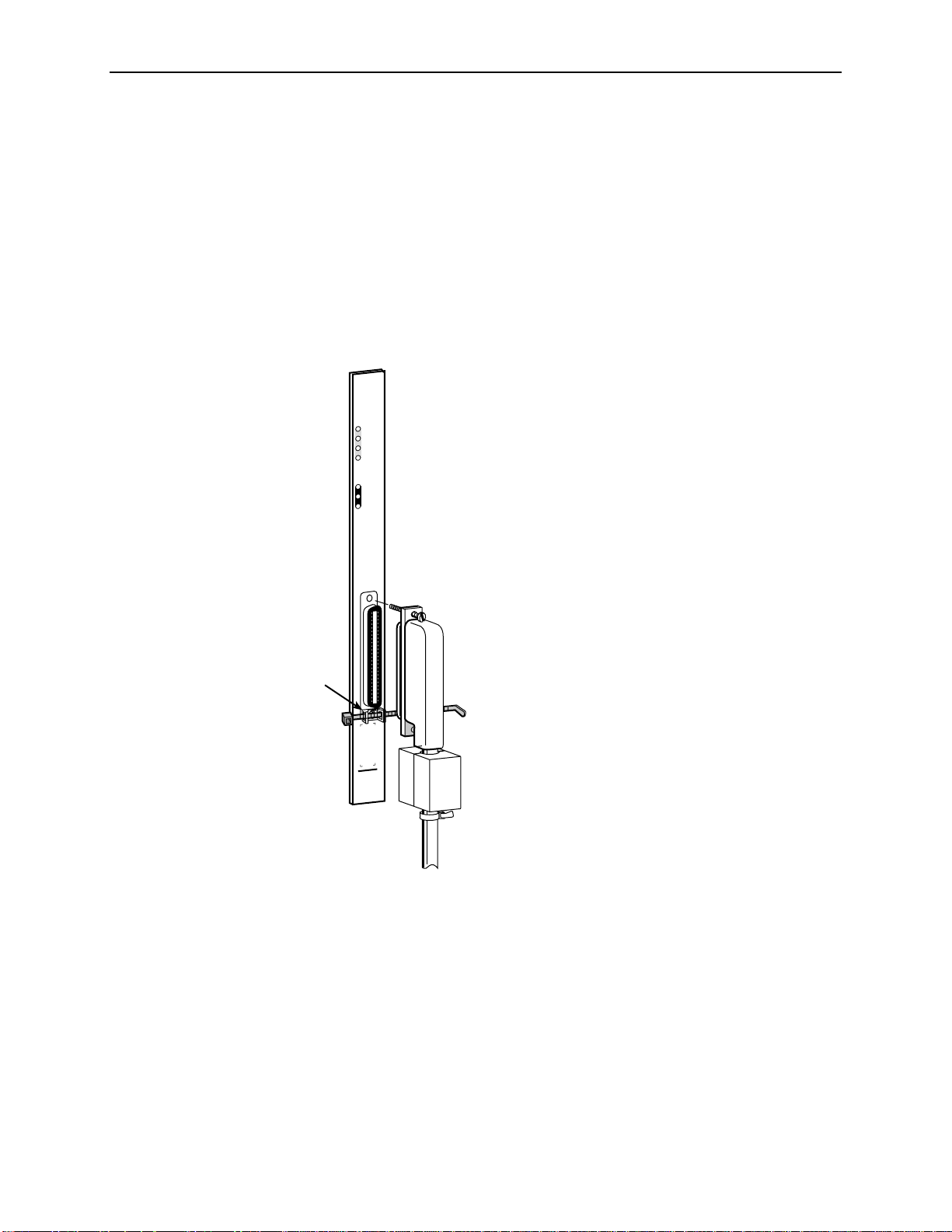
IMA Uplink Card Connector Pinouts
The IMA uplink has a RJ48M 50-pin Telco connector with 8 Tip/Ring and
8 Tip1/Ring1 connections that conforms to ANSI T1.403-1999. Paradyne offers an
octopus cable for use with the IMA uplink (Feature No. 8026-F1-001 for Models
8026 and 8028, and Feature No. 8027-F1-001 for Model 8027). These cables
contain a required ferrite to meet EMI requirements. If purchasing other Telco
cables, you must attach the supplied ferrite and cable tie as shown below. Contact
your service representative for more information.
When connecting the Telco cable, a .87-inch long panhead screw and cable tie
must be used to mount the cable to the 50-pin Telco connector as shown below.
SY
S
TE
M
OK
Alrm
Test
Uplink Alrm
E
TH
E
R
N
E
T
TX
RX
Coll
Supplied
Cable Tie
Mount
Panhead Screw
Cable Tie
A
-IM
M
C
S
1-120
E
8028
Ferrite
Cable Tie
00-16893
November 2000 8021-A2-GZ40-20
4
Page 5

Table 1 lists connector pin assignments for Models 8026 and 8028. Table 2 lists
connector pin assignments for Model 8027.
Table 1. Feature No. 8026-F1-001 Connector Pin Assignments (1 of 2)
DS1 or 120 Ohm
E1 Port
Port 1 27 5 Data Out (Tip)
Port 2 30 5 Data Out (Tip)
Port 3 33 5 Data Out (Tip)
Port 4 36 5 Data Out (Tip)
RJ48M 50-Pin Telco
Connector Pinouts
2 4 Data Out (Ring)
26 2 Data In (Tip)
1 1 Data In (Ring)
5 4 Data Out (Ring)
29 2 Data In (Tip)
4 1 Data In (Ring)
8 4 Data Out (Ring)
32 2 Data In (Tip)
7 1 Data In (Ring)
11 4 Data Out (Ring)
RJ48C Connector
Pinouts Function
35 2 Data In (Tip)
10 1 Data In (Ring)
Port 5 39 5 Data Out (Tip)
14 4 Data Out (Ring)
38 2 Data In (Tip)
13 1 Data In (Ring)
Port 6 42 5 Data Out (Tip)
17 4 Data Out (Ring)
41 2 Data In (Tip)
16 1 Data In (Ring)
Port 7 45 5 Data Out (Tip)
20 4 Data Out (Ring)
44 2 Data In (Tip)
19 1 Data In (Ring)
8021-A2-GZ40-20 November 2000
5
Page 6

Table 1. Feature No. 8026-F1-001 Connector Pin Assignments (2 of 2)
DS1 or 120 Ohm
E1 Port
Port 8 48 5 Data Out (Tip)
RJ48M 50-Pin Telco
Connector Pinouts
23 4 Data Out (Ring)
47 2 Data In (Tip)
22 1 Data In (Ring)
RJ48C Connector
Pinouts Function
Table 2. Feature No. 8027-F1-001 Connector Pin Assignments (1 of 2)
RJ48M 50-Pin Telco
75 Ohm E1 Port Function
Port 1 Data In 1 Shell (Ring)
Data Out 2 Shell (Ring)
Port 2 Data In 4 Shell (Ring)
Connector Pinouts BNC Connector
26 Pin (Tip)
27 Pin (Tip)
29 Pin (Tip)
Data Out 5 Shell (Ring)
30 Pin (Tip)
Port 3 Data In 7 Shell (Ring)
32 Pin (Tip)
Data Out 8 Shell (Ring)
33 Pin (Tip)
Port 4 Da ta In 10 Shell (Ring)
35 Pin (Tip)
Data Out 11 Shell (Ring)
36 Pin (Tip)
Port 5 Da ta In 13 Shell (Ring)
38 Pin (Tip)
Data Out 14 Shell (Ring)
39 Pin (Tip)
November 2000 8021-A2-GZ40-20
6
Page 7

Table 2. Feature No. 8027-F1-001 Connector Pin Assignments (2 of 2)
RJ48M 50-Pin Telco
75 Ohm E1 Port Function
Port 6 Da ta In 16 Shell (Ring)
Data Out 17 Shell (Ring)
Port 7 Da ta In 19 Shell (Ring)
Data Out 20 Shell (Ring)
Port 8 Da ta In 22 Shell (Ring)
Data Out 23 Shell (Ring)
Connector Pinouts BNC Connector
41 Pin (Tip)
42 Pin (Tip)
44 Pin (Tip)
45 Pin (Tip)
47 Pin (Tip)
48 Pin (Tip)
8021-A2-GZ40-20 November 2000
7
Page 8

SCM Card LEDs
The following table describes the meaning and states of the LEDs on the Hotwire
SCM card faceplate. Example faceplates are shown at left.
Type LED LED is . . . Indicating . . .
SYSTEM
OK
Alrm
Test
Uplink Alrm
ETHERNET
TX
RX
Coll
SYSTEM
OK
Alrm
Test
Uplink Alrm
ETHERNET
TX
RX
Coll
RX
SYSTEM
OK
Alrm
Test
Uplink Alrm
ETHERNET
TX
RX
Coll
SYSTEM OK Green,
Winking
Green, On
Off
Alrm Yellow, On
Off
Test Yellow, On
Off
Uplink
Alrm
Yellow, On
Off
ETHERNET TX Green,
Blinking
Off
RX Green,
Blinking
Off
Card functioning nor mally. Winking
describes a recurring pulse whe n the
LED is ON longer than OFF at a ratio
of approximately 10:1.
SCM card failure. System processing
functions have stopped.
No power to card.
Alarm is present on SCM.
No alarms.
Test in progress.
No tests.
Alarm is present on the ATM uplink.
No alarms.
Currently not used.
Currently not used.
TX
RX
SCM-DS3
10/100BT
8021
99-16634
TX
SCM-OC3
MMF
8022
99-16635
SCM-IMA
E1-75
8027
00-16891
Coll Off
Yellow,
Blinking
Currently not used.
November 2000 8021-A2-GZ40-20
8
Page 9

SCM Card Technical Specifications
Table 3. SCM Card Technical Specifications (1 of 2)
Specifications Criteria*
Size
Weight
Approvals
Safety Certifications
Power
Physical En vironment
Operating temperature
Storage temperature
Relative humidity
Shock and vibration
Physical Characteris t ics
Internal ATM Switching
Fabric
Length: 10.4 inches (26.42 cm)
Height: 11.15 inches (28.32 cm)
Width: 1.0 inches (2.54 cm)
Approximately 1.4 lbs. (0.64 kg)
Refer to the equipment’s label for approvals on product.
The SCM card contains a DC-to-DC converter that requires
48V power input. The 48V power is distributed through the
Hotwire chassis backplane.
Typical Power Dissipation = 26 watts (DS3 and E3)
or 28 watts (OC3) or 24 watts (IMA)
32° to 140° F (0° to 60° C)
–4° F to 158° F (–20° C to 70° C)
5% to 85% (noncondensing)
Withstands normal shipping and handling.
Modular Architecture from 622 Mbps to 5 Gbps,
8192 virtual circuits
DS3 Uplink Specifications
Number of ports
Connector Type
Standards Supported
Frame Formats
Line Type
Data Rates Supported
Facility Datalink Protocol
Cable Distance
* Criteria of technical specifications are subject to change without notice.
1 DS3
BNC
ANSI T1.404-94 Electrical and Jitter, ANSI T1.102-93
Electrical and Jitter
Direct or PCLP
B3ZS
44.736 Mbps
ANSI T1.107.95 Format, ANSI T1.646-95 Format, ANSI
T1.646 HEC, ITU-T I.432 Scrambler
75 ohm coaxial 900 feet
8021-A2-GZ40-20 November 2000
9
Page 10

Table 3. SCM Card Technical Specifications (2 of 2)
Specifications Criteria*
OC3 Uplink Specifications
Number of ports
Connector Type
Standards Supported
Frame Formats
Line Type
Data Rates Supported
Facility Datalink Protocol
Cable Distance
Model 8022 (MMF)
Model 8023 (SMFIR)
Model 8024 (SMFLR)
E3 Uplink Specifications
Number of ports
Connector Type
Standards Supported
Frame Formats
Line Type
Data Rates Supported
Facility Datalink Protocol
Cable Distance
1 OC3
Fiber SC connectors
ANSI T1.105.06-94 Jitter, ANSI T1.105.09 94 Jitter,
ANSI T1.117.06-91, ITU-T G.957 7/95
OC3 or STM-1 Operation, Direct Mode only
Non-Return to Zero
155.52 Mbps
ANSI T1.105 Format, ANSI T1.646 HEC, ITU-T I.432
Scrambler
2 Km (6561.7 feet)
15 Km (49,212.6 feet) SMF fiber
40 Km (131,234 feet) SMF fiber
1 E3
BNC
ETSI ETS 3000 689 Electrical and Jitter
Direct or PCLP
HDB3
34.368 Mbps
ETSI ETS 300 686 PLCP, ETSI ETS 3000 689 Direct,
ITU T1.646 HEC, ITU-T I.432 Scrambler
75 ohm coaxial 900 feet (274.3 meters)
IMA Uplink Specifications
Number of ports
Connector Type
Standards Supported
Frame Formats
Line Type
Data Rates Supported
Facility Datalink Protocol
Cable Distance
* Criteria of technical specifications are subject to change without notice.
November 2000 8021-A2-GZ40-20
10
8 T1 or E1
RJ-48M (50-pin telco)
RFC 495, ANSI T1.403, ITU G.703/G.704
T1: Superframe, extended Superframe
E1: E1, E1-CRC
T1: B8ZS
E1: HDB3
T1: 1.544 Mbps per T1 (max. 8 T1)
E1: 2.048 Mbps per E1 (max. 8 E1)
ANSI T1.403
T1/E1 (short haul): 200 meters (656 f eet) (LBO=0, –7, –15,
–22 dB)
T1/E1 (long haul): 2000 meters (6561.7 feet)
Page 11

Warranty, Sales, Service, and Training Information
Contact your local sales representative, service representative, or distributor
directly for any help needed. For additional information concerning warranty , sales,
service, repair, installation, documentation, training, distributor locations, or
Paradyne worldwide office locations, use one of the following methods:
Internet:
(Be sure to register your warranty at
Telephone:
or to speak with a company representative.
— Within the U.S.A., call 1-800-870-2221
— Outside the U.S.A., call 1-727-530-2340
Visit the Paradyne World Wide Web site at
www.paradyne.com/warranty
Call our automated system to receive current information by fax
Document Feedback
We welcome your comments and suggestions about this document. Please mail
them to Technical Publications, Paradyne Corporation, 8545 126th Ave . N., Largo ,
FL 33773, or send e-mail to
title of this document in your correspondence. Please include your name and
phone number if you are willing to provide additional clarification.
userdoc@paradyne.com
www.paradyne.com
.)
. Include the number and
.
Trademarks
Hotwire is a registered trademark of Paradyne Corporation. MVL is a trademark of
Paradyne Corporation. All other products and services mentioned herein are the
trademarks, service marks, registered trademarks, or registered service marks of
their respective owners.
Copyright © 2000 Paradyne Corporation. Printed in U.S.A.
8021-A2-GZ40-20 November 2000
11
 Loading...