

Paradyne Hotwire 7996, 7996-A2-374 User Manual

7996-A2-374
SHDSL-G.703 NTU
User’s Guide
Document Number 7996-A2-GB21-00
September 2004

7996 SHDSL NTU User’s Guide
Copyright © 2004 Paradyne Corporation.
All rights reserved.
Printed in U.S.A.
Notice
This publication is protected by federal copyright law. No part of this publication may be copied or distributed,
transmitted, transcribed, stored in a retrieval system, or translated into any human or computer language in any form
or by any means, electronic, mechanical, magnetic, manual or otherwise, or disclosed to third parties without the
express written permission of Paradyne Corporation, 8545 126th Ave. N., Largo, FL 33773.
Paradyne Corporation makes no representation or warranties with respect to the contents hereof and specifically
disclaims any implied warranties of merchantability or fitness for a particular purpose. Further, Paradyne Corporation
reserves the right to revise this publication and to make changes from time to time in the contents hereof without
obligation of Paradyne Corporation to notify any person of such revision or changes.
Changes and enhancements to the product and to the information herein will be documented and issued as a new
release to this manual.
Warranty, Sales, Service, and Training Information
Contact your local sales representative, service representative, or distributor directly for any help neede d. For
additional information concerning warranty, sales, service, repair, installation, documentation, training, distributor
locations, or Paradyne worldwide office locations, use one of the following methods:
Internet: Visit the Paradyne World Wide Web site at www.paradyne.com. (Be sure to register your warranty at
www.paradyne.com/warranty.)
Telephone: Call our automated system to receive current information by fax or to speak with a company
representative.
Within the U.S.A., call 1-800-870-2221
Outside the U.S.A., call 1-727-530-2340
Document Feedback
We welcome your comments and suggestions about this document. Please mail them to Technical Publications,
Paradyne Corporation, 8545 126th Ave. N., Largo, FL 33773, or send e-mail to userdoc@paradyne.com. Include
the number and title of this document in your correspondence. Please include your name and phone nu mber if you
are willing to provide additional clarification.
Trademarks
Acculink, Bitstorm, Comsphere, DSL the Easy Way, ETC, Etherloop, FrameSaver, GranDSLAM, GrandVIEW,
Hotwire, the Hotwire logo, Jetstream, MVL, NextEDGE, Net to Net Technologies, OpenLane, Paradyne, the
Paradyne logo, Paradyne Credit Corp., the Paradyne Credit Corp. logo, Performance Wizard, StormPort, TruePut are
registered trademarks of Paradyne Corporation. ADSL/R, Connect to Success, Hotwire Connected, iMarc, JetFusion,
JetVision, MicroBurst, PacketSurfer, Quick Channel, ReachDSL, Reverse Gateway, Spectrum Manager, and
StormTracker are trademarks of Paradyne Corporation. All other products and services mentioned herein are the
trademarks, service marks, registered trademarks, or registered service marks of their respective owners.
CE Marking
When the product is marked with the CE mark on the equipment label, a supporting Declaration of Conformity may be
downloaded from the Paradyne World Wide Web site at www.paradyne.com. Select Library → Technical Manuals
→ CE Declarations of Conformity.
2 September 2004 7996-A2-GB21-00

7996 SHDSL NTU User’s Guide
Table of Contents
CHAPTER 1 INTRODUCTION...........................................................................................................................5
1.1 OVERVIEW .......................................................................................................................................................5
1.2 FEATURES.........................................................................................................................................................5
1.3 APPLICATIONS ..................................................................................................................................................6
1.4 FRONT PANEL LED INDICATORS ......................................................................................................................7
CHAPTER 2 HARDWARE INSTALLATION....................................................................................................8
2.1 REAR PANEL CONNECTORS ..............................................................................................................................8
2.2 INSTALLATION..................................................................................................................................................9
CHAPTER 3 MANAGEMENT ..........................................................................................................................10
3.1 CONSOLE MANAGEMENT ...............................................................................................................................10
3.2 TELNET MANAGEMENT..................................................................................................................................12
3.3 SNMP MANAGEMENT ...................................................................................................................................12
CHAPTER 4 SYSTEM SETUP ..........................................................................................................................13
4.1 LOGIN ............................................................................................................................................................13
4.2 MAIN MENU...................................................................................................................................................14
4.3 CONFIGURATION ............................................................................................................................................15
4.4 LOGOUT .........................................................................................................................................................22
CHAPTER 5 OPERATION MODE ...................................................................................................................23
5.1 SELECTING DEVICE ........................................................................................................................................24
5.2 SELECTING MODE ..........................................................................................................................................25
CHAPTER 6 MAINTENANCE..........................................................................................................................26
6.1 PERFORMANCE...............................................................................................................................................26
6.2 ALARM MONITORING.....................................................................................................................................33
6.3 LOOPBACK TEST ............................................................................................................................................34
6.4 SYSTEM MAINTENANCE.................................................................................................................................38
6.5 SYSTEM RESET AND SOFTWARE DOWNLOAD .................................................................................................41
CHAPTER 7 TROUBLESHOOTING ...............................................................................................................44
APPENDIX A SPECIFICATIONS.........................................................................................................................45
APPENDIX B PIN ASSIGNMENTS .....................................................................................................................46
List of Figures
Figure 1-1 Applications of 7996-A2-374 ........................................................6
Figure 1-2 7996-A2-374 Front View..............................................................7
Figure 2-1 7996-A2-374 Rear Panel Connectors-DC power ............................... 8
Figure 2-2 7996-A2-374 Rear Panel Connectors-AC power ............................... 8
Figure 3-1 Main Menu............................................................................... 10
Figure 4-1 Main Menu............................................................................... 13
Figure 4-2 Configuration Menu ................................................................... 15
7996-A2-GB21-00 September 2004 3

7996 SHDSL NTU User’s Guide
Figure 4-3 System Configuration Screen...................................................... 16
Figure 4-4 Local Management Port Configuration Screen................................ 16
Figure 4-5 System Date and Time Setting Screen ......................................... 17
Figure 4-6 Password Configuration Screen ................................................... 18
Figure 4-7 SNMP Configuration Screen ........................................................ 19
Figure 4-8 SHDSL Interface Configuration Screen ......................................... 20
Figure 4-9 E1 Interface Configuration Screen I ............................................. 21
Figure 5-1 Operation Mode Indication ......................................................... 23
Figure 5-2 Select Device Menu................................................................... 24
Figure 5-3 Remote Device Configuration Main Menu ...................................... 24
Figure 5-4 Select NE Mode Menu ................................................................ 25
Figure 6-1 Performance Data Menu............................................................. 26
Figure 6-2 SHDSL Performance Data Menu .................................................. 26
Figure 6-3 Current Quarter Performance Screen for SHDSL............................ 27
Figure 6-4 Previous 96 Quarters Performance Screen for SHDSL ..................... 27
Figure 6-5 Current & Previous 7 Days Performance Screen for SHDSL.............. 28
Figure 6-6 Clear Performance Data Screen for SHDSL ................................... 28
Figure 6-7 Current Quarter Performance Screen for E1.................................. 29
Figure 6-8 Previous 96 Quarters Performance Screen for E1........................... 30
Figure 6-9 Current & Previous 7 Days Performance Screen for E1.................... 30
Figure 6-10 Clear Performance Data Screen for E1........................................ 31
Figure 6-11 Threshold Set Menu................................................................. 31
Figure 6-12 SHDSL Threshold Setup Screen................................................. 31
Figure 6-13 E1 Threshold Setup Screen....................................................... 32
Figure 6-14 Current Alarm Status Screen .................................................... 33
Figure 6-15 Alarm History Screen............................................................... 33
Figure 6-16 Test and Loopback Menu .......................................................... 34
Figure 6-17 SHDSL Loopback Screen .......................................................... 34
Figure 6-18 SHDSL BER Test Screen ........................................................... 35
Figure 6-19 E1 Loopback Screen ................................................................ 36
Figure 6-20 E1 BER Test Screen ................................................................. 37
Figure 6-21 Configuration Database Maintenance Menu ................................. 38
Figure 6-22 Reset & Software Download Menu ............................................. 41
4 September 2004 7996-A2-GB21-00

7996 SHDSL NTU User’s Guide
Chapter 1 Introduction
1.1 Overview
This user’s manual provides general information about the features, functions and operation of
the 7996-A2-374 SHDSL NTU.
The 7996-A2-374 is a Network Termination Unit (NTU) that utilizes SHDSL technology,
combining the best of 2B1Q SDSL and HDSL2 to achieve fast and efficient data transmission in
both directions, over a single copper telephone line.
The 7996-A2-374 has an industry standard E1 interface. Based on TC-PAM coding, the
7996-A2-374 supports data rates of up to 2,048 kbps. It is suitable for leased line applications
such as video conferencing, Internet access, and Digital Data Network (DDN) access.
Featuring remote control capability, the local 7996-A2-374 is able to perform configuration,
performance monitoring, querying, diagnostics, and all maintenance functions over the remote
NTU via the DSL line.
1.2 Features
TDM-based SHDSL NTUs guarantee real bandwidth without the large overhead required
by ATM-based NTUs
Full remote control capability via SHDSL Embedded Operation Channel
Complies with ITU-T G.991.2 (G.shdsl)
E1 DTE interface
Versatile loopbacks for diagnostics
Built-in test pattern generator and detector
SHDSL and E1 line performance monitoring (PM)
96-quarter-hour / 7-day PM storage
Local control via RS-232 management port (VT100) and LAN port (Telnet access)
SNMP management through Ethernet LAN port
Software download capability
7996-A2-GB21-00 September 2004 5
7996 SHDSL NTU User’s Guide
1.3 Applications
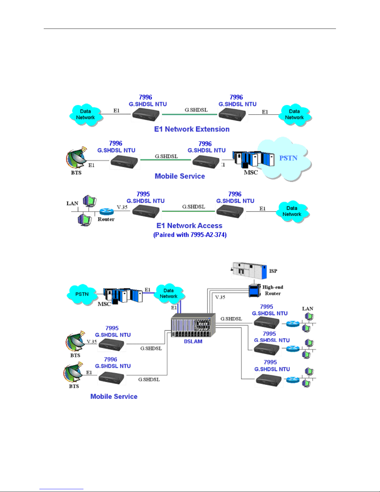
Figure 1-1 shows the applications of the 7996-A2-374 SHDSL NTU.
Figure 1-1 Applications of 7996-A2-374
6 September 2004 7996-A2-GB21-00
7996 SHDSL NTU User’s Guide
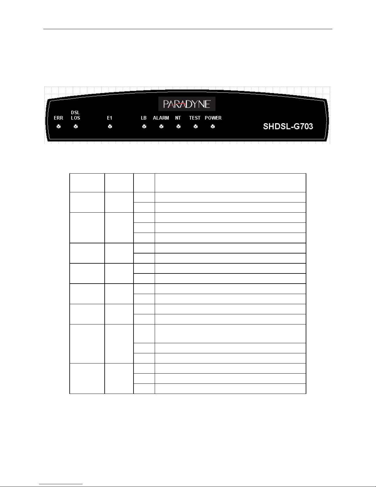
1.4 Front Panel LED Indicators
The 7996-A2-374 has eight LED indicators. These LEDs indicate power status, diagnostics,
machine status, data activity, and alarm conditions.
Figure 1-2 7996-A2-374 Front View
LED
Indicator
POWER Green
Color Mode Function
On Power is supplied
Off No power is connected
On Bit Error testing
TEST Green
Blink Self testing
Off Normal operation
NT Green
On NT mode enabled
Off LT mode enabled
ALARM Red
On Major alarm detected
Off No major alarm detected
LB Yellow
On Loopback testing
Off Normal operation
E1 Green
On E1 connection is working
Off E1 connection is not working
On
DSL LOS Red
Blink DSL link is training
Off DSL link is connected
On Self-test error
ERR Yellow
Blink Bit error test error
Off Normal operation
Loss of signal (DSL link is out of service or not
connected)
Note: The average training period for the SHDSL line is one minute and forty seconds. If the training
period exceeds three minutes, or it fails (the DSL LOS LED keeps blinking), it means the line
quality is poor or the link distance is too long for the SHDSL NTU to train. Contact your service
provider.
7996-A2-GB21-00 September 2004 7
Table 1-1 7996-A2-374 LEDs
7996 SHDSL NTU User’s Guide
Chapter 2 Hardware Installation
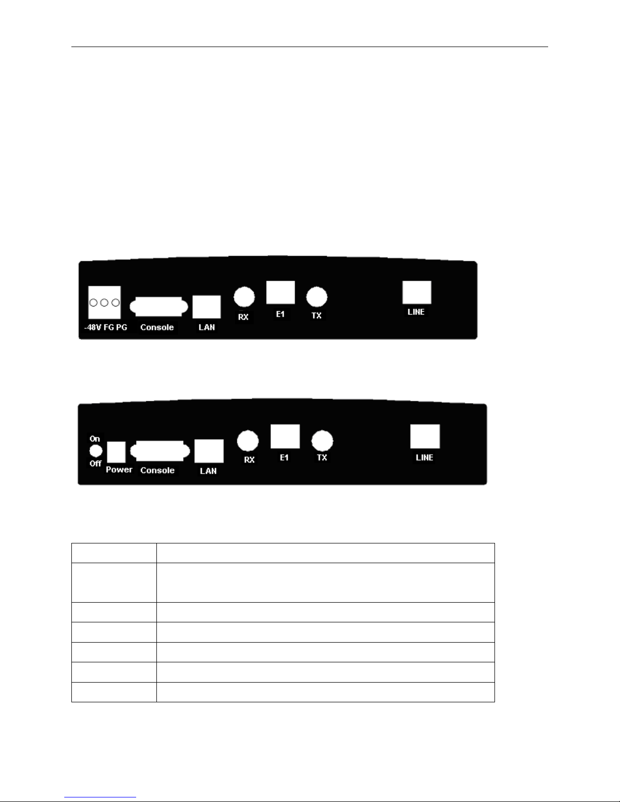
2.1 Rear Panel Connectors
There are two types of rear panels for the 7996-A2-374. Their only difference is the power
supply: –48 VDC or 110/220 VAC.
Figure 2-1 7996-A2-374 Rear Panel Connectors – DC power
Figure 2-2 7996-A2-374 Rear Panel Connectors – AC power
Interface Description
–48V FG PG
Power
The –48 VDC version has three pins: –48V, FG, PG (Fig.2-1).
The AC version has a power jack and a power switch (Fig.2-2).
Console DB9 female connector for connection to a PC COM port
LAN RJ45 connector for SNMP network management
E1 RJ45 connector for a 120 ohm, balanced E1 interface
TX and RX BNC connector for a 75 ohm, unbalanced E1 interface
LINE RJ45 connector for the SHDSL connection
8 September 2004 7996-A2-GB21-00
Table 2-1 7996-A2-374 Rear Connectors
7996 SHDSL NTU User’s Guide
2.2 Installation
Follow the step-by-step instructions below for the hardware installation:
Connect the LINE port to your DSL line. Step 1
Step 2
Step 3
Step 4
Step 5
Connect the LAN port to the SNMP management network with an RJ45 connector cable.
Connect the E1 interface to the Data network.
Connect the Console port to the VT100 compatible terminal or PC COM port with an
RS232 cable.
Connect the Power to the power input.
For the DC version, connect the power pins as follows:
–48V: Connect to –48VDC power supply source.
PG: Connect to the ground of –48VDC power supply source.
FG : Connect to the frame ground.
For the AC version, connect the Power jack to the power cable of the 110 or 220 VAC power
adapter.
Step 6
After power on (for the AC version, turn the power switch to the ON position), the
7996-A2-374 performs a self-test. During the self-test, all LEDs will keep flashing back
and forth sequentially. The test items include system RAM, flash memory and application
software. If an error is found in RAM, the ALARM LED will be ON. If an error is found
in flash memory or application software, the ALARM LED will keep flashing.
Caution: If the SHDSL NTU fails to power on, or it malfunctions, first verify that the
power supply is correctly connected, and then power it on again.
7996-A2-GB21-00 September 2004 9
7996 SHDSL NTU User’s Guide
Chapter 3 Management
This chapter describes the three ways to manage the SHDSL NTU: Console, Telnet and SNMP.
Chapters 4 to 6 cover the configuration and maintenance of the SHDSL NTU in a console or
Telnet session.
3.1 Console Management
Configure the following parameters for your VT100 terminal emulation program:
Baud rate: 38,400 bps
Parity: None
Data bits: 8
Stop bit: 1
Flow control: None
After the session parameters are set up, start the VT100 emulator program on the PC. The Press
Any Key to Login… message will be shown in the middle of the screen. Press any key. When
the login prompt appears, type the password and press the Enter key to display the main menu as
shown below. For initial login, no password is required.
10 September 2004 7996-A2-GB21-00
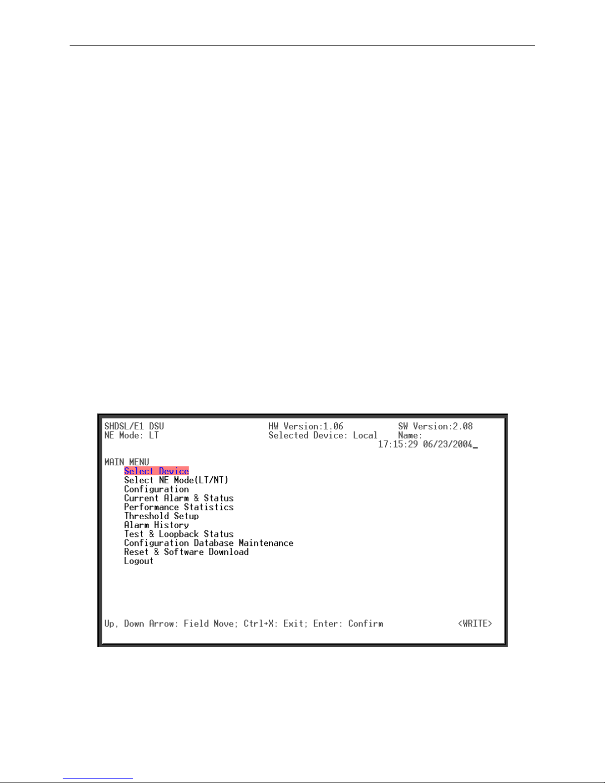
Figure 3-1 Main Menu

7996 SHDSL NTU User’s Guide
Press the Up and Down arrow keys to select fields, and press the Left and Right arrow keys to
select the parameters of fields. Type <Ctrl-X > to exit and <Enter > for confirmation.
The main menu includes the following fields:
Select Device (Local/Remote): Select the SHDSL NTU to be configured. (Only appears in
LT mode.)
Select NE Mode (LT/NT): Select NT or LT operation mode.
Configuration: Configure system parameters.
Current Alarm & Status: Show the status of current alarms.
Performance Statistics: Show the statistics of performance monitoring.
Threshold Setup: Set the day and quarter threshold.
Alarm History: View all of the alarm records.
Test & Loopback Status: Perform a loopback, BER and self-test.
Configuration Database Maintenance: Upload, download, save the configuration
database, and set the configuration database to the factory defaults.
Reset & Software Download: Perform a system reset or software download.
Logout: Exit the system.
7996-A2-GB21-00 September 2004 11
7996 SHDSL NTU User’s Guide
3.2 Telnet Management
The configurations in a Telnet session are the same as in console. To access the SHDSL NTU via
Telnet, follow the steps below:
STEP 1: Connect the SHDSL NTU’s LAN port to the Network Interface Card (NIC) in a PC
using a crossover cable, or to an Ethernet hub using a straight-through cable.
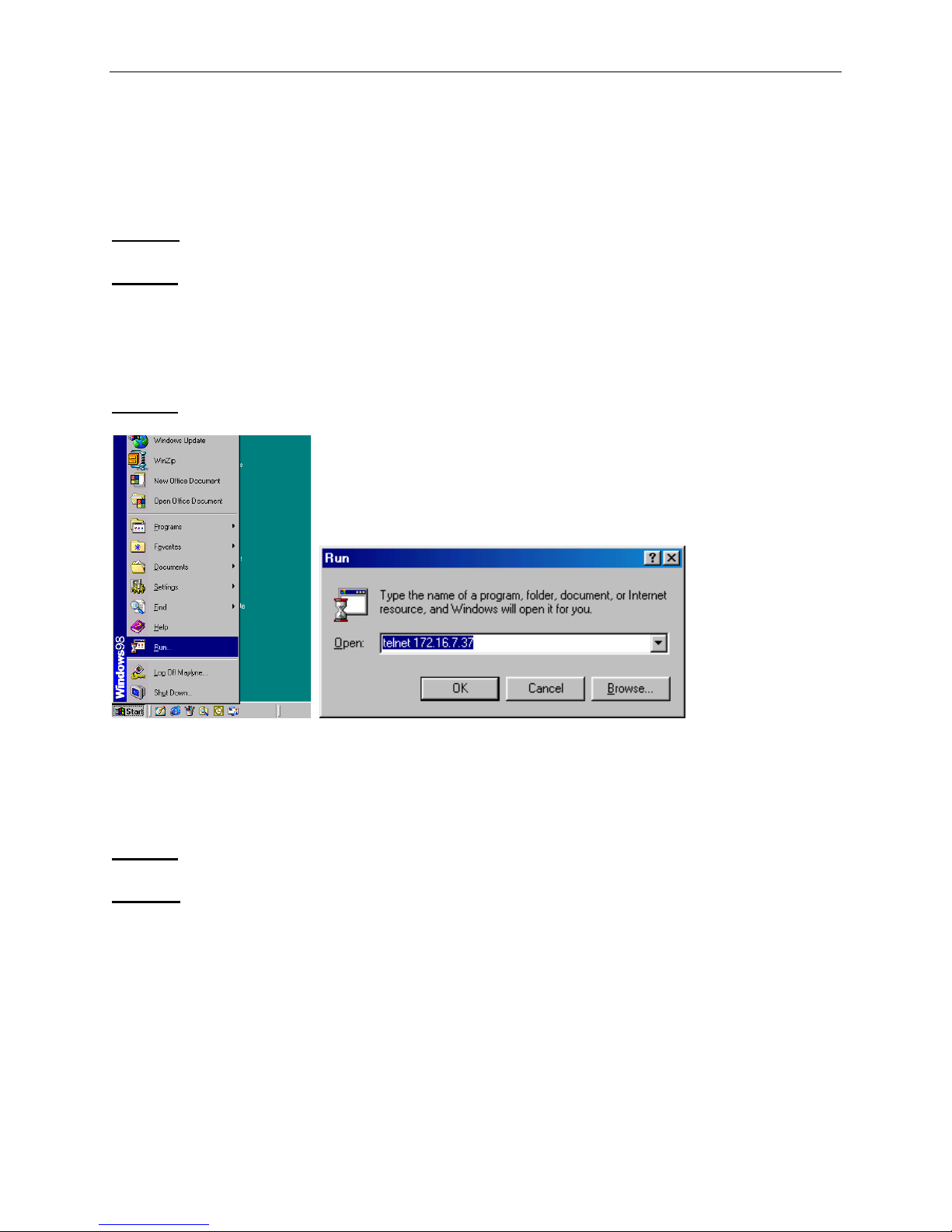
STEP 2:
STEP 3:
In Windows, click on Start and choose Run. Type:
telnet xxx.xxx.xxx.xxx.
where xxx.xxx.xxx.xxx is the IP address of your SHDSL NTU. The default NTU IP
address is 172.16.7.37.
Refer to Chapters 4 to 6 to configure and maintain the SHDSL NTU.
3.3 SNMP Management
To manage the NTU using SNMP, follow the steps below:
STEP 1:
STEP 2:
12 September 2004 7996-A2-GB21-00
Connect the SHDSL NTU’s LAN port to the Network Interface Card (NIC) in your PC
with a cross-over cable, or an Ethernet hub with a straight-through cable.
Run your SNMP MIB browser to configure the SHDSL NTU. The default NTU IP
address is 172.16.7.37.
7996 SHDSL NTU User’s Guide
Chapter 4 System Setup
4.1 Login
Configure the following parameters for your VT100 terminal emulation program.
Console session parameters (factory default)
Baud rate: 38400 bps
Parity: None
Data bits: 8
Stop bit: 1
Flow control: None
Run the VT100 emulator program. In a while, the Press Any Key to Login… message appears.
Press any key. When a login prompt appears, type a password and then press the Enter key to
display the main menu as shown below. No password is required the first time you log in.
7996-A2-GB21-00 September 2004 13
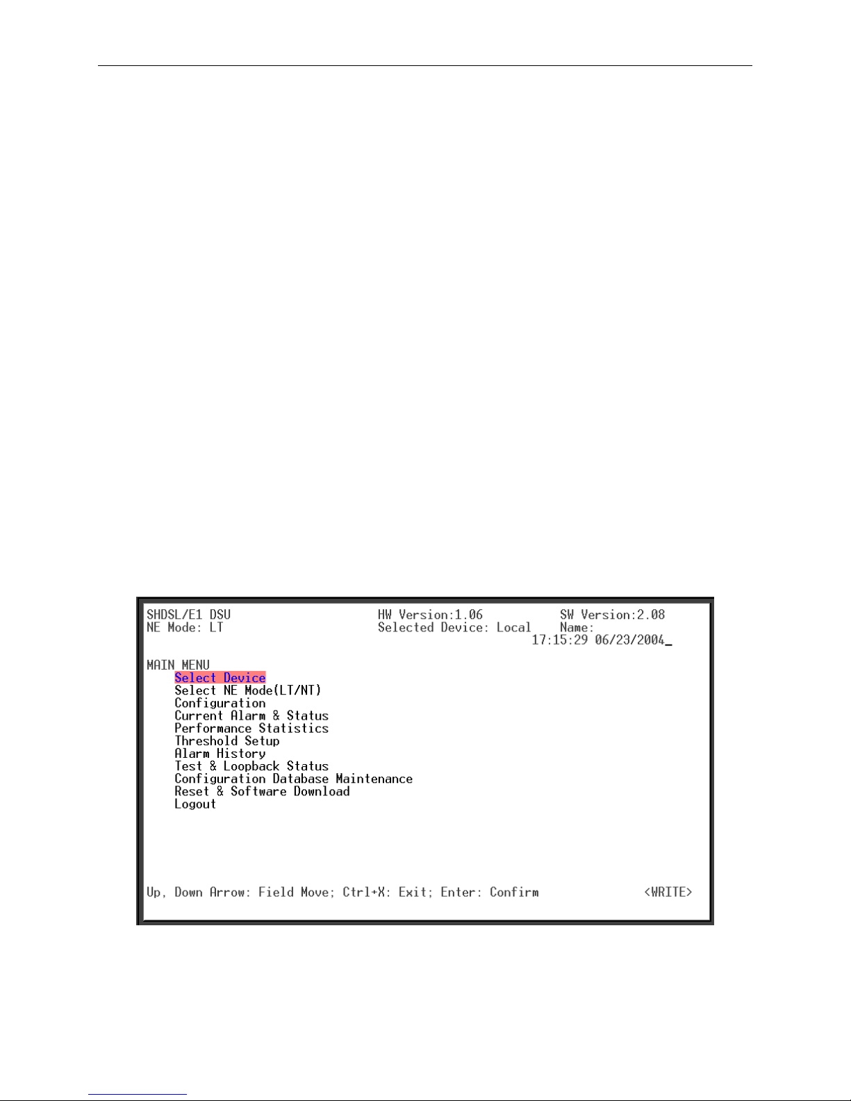
Figure 4-1 Main Menu

7996 SHDSL NTU User’s Guide
4.2 Main Menu
Press the Up and Down arrow keys to select fields, and press the Left and Right arrow keys to
select the parameters of fields. Type <Ctrl-X > to exit and <Enter > for confirmation.
The main menu includes the following fields:
Select Device: Select the device to be configured. This field is only available in LT
mode.
Select NE Mode (LT/NT): Select NT or LT operation mode. The factory default is LT
mode.
Configuration: Configure system parameters.
Current Alarm & Status: Show the status of current alarms.
Performance Statistics: Show the statistics of performance monitoring.
Threshold Setup: Set the thresholds for system performance monitoring.
Alarm History: View and clear alarm records.
Test & Loopback Status: Perform a loopback, BER and self-test
Configuration Database Maintenance: Upload; download; save the configuration
database; and set the configuration database to factory default.
Reset & Software Download: Perform a system reset or software download
Logout: Exit the system
14 September 2004 7996-A2-GB21-00
 Loading...