

Paradyne 7974, 7975, 7976, Hotwire 7974-A2, Hotwire 7975-A2 Installation Instructions Manual
...
Hotwire® TDM SDSL Standalone Termination Units
Models 7974-A2, 7975-A2, and 7976-A2
Installat i on Inst r uct ions
Document Number 7900-A2-GN11-20
December 2001
Product Documentation Online
Complete documentation for this product is availab le at
Library → Technical Manuals → Hotwire DSL Systems.
Select the following doc um ent:
7900-A2-GB21
Hotwire TDM SDSL Standalone Termination Units,
Models 7974-A2, 7975-A2, 7976-A2, User’s Guide
To order a paper copy of a Paradyne document:
Within the U.S.A., call 1-800-PARADYNE (1-800-727-2396)
Outside th e U.S.A., call 1-727-530-8623
Be sure to register your warranty at
www.paradyne.com/warranty
Pack ag e C hec kli st
Verify that your package contains:
❑
Hotwire® TDM SDSL Standalone Termination Unit
❑
24 VDC power transformer with separate power cable
– or –
6-conductor direct connection DC power cable
www.paradyne.com
.
. Select
❑
8-position-modular-to-8-position-modular network cable
❑
DB9-to-8-position modular terminal cable
Notify your sales representative if anything is missi ng.
1

Installation Overview
Installation and configur ation of the Hotwire 797 x Standalone Termination Unit consists
of:
Connecting power to the unit.
Connecting to the network.
Connecting to a DTE.
Connecting a system terminal.
Provid ing initial unit id entity information or changing e xisting identity information.
Configuring your unit using the Configuration Edit menus.
Before you install the uni t, read the
See the User’s Guide for additional inf ormati on about:
Configuration Options
Messages and Troubleshooting
Technical Specif ications
Connectors , Cables, and Pin Assignments
Important Safety Instructions
on page 35.
Connecting Power to the Unit
If your package includes a power transformer:
1. Plug the power cable into an AC outlet havi ng a nom inal voltage rating between
100–240 VAC.
2. Connect the power cable to the transformer.
3. Connect the output cable of the tr ansformer to the connector marked PO WER on
the rear panel.
If your package includes a direct-connecti on DC pow er cable:
Connect t he unit to an external +24 o r –48 VDC SEL V (Saf ety Ext ra Low Voltage) power
source as described in the following section.
2
Connecting the Unit to an Optional Exter nal +24 or –48 VDC Power
99-16291
23
546
1
Source
Using the DC power cable, the unit is capable of operating on a +24 VDC or –48 VDC
SELV power supply.
Procedure
To use the DC power cable for +24 VDC:
1. Connect the green wire to a suitable ground.
2. Connect the orange wire to the +24 VDC source.
3. Connect the white wi re t o the re turn.
4. Cut the black, red, and blue wires off at the outer insulation.
5. Plug the power connector into the unit.
Procedure
To use the DC power cable for –48 VDC:
1. Connect the green wire to a suitable ground.
2. Connect the orange wire to the –48 VDC source.
3. Connect the b lack wire to the return.
4. Cut the red, white, and bl ue wires off at the outer insulation.
5. Plug the power connector into the unit.
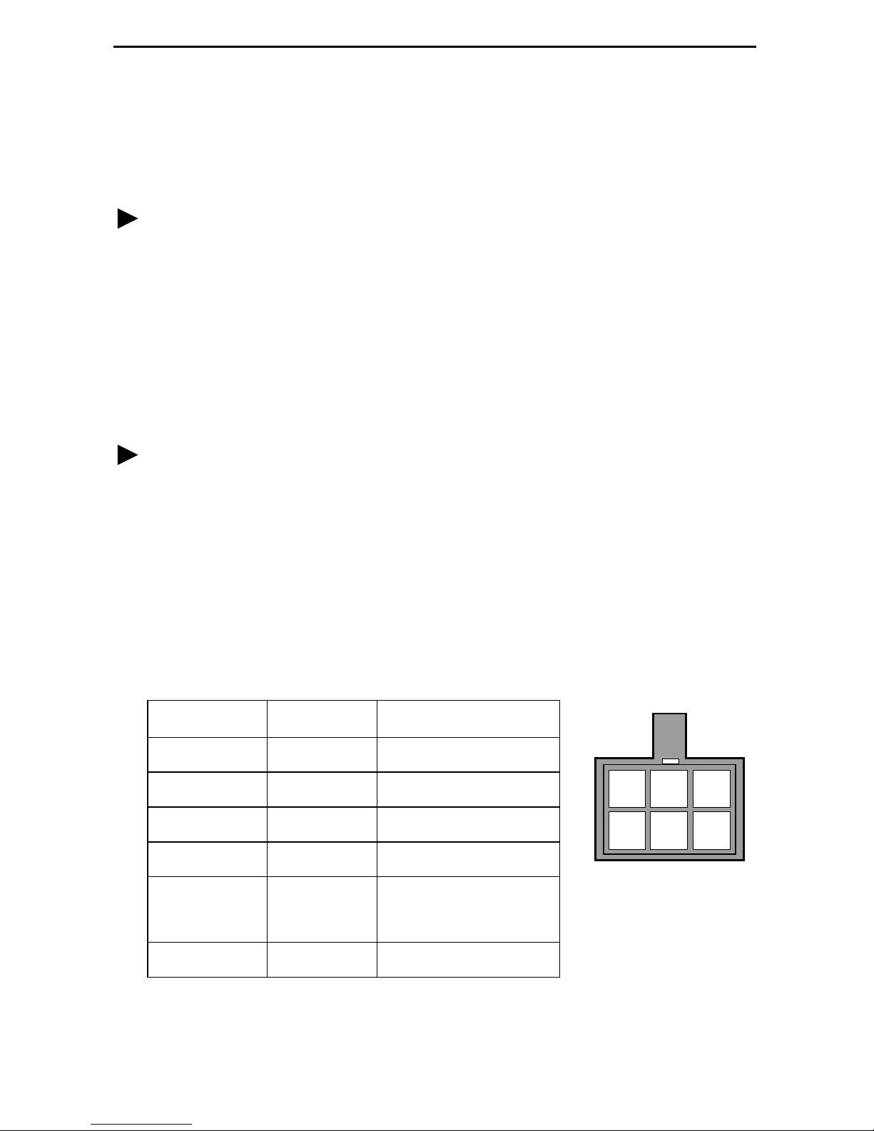
Power Cable Pinouts
Pin Number Wire Color Signal
1Black–48 VDC Return
2Red–48 VDC Return
3 Green Ground
4 White +24 VDC Return
5 Orange –48 VDC
+24 VDC
6 Blue No Connection
3
Connecting to the Network
Procedure
To connect your unit to the network:
1.
Connect one end of the supplied 8-position-modular-to- 8-position-modular network
cable into the rear panel DSL jack .
2.
Connect the other end to your DSL network interface.
NOTE:
not
Do
performance of the unit. Use only Cat 5 twisted-pair network cab le.
use a flat VF network cable as this may severely degrade the
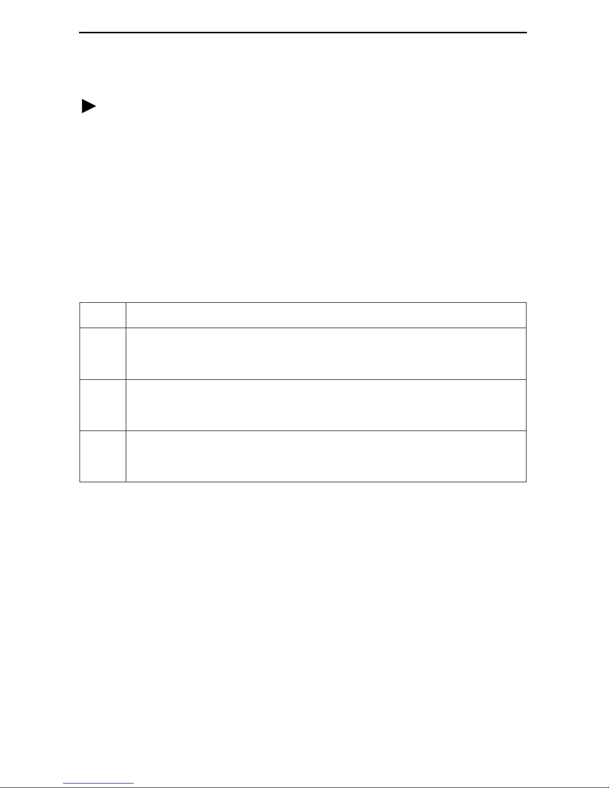
Connecting to a DTE
Model DTE Connection
7974 The DSX-1 interface is an RJ48C, 8-position, unkeyed modul ar connector.
An RJ48C-to-DB15 T1 network inter face adapter cable is availab le from
Paradyne.
7975 The synchrono us int erf ac e is a 25-pi n EIA-5 30-A interface. Depending on the
cable used, the interface can be adapted to an X.21, RS-449, or V.35
interface.
7976 The G.703 interf ac e is either two BNC conne ctors (Transmit and Recei ve ) fo r
a 75-ohm unbalanced interface or an RJ48C, 8-position, unkeyed modular
connector f or a 120-ohm balanced i nterface .
Connectors, Cables, and Pin Assignments
See
the connectors and cables.
in the User’s Guide for specificat ions of
4
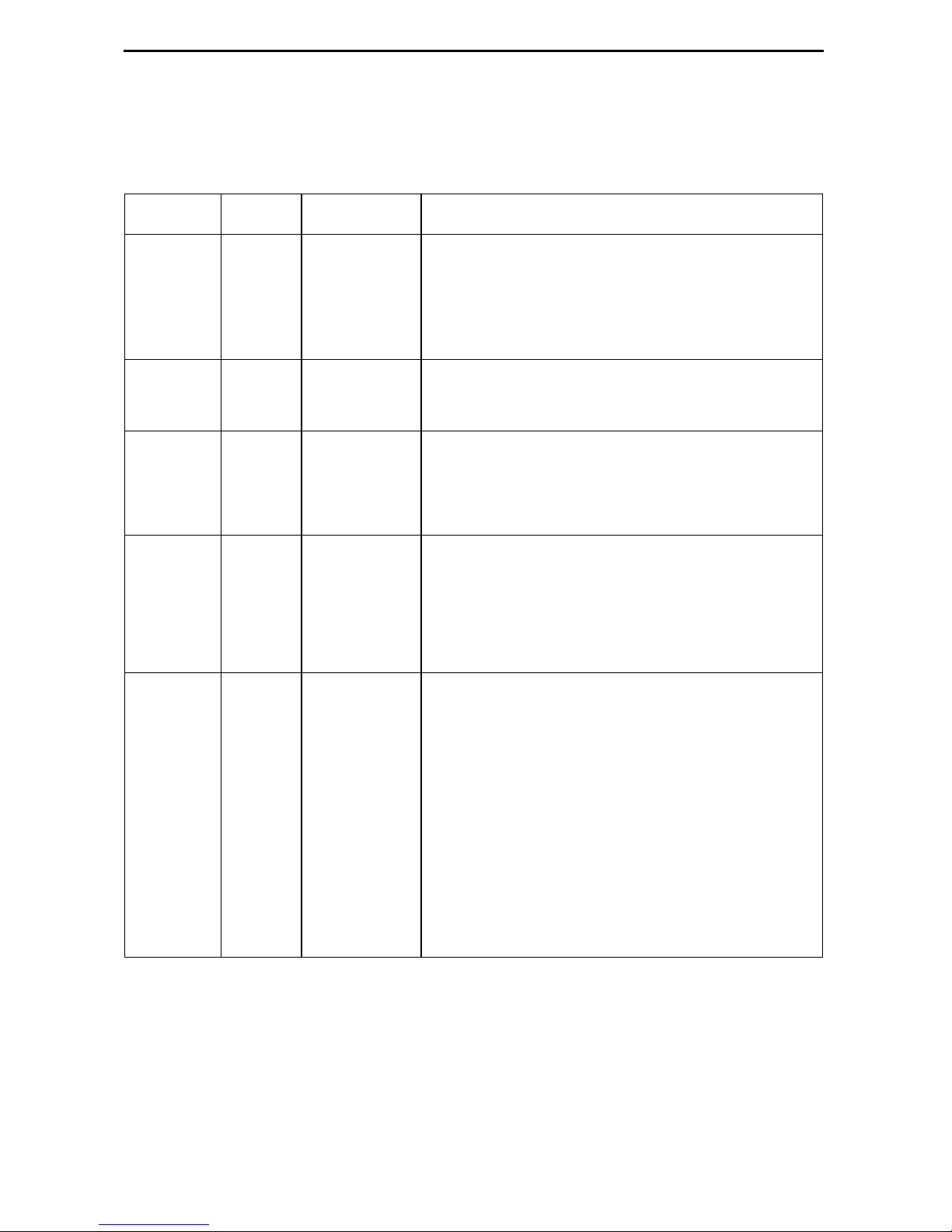
LEDs
The fol lowing table contains a description of the LEDs on the Hotwire 797x Standalone
Termination Unit’s front panel .
Label Color LED is . . .*
POWER Green On
Off
Slow Cyclin g
ALARM Red O n
Off
TEST Yellow On
Off
Slow Cyclin g
DSL Green On
Off
Slow Cyclin g
Fast C ycling
Indicating . . .
Normal operation.
No power to the unit.
Unit is in minimum mode and a download is
required.
Device failure, or self-test has failed.
Self-test pass ed.
Loopback test or 511 test pattern in progress.
No tests in progress.
Self-test in progress.
DSL link is up.
The DSL link is down.
DSL training in progress.
An OOF condition.
DSX-1
DTE
G.703
* Slow Cycling: LED tu rns off and on in equal duration once per second.
Fast Cycling: LED turns off and on in equal duration 5 times per second.
Pulsing: LED turns off momentari ly once per second.
Green On
Off
Slow Cyclin g
Fast C ycling
DTE port is operational.
DSX-1: No signal on DTE port.
Sync DTE: Conf igur ed contr ol l eads (DTR/R TS)
are not asserted.
G.703: No signal on DTE port.
DSX-1: Yellow Alarm Indication received.
Sync DTE: Not applicable.
G.703: Remote Alarm Indication receiv ed.
DSX-1: OOF, LOF, EER, or AIS condition.
Sync DTE: Not applicable.
G.703: OOF, LOF, EER, or AIS condition.
5
Connecting to a System Terminal
An optional system maintenance terminal may be attached to your Hotwire 797x
Standalon e Termination Unit through the modular jack on the rear panel . The system
maintenance terminal allows you to vi ew the status of the unit and chan ge configuration
options . The terminal must be a VT100-compatible terminal or a PC running terminal
emulati on software.
Procedure
To connect your unit to a system terminal:
1. Connect the 9-pin end of the supplied terminal cab le into a COM port on your PC.
2. Plug the other end in to the modular jack on the rear panel.
3. Set the communication parameters on your PC or terminal to:
— 9600 baud
— 8 bit char acters
— no parity
— 1 stop bit
— no flow control
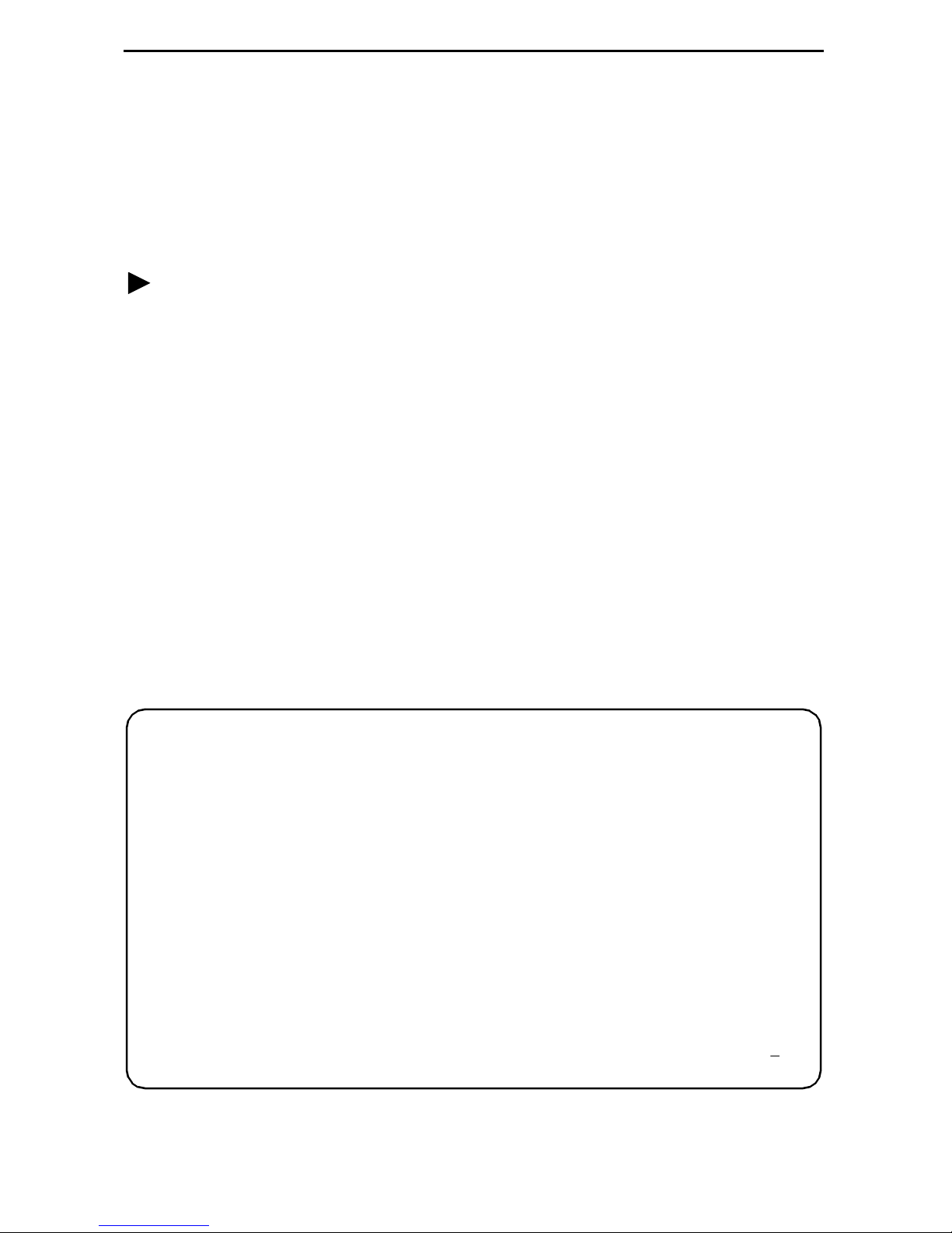
Press E n te r fr o m your te r m inal or P C to act iva te th e Ma in M en u for the at ta c h ed un i t.
The system runs di agnost ics and st atu s check s. Aft er a f e w moment s, th e Main Men u or
Logon screen appears on your terminal .
main Hotwire
Model 797x
MAIN MENU
Status
Test
Configuration
Control
----------------------------------------------------------------------------Ctrl-a to access these functions E
xit
6
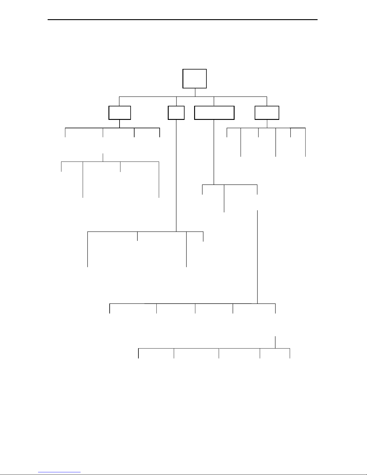
Asynchronous Terminal Interface Menu
The following illustration shows the menu paths to the different terminal screens.
Main
Status Test
System and
Test Status
Network
Error
Statistics
Performance
Display
Statistics
7974: DSX-1 Statistics
7975: (Not Applicable)
7976: G.703 Statistics
Network
Performance
Statistics
7974: (Not Applicable)
7975: Sync Data Port Tests
7976: (Not Applicable)
7974: Network and DSX-1 Tests
7975: Network Tests
7976: Network and G.703 Tests
LEDs
Performance
Identity
Current
Network
Factory
Device
Tests
Configuration Control
Change
Identity
Administer
Download
Logins
Code
Apply
Download
Current Configuration
Config
Edit/Display
Configuration
Loader
Abort
All
Tests
Reset
AutoRate
Reset
Device
Network
7974: DSX-1
7975: Sync Port
7976: G.703
Telnet
Communication
Session
Protocol
7
System
Options
General SNMP
Management
Communication
Port
SNMP NMS
Security
Management
and
Communication
SNMP
Traps
01-16496-03

Entering Identity Information
After acce ssing your unit f or the first time, use the Change Identit y screen to determine
SNMP administrative system informati on that will be displ ayed on the Identity screen of
the Status branch. To access the Identi ty screen, f oll ow this menu selection sequence:
Main Menu → Control → Change Identity
Selecting a C onfigur ation Method
You can make configuration changes either throu gh a VT100-compatibl e terminal and
the unit’s Configuration menus or by manually changing switches on the board. The unit
is shipped with the switchpacks disabled to allow settings to be made through the
Configuration menus. See the User’s Guide fo r detailed inf ormation about the
configu ration options and switch setti ngs.
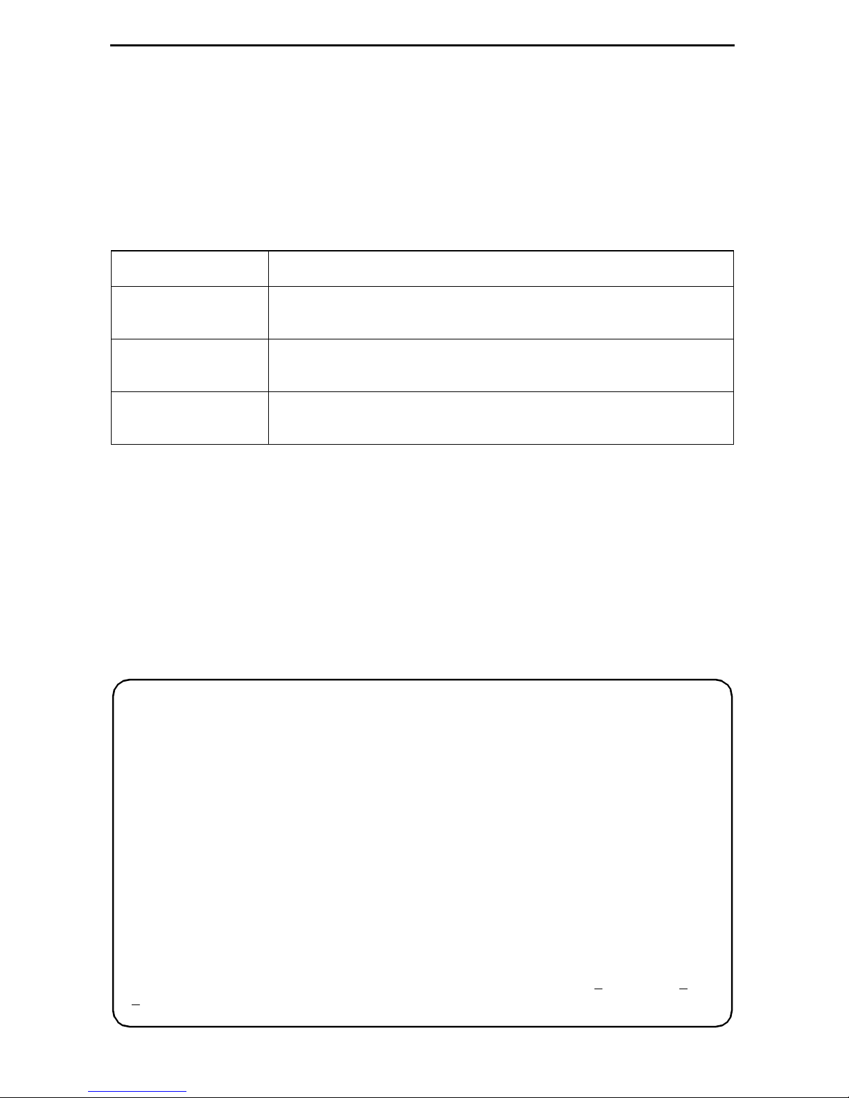
Configuring the U nit Using the Configuration Menus
Use the Configuration menu to select, display, or change configuration option settings.
NOTE:
The Hotwir e 797x Standalone Termination Un it is shipped configured as an NTU. If
using this unit as an NTU, the confi guration options may not need to be altered.
The unit has two sets of configuration option settings:
The Current Configuration: The unit’s active set of configurat ion options.
The Defaul t Factory Configuration: A read- only configu ration area containing the
factory default configuration options.
8
Displaying Configuration Opti ons
To display configuration options, you must fi rst load a configuration into the edit area. To
load a conf igur ation o ption s et int o the conf igur atio n edit ar ea, follow this menu sel ecti on
sequence:
Main Menu → Configuration (Load Configuration F rom)
Make a selection by placing the cursor at your choice and pressing Enter.
If you select . . . Then . . .
Current
Configuration
Default Factory
Configuration
Configuration
Loader
The selected configuration opti on set is loaded and the
Configurati on Edit/Display menu screen appear s.
The selected configuration opti on set is loaded and the
Configurati on Edit/Display menu screen appear s.
The Configurati on Loader screen is displayed al lowing you to
upload or download configurations from a TFTP server.
Configuration Edit/Display
The Configuration Edit/Dis play screen is displayed when the current or default
configuration is loaded. To access the Configuration Edit/Display screen, follow this
menu selection sequence:
Main Menu → Configuration → Current Configuration
– or –
Main Menu → Configuration → Default Factory Configuration
main/config/edit
Model: 797x
CONFIGURATION EDIT/DISPLAY
Network
DSX-1 | SYNC Port | G.703
System Options
Communication Port
Management and Communication
----------------------------------------------------------------------------Ctrl-a to access these functions, ESC for previous menu MainMenu Exit
ave
S
9
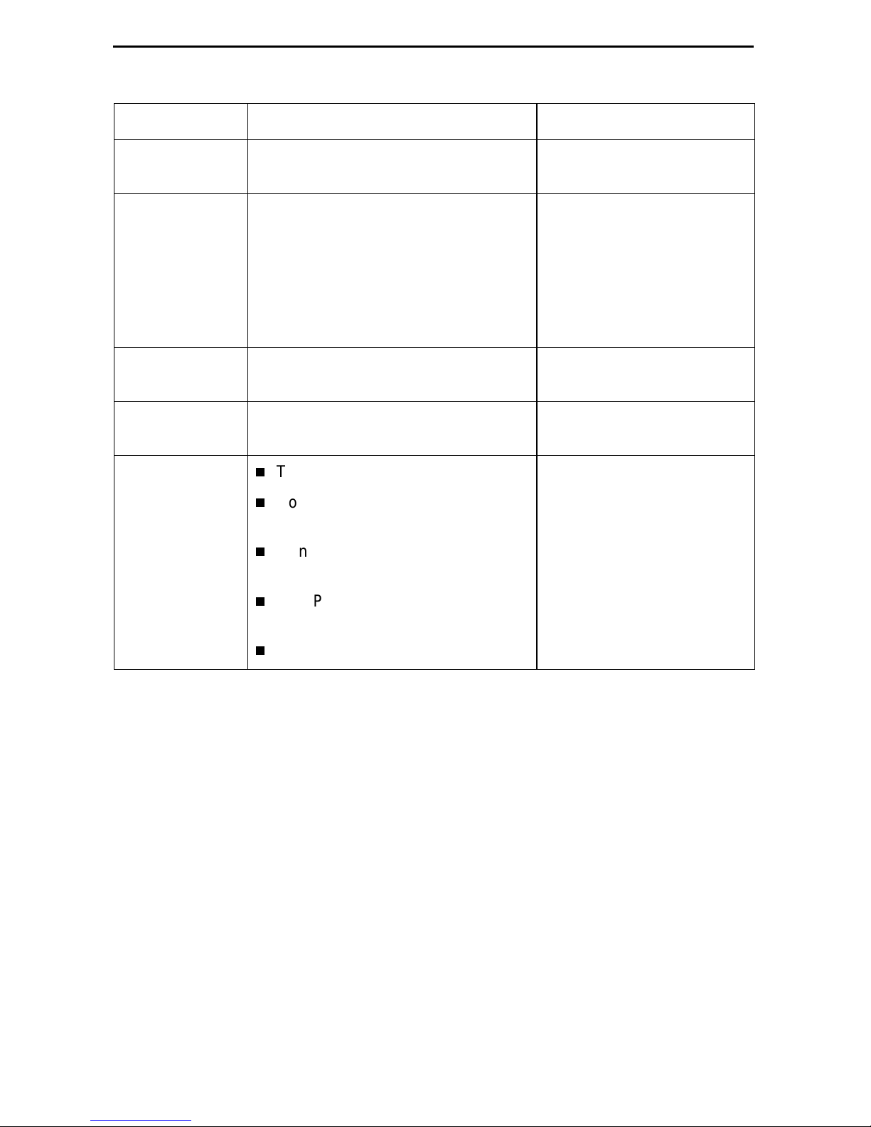
Select . . . To Access the . . . To Configure th e . . .
Network Network Interface Options (Table 1) DSL network interface on
the unit.
DSX-1
SYNC Port
G.703
DSX- 1 In te r fac e Op tio n s – Model
7974 (Table 2)
Synchronous Dat a Port Options –
Model 7975 (Table 3)
G.703 Inter face Options – Model
7976 (Table 4)
DSX-1 interface
(Model 7974)
Synchronous DTE interface
(Model 7975)
G.703 interface
(Model 7976)
System Options System Options (Table 5) General system options of
the unit.
Communication
Port
Management
and
Communication
Communica ti on Port Options
(Table 6)
Telnet Session Options (Table 7)
Communication Protocol Options
(Table 8)
General SNMP Managem ent
Unit’s COM port options.
Management support of the
unit through SNMP and
Telnet.
Options (Table 9)
SNMP NMS Security Options
(Table 10)
SNMP Traps Options (Table 11)
10

Table 1. Network Interface Options (1 of 2)
Margin Threshol d
Possible Settings: –5db, –4db, –3db, –2db, –1db, 0db, 1db, 2db, 3db, 4db, 5db,
6db, 7db, 8db, 9db, 10db
Default Sett ing: 0db
Determines the level, expressed in decibels, at which a signal-to-noise margin alarm
condition is reported.
Excessive Error Rate Threshold
Possible Settings: 1E–4, 1E–5, 1E–6 , 1E–7, 1E–8, 1E–9
Default Sett ing: 1E–6
Determines the error rate at which an excessive error rate (EER) condition is
recognized. The rate is the ratio of the number of CRC errors to the number of bits
receiv ed in a certain period.
AutoRate
Possible Settings: Enable, Disable
Default Sett ing: Disable
Determines whether the uni t aut om atically adjus ts t o the best line rate for conditions,
or is fixed at the rate in the DSL Line Rate field.
DSL Line Rate
Possible Settings (depends on model) : 144, 272, 400, 528, 784, 1040, 1552, 2064
Default Sett ing (Model 7974): 1552
Default Sett ing (Model 7975, 7976): 2064
Determines the fix ed line rate of the LTU when AutoRate is di sabled.
Max DSL AutoRate
Possible Settings (depends on model) : 144, 272, 400, 528, 784, 1040, 1552, 2064
Default Sett ing (Model 7974): 1552
Default Sett ing (Model 7975, 7976): 2064
Determines the maximum rate to which the unit can AutoRate.
11
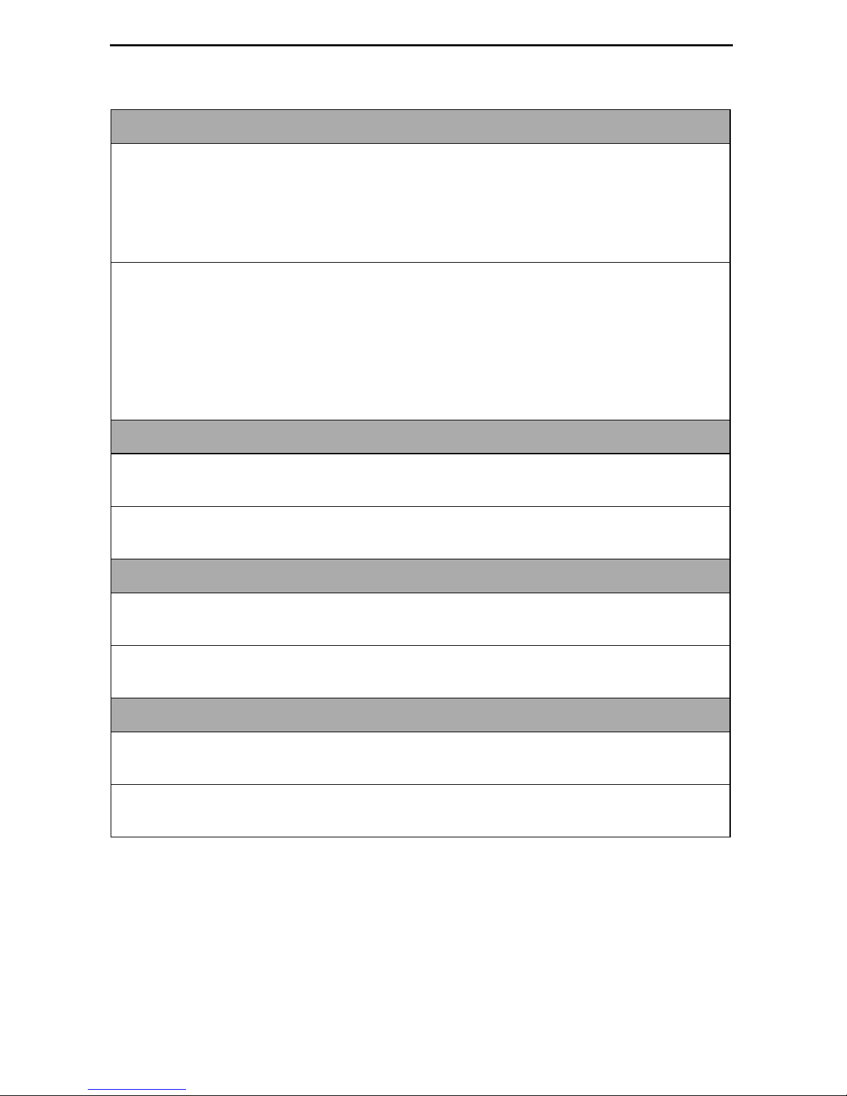
Table 1. Network Interface Options (2 of 2)
EIA-530 Pa yload Rate
Possible Settings (Model 7974) : 64, 128, 256, 384, 512, 768, 1024, 1536
Default Sett ing: [Highest multiple of 64 Kbps supported by the DSL Line Rate]
Possible Settings (Model 7976): 64, 128, 192, 256, 320, 384, 448, 512, 576, 640,
768, 960, 1024 , 1536, 1920, 1984, 2048
Default Sett ing: [Highest multiple of 64 Kbps supported by the DSL Line Rate]
When the NTU has an EIA-530-A interface, the Payload Rate set on the LTU
determines the port speed of the synchronous port of the NTU.
To achieve the payload rates listed above, th e Model 7975-A2 endpoint mus t be
operating wit h firmwar e V02.03. 2 or great er and the Model 7976-A2 endp oin t must be
operating with firmware N02.03.2 or greater. In lower firmware versions (N.02.03.05
and below), the pa yl oad rat e is only select ab le at a DSL line ra te of 144 Kbps while al l
other rates default to the maximum, dependi ng on the DSL line rate selected.
Transmit Attenuation
Possible Settings: 0dB – 15dB
Default Sett ing: 0dB
Determines how much the unit ’s transmit power is reduced to accommodate a short
line length.
Peer IP Address
Possible Settings: 001.000.000.000 – 223.255.255.255, Clear
Default Sett ing: 000.000.000.000
When configured as the LTU, specifies the peer IP addres s for the NTU, to provide
remote management providing the remot e man agem ent link on the DSL loop.
Circ ui t Id e n ti fier
Possible Settings:
ASCII text field
, Clear
Default Sett ing: [blank]
Uniquely identi fies the circuit num ber of the transmission vendor’s D S L li ne for
troubleshooting purposes.
12
 Loading...