

Paradyne 7925, HotWire 7925-A1 Owner's Manual
TM
3
HotWire 7925-A1 E1 HDSL Standalone Termination Unit
Errata
Document Number 7925-A2-GK40-10
September 1997
Errors and exclusions in the User’s Guide (Document No. 7925-A2-GB20-30) were detected after
printing. Please make note of the following corrections.
The following information should be included on page 1-1: Up to ten standalone units may be installed in
an optional HotWire 7900 10-slot Standalone Shelf, using a single power source. (The Standalone Shelf
is required for the –48 Vdc standalone model.)
The defaults shown on page A-2 are Terminal mode factory defaults. Switchpack mode defaults are
shown in this document.
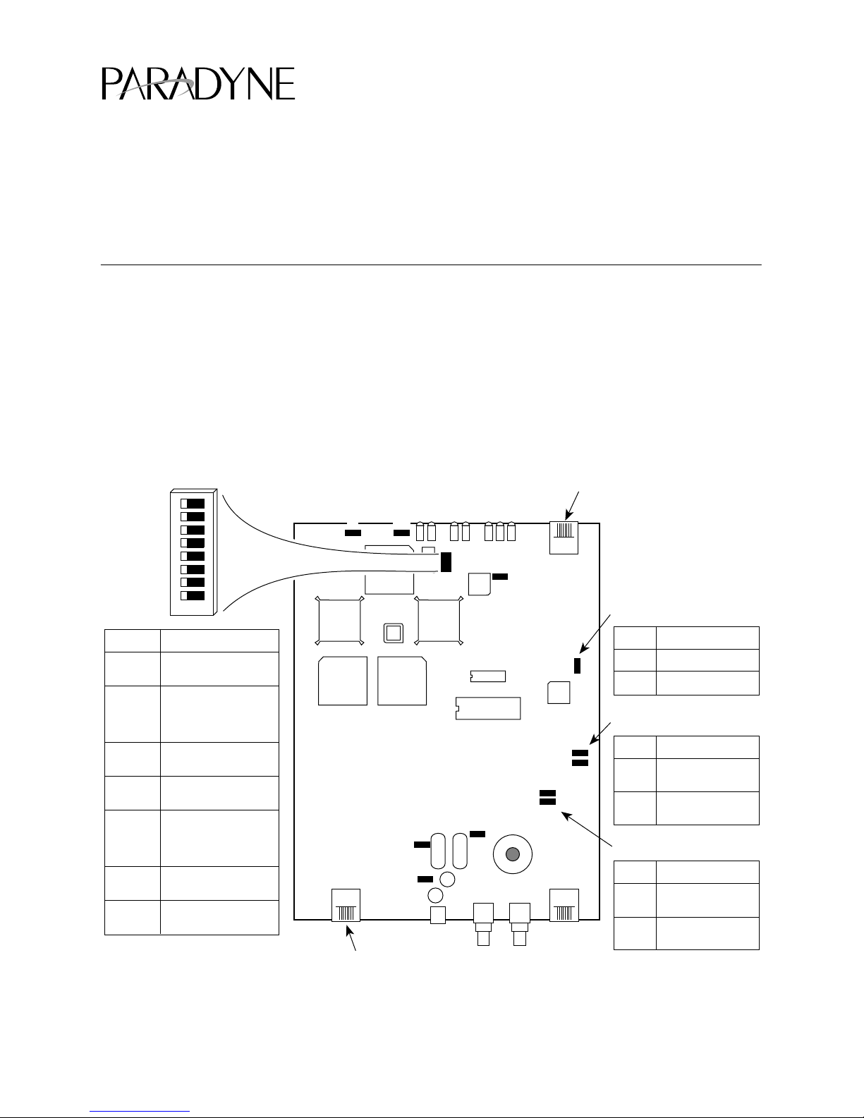
Use the following illustration rather than the one on page C-2:
Switchpack S1
Position
1
2
3
4
5
6, 7
8
* Default in bold
Settings*
OFF = CP
ON = CO
OFF = AMI line
encoding
ON = HDB3 line
encoding
OFF = Loops A and B
ON = Loop A
Must be OFF when
in Switchpack Mode
OFF = 75 ohm line
build-out
ON = 120 ohm line
build-out
Must be OFF when
in Switchpack Mode
OFF = Unframed
ON = Framed
ON
678
12345
P1
123 123
P10
P8
123
321
P9
HDSL Line Jack
VT100 Terminal
Modular Jack
S1
P3
12
Jumper P11
Pins*
Settings*
123
P11
1-2
Terminal Mode
2-3
Switchpack Mode
Jumpers P6, P7
123
P12
321
321
P6
P7
C31
C33
321
123
Pins*
Settings*
1-2
120 ohm line
build-out
2-3
75 ohm line
build-out
Jumpers C31, C33
Pins*
Settings*
1-2
75 ohm line
build-out
2-3
120 ohm line
build-out
97-15266-0
Figure C-1. G.703-Compatible Unit Switchpack and Jumper Locations
7925-A2-GK40-10
September 1997
1
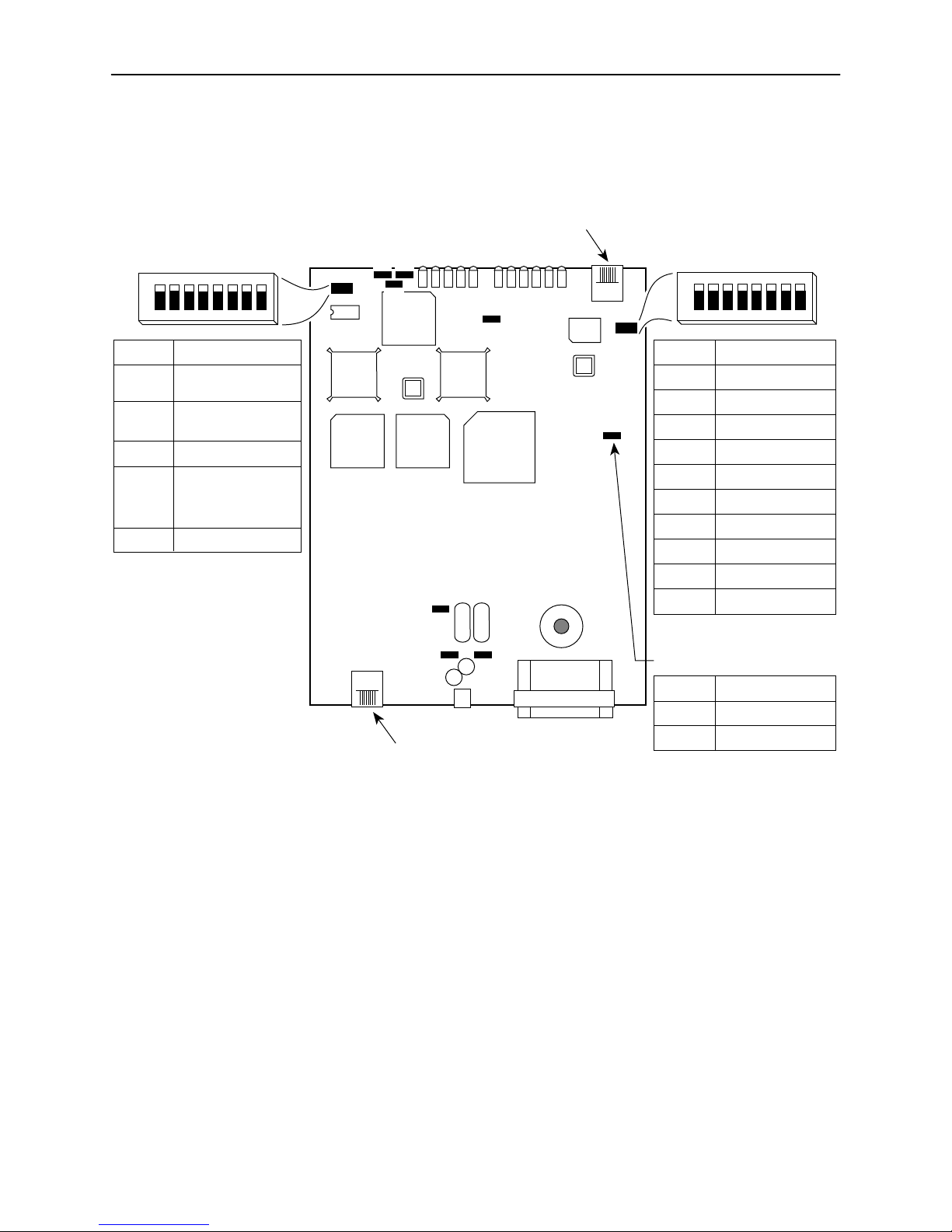
Use the following illustration rather than the one on page C-4:
4
VT100 Terminal
Modular Jack
Switchpack S1
ON
12345
Position
1
2
3
4, 5
6, 7, 8
* Default in bold
Settings*
OFF = CP
ON = CO
OFF = Loops A and B
ON = Loop A
unused
00 or 11 = Internal
Clock
01 = External Clock
10 = Loop Clock
unused
678
P1 P2
123 321
S1
123
HDSL Line Jack
Switchpack S2
P4
123
S2
P8
P9
123
321
P10
P5
123
12
P11
V.35
ON
12345
Position
1
2
3
4
5
6
7
8
Jumper P8
Pins*
1-2
2-3
678
Settings*
ON = 64 kbps
ON = 128 kbps
ON = 192 kbps
ON = 256 kbps
ON = 384 kbps
ON = 512 kbps
ON = 768 kbps
ON = 1024 kbps
All ON = 64 kbps
All OFF = 2048 kbps
Settings*
Terminal Mode
Switchpack Mode
97-15265-0
Figure C-2. V.35-Compatible Unit Switchpack and Jumper Locations
2
*7925–A2–GK40–10*
September 1997
7925-A2-GK40-10
 Loading...