

Page 1

MODEL 7610 SNMP DSU
USER’S GUIDE
Document No. 7610-A2-GB20-10
November 1997
Page 2

Copyright 1996 Paradyne Corporation.
All rights reserved.
Printed in U.S.A.
Notice
This publication is protected by federal copyright law. No part of this publication may be copied or distributed,
transmitted, transcribed, stored in a retrieval system, or translated into any human or computer language in any form
or by any means, electronic, mechanical, magnetic, manual or otherwise, or disclosed to third parties without the
express written permission of Paradyne Corporation, 8545 126th Avenue North, P.O. Box 2826, Largo,
Florida 33779-2826.
Paradyne Corporation makes no representation or warranties with respect to the contents hereof and specifically
disclaims any implied warranties of merchantability or fitness for a particular purpose. Further, Paradyne Corporation
reserves the right to revise this publication and to make changes from time to time in the contents hereof without
obligation of Paradyne Corporation to notify any person of such revision or changes.
Changes and enhancements to the product and to the information herein will be documented and issued as a new
release to this manual.
Trademarks
All products and services mentioned herein are the trademarks, service marks, registered trademarks or registered
service marks of their respective owners.
Warranty, Sales, and Service Information
Contact your sales or service representative directly for any help needed. For additional information concerning
warranty, service, repair, spare parts, installation, documentation, or training, use one of the following methods:
Via the Internet: Visit the Paradyne World Wide W eb site at http://www.paradyne.com
Via Telephone: Call our automated call system to receive current information via fax or to speak with a
company representative.
— Within the U.S.A., call 1-800-870-2221
— International, call 727-530-2340
Printed on recycled paper
A
November 1997
7610-A2-GB20-10
Page 3

Contents
About This Guide
Document Purpose and Intended Audience vii. . . . . . . . . . . . . . . . . . . . . . . . .
Document Summary vii. . . . . . . . . . . . . . . . . . . . . . . . . . . . . . . . . . . . . . . . . . . . .
Product-Related Documents viii. . . . . . . . . . . . . . . . . . . . . . . . . . . . . . . . . . . . . .
1 About the SNMP DSU
Model 7610 SNMP DSU Features 1-1. . . . . . . . . . . . . . . . . . . . . . . . . . . . . . . . .
SNMP Management Capabilities 1-2. . . . . . . . . . . . . . . . . . . . . . . . . . . . . . . . . .
MIB Support 1-2. . . . . . . . . . . . . . . . . . . . . . . . . . . . . . . . . . . . . . . . . . . . . . . .
Supported Link-Layer Protocols 1-3. . . . . . . . . . . . . . . . . . . . . . . . . . . . . . .
Typical SNMP DSU Configurations 1-3. . . . . . . . . . . . . . . . . . . . . . . . . . . . . . . .
User Interface Types 1-4. . . . . . . . . . . . . . . . . . . . . . . . . . . . . . . . . . . . . . . . . . . .
Rear Panel Interface Connections 1-4. . . . . . . . . . . . . . . . . . . . . . . . . . . . . . . . .
2 Using the ATI
Accessing the ATI 2-1. . . . . . . . . . . . . . . . . . . . . . . . . . . . . . . . . . . . . . . . . . . . . . .
Main Menu 2-2. . . . . . . . . . . . . . . . . . . . . . . . . . . . . . . . . . . . . . . . . . . . . . . . . . . . .
Screen Format Types 2-3. . . . . . . . . . . . . . . . . . . . . . . . . . . . . . . . . . . . . . . . . . . .
Navigating the Screens 2-5. . . . . . . . . . . . . . . . . . . . . . . . . . . . . . . . . . . . . . . . . .
Ending a Session 2-7. . . . . . . . . . . . . . . . . . . . . . . . . . . . . . . . . . . . . . . . . . . . . . .
Connecting to the Terminal Port 2-1. . . . . . . . . . . . . . . . . . . . . . . . . . . . . . .
What Affects Screen Displays 2-3. . . . . . . . . . . . . . . . . . . . . . . . . . . . . . . . .
Screen Work Areas 2-4. . . . . . . . . . . . . . . . . . . . . . . . . . . . . . . . . . . . . . . . . .
Keyboard Keys 2-5. . . . . . . . . . . . . . . . . . . . . . . . . . . . . . . . . . . . . . . . . . . . . .
Screen Function Keys 2-6. . . . . . . . . . . . . . . . . . . . . . . . . . . . . . . . . . . . . . . .
Switching Between Screen Work Areas 2-7. . . . . . . . . . . . . . . . . . . . . . . .
7610-A2-GB20-10
November 1997
i
Page 4

Contents
3 Customizing the SNMP DSU
Entering Device and System Information 3-1. . . . . . . . . . . . . . . . . . . . . . . . . . .
System Fields 3-2. . . . . . . . . . . . . . . . . . . . . . . . . . . . . . . . . . . . . . . . . . . . . . .
Identity Information 3-2. . . . . . . . . . . . . . . . . . . . . . . . . . . . . . . . . . . . . . . . . . . . . .
Configuring the DSU 3-3. . . . . . . . . . . . . . . . . . . . . . . . . . . . . . . . . . . . . . . . . . . .
Configuration Option Areas 3-3. . . . . . . . . . . . . . . . . . . . . . . . . . . . . . . . . . .
Accessing and Displaying Configuration Options 3-4. . . . . . . . . . . . . . . .
Saving Configuration Options 3-4. . . . . . . . . . . . . . . . . . . . . . . . . . . . . . . . .
Establishing Call Setup 3-5. . . . . . . . . . . . . . . . . . . . . . . . . . . . . . . . . . . . . . . . . .
Call Directories Screen 3-5. . . . . . . . . . . . . . . . . . . . . . . . . . . . . . . . . . . . . . .
Call Setup Screen 3-7. . . . . . . . . . . . . . . . . . . . . . . . . . . . . . . . . . . . . . . . . . .
4 Security
Security Overview 4-1. . . . . . . . . . . . . . . . . . . . . . . . . . . . . . . . . . . . . . . . . . . . . . .
Creating a Login 4-2. . . . . . . . . . . . . . . . . . . . . . . . . . . . . . . . . . . . . . . . . . . . .
Deleting a Login 4-3. . . . . . . . . . . . . . . . . . . . . . . . . . . . . . . . . . . . . . . . . . . . .
A TI Access 4-4. . . . . . . . . . . . . . . . . . . . . . . . . . . . . . . . . . . . . . . . . . . . . . . . .
Effective Access Level 4-4. . . . . . . . . . . . . . . . . . . . . . . . . . . . . . . . . . . . . . .
Controlling SNMP Access 4-6. . . . . . . . . . . . . . . . . . . . . . . . . . . . . . . . . . . . . . . .
Assigning SNMP Community Names and Access Levels 4-6. . . . . . . . .
Limiting SNMP Access through the IP Addresses
of the Managers 4-6. . . . . . . . . . . . . . . . . . . . . . . . . . . . . . . . . . . . . . . . . . . . .
5 IP Addressing
Selecting an IP Addressing Scheme 5-1. . . . . . . . . . . . . . . . . . . . . . . . . . . . . . .
IP Addressing Scheme Examples 5-2. . . . . . . . . . . . . . . . . . . . . . . . . . . . . . . . .
Assigning IP Addresses and Subnet Masks 5-4. . . . . . . . . . . . . . . . . . . . . . . . .
Choosing a Default Network Destination 5-4. . . . . . . . . . . . . . . . . . . . . . . . . . .
IMC Connection – Same Subnet 5-2. . . . . . . . . . . . . . . . . . . . . . . . . . . . . .
Using Routers to Route DSU Management Data 5-3. . . . . . . . . . . . . . . . .
ii
November 1997
7610-A2-GB20-10
Page 5

6 Monitoring the DSU
What to Monitor 6-1. . . . . . . . . . . . . . . . . . . . . . . . . . . . . . . . . . . . . . . . . . . . . . . . .
DSU LEDs 6-1. . . . . . . . . . . . . . . . . . . . . . . . . . . . . . . . . . . . . . . . . . . . . . . . . . . . .
System LEDs 6-2. . . . . . . . . . . . . . . . . . . . . . . . . . . . . . . . . . . . . . . . . . . . . . .
Network LEDs 6-3. . . . . . . . . . . . . . . . . . . . . . . . . . . . . . . . . . . . . . . . . . . . . .
Port LEDs 6-4. . . . . . . . . . . . . . . . . . . . . . . . . . . . . . . . . . . . . . . . . . . . . . . . . .
Unit Status 6-5. . . . . . . . . . . . . . . . . . . . . . . . . . . . . . . . . . . . . . . . . . . . . . . . . . . . .
Viewing Health and Status 6-5. . . . . . . . . . . . . . . . . . . . . . . . . . . . . . . . . . . .
Self-Test Results 6-7. . . . . . . . . . . . . . . . . . . . . . . . . . . . . . . . . . . . . . . . . . . .
Network Interface Status 6-7. . . . . . . . . . . . . . . . . . . . . . . . . . . . . . . . . . . . . . . . .
Network Performance Statistics 6-8. . . . . . . . . . . . . . . . . . . . . . . . . . . . . . . . . . .
7 T esting
Detecting Problems 7-1. . . . . . . . . . . . . . . . . . . . . . . . . . . . . . . . . . . . . . . . . . . . .
Tests Available 7-2. . . . . . . . . . . . . . . . . . . . . . . . . . . . . . . . . . . . . . . . . . . . . . . . .
Network Tests 7-2. . . . . . . . . . . . . . . . . . . . . . . . . . . . . . . . . . . . . . . . . . . . . . . . . .
CSU or External Network Loopback 7-3. . . . . . . . . . . . . . . . . . . . . . . . . . . .
DSU or Internal Network Loopback 7-3. . . . . . . . . . . . . . . . . . . . . . . . . . . .
Send V.54 Up/Down Sequences 7-3. . . . . . . . . . . . . . . . . . . . . . . . . . . . . . .
511 Test Pattern for the Network 7-4. . . . . . . . . . . . . . . . . . . . . . . . . . . . . . .
Data Port Tests 7-4. . . . . . . . . . . . . . . . . . . . . . . . . . . . . . . . . . . . . . . . . . . . . . . . .
Local Loopback 7-4. . . . . . . . . . . . . . . . . . . . . . . . . . . . . . . . . . . . . . . . . . . . .
511 Test Pattern for the DTE 7-4. . . . . . . . . . . . . . . . . . . . . . . . . . . . . . . . . .
Lamp Test 7-4. . . . . . . . . . . . . . . . . . . . . . . . . . . . . . . . . . . . . . . . . . . . . . . . . . . . . .
Ending an Active Test 7-5. . . . . . . . . . . . . . . . . . . . . . . . . . . . . . . . . . . . . . . . . . . .
Test Status Messages 7-5. . . . . . . . . . . . . . . . . . . . . . . . . . . . . . . . . . . . . . . . . . .
Loopbacks 7-6. . . . . . . . . . . . . . . . . . . . . . . . . . . . . . . . . . . . . . . . . . . . . . . . . . . . .
Device Reset 7-7. . . . . . . . . . . . . . . . . . . . . . . . . . . . . . . . . . . . . . . . . . . . . . . . . . .
Contents
8 Messages and Troubleshooting
Messages and Troubleshooting 8-1. . . . . . . . . . . . . . . . . . . . . . . . . . . . . . . . . . .
Alarm Messages 8-1. . . . . . . . . . . . . . . . . . . . . . . . . . . . . . . . . . . . . . . . . . . . . . . .
ASCII Alarms 8-1. . . . . . . . . . . . . . . . . . . . . . . . . . . . . . . . . . . . . . . . . . . . . . .
ASCII Alarm Messages 8-2. . . . . . . . . . . . . . . . . . . . . . . . . . . . . . . . . . . . . . .
Configuring SNMP Traps 8-3. . . . . . . . . . . . . . . . . . . . . . . . . . . . . . . . . . . . .
Dialing Out SNMP Traps 8-3. . . . . . . . . . . . . . . . . . . . . . . . . . . . . . . . . . . . .
Device Messages 8-4. . . . . . . . . . . . . . . . . . . . . . . . . . . . . . . . . . . . . . . . . . . . . . .
Troubleshooting 8-5. . . . . . . . . . . . . . . . . . . . . . . . . . . . . . . . . . . . . . . . . . . . . . . . .
7610-A2-GB20-10
November 1997
iii
Page 6

Contents
A Configuration Option Tables
Configuration Option Tables Overview A-1. . . . . . . . . . . . . . . . . . . . . . . . . . . . .
System Options Menu A-2. . . . . . . . . . . . . . . . . . . . . . . . . . . . . . . . . . . . . . . . . . .
Network Interface Options Menu A-5. . . . . . . . . . . . . . . . . . . . . . . . . . . . . . . . . .
Data Port Options Menu A-9. . . . . . . . . . . . . . . . . . . . . . . . . . . . . . . . . . . . . . . . .
User Interface Options Menu A-11. . . . . . . . . . . . . . . . . . . . . . . . . . . . . . . . . . . . .
Terminal Port Options A-11. . . . . . . . . . . . . . . . . . . . . . . . . . . . . . . . . . . . . . . .
Management Port Options A-13. . . . . . . . . . . . . . . . . . . . . . . . . . . . . . . . . . . .
External Device Options for the Management Port A-15. . . . . . . . . . . . . . .
Telnet Session Options A-18. . . . . . . . . . . . . . . . . . . . . . . . . . . . . . . . . . . . . . .
Alarms & Traps Options Menu A-20. . . . . . . . . . . . . . . . . . . . . . . . . . . . . . . . . . . .
SNMP & Communication Options Menu A-22. . . . . . . . . . . . . . . . . . . . . . . . . . . .
Communication Protocol Options A-22. . . . . . . . . . . . . . . . . . . . . . . . . . . . . .
General SNMP Management Options A-24. . . . . . . . . . . . . . . . . . . . . . . . . .
SNMP NMS Security Options A-25. . . . . . . . . . . . . . . . . . . . . . . . . . . . . . . . .
SNMP Traps Options A-27. . . . . . . . . . . . . . . . . . . . . . . . . . . . . . . . . . . . . . . .
ASCII Characters A-29. . . . . . . . . . . . . . . . . . . . . . . . . . . . . . . . . . . . . . . . . . . . . . .
B W orksheets
Overview B-1. . . . . . . . . . . . . . . . . . . . . . . . . . . . . . . . . . . . . . . . . . . . . . . . . . . . . .
Configuration Worksheets B-1. . . . . . . . . . . . . . . . . . . . . . . . . . . . . . . . . . . . . . . .
C MIB Descriptions
MIB Description Overview C-1. . . . . . . . . . . . . . . . . . . . . . . . . . . . . . . . . . . . . . . .
MIB II – RFC 1213 and RFC 1573 C-1. . . . . . . . . . . . . . . . . . . . . . . . . . . . .
RS-232-Like MIB – RFC 1659 C-2. . . . . . . . . . . . . . . . . . . . . . . . . . . . . . . . .
Enterprise MIB Objects C-2. . . . . . . . . . . . . . . . . . . . . . . . . . . . . . . . . . . . . . .
System Group C-3. . . . . . . . . . . . . . . . . . . . . . . . . . . . . . . . . . . . . . . . . . . . . .
RS-232-Like MIB, RFC 1659 C-13. . . . . . . . . . . . . . . . . . . . . . . . . . . . . . . . . .
Enterprise MIB Objects C-18. . . . . . . . . . . . . . . . . . . . . . . . . . . . . . . . . . . . . . .
D Standards Compliance for SNMP Traps
SNMP Traps Overview D-1. . . . . . . . . . . . . . . . . . . . . . . . . . . . . . . . . . . . . . . . . . .
Trap: authentificationFailure D-1. . . . . . . . . . . . . . . . . . . . . . . . . . . . . . . . . .
Trap: warmStart D-2. . . . . . . . . . . . . . . . . . . . . . . . . . . . . . . . . . . . . . . . . . . . .
Traps: linkUp and linkDown D-2. . . . . . . . . . . . . . . . . . . . . . . . . . . . . . . . . . .
Traps: Enterprise Specific D-3. . . . . . . . . . . . . . . . . . . . . . . . . . . . . . . . . . . . . . . .
iv
November 1997
7610-A2-GB20-10
Page 7

E Cables and Pin Assignments
Cabling Overview E-1. . . . . . . . . . . . . . . . . . . . . . . . . . . . . . . . . . . . . . . . . . . . . . .
Terminal Port EIA-232 Connector E-2. . . . . . . . . . . . . . . . . . . . . . . . . . . . . . . . .
Management Port EIA-232 Connector E-2. . . . . . . . . . . . . . . . . . . . . . . . . . . . .
V.35 User Data Port Connector E-3. . . . . . . . . . . . . . . . . . . . . . . . . . . . . . . . . . .
Standard EIA-232-D Crossover Cable E-4. . . . . . . . . . . . . . . . . . . . . . . . . . . . .
LAN Adapter Converter and Cable E-5. . . . . . . . . . . . . . . . . . . . . . . . . . . . . . . .
Modular RJ48S DDS Network Interface Cable E-5. . . . . . . . . . . . . . . . . . . . . .
Glossary
Index
Contents
7610-A2-GB20-10
November 1997
v
Page 8

About This Guide
Document Purpose and Intended Audience
This guide contains information needed to set up, configure, and operate the
Model 7610 SNMP DSU and is intended for installers and operators.
Document Summary
Section Description
Chapter 1
Chapter 2
Chapter 3
Chapter 4
Chapter 5
Chapter 6
Chapter 7
Chapter 8
About the SNMP DSU.
SNMP management capabilities with a typical configuration
example.
Using the ATI.
interface and navigating the screens.
Customizing the SNMP DSU.
setting up the user interface, device information, call setup,
and DSU configuration steps.
Security.
the effective access levels, and controlling SNMP access.
IP Addressing.
examples.
Monitoring the DSU.
LEDs, DSU status, and network statistics.
Testing.
setup.
Messages and Troubleshooting.
ASCII alarms, SNMP traps, device messages, and
troubleshooting.
Presents procedures for creating a login, setting
Provides details about available tests and test
Describes the DSU features and
Provides instructions for accessing the user
Provides procedures for
Provides details regarding IP addresses with
Describes monitoring details about the
Provides information on
7610-A2-GB20-10
November 1997
vii
Page 9

About This Guide
Section Description
Appendix A
Appendix B
Appendix C
Appendix D
Appendix E
Glossary Defines acronyms and terms used in this document.
Index Lists key terms, acronyms, concepts, and sections in
Product-Related Documents
Document Number Document Title
7610-A2-GN10
Configuration Option Tables.
options, default settings, and possible settings.
Worksheets.
settings, and possible settings to use for planning.
MIB Descriptions.
Standards Compliance for SNMP Traps.
trap compliance details.
Cables and Pin Assignments.
interface details.
alphabetical order.
Contains all the configuration options, default
Provides all MIBs supported by the DSU.
Model 7610 SNMP DSU Startup Instructions
Contains all configuration
Contains SNMP
Contains connector and
To order additional product documentation, refer to the
Service Information
section on page A at the beginning of this User’s Guide.
Warranty, Sales, and
viii
November 1997
7610-A2-GB20-10
Page 10

About the SNMP DSU
Model 7610 SNMP DSU Features
The SNMP DSU provides an interface between the customer premises
equipment (CPE) and a DDS network. Its features include:
SNMP (Simple Network Management Protocol) Management. Provides
network management via an industry-standard SNMP management system.
In-band Management Channel (IMC). Provides remote management via
SNMP or Telnet session capability over the DDS network.
1
Async Terminal Interface (ATI). Provides a menu-driven VT100-compatible
interface for configuring and managing the DSU locally or remotely by Telnet
session or External Modem.
Local Management. Provides local management via an:
— Async terminal connection through the Terminal port
— NMS connection through the Management port
Remote Management. Provides remote management:
— Out-of-band, using an external modem through the Terminal port or
Management port
— Via Telnet through the Management port or the In-band Management
Channel (IMC)
DDS Rates. Operates at 56 and 64 kbps CC (clear channel).
LADS Operation (Local Area Data Set). Operates at 56 and 64 kbps
full-duplex (also called a limited distance modem).
Autorating of Line Rate. Establishes the line rate from the network receive
signal and automatically adjusts to the detected line rate.
Data Port Rates. Supports the same rates as the DDS or LADS operating
rates, except when the IMC is enabled.
7610-A2-GB20-10
November 1997
1-1
Page 11
About the SNMP DSU
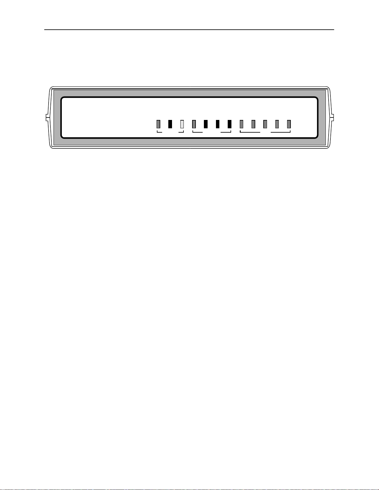
Alarm Indication. Activates front panel LEDs and provides the capability of
attaching an ASCII terminal or printer to display/print alarm messages.
7610 SNMP DSU
OK
ALARM
56/64K
Diagnostics. Provides the capability to diagnose device and network
problems and perform tests, including digital loopbacks, pattern tests, and
self-test.
Device and Test Monitoring. Provides the capability of tracking and
evaluating the unit’s operation, including health and status, and error-rate
monitoring.
Two Customer-Specified Configuration Storage Areas. Allows quick
access to alternate sets of configuration options.
Security. Provides multiple levels of security, which prevents unauthorized
access to the DSU.
SNMP Management Capabilities
The DSU supports SNMP Version 1, and has the capability of being managed by
any industry-standard SNMP manager and accessed using SNMP protocol by
external SNMP managers.
TEST
DM
OOS
NetworkSystem
OOF
NS
TXD (103)
RXD (104)
RTS (105)
Port
CTS (106)
DTR (108)
496-15073
MIB Support
1-2
The following MIBs are supported:
MIB II (RFC 1213 and RFC 1573) – Defines the general objects for use with
a network management protocol in TCP/IP internets and provides general
information about the DSU. MIB II is backward-compatible with MIB I.
RS-232-Like MIB (RFC 1659) – Defines objects for managing RS-232-type
interfaces (e.g., V.35, RS-422, RS-423, etc.) and supports synchronous data
ports and management communication ports on the DSU.
Enterprise MIB – Supports configuration, status, statistics, and tests on the
DDS network interface.
November 1997
7610-A2-GB20-10
Page 12
Supported Link-Layer Protocols
The DSU supports two link-layer protocols for connection to an external SNMP
manager or network device:
Point-to-Point Protocol (PPP)
Serial Line Internet Protocol (SLIP)
Typical SNMP DSU Configurations
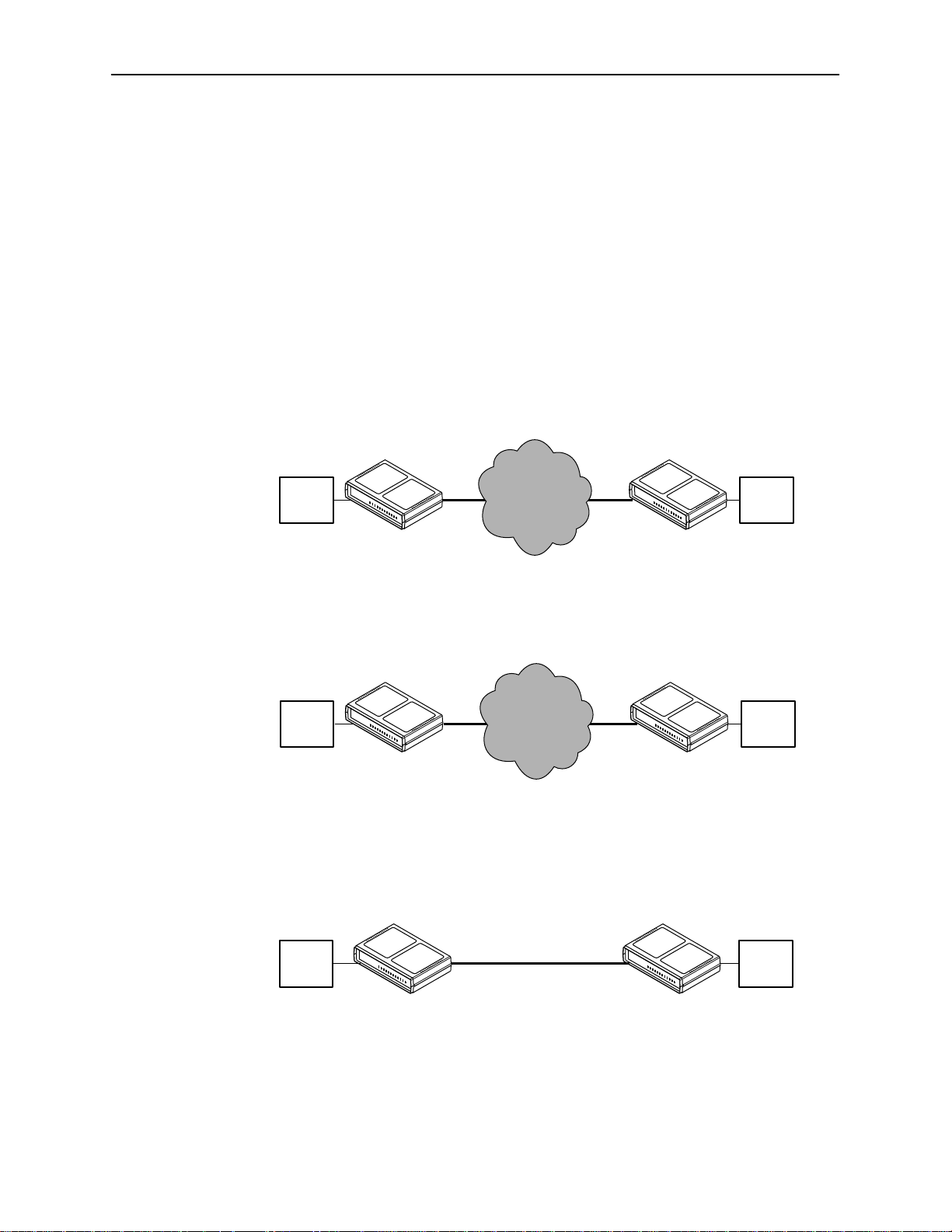
The following illustration shows a typical LAN/WAN interconnection application for
the DSU. The routers connected to the DSU at each location provide the LAN
interconnection.
About the SNMP DSU
Digital
Data
Network
DDS
SNMP
DSU
Router
497-15274
Router
DDS
SNMP
DSU
The SNMP DSU can also be used in a frame relay network.
Frame
Relay
Network
DDS
SNMP
DSU
Router
497-15275
Router
DDS
SNMP
DSU
Two SNMP DSUs can be connected back-to-back to act as Local Area Data Sets.
Table 3 in the
Model 7610 DSU Startup Instructions
shows the maximum
distances for LADS applications.
7610-A2-GB20-10
Router
SNMP
DSU
November 1997
56 Kbps
or
64 Kbps
SNMP
DSU
Router
497-15276
1-3
Page 13
About the SNMP DSU
User Interface Types
There are three types of user interfaces for the SNMP DSU:
Menu-driven async terminal interface screens (see
SNMP NMS Access – Refer to the
the capability to access the DSU via an SNMP management system
connected to the Management port or remotely through the in-band
management channel (IMC) connection. Refer to
Front panel LED status indicators. Refer to
Rear Panel Interface Connections
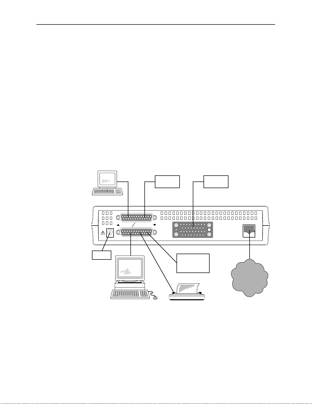
The following illustration shows the physical interfaces of the DSU. Information
about the installation of the DSU is contained in the
Instructions
Terminal
.
or
Modem
Using the ATI
SNMP DSU Features
IP Addressing
Monitoring the DSU
Model 7610 DSU Startup
DTE
, Chapter 2).
section. Provides
, Chapter 5.
, Chapter 6.
Power
TERMINAL MANAGEMENT
POWER
NMS Host
or or
Router,
LAN Adapter,
or Modem
ASCII Terminal
or Printer
D
T
E
NETWORK
Network
496-15085
1-4
November 1997
7610-A2-GB20-10
Page 14

Using the ATI
Accessing the ATI
You can communicate with the Asynchronous Terminal Interface (ATI) using one
of the following methods:
Direct connection through the Terminal port.
Dialing in through an external modem to the Terminal port.
Telnet session through the Management port (locally or via an external
2
modem).
Telnet session through the In-band Management Channel (IMC).
NOTE:
Only one asynchronous user interface session can be active at a time, and
another user’s session cannot be forced to end. To automatically log out a
user due to inactivity, enable the Inactivity Timeout option (see Terminal Port
Options, Table A-4).
The user interface is blank until activated. Press Return to activate the user
interface. Security can limit ATI access several ways. To setup security or a login
ID, refer to
Connecting to the Terminal Port
Verify that the settings of the device that you connect to the Terminal port match
these factory-loaded option default settings:
Data rate set to 9.6 kbps.
Character length set to 8.
Parity set to None.
Stop Bits set to 1.
Security
, Chapter 4.
7610-A2-GB20-10
To change the Terminal Port settings, refer to Terminal Port Options, Table A-4.
November 1997
2-1
Page 15
Using the ATI
Main Menu
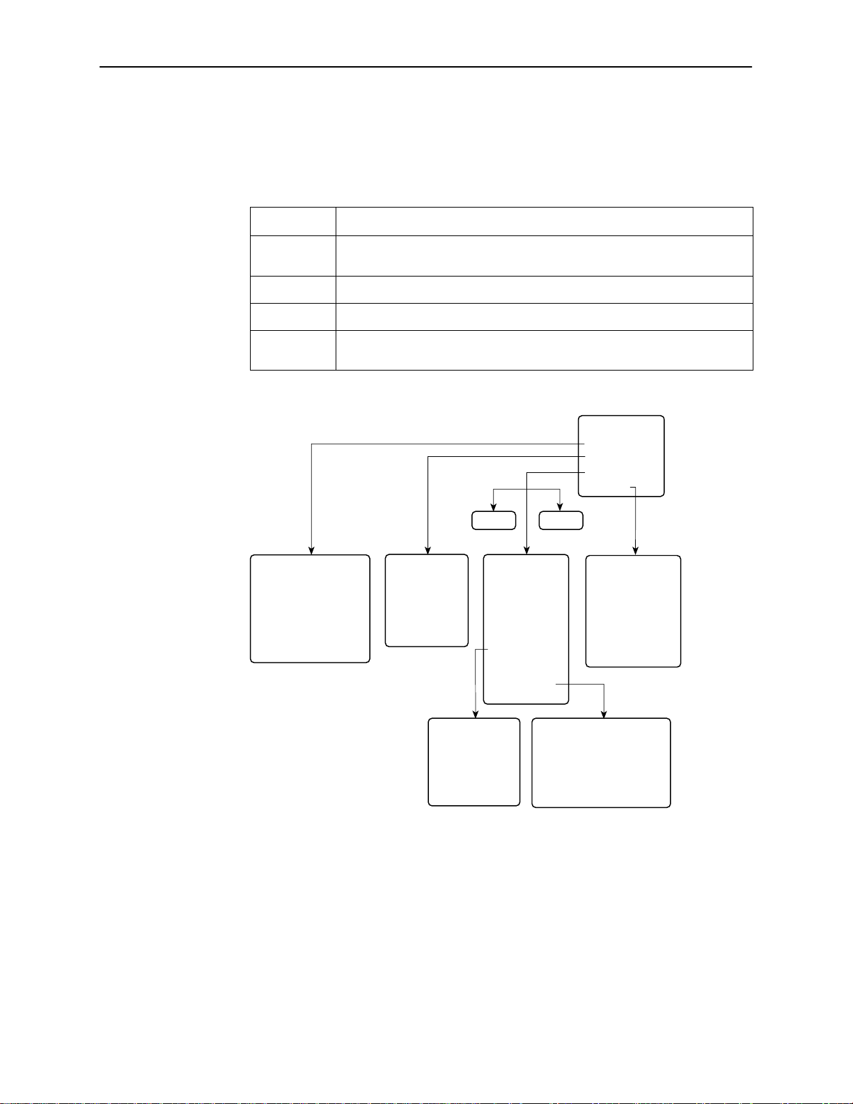
Entry to all of the DSU’s tasks begins at the Main Menu screen, which has four
menus or branches.
Select . . .
To . . .
Status View diagnostic tests, network status of interfaces, statistics, LEDs, and
DSU identity information.
Test Select and cancel tests for the DSU’s interfaces.
Configuration Display and edit the configuration options.
Control Control the user interface for call setup, device naming, and login
administration, or to initiate a power-up reset of the DSU.
MAIN MENU
Status
Test
Configuration
Control
SaveLoad
Status
• System and Test Status
• Network Interface Status
• Performance Statistics
• Display LEDs
• Identity
Test
• Network T ests
• Data Port Tests
• Lamp Test
• Abort All Tests
Configuration
Edit/Display
• System
• Network
• Data Port
• User Interface
• Alarms & Traps
• SNMP &
Communication
Control
• Call Setup
• Call Directories
• Device Name
• Administer Logins
• Reset Device
2-2
User Interface
• T erminal Port
• Management Port
• External Device
• T elnet Session
November 1997
SNMP & Communication
• Communication Protocol
• General SNMP Management
• SNMP NMS Security
• SNMP Traps
496-14999-01
7610-A2-GB20-10
Page 16

Screen Format Types
Three types of screen formats are available on the ATI.
Using the ATI
Use the screen format . . .
Menu selection Display a list of available functions for user selection.
Input Add or change information on a screen.
Display Display configuration information and results from
What Affects Screen Displays
What appears on the screens depends on the:
Current configuration – How your DSU is currently configured.
Effective security access level – An access level that is typically set by the
system administrator for each interface and each user.
Data selection criteria – What you entered in previous screens.
To . . .
Input or edit fields that have an Underline
or selection. See
performance and DSU-specific tests.
Display-only fields that have no underline in the field value.
Screen Work Areas
in the field value
.
7610-A2-GB20-10
November 1997
2-3
Page 17
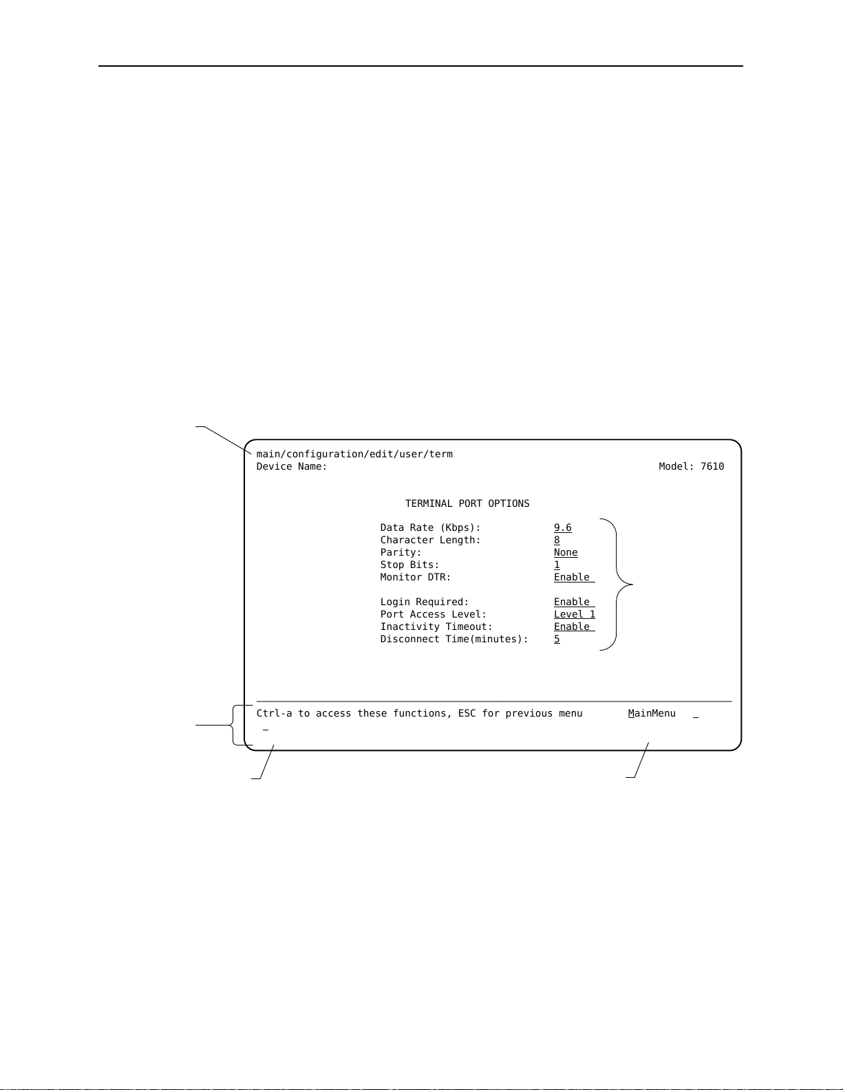
Using the ATI
Screen Work Areas
Menu Path
There are two user work areas:
Screen area – Provides the menu path, access level, menus, and input fields
above the dotted line. Refer to
Entering Device and System Information
in
Chapter 3.
The menu path appears as the first line on the screen. In this manual, the
menu path is presented as a menu selection sequence with the names of the
screens:
Main Menu→Configuration→Load Configuration From→ Edit
→
User Interface→Terminal Port
Screen function key area – Provides functions available below the dotted
line based upon screen selection and access level. Refer to the
Between Screen Work Areas
main/configuration/edit/user/term
Device Name: Model: 7610
section.
Switching
Screen
Function
Keys
Field V alue
Choices
TERMINAL PORT OPTIONS
Data Rate (Kbps): 9.6
Character Length: 8
Parity: None
Stop Bits: 1
Monitor DTR: Enable
Login Required: Enable
Port Access Level: Level 1
Inactivity Timeout: Enable
Disconnect Time(minutes): 5
––––––––––––––––––––––––––––––––––––––––––––––––––––––––––––––––––––––––––––––––
Ctrl-a to access these functions, ESC for previous menu M
S
ave
Select: 2.4, 4.8, 9.6, 14.4, 19.2, 28.8, 38.4 No Signal
Input Fields
ainMenu Exit
System
Messages
2-4
November 1997
7610-A2-GB20-10
Page 18

Navigating the Screens
You can navigate the screens by:
H Using keyboard keys
H Using screen function keys
H Switching between the two screen work areas
Keyboard Keys
Use the following keyboard keys to navigate within the screen.
Using the ATI
To . . .
Move cursor between the screen area and the screen function
keys area below the dotted line at the bottom of the screen
Return to the previous screen Esc
Move cursor to the next field on the screen Tab
Accept entry or display valid options on the last row of the screen
when pressed before entering data or after entering invalid data
Move cursor one position to the left Ctrl-k
Select the next valid value for the field Spacebar
Delete character that the cursor is on Delete (Del)
Move cursor up one field within a column on the same screen Up Arrow or Ctrl-u
Move cursor down one field within a column on the same screen Down Arrow or Ctrl-d
Move cursor one character to the right if in edit mode Right Arrow or Ctrl-f
Move cursor one character to the left if in edit mode Left Arrow or Ctrl-b
Redraw the screen display , clearing information typed in but not
yet entered
Press . . .
Ctrl-a
Return (Enter)
Ctrl-l
7610-A2-GB20-10
To make a menu or field selection:
" Procedure
1. Press the tab key or the right arrow key to position the cursor on a menu or
field selection. Each selection is highlighted as you press the key to move the
cursor from position to position.
2. Press Return. The selected menu or screen appears.
3. Continue Steps 1 and 2 until you reach the screen you want.
November 1997
2-5
Page 19

Using the ATI
Screen Function Keys
The current setting or value appears to the right of the field name. You can enter
information into a selected field by:
Typing in the first letter(s) of a field value or command, using the DSU’s
character matching feature.
Switching from the screen area to the screen function area below the dotted
line and selecting or entering the designated screen function key.
If a field is blank and the Field Values screen area displays valid selections, press
the spacebar and the first valid value for the field will appear. Continue pressing
the spacebar to scroll through other valid values.
All screen function keys located below the dotted line operate the same way
(upper- or lowercase) throughout the screens.
For the screen
function . . .
Select . . . And press Return to . . .
MainMenu M or m Return to the Main Menu screen.
Exit E or e Terminate the async terminal session.
New N or n Enter new data.
Modify O or o Modify existing data.
Delete L or l Delete data.
Save S or s Save information.
Refresh R or r Update screen with current information.
Clear C or c Clear status messages for one-time events on the System
and Test Status screen.
ClrStats C or c Clear statistics and refresh the Network Performance
Statistics screen.
PgUp U or u Display the previous page.
PgDn D or d Display the next page.
ResetMon R or r Reset an active Monitor 511 test counter to zero.
2-6
November 1997
7610-A2-GB20-10
Page 20

Switching Between Screen Work Areas
Selecting Ctrl-a allows you to switch between the two screen work areas to
perform all screen functions. To access the screen function area below the dotted
line:
Procedure
1. Press Ctrl-a to switch from the screen area to the screen function key area
below the dotted line. The available selections for the first input field appear
on the last line as shown below.
2. Select either the function’s designated (underlined) character or press the tab
key until you reach the desired function key.
Example:
To leave the current screen, enter e or E (Exit).
3. Press Return. The function is performed.
4. To return to the screen area above the dotted line, press Ctrl-a again.
Using the ATI
Ending a Session
Procedure
main/configuration/edit/user/mgmt
Device Name: Model: 7610
MANAGEMENT PORT OPTIONS
Port Use: Net Link
Port Type: Synchronous
Clock Source: Internal
Data Rate(Kbps): 9.6
Routing Information Protocol:None
––––––––––––––––––––––––––––––––––––––––––––––––––––––––––––––––––––––––––––––––
Ctrl-a to access these functions, ESC for previous menu M
ave
S
Select: None, Net Link, Alarms.
ainMenu Exit
Use the Exit function key from any screen to terminate the session.
1. Press Ctrl-a to go to the screen function key area below the dotted line.
7610-A2-GB20-10
2. Save changes if you have altered your configuration.
3. Select E
xit and press Return. The Main Menu appears.
November 1997
2-7
Page 21

Customizing the SNMP DSU
Entering Device and System Information
Use the Device Name screen to input DSU device and SNMP system entries. To
access the Device Name screen, follow this menu selection sequence:
Main Menu→Control→Device Name
main/control/device name
Device Name: Model: 7610
3
DEVICE NAME
Device Name: NE815378
System Name: lllQJ98-001
System Location: Bldg. A412, 2nd Floor, Left cabinet
System Contact: Joe Smith 800-555-5555 pager 888-555-5555 Clear
––––––––––––––––––––––––––––––––––––––––––––––––––––––––––––––––––––––––––––––––
Ctrl-a to access these functions, ESC for previous menu M
S
ave
Any printable ASCII characters are valid entries for all the Device Name screen
inputs. Refer to the
field is alphanumeric and provides for an input of 20 characters. The Device
Name entry appears on all ATI screens. The input on this screen is displayed on
the Identity screen. Refer to the
ASCII Characters
Identity Information
section in Appendix A. The Device Name
section.
Clear
Clear
Clear
ainMenu Exit
7610-A2-GB20-10
November 1997
3-1
Page 22

Customizing the SNMP DSU
System Fields
The three System entry fields are alphanumeric and provide 127 characters for
each field. The System entries appear on the Identity display as shown in the
next section. The SNMP System entry fields are:
System Name: The general SNMP system name
System Location: The physical location of the SNMP managed device
System Contact: Identification information, such as contact name, phone
number, or mailing address
Press Ctrl-a to switch to the screen function key area below the dotted line.
Select S
appears at the bottom of the screen.
Identity Information
The Identity screen provides identification information about the DSU. To view
information on the three System entries beyond the 40 characters on the screen,
place the cursor on the first or last character and press the left or right arrow.
ave and press Return. When Save is complete, Command Complete
To access the Identity screen, follow this menu selection sequence:
Main Menu→Status→Identity
main/status/identity
Device Name: NE815378 Model: 7610
IDENTITY
System Name: lllQJ98-001
System Location: Bldg. A412, 2nd Floor, Left cabinet
System Contact: Joe Smith 800-555-5555 pager 888-555-5555
––––––––––––––––––––––––––––––––––––––––––––––––––––––––––––––––––––––––––––––––
Ctrl-a to access these functions, ESC for previous menu M
Serial Number: 1234567
Model Number: 7610-A1-201
Software Revision: 01.00.00
Hardware Revision: 2048-80A
ainMenu Exit
3-2
November 1997
7610-A2-GB20-10
Page 23

Configuring the DSU
Configuration option settings determine how the DSU operates. Use the DSU’s
Configuration branch to display or change configuration option settings.
Configuration Option Areas
The DSU is shipped with factory settings in the Default Factory configuration
option area. You can find default information by:
Customizing the SNMP DSU
Referring to
Appendix B.
Accessing the Configuration branch of the DSU menu.
The DSU offers four sets of configuration option settings located in the following
areas. The first three sets match the Default Factory Configuration options set
until modified and saved by the user.
If the factory default settings do not support your network’s configuration,
customize the configuration options for your application.
Configuration Option Area
Current Configuration The DSU’s active set of configuration options.
Customer Configuration 1 Use to set up and store a set for future use.
Customer Configuration 2 Use to set up and store a second set for future use.
Default Factory Configuration A read-only configuration area containing the factory
Configuration Option Tables,
Configuration Option Set
default configuration options.
Appendix A, or
Worksheets,
7610-A2-GB20-10
November 1997
3-3
Page 24

Customizing the SNMP DSU
Accessing and Displaying Configuration Options
To display the configuration options, you must first copy one configuration option
set into the edit area.
Procedure
1. To load a configuration option set into the configuration edit area, follow this
menu selection sequence:
Main Menu→Configuration→Load Configuration From
2. Select one of the four configuration option areas listed. Press Return. The
selected configuration option set is loaded and the Configuration Edit/Display
menu screen appears.
No configuration edits are allowed when the effective access level is 2 or 3.
Configuration is read-only and allows viewing only of configuration option
settings. If the effective access level is not an access level of 1:
— The last line of the Load Configuration From screen reads:
n
Access Level is
, Configuration is read-only
— The S
Refer to
Security
Saving Configuration Options
When changes are made to the configuration options, the changes must be
saved to take effect. The S
when the user has an effective access level of 1. All other effective access levels
have read-only permission.
To save configuration options changes:
Procedure
1. Press Ctrl-a to switch to the screen function key area below the dotted line.
2. Select S
3. Select one of the three configuration option areas on the screen and press
Return. When Save is complete, Command Complete appears in the
message area at the bottom of the screen.
NOTE:
When Exit is selected before Save, a Save Configuration screen appears
requiring a Yes or No response.
ave prompt will not appear on any screens.
, Chapter 4.
ave key and Save Configuration To screen appear
ave and press Return. The Save Configuration To screen appears.
3-4
If you select . . .
Yes The Save Configuration To screen appears.
No The Main Menu appears and changes are not saved.
Then . . .
November 1997
7610-A2-GB20-10
Page 25

Establishing Call Setup
From the Control menu, Call Setup is available for the Management port when
connected to an external device, such as a modem or an X.25 PAD. Before
completing the Call Setup screen entries, the phone numbers need to be entered
on the Call Directories screen.
Call Directories Screen
Use the Call Directories screen to enter or change the phone numbers used to:
Send out an ASCII alarm message to an ASCII terminal or printer.
Send out an SNMP trap message.
Connect to an NMS for dial-in management.
To access the Call Directories screen, follow this menu selection sequence:
Main Menu→Control→Call Directories
Customizing the SNMP DSU
main/control/directories
Device Name: Model: 7610
CALL DIRECTORIES
Primary Directory:
Phone Number: xxxxxxx
Alternate Directory:
Phone Number: xxxxxxx
––––––––––––––––––––––––––––––––––––––––––––––––––––––––––––––––––––––––––––––––
Ctrl-a to access these functions, ESC for previous menu M
S
ave
Clear
Clear
ainMenu Exit
7610-A2-GB20-10
November 1997
3-5
Page 26

Customizing the SNMP DSU
The Phone Number fields allow 40 characters. For valid Call Directory entries,
refer to Table 3-1.
After entering or changing a phone number, press Ctrl-a to go to the function key
area below the dotted line. Select S
Table 3-1. Call Directory Phone Number Entries
ave and press Return.
Characters
B Blind dialing; do not wait for dial tone
P Pulse dialing unless preceded by a B
T Tone dialing unless preceded by a B
W Wait for dial tone before dialing
, (comma) Two-second pause; do not use in dial string
< > (space) Readability; character ignored during automatic dial-out
– (hyphen) Readability; character ignored during automatic dial-out
ASCII
Characters
Use
Refer to Appendix A
3-6
November 1997
7610-A2-GB20-10
Page 27

Call Setup Screen
Customizing the SNMP DSU
Use the Call Setup screen to:
Initiate or disconnect an active call with an external device. External Device
Commands option must be set to AT or Other (not to Disable). Refer to
External Device Options, Table A-6.
Display the phone number entered on the Call Directories screen.
To access the Call Setup screen, follow this menu selection sequence:
Main Menu→Control→Call Setup
main/control/setup
Device Name: Model: 7610
CALL SETUP
Directory: Primary
Phone Number: xxxxxxx
Dial
Disconnect
––––––––––––––––––––––––––––––––––––––––––––––––––––––––––––––––––––––––––––––––
Ctrl-a to access these functions, ESC for previous menu M
Select: Primary, Alternate
ainMenu Exit
After completing call setup, the Management port can be used to send out ASCII
alarms and SNMP traps. The Alarm & Trap Dial-Out option must be enabled.
Refer to Alarms & Traps Options, Table A-8.
7610-A2-GB20-10
November 1997
3-7
Page 28

Security
Security Overview
The DSU provides several methods of security by limiting user access to the ATI
through option settings. Refer to the
Enable the Login Required option to require a Login ID for the:
4
ATI Access
— Terminal Port
— Telnet Session via the IP interfaces (the Management port or the IMC)
section.
Limit the access:
— Port Access Level option of 1, 2, or 3 for the Terminal port
— Session Access Level option of 1, 2 or 3 for the Telnet Session
Disable the access:
— Telnet Session option
— Management Port Use option
— In-Band Management Channel Rate (bps) option for the IMC
— Dial-In Access option for an External Device
Refer to Effective Access Levels, Table 4-1.
SNMP security is handled through Community Names with access levels and
IP address validation. Refer to the
Controlling SNMP Access
section.
7610-A2-GB20-10
November 1997
4-1
Page 29

Security
Creating a Login
Logins apply to Terminal port and Telnet access to the ATI. Six login ID/password
combinations are available. Each Login ID and Password must be unique and
include an access level.
For additional information regarding the ATI access using the Login Required
option, refer to the
ATI Access
section
.
Procedure
1. To create a login record, follow this menu selection sequence:
Main Menu→Control→Administer Logins
2. Press Ctrl-a to switch to the screen function key area below the dotted line.
3. Select N
4. Create the login by entering the following fields. For valid entries in the first
two fields, refer to the
On the Administer
Logins screen, for the . . .
Login ID 1 to 10 ASCII printable characters
Password 1 to 10 ASCII printable characters
Access Level Level 1, Level 2, or Level 3
ew and press Return.
ASCII Characters
Enter . . .
section of Appendix A.
NOTE:
Assign at least one Level 1 Access Level. Full access is necessary to
make configuration option changes and administer logins. If there is no
effective access level 1, refer to the
5. Press Ctrl-a to switch to the screen function key area below the dotted line.
Select S
6. When Save is complete, Command Complete appears at the bottom of the
screen. The cursor is repositioned at the Login ID field, ready for another
entry.
ave and press Return.
Device Reset
section of Chapter 7.
4-2
November 1997
7610-A2-GB20-10
Page 30

Deleting a Login
Procedure
1. To delete a login record, follow this menu selection sequence:
Main Menu→Control→Administer Logins
2. Press Ctrl-a to switch to the screen function key area below the dotted line.
Security
3. Select PgU
until you find the one to be deleted.
4. Once the correct record is displayed, select Del
5. To complete the delete action, select S
When the deletion is complete, Command Complete appears at the bottom of
the screen. The number of login pages/records reflects one less record, and
the record following the deleted record appears.
p or PgDn and press Return to page through login pages/records
ete and press Return.
ave and press Return.
7610-A2-GB20-10
November 1997
4-3
Page 31

Security
A TI Access
Access to the ATI is available through either the Terminal port or a Telnet session.
Access to the ATI through the Terminal port can be limited. Refer to Terminal Port
Options, Table A-4, to:
Enable Login Required.
Assign a Port Access Level of 1, 2, or 3.
The ATI can be accessed remotely through a Telnet Session via either the
Management port or the IMC. The DSU provides several methods for limiting
access to the ATI through a Telnet session.
Refer to Telnet Session Options, Table A-7, to:
— Enable Login Required.
— Assign a Telnet Session Access Level of 1, 2, or 3.
— Disable Telnet access completely.
Effective Access Level
To prevent the Management port and IMC from supporting a Telnet session:
— Set the Port Use option to None or Alarms. Refer to Management Port
Options, Table A-5.
— Disable the IMC using the In-Band Management Channel Rate (bps)
option in Table A-2.
The ATI effective access level is the more restrictive between the Port/Session
access level and the Access level associated with the Login ID. For example, if a
login ID is created with an Access Level 1 and the Terminal Port is set for a Port
Access Level of 2, the effective access level to the ATI is 2.
Table 4-1. Effective Access Levels
Effective
ATI Access to Menu Functions
Status Read-Only Read-Only Read-Only
Test Full Access Full Access No Access
Configuration Full Access Read-Only Read-Only
Access Level 1
Effective
Access Level 2
Effective
Access Level 3
4-4
Control Full Access No Access No Access
November 1997
7610-A2-GB20-10
Page 32

Security
When user access to the ATI is attempted through the Terminal port or a Telnet
session, the ATI response is based on the Login Required option and the
availability of the ATI.
Table 4-2. ATI Access Conditions
If access to the ATI
is through the . . .
Then . . . What to do now?
Terminal port with
Security disabled with
the Login Required
option set to Disable.
(See Table A-4)
Terminal port with
Security enabled with
the Login Required
option set to Enable.
(See Table A-4)
Terminal port and the
A TI is already in use
with a Telnet session
Telnet session and the
A TI is currently in use
The Main Menu screen
appears.
You are prompted for a
login ID and password.
The Main Menu screen
appears if the login ID is
not configured yet.
User Interface Already
message appears
In Use
with the active user’s IP
address and Login ID.
Connection Refused
message appears. The
DSU allows only one
connection at a time.
Select a menu option to begin your
session.
If Invalid Password appears,
re-enter the password. After three
tries with an invalid password,
contact the system administrator.
Select a menu option to begin your
session.
Try again later. When the ATI is
available, the message User
Interface Idle
Try again later.
appears.
7610-A2-GB20-10
November 1997
4-5
Page 33

Security
Controlling SNMP Access
There are three methods for limiting SNMP access.
Disable the SNMP management option.
Assign SNMP community names and access levels. The DSU supports
SNMP V ersion 1, which provides limited security through the use of
community names.
Limiting SNMP access through validation of the IP address of each allowed
SNMP manager.
Assigning SNMP Community Names and Access Levels
The DSU can be managed by an SNMP manager supporting the SNMP protocol.
The community name must be supplied by an external SNMP manager accessing
an object in the MIB.
To define SNMP community names, follow this menu selection sequence:
Main Menu→Configuration→Load Configuration From→Edit
SNMP & Communication→General SNMP Management
Refer to General SNMP Management Options, Table A-10, to:
Enable SNMP Management.
Assign the SNMP community names of the SNMP Managers that are allowed
to access the DSU’s Management Information Base (MIB).
Specify read or read-write access for each SNMP community name.
Limiting SNMP Access through the IP Addresses of the Managers
The DSU provides an additional level of security through validation of the
IP addresses.
The SNMP Management option must be enabled. To control SNMP access with
IP addresses, follow this menu selection sequence:
Main Menu→Configuration→Load Configuration From→Edit
SNMP & Communication→SNMP NMS Security Options
Refer to SNMP NMS Security Options, Table A-11. The SNMP access can be
limited by:
Enabling NMS IP address validation to perform validation checks on the
IP address of an SNMP management system attempting to access the DSU.
→
→
4-6
Specifying read or read-write access for each NMS authorized to access the
unit.
November 1997
7610-A2-GB20-10
Page 34

IP Addressing
Selecting an IP Addressing Scheme
You can select from many IP addressing schemes to provide SNMP NMS
connectivity. Review the following information in preparation for selecting an
IP addressing scheme.
Assign IP addresses to:
— The Management port
5
— The IMC
Refer to the
When the Routing Information Protocol (RIP) option is set to Proprietary,
IP routing information is automatically passed between interconnected DSUs
from the network side. Refer to Management Port Options, Table A-5.
However, verify that a route to the subnet(s) is set in the NMS’s or local
router’s routing table. This equipment will not automatically receive routing
information due to the proprietary protocol.
The gateway to subnet(s) is through the DSU connected to:
— The LAN using a LAN adapter, or
— A router, terminal server, or NMS via PPP or SLIP link-layer protocols
Each DSU’s routing table supports a maximum of 20 routes, even though a
single route is all that is needed to reach every device on a subnet.
Set a default route only for devices directly connected to the DSU’s
Management port.
Any legal host address is allowed for a given subnet; the address choice
within the subnet is completely arbitrary.
IP Addressing Scheme Examples
section.
7610-A2-GB20-10
November 1997
5-1
Page 35
IP Addressing
IP Addressing Scheme Examples
Management of IP addressing is based upon individual IP addresses assigned to
each interface. The IP interfaces for the unit are the:
Management port: Set the Port Use option to Net Link; see Management Port
Options, Table A-5.
IMC: Set the In-Band Management Channel Rate (bps) to 1600, 4000, or
8000 bps; see Network Interface Options, Table A-2.
NOTE:
For IP addressing, involve your Information Systems (IS) department since
the department decides on the IP addressing scheme used for your
organization.
The following illustrations and examples apply to IP management traffic only.
The subnet mask shown for these examples is 255.255.255.000.
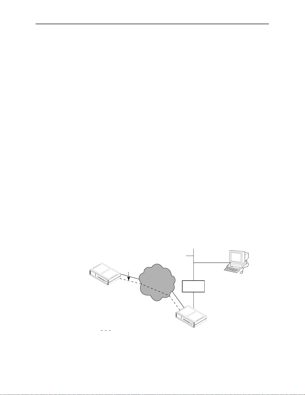
IMC Connection – Same Subnet
In this example, DSU A is connected to:
The NMS, at the central site, via a LAN adapter
A remote unit, DSU B, through the proprietary IMC
NOTE:
Interconnected DSUs will automatically pass routing information between
each other using a proprietary protocol. However, a static route to
subnet 135.18.2.0 must be set in the routing table of the NMS Host.
Remote
Site
DSU B
IMC Interface
135.18.2.2
Subnet 135.18.2.0
IMC
Network
IMC Interface
135.18.2.1
Ethernet
Adapter
NMS Host
135.18.40.1
LAN
Subnet 135.18.40.0
Management Port
135.18.40.3
Central
Site
5-2
Path of Management Data
November 1997
DSU A
496-15087
7610-A2-GB20-10
Page 36
Using Routers to Route DSU Management Data
6
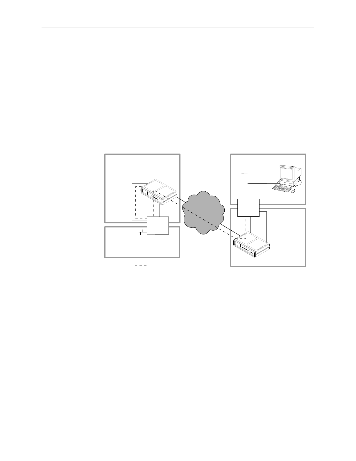
In this example, the DSUs:
Receive their management data through the Management port connection to
the AUX port of the router.
Do not route the data among themselves. Routers route management data
for the connected DSUs using the management data path between the
routers.
The illustration shows each DSU with its own subnet. This subnet is independent
of the subnet on the LAN, which is supported by the local router. This enables the
router to distinguish the data destined for the DSU from the data for the LAN.
IP Addressing
Subnet 135.18.5.0
Management
135.18.5.2
AUX Port
135.18.5.1
135.18.2.1
Subnet 135.18.2.0
Port
DTE
Port
Router
To LAN
Path of Management Data
DDS
Network
Subnet 135.18.1.0
NMS
Host
135.18.1.2
135.18.1.1
Router
Subnet 135.18.4.0
DTE
Port
AUX Port
135.18.4.1
Management
135.18.4.2
Port
496-1508
7610-A2-GB20-10
November 1997
5-3
Page 37

IP Addressing
Assigning IP Addresses and Subnet Masks
Once you select an IP scheme, assign an address(es) to the DSU.
If using . . .
The Management port as a management
interface
An external modem connected to the
Management port, and you want to
configure an alternate IP address and
subnet mask for dialing out traps using the
alternate alarm directory
The IMC Assign the IP address and subnet mask.
The SNMP NMS Security Options screen provides options to perform security
checking on the IP address of the SNMP management system attempting to
communicate to the DSU. Refer to SNMP NMS Security Options, Table A-11.
Choosing a Default Network Destination
You can route an SNMP or Telnet session to a default network destination. To
configure a Default Network Destination, follow this menu selection sequence:
Then . . .
Assign the Management port IP address
and subnet mask. Refer to Communication
Protocol Options, Table A-9.
Enter the alternate Management port IP
address and subnet mask. Refer to
Communication Protocol Options,
Table A-9.
Refer to Network Interface Options,
Table A-2.
Main Menu→Configuration→Load Configuration From →Edit→
→
SNMP & Communication
Communication Protocol
Refer to Communication Protocol Options, Table A-9.
5-4
November 1997
7610-A2-GB20-10
Page 38

Monitoring the DSU
What to Monitor
This chapter presents information on how to access and monitor DSU status and
performance statistics on the DDS network. You can monitor DSU operations by
viewing:
LEDs on the ATI Status screen or the DSU’s front panel
Unit Status screen on the ATI
6
DSU LEDs
Highest priority Health and Status message displays on the right on the last
line of all screens.
Network Interface Status screen on the ATI
Network Performance Statistics screen on the ATI
NMS via SNMP MIB objects
Refer to
DSU.
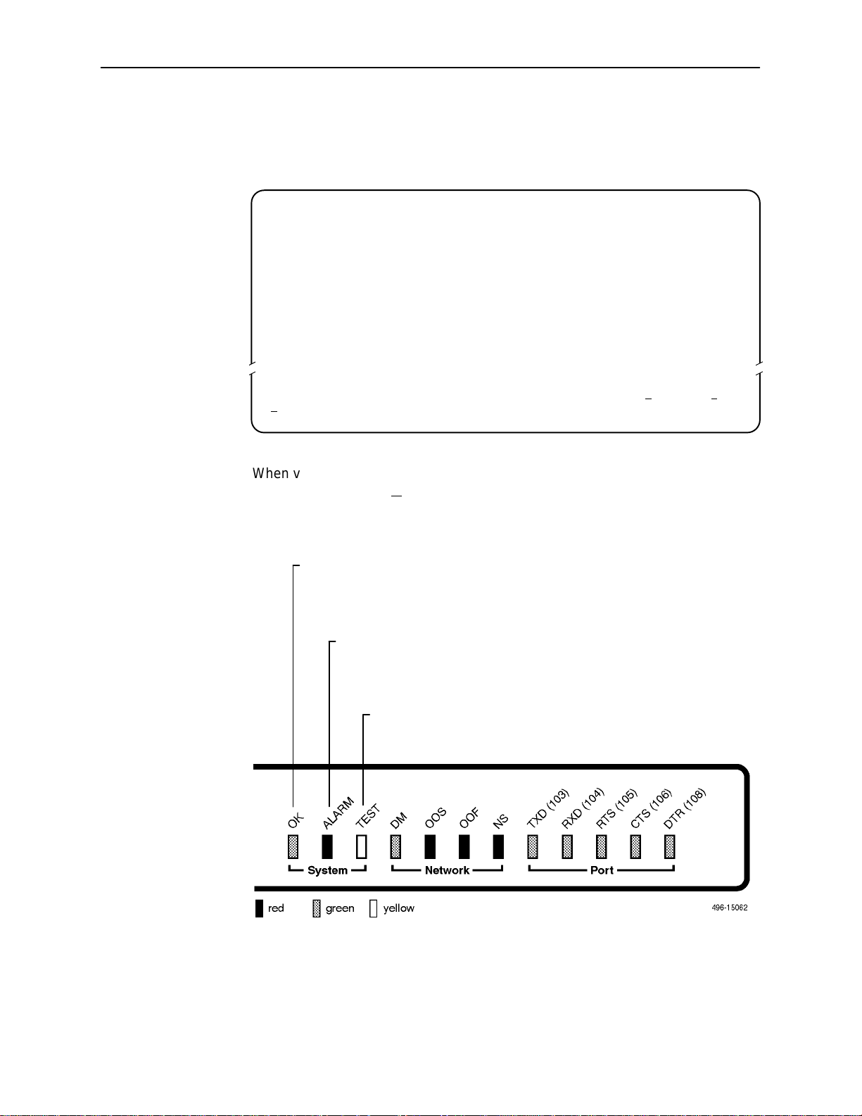
The DSU LEDs can be viewed on the Display LEDs Status screen. This ATI
status screen is available locally and remotely.
The 12 LEDs are organized in three groups:
System LEDs display the status of the unit
Network LEDs provide the status of the network interface
Port LEDs display the activity on the user data (DTE) port
MIB Descriptions
, Appendix C, for the SNMP MIBs supported by the
7610-A2-GB20-10
November 1997
6-1
Page 39
Monitoring the DSU
To view the LED status screen, follow this menu selection sequence:
Main Menu→Status→Display LEDs
main/status/leds
Device Name: Model: 7610
DISPLAY LEDS
SYSTEM NETWORK DTE
System LEDs
OK ALARM TEST DM OOS OOF NS TXD RXD RTS CTS DTR
blinking blinking
––––––––––––––––––––––––––––––––––––––––––––––––––––––––––––––––––––––––––––––––
efresh
R
ESC for previous menu M
| |
ainMenu Exit
When viewed via the ATI, the status display screen is updated approximately
every 5 seconds. Use R
OK:
ON – DSU is operational.
OFF – DSU is performing a power-up self-test, has detected a system
failure, or there is no power.
ALARM:
ON – DSU has detected an alarm condition locally or from
efresh to obtain a current status of all LEDs.
the network. Refer to the
Troubleshooting
Chapter 8.
TEST:
ON – Test in progress. Test can be initiated locally, remotely,
or from the network. Includes power-up self-test.
section in
6-2
November 1997
7610-A2-GB20-10
Page 40
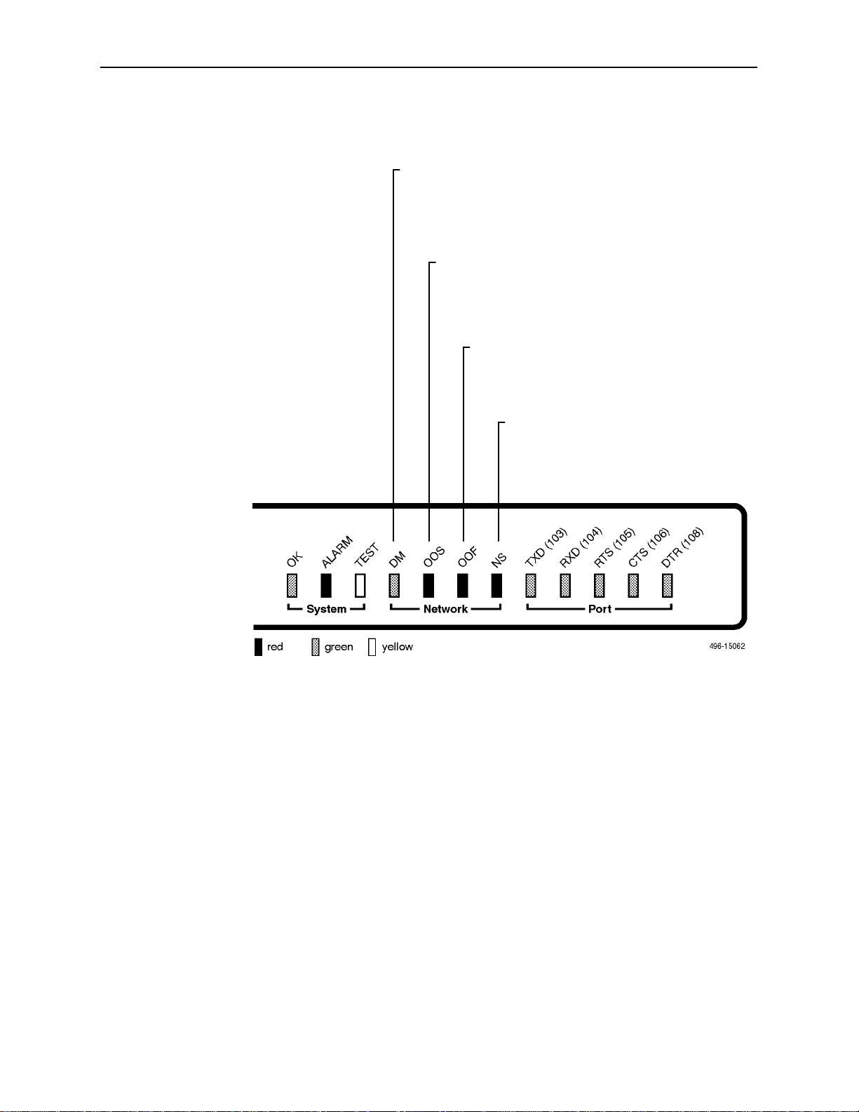
Network LEDs
Monitoring the DSU
DM – Data Mode:
ON – DSU (DDS network interface) is sending or
receiving data, or is in DMI condition
(all 1’s being received).
OFF – DDS network interface is receiving CMI codes.
OOS – Out of Service:
ON – The network has notified the DSU that
the remote unit is out of service.
Refer to Health and Status Messages,
Table 6-1.
OOF – Out of Frame:
ON – DSU is detecting an out of frame
condition. Refer to Health and Status
Messages, Table 6-1.
NS – No Signal:
ON – DDS network interface detects
no signal. Refer to Health and
Status Messages, Table 6-1.
7610-A2-GB20-10
November 1997
6-3
Page 41
Monitoring the DSU
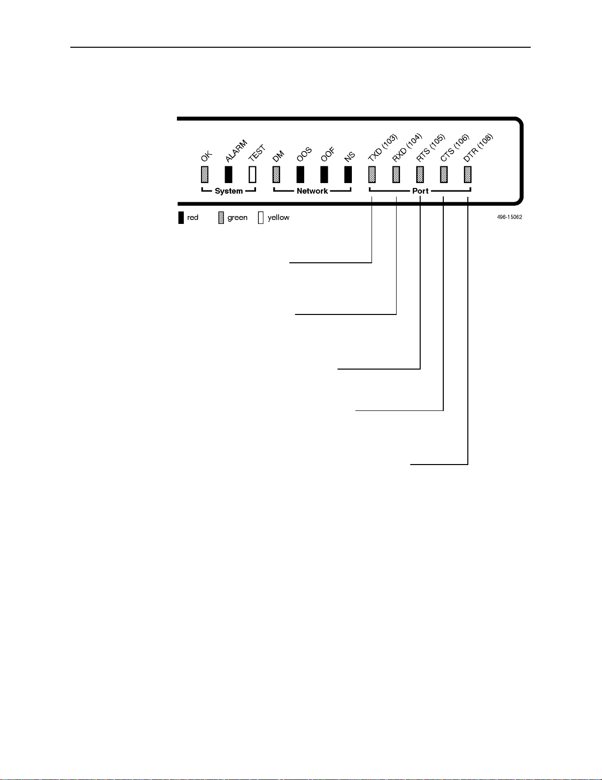
Port LEDs
TXD – Transmitted Data:
ON – Receiving all 0s from the DTE.
OFF – Receiving all 1s from the DTE.
Blinking – User data is being transferred.
RXD – Received Data:
ON – Sending all 0s to the DTE.
OFF – Sending all 1s to the DTE.
Blinking – User data is being transferred.
RTS – Request to Send:
ON – DTE is activating a control signal to
indicate readiness to transmit data.
CTS – Clear to Send:
ON – DSU is activating a control signal to
indicate to the DTE that it can start
sending data.
DTR – Data Terminal Ready:
ON – DTE is activating a control signal to
indicate readiness for operation.
6-4
November 1997
7610-A2-GB20-10
Page 42

Unit Status
Status is a branch of the ATI main menu. From Status, the System and Test
Status screen is available and has three sections:
Health and Status – Displays messages in priority order (highest to lowest).
Refer to Health and Status Messages, Table 6-1.
Self-Test Results – Results of the Diagnostic test run on the device itself.
Refer to Self-Test Results Messages, Table 6-2.
Test Status – Currently active tests. Refer to Test Status Messages,
Table 7-1.
Viewing Health and Status
To view Health and Status information, follow this menu selection sequence:
Main Menu→Status→System and Test Status
The following messages appear in the first column of the System and Test Status
screen. The highest priority Health and Status message also appears on all ATI
screens on the bottom right. The messages are listed from high to low priority in
Table 6-1.
Monitoring the DSU
Table 6-1. Health and Status Messages (1 of 2)
Message
Cross Pair
Detection
No Signal
hhh:mm:ss
Out of Service
hhh:mm:ss
1
hhh:mm:ss
and seconds. When the maximum time has been exceeded, 255:59:59+ appears.
1
1
What Message Indicates What To Do
The DDS Receive (RX) and
Transmit (TX) pairs are
crossed on the network
interface. Alarm LED is on.
No signal is being received.
Local DSU network problem.
The Alarm and NS LEDs are
on and Network Performance
Statistics are active.
DSU is receiving out of
service code from the
network for the remote unit.
The Alarm and OOS LEDs
are on and Network
Performance Statistics are
active.
indicates the amount of time the condition has existed in hours, minutes,
Reverse the RX and TX pair at the
punchdown block or other
termination point.
1. Verify that the network cable is
securely attached at both ends.
2. Contact network provider.
1. Verify that the remote site is in
service.
2. Contact network provider.
7610-A2-GB20-10
November 1997
6-5
Page 43

Monitoring the DSU
Table 6-1. Health and Status Messages (2 of 2)
Message What To DoWhat Message Indicates
Out of Frame
hhh:mm:ss
Excessive BPVs
hhh:mm:ss
In-Band Fram Err
hhh:mm:ss
1
1
1
User Data Port
DTR Off
DSU is detecting an out of
frame condition, associated
with:
Receiving out of frame
code from the network.
DSU detecting out of frame
errors with 64 kbps CC
data rate.
DSU unable to synchronize
local receiver circuit with
line signal.
Data rates do not match or
network trouble causing
bipolar violations. Alarm LED
is on and Network
Performance Statistics are
active.
The IMC communication
between the local and remote
DSU is not working.
The DTE is not ready to
transmit or receive data. This
message will not appear
unless Monitor DTR is
enabled.
1. Verify that the line rate matches
the configured rate.
2. Contact network provider.
1. Verify that the network cable is
securely attached at both ends.
2. Contact network provider if
problem persists.
1. Verify that the remote unit has
IMC set at the same rate.
2. Contact network provider if
problem persists.
Check on the DTE status. Verify
that the DTE is powered up and
asserting DTR.
Net Mgmt Link
Down
Communications between the
DSU and an NMS are not
possible and the:
Management Port Use is
1. Check the devices in the
management path data and the
status of the NMS.
2. Try to access the unit remotely.
set to Net Link and/or
IMC is enabled.
Device Fail
yyyyyyyy
DSU Operational DSU is functioning properly
An internal error has been
detected by the operating
software.
yyyyyyyy
indicates
the 8-digit hexadecimal failure
code.
1. Provide the 8-digit failure code
shown (
yyyyyyyy
) to your service
representative.
2. Reset the DSU to clear the
condition and message.
No action needed.
and there are no status
messages to display.
1
hhh:mm:ss
indicates the amount of time the condition has existed in hours, minutes,
and seconds. When the maximum time has been exceeded, 255:59:59+ appears.
6-6
November 1997
7610-A2-GB20-10
Page 44

Self-Test Results
representative for assistance if
Monitoring the DSU
The results of the last power-up or reset self-test appear in the middle column of
the System and Test Status screen.
Table 6-2. Self-Test Results Messages
Message
Device Fail One or more of the DSU’s integrated
Memory Fail DSU failed memory verification.
Passed The DSU has been plugged in or
Network Interface Status
The network interface status fields are read-only:
Line Rate (Kbps). If the DSU is connected to an operating line and the Line
Rate (Kbps) shows Autobaud and does not change to a line rate within about
25 seconds, Line Rate (Kbps) may have to be reconfigured manually. Refer
to System Options, Table A-1.
Loop Loss (dB). The loop loss is the loss of signal strength of the receive line
signal from the local loop.
What Message Indicates What To Do
1. Reset the DSU and try again.
circuit chips has failed device-level
testing.
reset and has passed the diagnostic
test. There are no other status
messages.
2. Call your service
representative for assistance if
the message reappears.
No action needed.
To view the Network Interface Status, follow this menu selection sequence:
Main Menu→Status→Network Interface Status
Table 6-3. Network Interface Status Screen Contents
Field
Line Rate (Kbps) 56 Kbps
Loop Loss (dB)
Status What the Status Indicates
Line rate on the network interface.
64 CC
64 LADS
Autobaud
No Signal No signal can be detected over the
0 to –65 dB Amount of loop loss – loss of signal
Inoperative The line may be disconnected.
Autobaud indicates the DSU is
trying to determine the network line
rate. This should be a temporary
condition.
network interface.
strength of the receive line signal
from the local loop, measured in
decibels.
7610-A2-GB20-10
November 1997
6-7
Page 45

Monitoring the DSU
Network Performance Statistics
Performance statistics for the network interface are available to:
Monitor the current status of the network operations.
View the DSU’s performance statistics, which:
— Assist you in determining the duration of specific conditions.
— Provide a historical context for problem detection and analysis.
To view the Network Performance Statistics, follow this menu selection sequence:
Main Menu→Status→Performance Statistics
main/status/performance
Device Name: Model: 7610
NETWORK PERFORMANCE STATISTICS
No Signal Count: 101920 26:33:08
Out of Service Count: 0 0:00:00
Out of Frame Count: 621 8:53:49
Excessive BPV Count: 99830 144:28:11
Invalid BPV Count: 87409
––––––––––––––––––––––––––––––––––––––––––––––––––––––––––––––––––––––––––––––––
efresh ClrStats
R
ESC for previous menu M
ainMenu Exit
All counts show the number of occurrences since the last reset of the counters.
Invalid BPV is a raw count of the number of invalid Bipolar Violations. In the last
column,
hhh:mm:ss
indicates the amount of time the condition has existed in
hours, minutes, and seconds. When the maximum time has been exceeded,
255:59:59+ appears.
The screen appears with the cursor in the function area below the dotted line. To
update the performance statistics, select R
Select C
lrStats is not available for an Access level of 3.
C
lrStats and press Return to clear all statistics and refresh the screen.
efresh and press Return.
6-8
November 1997
7610-A2-GB20-10
Page 46

Testing
Detecting Problems
The DSU can detect and report problem conditions and perform diagnostic tests.
The DSU offers a number of indicators to alert you to possible problems:
7
LEDs – Refer to the
SNMP Traps – For information on traps, refer to the
section in Chapter 8.
Health and status messages and network performance statistics. Refer to
Monitoring the DSU
Alarm Condition Indications.
The following table shows the available indicators of alarm conditions on the
network interface and the User Data port.
Alarm Condition
Crossed Pairs Y
No Signal (NS) Y
Out of Service (OOS) Y
Out of Frame (OOF) Y
Excessive Bipolar
Violations (BPV)
Inband Framing Error N Y Y Y N
DTR Off Y
1
Link Up/Link Down Trap
DSU LEDs
, Chapter 6.
SNMP
Trap
1
1
1
1
1
Y
1
section in Chapter 6.
Configuring SNMP Traps
A TI Status
Screen
Y Y Y N
Y Y Y Y
Y Y Y Y
Y Y Y Y
Y Y Y N
Y N N Y
ASCII Alarm
(if configured)
Alarm
LED
Specific
LED
7610-A2-GB20-10
To configure ASCII Alarms, use the Alarms & Traps options screen. Refer to
Alarms & Traps Options, Table A-8. For additional information regarding ASCII
alarm generation, refer to the
November 1997
Alarm Messages
section of Chapter 8.
7-1
Page 47
Testing
Tests Available
Network Tests
From the Test menu, you can run network tests, data port tests, and a lamp test
for the front panel LEDs. Loopbacks can be initiated locally and remotely. Refer to
Loopbacks, Table 7-2.
The Test menu is limited to users with an access level of 1 or 2. To access the
Test menu, follow this menu selection sequence:
Main Menu→Test
Network tests require the participation of your network service provider.
The DSU supports physical-level tests independently on a per-interface basis.
The CSU and DSU loopbacks and 511 test pattern send/monitor are
supported on the network interface.
The Local Loopback and 511 test pattern send/monitor are supported on the
DTE port.
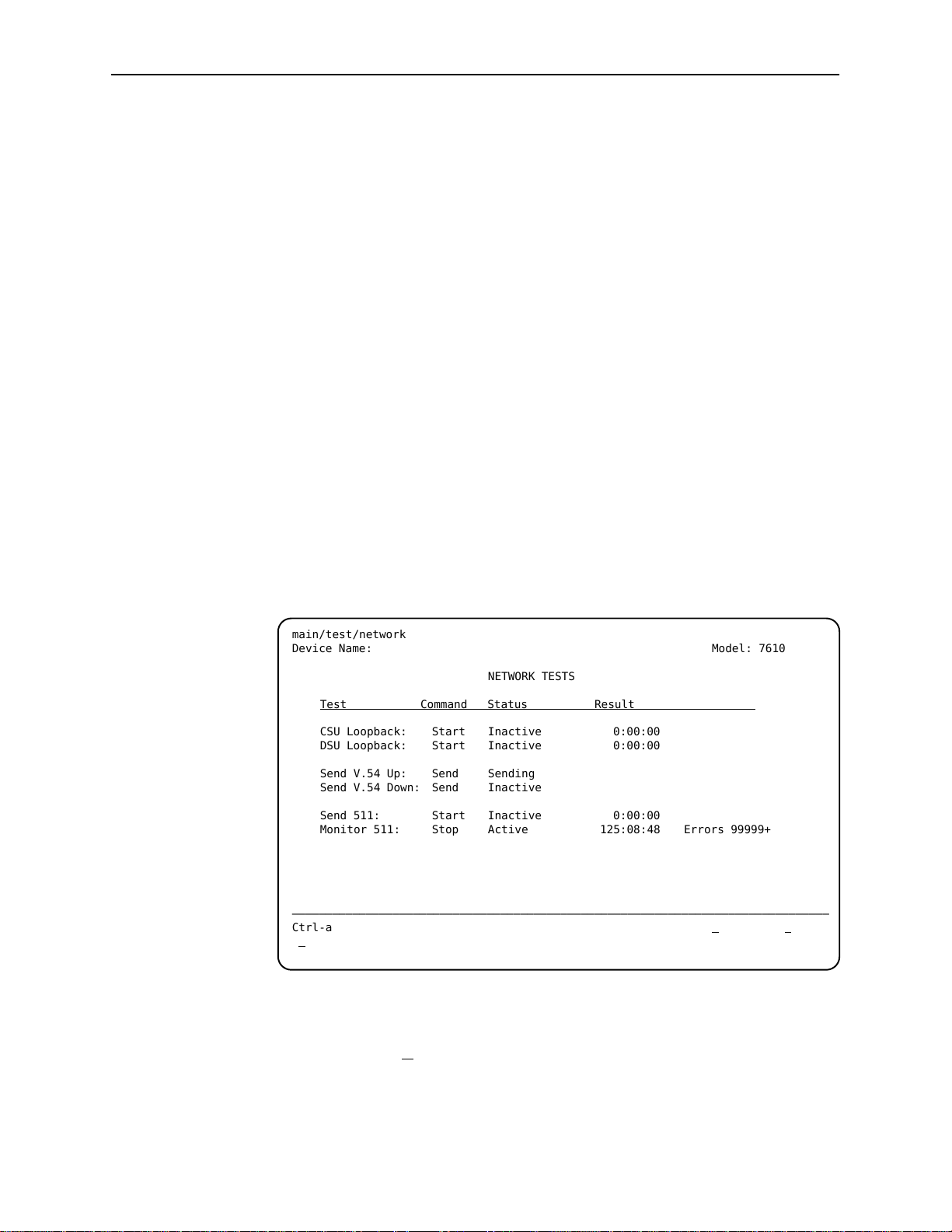
To access the Network Tests screen, follow this menu selection sequence:
Main Menu→Test→Network Tests
main/test/network
Device Name: Model: 7610
NETWORK TESTS
Test Command Status Result
CSU Loopback: Start Inactive 0:00:00
DSU Loopback: Start Inactive 0:00:00
Send V.54 Up: Send Sending
Send V.54 Down: Send Inactive
Send 511: Start Inactive 0:00:00
Monitor 511: Stop Active 125:08:48 Errors 99999+
––––––––––––––––––––––––––––––––––––––––––––––––––––––––––––––––––––––––––––––––
Ctrl-a to access these functions, ESC for previous menu M
R
esetMon
ainMenu Exit
7-2
Use the Command column to start or stop a test by pressing Enter. The Result
column displays the test duration since the last device reset. When the Monitor
511 test is active, R
esetMon is available to reset the error counter to zero.
Selecting the Stop command on the Network Test screen or Abort All Tests from
the Test menu will not disrupt a network-initiated loopback.
November 1997
7610-A2-GB20-10
Page 48
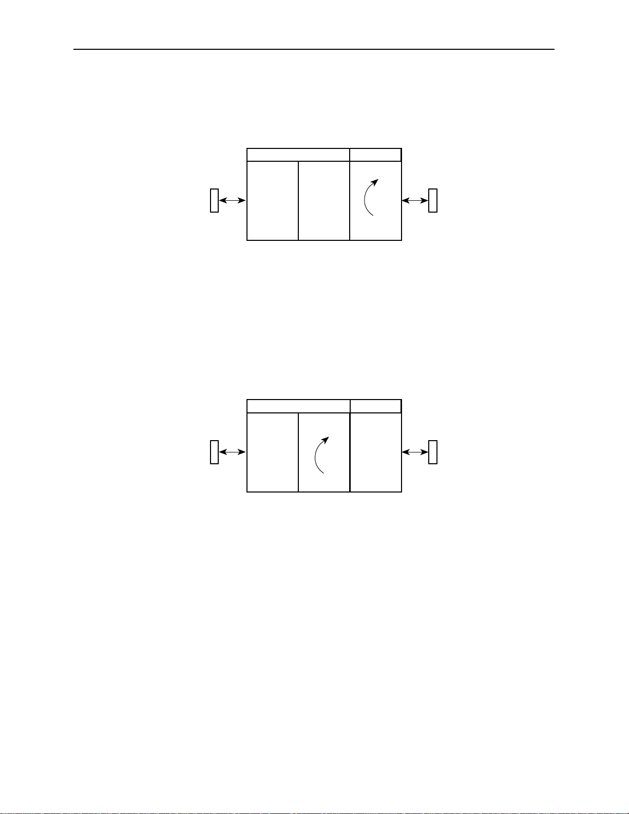
CSU or External Network Loopback
CSU loopback is an external loopback that is located as close as possible to the
network interface. An active CSU loopback disrupts IP data going over the IMC.
Testing
DSU CSU
DTE
Port
Interface
DSU or Internal Network Loopback
DSU loopback is an internal loopback that is located as close as possible to the
customer interface serving the DTE.
An active DSU loopback initiated from the network disrupts IP data going over the
IMC. However, this test is not disruptive when initiated by the user (via ATI) or by
the NMS.
DTE
Port
Interface
DTE
DTE
Aggregate
CSU Loopback
DSU CSU
Aggregate
DDS
Network
Port
496-15144
DDS
Network
Port
Send V.54 Up/Down Sequences
The local DSU can send an ITU-T V.54 Up or Down sequence to request the
activation or termination of a DSU (digital) loopback of a remote unit. This is the
same as the DSU Loopback shown above except the test is activated remotely.
The DSU can send:
In-band V.54 Up (activation) code to request a Remote DSU Loopback
(V.54 Loop 2) at the remote DSU or
In-band V.54 Down (deactivation) code to request the termination of a
Remote DSU Loopback (V.54 Loop 2) at the remote DSU
Refer to the
Select Send. Sending appears in the Status column followed (after 3 seconds) by
Command Complete at the bottom of the screen.
7610-A2-GB20-10
DSU Loopback
Network Tests
November 1997
496-15160
section for an example of the Network Tests screen.
7-3
Page 49
Testing
511 Test Pattern for the Network
This test sends or monitors the 511 test pattern over the network interface.
The Monitor 511 test also provides an error counter that can be reset. Refer to
Network Tests
the
Data Port Tests
section for an example of the Network Tests screen.
Local Loopback
For an example of the fields on a test menu screen, refer to the
section. To access the Data Port Tests screen, follow this menu selection
sequence:
Network Tests
Main Menu→Test→Data Port Tests
Local Loopback loops the user data back to the DTE. This loopback is located as
close as possible to the User Data Port (DTE) interface.
DSU CSU
DTE
Port
DTE
Interface
Aggregate
Local Loopback
DDS
Network
Port
496-15145
511 Test Pattern for the DTE
This test sends or monitors a 511 test pattern over the User Data Port interface.
The 511 monitor expects the external equipment to provide the clock for the
511 pattern on the interchange circuit CT113 – Transmit Signal Element Timing –
DTE Source (XTXC or TT) for timing the incoming pattern. Refer to the
V.35 User Data Port Connector
Lamp Test
The DSU supports a Lamp test from the Test menu to determine whether all
LEDs are lighting and functioning properly.
During the Lamp test, all LEDs blink simultaneously every second. When you
stop the Lamp test, the LEDs are restored to their normal condition.
7-4
section of Appendix E.
November 1997
7610-A2-GB20-10
Page 50

Ending an Active Test
A test initiated by the user can be ended by the user.
A Test Timeout option is available to automatically terminate a user-initiated
Loopback or Pattern test (as opposed to manually terminating a test) after it
has been running a specified period of time. Refer to System Options,
Table A-1.
Test Timeout does not pertain to tests commanded by the:
— Network, such as the network-initiated CSU and DSU Loopbacks.
— DTE, such as the DTE-initiated Local Loopback.
On each test screen is a command column. Pressing Return when the cursor
is on the Start command stops the test.
Use the Abort All Tests selection from the Test menu to stop all tests running
on all interfaces, with the exception of network or DTE-initiated loopbacks.
Command Complete appears when all tests on all interfaces have been
terminated.
Testing
Test Status Messages
The Test Status Messages in Table 7-1 appear in the right-most column of the
System and Test Status screen. For additional information on loopbacks, refer to
Loopbacks, Table 7-2.
Table 7-1. Test Status Messages (1 of 2)
Test Status Message
CSU Loopback Active A CSU Loopback toward the network is currently active. Only
DSU Loopback Active A DSU Loopback toward the network is currently active. Only
Lamp Test Active The Lamp T est is active, causing the LEDs on the front panel to
Local Loopback Active A local loopback toward the DTE is currently active.
Monitoring 51 1 on
Network
Monitoring 511 on Port DSU is monitoring a 511 test pattern over the DTE port.
Network-init. CSU LB
Active
Meaning
applies to a test initiated by the user via the A TI or the NMS.
applies to a test initiated by the user via the A TI or the NMS.
light.
DSU is monitoring a 51 1 test pattern on the network interface.
A CSU Loopback initiated by the network is currently active.
7610-A2-GB20-10
November 1997
7-5
Page 51

Testing
Table 7-1. Test Status Messages (2 of 2)
Test Status Message Meaning
Loopbacks
Network-init. DSU LB
Active
No Test Active Status message, indicating no local, remote, or network test in
Sending 51 1 on
Network
Sending 511 on Port A 511 test pattern is being sent over the DTE port.
V.54-initiated DSU LB
Active
A DSU Loopback initiated by the network is currently active.
If the network service is 56 kbps, the network loopback is
non-latching. A non-latching loopback ends when the
network activation codes stop.
If the network service is 64 kbps CC, the network loopback
is latching. This condition can only occur when the Network
Interface option Network-initiated DSU Loopback (64K CC)
is enabled. Refer to Network Interface Options, Table A-2.
progress.
A 51 1 test pattern is being sent over the network interface.
A DSU loopback is active that was initiated by the detection of
a V.54 sequence originated by the remote unit. This condition
can only occur when V.54 Initiated DSU Loopback is enabled.
Refer to Network Interface Options, Table A-2.
Loopbacks can be started from a variety of points in the network. Refer to
Table 7-2 for further information.
Table 7-2. Loopbacks (1 of 2)
Loopback T ype
Bilateral Loopback ATI
CSU Loopback ATI (Network tests)
DSU Loopback
(Digital)
Local Loopback ATI
Initiated By Notes
NMS
Remote unit sending
V.54 sequence
NMS
DDS Network, by
loop current reversal
ATI
NMS
DTE via CT141
NMS
When enabled, running a DSU loopback
also automatically starts a local
loopback. Refer to Data Port Options,
Table A-3, to enable.
When initiated by the network, CSU
Loopback cannot be disabled by the
user. When IMC is enabled, the
aggregate data is looped back to the
network.
When IMC is enabled, only user data is
looped back to the network. Refer to
Data Port Options, Table A-3.
Control via CT141 can be disabled.
Refer to Data Port Options, Table A-3.
7-6
November 1997
7610-A2-GB20-10
Page 52

Table 7-2. Loopbacks (2 of 2)
Loopback T ype NotesInitiated By
Testing
Device Reset
Network-initiated
56 kbps DSU
Loopback (Nonlatching loopback)
Network-initiated
64 kbps CC DSU
Loopback
(Latching loopback)
Remote Digital
Loopback
V.54 Sequences to
remote unit
DDS Network When IMC is enabled, the aggregate
data stream is looped back to the
network. Cannot be disabled by user.
DDS Network Includes optional data scrambling and
uses 25-second timer to detect the
network sequence. When IMC is
enabled, the aggregate data stream is
looped back to the network. Can be
disabled by user.
Remote unit sending
V.54 sequence
ATI
NMS
DTE via CT140
Same as a DSU Loopback but initiated
by a remote unit via V.54 sequence.
When IMC is enabled, only user data is
looped back to the network. Can be
disabled locally. Refer to Network
Interface Options, Table A-2.
Control via CT140 can be disabled.
Refer to Data Port Options, Table A-3.
The DSU can be reset locally or remotely. From the Control menu, select Reset
Device and press Return. The DSU reinitializes itself, performing a Device
Self-Test. Refer to Self-Test Results Messages, Table 6-2.
Misconfiguring the DSU could make the user interface inaccessible, leaving it in a
state where an ATI session cannot be started through the Terminal port or via a
Telnet session. If this occurs, DSU connectivity can be restored with a terminal
that is directly connected and set for Terminal Port option defaults.
Two methods can be used to restore access to the ATI. Both methods cause a
device reset.
Reset Terminal Port – Allows you to only reset the configuration options
related to Terminal port usage. No security-related configuration options are
changed.
Reload Factory Defaults – Allows you to reload the Default Factory
Configurations, resetting all of the configuration areas and control settings for
security reasons. This method is useful when the user’s passwords have
been forgotten.
7610-A2-GB20-10
November 1997
7-7
Page 53

Testing
Refer to Terminal Port Options, Table A-4. To reset Terminal port settings:
Procedure
1. At the async terminal connected to the Terminal port, verify that the Terminal
port options are set to the default settings:
— Data Rate(Kbps) to 9.6
— Character Length to 8
— Stop Bits to 1
— Parity to None
2. Power the DSU Off and back On. The DSU performs a power-up routine.
3. Immediately after the OK LED turns on, press the Return key 5 times quickly
in succession. The System Paused screen appears.
4. Tab to the desired method, and enter yes (or y) for the selected prompt.
If entering yes to prompt . . .
Reset Terminal Port Options Terminal port options are set to their factory
Reload Factory Defaults Factory default settings contained in the Default
Then all . . .
default values. Refer to Terminal Port Options,
Table A-4.
Factory Configuration area are loaded in Current,
Customer 1, and Customer 2 configuration areas.
Any changes to configuration and control settings
will be replaced by the factory defaults.
If no (or n) is entered, or if no selection is made within 30 seconds, the DSU
returns to the condition or operation it was in when the system pause was
initiated, with the Terminal port data rate returning to its configured rate.
5. If yes (or y) is entered, the DSU resets itself and initiates a Device Self-Test.
Connectivity is restored and the Main Menu screen appears.
7-8
November 1997
7610-A2-GB20-10
Page 54

Messages and Troubleshooting
Messages and Troubleshooting
There are many messages available to assess the status of the device and
contribute to problem resolutions. Refer to the following sections:
Alarm Messages
—
ASCII Alarms
—
ASCII Alarm Messages
8
Alarm Messages
ASCII Alarms
—
Configuring SNMP Traps
—
Dialing Out SNMP Traps
Device Messages
T roubleshooting
Alarm messages and SNMP traps are unsolicited messages sent out from the
DSU automatically when the DSU detects conditions set by the user.
Alarm messages are sent out to an ASCII terminal or printer via the Management
port if:
Port Use is configured for Alarms. Refer to Management Port Options,
Table A-5.
Each ASCII Alarm Message to be generated has been enabled. Refer to
Network Interface Options, Table A-2, and System Options, Table A-1.
ASCII Alarm Messages option is enabled. Refer to Alarms & Traps Options,
Table A-8.
7610-A2-GB20-10
November 1997
8-1
Page 55

Messages and Troubleshooting
When individually enabled, a specific alarm is sent at the start of the
corresponding alarm condition. If more than one alarm condition exists, only the
highest priority alarm will be sent. Any other alarms are sent out when the higher
priority alarm clears. An alarm cleared message is sent when the alarm
conditions no longer exist.
The dialing out of ASCII Alarm messages, via an external device (e.g. modem)
connected to the Management port, can only occur when, in addition to the
above, the:
External Device Commands is set to AT or Other. Refer to External Device
Options, Table A-6.
Alarm and Trap Dial-Out is enabled. Refer to Alarms & Traps Options,
Table A-8.
ASCII Alarm Messages
Refer to the
device name information. Each ASCII alarm message is preceded by the device
name and a time stamp. The time stamp
number of days, hours, and minutes since the DSU’s last reset. The time resets
to zero on power up or reset. An ASCII alarm message displays similar to this
example:
NE815378 283:14:57 Crossed Pair condition has been detected
The following messages can be generated by the DSU and are listed in high to
low priority order:
A Crossed Pair condition has been detected on the DDS Network Interface.
A No Signal (NS) condition has been detected on the DDS Network Interface.
An Out of Service (OOS) condition has been detected on the DDS Network
Interface.
An Out of Frame (OOF) condition has been detected on the DDS Network
Interface.
An Excessive Bipolar Violations (BPV) condition has been detected on the
DDS Network Interface.
An In-Band Framing Error condition has been detected on the DDS Network
Interface.
Entering Device and System Information
(ddd:hh:mm)
on the DDS Network Interface
section of Chapter 3 for
represents the cumulative
8-2
November 1997
7610-A2-GB20-10
Page 56

Configuring SNMP Traps
An SNMP trap can be automatically sent out the IMC or the Management port to
the SNMP manager when the DSU detects conditions set by the user. These
traps enable the SNMP manager to gauge the state of the network. Refer to
Standards Compliance for SNMP Traps,
supported by the DSU.
To configure the DSU for SNMP traps, use the SNMP Traps Options screen to:
H Enable SNMP traps.
H Set the number of SNMP managers that receive SNMP traps from the DSU.
H Enter an IP address and network destination for each SNMP manager
H Select the type of SNMP traps to be sent from the DSU.
To configure SNMP Traps, follow this menu selection sequence:
Messages and Troubleshooting
Appendix D, for details of SNMP traps
specified.
Refer to SNMP Traps Options, Table A-12.
Dialing Out SNMP Traps
Configure the SNMP traps before performing this procedure.
" Procedure
1. Configure the phone directories to use when dialing out SNMP traps through
2. Use the Alarms & Traps Options to enable the DSU’s automatic call initiation
Refer to Alarms & Traps Options, Table A-8.
Main Menu→Configuration→Load Configuration From→Edit
→
SNMP & Communication→SNMP Traps
the Management port and a connected external device. Refer to the
section in Chapter 3.
Setup
to a remote device with Alarm & Trap Dial-Out, Call Retry, and Alternate
Dial-Out Directory. Follow this menu selection sequence:
Main Menu→Configuration→Load Configuration From→Edit
Call
→
Alarms & Traps
7610-A2-GB20-10
November 1997
8-3
Page 57

Messages and Troubleshooting
Device Messages
The Device Messages in Table 8-1, listed in alphabetical order, may appear in the
messages area at the bottom of the ATI screens.
Table 8-1. Device Messages (1 of 2)
Device Message
Blank Entries
Removed
Command Complete Action requested has
Invalid Character (x)1A nonprintable ASCII
Invalid – Network
Initiated CSU (or DSU)
Loopback Active
Invalid Password Login is required and an
Invalid – [Test]
Already Active
What Message Indicates What To Do
New had been selected
from the Administer Logins
screen, no entry was made,
and Save was selected.
successfully completed.
character has been
entered.
Network-initiated loopback
was in progress when
another selection was
made.
incorrect password was
entered; access is denied.
[Test] can be a CSU, DSU,
or DTE Local Loopback, or
a Send 51 1 or Monitor 511.
The [test] was already in
progress when another
selection was made.
No action needed.
Reenter the Login ID,
Password, and Access Level.
No action needed.
Reenter information using valid
characters.
No action needed.
Try again.
Contact your system
administrator to verify your
password.
Allow test to continue.
Select another test.
Stop the test.
8-4
Invalid Test
Combination
Limit of six Login IDs
reached
No Security Records
to Delete
1
x
is the character not being accepted.
A loopback or 51 1 pattern
test was in progress when
Start was selected to start
another test, or was active
on the same or another
interface when Start was
selected.
An attempt to enter a new
login ID was made, and the
limit of six login/password
combinations has been
reached.
Delete was selected from
the Administer Login
screen, and no security
records had been defined.
November 1997
Wait until other test ends and
message clears.
Abort all tests from the Test
menu screen.
Stop the test from the same
screen the test was started
from.
1. Delete another login/password
combination.
2. Reenter the new login ID.
No action needed.
Enter a security record.
7610-A2-GB20-10
Page 58

Table 8-1. Device Messages (2 of 2)
Device Message What T o DoWhat Message Indicates
Messages and Troubleshooting
Troubleshooting
Password Matching
Error – Re-enter
Password
Please Wait Command takes longer
Test Active A test is running and no
Password entered in the
Re-enter Password field of
the Administer Logins
screen does not match
what was entered in the
Password field.
than 5 seconds.
higher priority health and
status messages exist.
Try again.
Contact your system
administrator to verify your
password.
Wait until message clears.
Contact service provider if test
initiated by the network.
Wait until the other test ends
and message clears.
Cancel all tests from the Test
screen.
Stop the test from the same
screen the test was started
from.
This DSU is designed to provide you with many years of trouble-free service. If a
problem occurs, however, refer to Table 8-2 for possible solutions.
Table 8-2. Troubleshooting (1 of 2)
Symptom
Alarm LED is on. One of several alarm
Cannot access the
DSU via the ATI.
Device Fail appears
on the System and
Test Status screen
under Self-Test
results.
Possible Cause Solutions
conditions exists. Health
and Status displays the
alarm condition.
Login or password is
incorrect, Terminal port is
misconfigured, or the DSU
otherwise configured so it
prevents access.
The DSU detects an
internal hardware failure.
Refer to Health and Status
Messages, Table 6-1, for
recommended action.
1. Power the DSU on and off and
try again.
2. If problem recurs, try to access
the A TI through a Telnet session,
if enabled.
3. Do a Device Reset. Refer to the
Device Reset
Chapter 7.
Power the DSU off and on and
try again.
Contact your service
representative.
section of
7610-A2-GB20-10
November 1997
8-5
Page 59

Messages and Troubleshooting
4. If getting excessive Loop Loss
Table 8-2. Troubleshooting (2 of 2)
Symptom SolutionsPossible Cause
An LED is not lit. LED is burned out. Run the Lamp test. If the LED in
question does not flash with the
other LEDs, then contact your
service representative.
No power, or the
LEDs are not lit.
Not receiving data;
DSU is not
responding.
The power cord is not
securely plugged into the
wall receptacle and into the
rear panel connection.
The wall receptacle has no
power.
DDS line rate/speed has
changed.
Excessive BPVs causing
DSU to become stuck in
Autobaud mode.
Excessive Loop Loss
causing DSU to become
stuck in Autobaud mode.
Check that the power cord is
securely attached at both ends.
Check the wall receptacle power
by plugging in some equipment
that is known to be working.
Check the circuit breaker.
Verify that your site is not on an
energy management program.
1. Verify that your subscriber loop is
running at 56 or 64 CC kbps.
2. Verify that the DSU is set to the
same rate as your subscriber
loop. The DSU’s rate is displayed
on the Network Interface Status
screen.
3. If getting Excessive BPVs, verify
that you do not have a bad cable.
If the cable is good, contact the
network provider.
4. If getting excessive Loop Loss
(dB) indications, install a higher
quality cable. Refer to Model
7610 DSU LADS Connection
Distances, Table 3, in the
Start-Up Instructions.
5. If the DDS Line Rate (Kbps) field
shows Autobaud, the DSU may
be stuck in Autobaud mode.
Configure Line Rate (Kbps) for
56 or 64 kbps.
6. Run Loopback tests. Refer to the
Tests Available
section of
Chapter 7.
8-6
Power-Up Self-Test
fails. Only Alarm
LED is on after
power-up.
The DSU has detected an
internal hardware failure.
November 1997
Reset the DSU and try again.
Contact your service
representative.
7610-A2-GB20-10
Page 60

Configuration Option Tables
Configuration Option Tables Overview
The tables in this appendix summarize the configuration options accessed when
you select Configuration on the Main Menu. The configuration options are
arranged into groups based upon functionality.
A
Select . . .
System System Options, Table A-1 General system
Network Network Interface Options, Table A-2 DDS network interface
Data Port Data Port Options, Table A-3 User data on DTE port
User Interface Terminal Port Options, Table A-4
Alarms & Traps Alarms & Traps Options, Table A-8 ASCII alarms and
SNMP &
Communication
To Access the . . . To Configure the . . .
options
Access to the ATI
Management Port Options, Table A-5
External Device Options, Table A-6
Telnet Sessions Options, Table A-7
SNMP traps initiated
by the DSU
Communication Protocol Options,
Table A-9
General SNMP Management Options,
Table A-10
SNMP NMS Security Options, Table A-11
SNMP Traps Options, Table A-12
Management support
through SNMP and
Telnet session and
communication
protocols
7610-A2-GB20-10
NOTE:
All changes to configuration options must be saved. Refer to the
Configuration Options
section of Chapter 3.
November 1997
Saving
A-1
Page 61
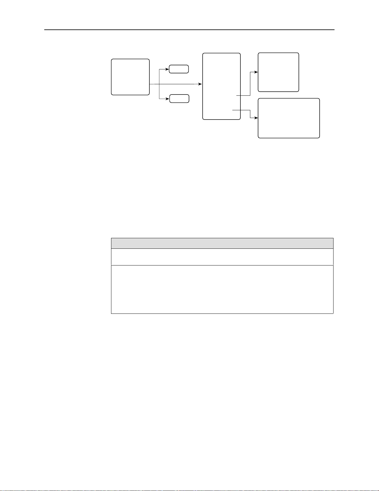
Configuration Option Tables
8
MAIN MENU
Status
Test
Configuration
Control
System Options Menu
For System Options, refer to Table A-1. To access the System Options screen,
follow this menu selection sequence:
Main Menu→Configuration→Load Configuration From→Edit→System
Table A-1. System Options (1 of 3)
Load
Save
Configuration
Edit/Display
• System
• Network
• Data Port
• User Interface
• Alarms & Traps
• SNMP &
Communication
User Interface
• T erminal Port
• Management Port
• External Device
• T elnet Session
SNMP & Communication
• Communication Protocol
• General SNMP Management
• SNMP NMS Security
• SNMP Traps
496-1517
Operating Mode
Possible Settings: DDS, LADS
Default Setting: DDS
The unit’s operating mode depends upon the DSU’s application.
DDS – Standard DDS network operation. The operating rate is either 56 kbps or
64 kbps CC.
LADS – The Local Area Data Set operating mode requires that the local and remote
units are connected directly to each other. This is a point-to-point application; also
known as LDM.
A-2
7610-A2-GB20-10November 1997
Page 62

Configuration Option Tables
Table A-1. System Options (2 of 3)
DDS Line Rate (Kbps)
Possible Settings: 56, 64CC, Autobaud
Default Setting: Autobaud
The unit starts up with Autobaud. When the DDS line rate obtained from the service
provider is detected, Autobaud is replaced with the actual rate.
DDS Line Rate (Kbps) option appears when Operating Mode is set to DDS.
NOTES: – Setting the actual data rate results in minimum power-up time. (If both
56 – 56 kbps line rate.
64CC – 64 kbps Clear Channel on a 72 kbps circuit.
Autobaud – This setting is automatically changed to the actual operating line rate of
56 kbps or 64CC as soon as the signal is detected.
LADS Timing
DSUs use Autobaud, the process can take several minutes.) Configure
the actual data rate after initial installation.
– The clock rates generated by the DSU at the DTE interface (TXC and
RXC) equal the operating rate minus the configured rate of 1600, 4000,
or 8000 bps for the IMC, if enabled. Refer to the In-Band Management
Channel Rate (bps) option in Table A-2.
Possible Settings: Internal, External, Receive
Default Setting: Internal
Determines the timing source for the unit.
LADS Timing option appears when Operating Mode is set to LADS.
Internal – Timing derived from the unit’s local clock. Use this setting for the LADS
primary timing unit that establishes the timing for both point-to-point units.
External – Timing is derived from the external clock provided by the DTE connected to
the V.35 interface on circuit CT113 (pins U, W).
NOTE: The valid rate generated by the DTE must be equal to the LADS line rate
Receive – Timing is derived from the line receive signal unless the unit is running
diagnostic tests. During the tests, the timing source is the internal clock. This setting
should be used for a LADS secondary timing unit.
LADS Line Rate (Kbps)
Possible Settings: 56, 64
Default Setting: 64
Line operating rate for LADS operation.
LADS Line Rate (Kbps) option appears when Operating Mode is set to LADS.
56 – 56 kbps line rate. Provides increased distance for the LADS applications.
64 – 64 kbps line rate.
minus the configured rate of 1600, 4000, or 8000 bps for the IMC, if
enabled. Refer to the In-Band Management Channel Rate (bps) option in
Table A-2.
7610-A2-GB20-10
November 1997
A-3
Page 63

Configuration Option Tables
Table A-1. System Options (3 of 3)
T est Timeout
Possible Settings: Enable, Disable
Default Setting: Enable
Allows user-initiated tests to end automatically . Recommend enabling when the unit is
managed remotely through the IMC to avoid the requirement to terminate the test
manually.
Enable – User-initiated loopback and pattern tests end when test duration is reached.
Disable – Tests can be terminated manually from the Network Tests screen. Refer to
the
Test Duration (min)
Possible Settings: 1–120
Default Setting: 10
Number of minutes for a test to be active before automatically ending.
1 to 120 – Amount of time in minutes for a user-initiated test to run before terminating.
Security Violation Alarm
Network Tests
NOTE: Tests commanded by the DTE or network-initiated tests are not affected by
Test Duration (min) option appears when Test Timeout is enabled.
section of Chapter 7.
this test timeout.
Possible Settings: Enable, Disable
Default Setting: Enable
Issues an alarm when access to the unit is attempted and fails.
Enable – Alarm generated when a security violation is detected. Refer to the
T rap: authentificationFailure
Disable – No alarm generated for a security violation.
section of Appendix D for possible alarm causes.
A-4
7610-A2-GB20-10November 1997
Page 64
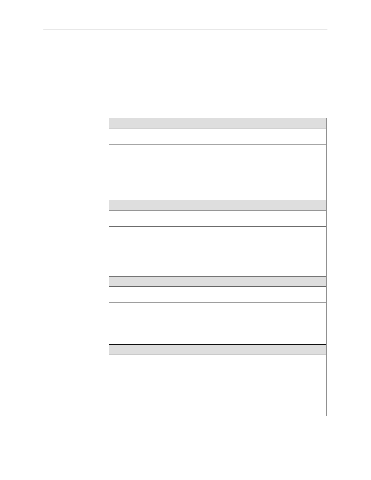
Network Interface Options Menu
For Network Interface Options, refer to Table A-2. To access the Network
Interface Options screen, follow this menu selection sequence:
Main Menu→Configuration→Load Configuration From→Edit→Network
Table A-2. Network Interface Options (1 of 4)
Network-initiated DSU Loopback (64K CC)
Possible Settings: Enable, Disable
Default Setting: Enable
Indicates whether the access unit responds to a DSU latching loopback sequence sent
by the network as specified by TR62310.
Network-initiated DSU Loopback (64K CC) option appears when Operating Mode
is set to DDS in Table A-1.
Enable – Responds to network-initiated commands to start and stop a latching DSU
loopback.
Disable – DSU will not respond to a DSU loopback initiated by the network.
Configuration Option Tables
Data Scrambling (64K CC)
Possible Settings: Enable, Disable
Default Setting: Disable
Data scrambling is used to suppress the possible simulation of network-initiated DSU
latching loopback commands by application data.
Data Scrambling (64K CC) option appears when Operating Mode is set to DDS in
Table A-1.
Enable – Enables data scrambling. The local and remote units must be set the same.
Disable – No data scrambling.
V.54 Initiated DSU Loopback
Possible Settings: Enable, Disable
Default Setting: Disable
When enabled, user data is looped back to the network when a V.54 Loop Up sequence
is received. The DSU loopback ends when a V.54 Loop Down sequence is detected.
Enable – DSU loopback can be initiated or terminated by a remote unit sending in-band
V.54 Loop 2 Up or Down sequences.
Disable – V.54 Loop 2 sequences are ignored.
In-Band Management Channel Rate (bps)
Possible Settings: Disable, 1600, 4000, 8000
Default Setting: Disable
The IMC provides a non-disruptive management channel to the remote DSU and uses a
portion of the DTE line rate.
Disable – The IMC is inactive.
1600, 4000, or 8000 – Sets the amount of the line rate in bps to allocate to the IMC.
NOTE: The local and remote units must be set the same.
7610-A2-GB20-10
November 1997
A-5
Page 65

Configuration Option Tables
Table A-2. Network Interface Options (2 of 4)
IMC IP Address
Possible Settings: 000.000.000.000 – 223.255.255.255, Clear
Default Setting: 000.000.000.000
Specifies the Internet Protocol address used to access the unit via the IMC interface.
000.000.000.000 – 223.255.255.255 – The range for the first byte is 000 to 223, with the
exception of 127. The range for the remaining three bytes is 000 to 255.
Clear – Clears the IMC IP address and sets to all zeros.
IMC Subnet Mask
Possible Settings: 000.000.000.000 – 255.255.255.255, Clear
Default Setting: 000.000.000.000
Specifies the subnet mask used to access the unit via the IMC interface.
000.000.000.000 – 255.255.255.255 – Set the IMC interface subnet mask. The range
for each byte is 000 to 255.
Clear – Clears the IMC Subnet Mask and sets to all zeros. When the subnet mask is all
zeros, the device creates a default subnet mask based on the class of IP address:
IMC Routing Information Protocol
IMC IP Address option does not appear when the In-Band Management Channel
Rate (bps) is disabled.
IMC Subnet Mask option does not appear when the In-Band Management
Channel Rate (bps) is disabled.
– Class A defaults to 255.000.000.000
– Class B defaults to 255.255.000.000
– Class C defaults to 255.255.255.000
Possible Settings: None, Proprietary
Default Setting: Proprietary
The RIP routes IMC management information between devices.
IMC Routing Information Protocol does not appear when the In-Band Management
Channel Rate (bps) option is disabled.
None – No routing protocol.
Proprietary – Uses proprietary variant of RIP Version 1 to enable the routing of
IP traffic between Paradyne devices.
Cross Pair Detection Alarm
Possible Settings: Enable, Disable
Default Setting: Enable
When a crossed pair condition is detected on the network interface, an ASCII alarm is
generated.
Cross Pair Detection Alarm option appears when the Operating Mode is set to
DDS in Table A-1.
Enable – Generates an ASCII alarm when a crossed pair condition is detected.
Disable – No ASCII alarm is generated.
NOTE: Additional settings are required to send out an ASCII alarm. Refer to the
Alarm Messages
section in Chapter 8.
A-6
7610-A2-GB20-10November 1997
Page 66

Configuration Option Tables
Table A-2. Network Interface Options (3 of 4)
No Signal Alarm
Possible Settings: Enable, Disable
Default Setting: Enable
When a NS condition is detected on the network interface, an ASCII alarm is generated.
Enable – Generates an ASCII alarm when a no signal condition is detected.
Disable – No ASCII alarm is generated.
NOTE: Additional settings are required to send out an ASCII alarm. Refer to the
Out of Service Alarm
Possible Settings: Enable, Disable
Default Setting: Enable
When an OOS condition is detected on the network interface, an ASCII alarm is
generated.
Out of Service Alarm option appears when the Operating Mode is set to DDS in
Enable – Generates an ASCII alarm when an out of service condition is detected.
Disable – No ASCII alarm is generated.
NOTE: Additional settings are required to send out an ASCII alarm. Refer to the
Alarm Messages
Table A-1.
Alarm Messages
section in Chapter 8.
section in Chapter 8.
Out of Frame Alarm
Possible Settings: Enable, Disable
Default Setting: Enable
When an OOF condition is detected on the network interface, an ASCII alarm is
generated.
Enable – Generates an ASCII alarm when an out of frame condition is detected on the
network interface.
Disable – No ASCII alarm is generated.
NOTE: Additional settings are required to send out an ASCII alarm. Refer to the
Excessive BPV Alarm
Possible Settings: Enable, Disable
Default Setting: Enable
When a Bipolar Violation condition is detected on the network interface, an ASCII alarm
is generated.
Enable – Generates an ASCII alarm when an excessive BPV condition is detected.
Disable – No ASCII alarm is generated.
NOTE: Additional settings are required to send out an ASCII alarm. Refer to the
Alarm Messages
Alarm Messages
section in Chapter 8.
section in Chapter 8.
7610-A2-GB20-10
November 1997
A-7
Page 67

Configuration Option Tables
Table A-2. Network Interface Options (4 of 4)
In-Band Framing Alarm
Possible Settings: Enable, Disable
Default Setting: Enable
When an in-band framing condition is detected on the network interface, an ASCII alarm
is generated.
Enable – Generates an ASCII alarm when a in-band framing condition is detected.
Disable – No ASCII alarm is generated.
In-Band Framing Alarm option does not appear when the In-Band Management
Channel Rate (bps) is disabled.
NOTE: Additional settings are required to send out an ASCII alarm. Refer to the
Alarm Messages
section in Chapter 8.
A-8
7610-A2-GB20-10November 1997
Page 68

Data Port Options Menu
For Data Port Options, refer to Table A-3. To access the Data Port Options
screen, follow this menu selection sequence:
Main Menu→Configuration→Load Configuration From→Edit→Data Port
Table A-3. Data Port Options (1 of 3)
Invert Transmit Clock
Possible Settings: Enable, Disable
Default Setting: Disable
The DSU clock provided on Interchange Circuit CT1 14, Transmit Signal Element Timing
DCE source (TXC), is phase inverted with respect to Interchange Circuit CT103,
Transmitted Data (TXD). Recommended when data errors are occurring due to long
cable lengths.
Enable – The DSU-supplied clock is phase inverted with respect to the transmitted data
TXD.
Disable – The clock supplied by the DSU on TXC is normal (i.e., not inverted).
Configuration Option Tables
Port (DTE) Initiated Loopbacks
Possible Settings: Disable, Local, Remote, Both
Default Setting: Disable
Specifies whether the DTE can initiate and terminate local and/or remote loopbacks.
The DTE loopback control is done through the Interchange Circuits specified by the
V.54 standard.
NOTE: Refer to the
Disable – No local or remote loopbacks can be initiated by the DTE.
Local – A local loopback can be controlled by the DTE, via the Interchange Circuit LL
(CT141), as specified by V.54. The DTE port remains in loopback as along as LL
remains on. Aborting the loopback from the A TI has no effect.
Remote – A remote digital loopback can be controlled by the DTE, via Interchange
Circuit RL (CT140), as specified by V.54. The remote equipment must be able to detect
the in-band V.54 loopback sequence.
Both – Both the local and remote loopbacks can be controlled by the DTE.
Bilateral Loopback
Possible Settings: Enable, Disable
Default Setting: Disable
When a DSU loopback is initiated, a local DTE loopback is also automatically initiated.
A Bilateral Loopback can be started by the A TI/NMS or by detection of a V.54 Loop 2 Up
sequence.
Enable – When Bilateral Loopback is enabled, running a DSU loopback also
automatically starts a local loopback. The local loopback ends when the DSU loopback
terminates.
Disable – Running a DSU loopback does not start a local loopback.
NOTE: Refer to the
Loopbacks
Loopbacks
section of Chapter 7.
and the
Network Tests
sections of Chapter 7.
7610-A2-GB20-10
November 1997
A-9
Page 69

Configuration Option Tables
Table A-3. Data Port Options (2 of 3)
Carrier Control by RTS
Possible Settings: Constant, Switched
Default Setting: Constant
Simulates Constant or Switched Carrier operation.
Constant – The internal RTS is forced on and the DSU is in a constant Data Mode on
the transmit line. The external RTS lead is ignored. The actual signal on the line is either
all ones (DMI) or DTE transmitted data.
Switched – RTS is monitored and CMI codes are transmitted when RTS is off.
CTS Control
Possible Settings: Standard, Follow RTS, Forced On, Circuit Assurance
Default Setting: Standard
Specifies the operation of the Interchange Circuit CT106, Clear to Send (CTS), which is
an output from the DSU.
Standard – CTS follows the internal RTS with a fixed delay, except that CTS will be off
when a network interface related alarm is detected or a test is active. The active test
may be initiated locally , remotely, or by the network.
Follow RTS – CTS follows the external RTS lead without delay, regardless of alarms
and tests.
Forced On – CTS is always forced on after the unit is powered up with a successful
self-test.
Circuit Assurance – With circuit assurance, CTS operates the same as the Standard
option, except that CTS will also be deasserted when CMI codes are being received.
Carrier Control by RTS option appears when In-Band Management Channel
Rate (bps) is disabled in Table A-2.
RLSD Control
Possible Settings: Standard, Forced On
Default Setting: Standard
Specifies the operation of the Interchange Circuit CT109, Received Line Signal Detector
(RLSD or CD), which is an output from the DSU.
Standard – RLSD is asserted when Data Mode is on the receive line. RLSD deasserts
when a DDS facility alarm is detected or the DSU is receiving CMI codes.
Forced On – RLSD is forced on after the unit is powered up with a successful self-test.
DSR Control
Possible Settings: Standard, Forced On, On During Test
Default Setting: Standard
Specifies the operation of the Interchange Circuit CT107, Data Set Ready (DSR), which
is an output from the DSU.
Standard – DSR is always asserted, except when a DDS facility alarm is reported or
the DSU is in Test mode.
Forced On – DSR is forced on after the unit is powered up with a successful self-test.
On During Test – DSU operates the same as the Standard option, except that DSR
remains asserted when the DSU is in Test mode to allow the DTE to send test patterns.
A-10
7610-A2-GB20-10November 1997
Page 70
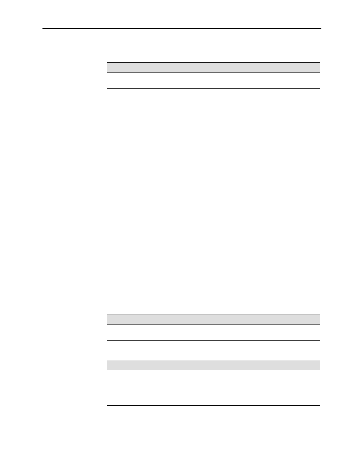
Table A-3. Data Port Options (3 of 3)
Monitor DTR
Possible Settings: Enable, Disable
Default Setting: Enable
Indicates to the DSU whether to monitor the Interchange Circuit CT108, Data Terminal
Ready (DTR), from the DTE.
Enable – The DSU monitors the state of DTR on the User Data (DTE) port. Based on
the Link Traps option setting in Table A-12, the DSU uses the DTR circuit to trigger a
Link Up/Down SNMP trap and a Health and Status message.
Disable – DTR is not monitored by the DSU. Use when a DTE does not provide the
DTR lead at the interface.
User Interface Options Menu
The User Interface Options Menu includes the following:
Configuration Option Tables
Terminal Port Options
To access the Terminal Port Options screen, follow this menu selection sequence:
Terminal Port Options, Table A-4
Management Port Options, Table A-5
External Device Options, Table A-6
Telnet Session Options, Table A-7
Main Menu→Configuration→Load Configuration From→Edit
User Interface→Terminal Port
Table A-4. Terminal Port Options (1 of 3)
Data Rate (Kbps)
Possible Settings: 2.4, 4.8, 9.6, 14.4, 19.2, 28.8, 38.4
Default Setting: 9.6
Data rate in kbps on the Terminal port.
2.4 to 38.4 – Selects a Terminal port data rate from 2.4 to 38.4 kbps.
Character Length
→
7610-A2-GB20-10
Possible Settings: 7, 8
Default Setting: 8
Specifies the number of bits needed to represent one character, including the parity bit.
7 or 8 – Sets the bits per character.
November 1997
A-11
Page 71

Configuration Option Tables
Table A-4. Terminal Port Options (2 of 3)
Parity
Possible Settings: None, Even, Odd
Default Setting: None
Specifies Parity for the Terminal port.
None – Provides no parity.
Even – Parity is even.
Odd – Parity is odd.
Stop Bits
Possible Settings: 1, 1.5, 2
Default Setting: 1
Provides the number of stop bits for the Terminal port.
1, 1.5, or 2 – Selects the number of stop bits.
Monitor DTR
Possible Settings: Enable, Disable
Default Setting: Enable
Specifies monitoring of the Data Terminal Ready (DTR) control lead.
Enable – Standard operation of the DTR control lead.
Disable – DTR is ignored. Some external device connections may require this setting.
Login Required
Possible Settings: Enable, Disable
Default Setting: Disable
Used to secure access to the ATI through the Terminal port. Login IDs are created with
a password and access level.
Enable – Security is enabled. When ATI access is attempted through the Terminal port,
a screen appears that requires a Login ID and password.
Disable – Main menu appears with no Login required.
NOTE: Refer to the
Port Access Level
Possible Settings: Level 1, Level 2, Level 3
Default Setting: Level 1
The Terminal port access level is interrelated with the access level of the Login ID.
Level 1 – This is the highest access level. If Login Required is disabled, the Terminal
port access is level 1. If Login Required is enabled, the effective level is the Login ID
access level.
Level 2 – This access level overrides a Login ID with an access level 1. If a Login ID
has an access level of 3, the effective access level is 3.
Level 3 – This access level becomes the effective access level and overrides a Login
ID with an access level of 1 or 2.
NOTE: Refer to the
Creating a Login
ATI Access
section of Chapter 4 for access level details.
section of Chapter 4.
A-12
7610-A2-GB20-10November 1997
Page 72
Configuration Option Tables
Table A-4. Terminal Port Options (3 of 3)
Inactivity Timeout
Possible Settings: Enable, Disable
Default Setting: Disable
Provides automatic logoff of an ATI session through the Terminal Port. When the
session is closed, User Interface Idle appears on the screen and the unit toggles the
Terminal port DSR lead.
Enable – The A TI session terminates automatically after the Disconnect Time set in the
next option. When the session was occurring over an external modem connected to the
Terminal port, the modem will interpret the DSR toggle as DTR being dropped and
disconnect.
Disable – An A TI session through the Terminal port will remain active indefinitely.
Disconnect Time(minutes)
Possible Settings: range 1 – 60
Default Setting: 5
Number of minutes of inactivity before the A TI session terminates automatically.
Timeout is based on no keyboard activity.
Disconnect Time(minutes) option appears when Inactivity Timeout is enabled.
1 to 60 – The ATI user session is closed after the selected number of minutes.
Management Port Options
To access the Management Port Options screen, follow this menu selection
sequence:
Main Menu→Configuration→Load Configuration From→Edit
User Interface→Management Port
Table A-5. Management Port Options (1 of 3)
Port Use
Possible Settings: Net Link, Alarms, None
Default Setting: Net Link
The Management port provides a choice of functions.
Net Link – The Management port is the network communication link and provides
connectivity to an IP network to support SNMP managers and Telnet sessions.
Alarms – The Management port is dedicated as an alarm port and sends out ASCII
alarm messages.
None – Disables the Management port.
No other fields in this table will appear when set to None.
→
7610-A2-GB20-10
November 1997
A-13
Page 73

Configuration Option Tables
Table A-5. Management Port Options (2 of 3)
Port Type
Possible Settings: Asynchronous, Synchronous
Default Setting: Synchronous
Establishes asynchronous or synchronous communication for the Management port.
Asynchronous – Port set for asynchronous communication.
Synchronous – Port set for synchronous communication.
Clock Source
Possible Settings: Internal, External
Default Setting: Internal
Specifies internal or external clocking.
Internal – Clocking is provided internally.
External – Clocking is provided externally. The Management port is always defined as a
DCE. This option setting forces the Management port to use external transmit clocking
(XTXC or TT) from a connected device (DTE).
Port Type option can be changed only when Port Use is set to Net Link.
Asynchronous displays when Port Use is set to Alarms and cannot be changed.
Clock Source option appears when Port Type is set to Synchronous.
Data Rate (Kbps)
Possible Settings: 2.4, 4.8, 9.6, 14.4, 19.2, 28.8, 38.4
Default Setting: 9.6
Specifies the Management port data rate in kbps.
Data Rate (Kbps) option does not appear when Port Type is set to Synchronous
with Clock Source set to External.
2.4 to 38.4 – Selects a Management port data rate from 2.4 to 38.4 kbps.
2.4 kbps and 4.8 kbps only appear when Port Type is set to Asynchronous.
Character Length
Possible Settings: 7, 8
Default Setting: 8
Specifies the number of bits needed to represent one character.
Character Length option appears when Port Type is set to Asynchronous.
7 or 8 – Sets the bits per character.
Parity
Possible Settings: None, Even, Odd
Default Setting: None
Specifies the Parity on the Management port.
Parity option appears when Port Type is set to Asynchronous.
None – Provides no parity.
Even – Parity is even.
Odd – Parity is odd.
A-14
7610-A2-GB20-10November 1997
Page 74
Configuration Option Tables
Table A-5. Management Port Options (3 of 3)
Stop Bits
Possible Settings: 1, 1.5, 2
Default Setting: 1
Provides the number of stop bits for the Management port.
Stop Bits option appears when Port Type is set to Asynchronous.
1, 1.5, or 2 – Selects the number of stop bits.
Monitor DTR
Possible Settings: Enable, Disable
Default Setting: Enable
Specifies monitoring of the Data Terminal Ready (DTR) control lead.
Monitor DTR option appears when Port Type is set to Asynchronous.
Enable – Standard operation of the DTR control lead.
Disable – DTR is ignored. Some external device connections may require this setting.
Routing Information Protocol
Possible Settings: None, Proprietary
Default Setting: None
Specifies the routing protocol between devices through the Management port.
Routing Information Protocol appears when Port Use is set for Net Link.
None – No routing protocol; use None when the device connected to the Management
port is not a Model 7610.
Proprietary – Uses proprietary variant of RIP Version 1 to enable the routing of IP
traffic between Paradyne devices.
External Device Options for the Management Port
To access the External Device Options screen, follow this menu selection
sequence:
Main Menu→Configuration→Load Configuration From→Edit
User Interface→External Device
7610-A2-GB20-10
November 1997
→
A-15
Page 75

Configuration Option Tables
Table A-6. External Device Options (1 of 3)
External Device Commands
Possible Settings: Disable, AT, Other
Default Setting: Disable
Specifies the type of external device commands to be sent out the Management port.
Disable – No external device commands will be sent out the Management port.
AT – Standard AT commands are sent out the Management port to control an external
device, such as a modem. When establishing a connection, the A T dial command “ATD”
will precede the phone number from the dial directory .
Other – Commands configured by the user are sent out the Management port.
Dial-In Access
NOTE: The Management port DTR lead is monitored to detect loss of the external
device connection. The external device DSR lead must be connected to the
Management port’s DTR lead, via a standard EIA-232 crossover cable, and
the device must be configured to wink DSR on disconnect.
No other options in this table will appear.
The next option, Dial-In Access, is available when External Device Commands is
set to A T; no other options in this table will appear.
Possible Settings: Enable, Disable
Default Setting: Disable
Controls external device dial-in access through the Management port.
Dial-In Access option appears when External Device Commands is set to AT.
Enable – Answers incoming calls from an external device and establishes a connection
to a remote terminal or IP network. Refer to the Port Use option in Table A-5 for the
Management port functions.
Disable – Incoming calls from an external device are not answered.
Connect Prefix
Possible Settings: ASCII Text, Clear
Default Setting: [blank]
The connect prefix and directory phone number are used to establish a connection. The
connection can be initiated by the user or automatically established for dial out of ASCII
alarms or SNMP traps.
Connect Prefix option appears when External Device Commands is set to Other.
ASCII Text – Places a prefix in front of the phone number. Enter a maximum of
20 characters. Refer to the
Clear – Clears the field and sets to none.
ASCII Characters
section.
A-16
7610-A2-GB20-10November 1997
Page 76

Configuration Option Tables
Table A-6. External Device Options (2 of 3)
Connect Indication String
Possible Settings: ASCII Text, Clear
Default Setting: [blank]
Determines if a connection is established. The DSU searches the Management port
receive data stream for the connect indication string, and if not received within one
minute, the connection times out. The connection can be initiated by the user or
automatically established to dial out ASCII alarms or SNMP traps.
Connects Indication String option appears when External Device Commands is set
to Other.
ASCII Text – Enter a maximum of 20 characters. Refer to the
for valid ASCII characters and control sequences.
Clear – Clears the field and sets to no string. The port’s RTS lead will be used to
determine that a connection has been established.
Escape Sequence
Possible Settings: ASCII Text, Clear
Default Setting: [blank]
When an external device connection is established, the Escape Sequence can be used
to switch an external device to command mode before sending the disconnect
command. Refer to Escape Sequence Delay (sec) for delay before and after the Escape
Sequence.
Escape Sequence option appears when External Device Commands is set to
Other.
ASCII Text – Enter a maximum of 20 characters. Refer to the
for valid ASCII characters and control sequences.
Clear – Clears the field and sets the escape sequence to none.
ASCII Characters
ASCII Characters
section
section
Escape Sequence Delay (sec)
Possible Settings: None, 0.2, 0.4, 0.6, 0.8, 1.0
Default Setting: None
Amount of delay before sending the first character of the escape sequence and after
sending the last character. The escape sequence is entered in the previous option.
During this delay , no data is sent out the Management port.
Escape Sequence Delay (sec) option appears when External Device Commands
is set to Other.
None – No Management port escape sequence delay .
0.2 to 1.0 – Amount of delay in seconds before and after an escape sequence. The
delay must be equal to or greater than the escape guard time of the external device.
7610-A2-GB20-10
November 1997
A-17
Page 77
Configuration Option Tables
Table A-6. External Device Options (3 of 3)
Disconnect String
Possible Settings: ASCII Text, Clear
Default Setting: [blank]
The Disconnect String specifies the command used to disconnect an external device.
The external device must be in command mode, so the Escape Sequence is always
sent before the Disconnect String.
ASCII Text – Enter a maximum of 20 characters. Refer to the
for valid ASCII characters and control sequences.
Clear – Clears the field and sets to no string. The Management port DSR lead is used
to force a disconnect.
Telnet Session Options
Disconnect String option appears when External Device Commands is set to
Other.
ASCII Characters
section
To access the Telnet Session Options screen, follow this menu selection
sequence:
Main Menu→Configuration→Load Configuration From→Edit
→
User Interface→Telnet Session
Table A-7. Telnet Session Options (1 of 2)
T elnet Session
Possible Settings: Enable, Disable
Default Setting: Disable
Specifies if the DSU will respond to a Telnet session request from a T elnet client on an
interconnected IP network.
Enable – Allows Telnet sessions between the unit and a Telnet client.
Disable – No Telnet sessions allowed.
Login Required
Possible Settings: Enable, Disable
Default Setting: Disable
Used to secure access to the A TI through a Telnet session. Login IDs are created with a
password and access level. Refer to the
Enable – Security is enabled. When access is attempted via Telnet, the user is
prompted for a Login ID and password.
Disable – No Login required for a Telnet session.
Creating a Login
section of Chapter 4.
A-18
7610-A2-GB20-10November 1997
Page 78
Configuration Option Tables
Table A-7. Telnet Session Options (2 of 2)
Session Access Level
Possible Settings: Level 1, Level 2, Level 3
Default Setting: Level 1
The Telnet session access level is interrelated with the access level of the Login ID.
Level 1 – This is the highest access level. Access level is determined by the Login ID. If
Login Required is disabled, the session access is level 1.
Level 2 – This access level overrides a Login ID with an access level 1. If a Login ID
has an access level of 3, the effective access level is 3.
Level 3 – This access level provides the effective access level and overrides the
access level of a Login ID.
NOTE: Refer to the
Inactivity Timeout
Possible Settings: Enable, Disable
Default Setting: Disable
Provides automatic logoff of a Telnet session.
Enable – The Telnet session terminates automatically after the Disconnect Time set in
the next option.
Disable – A Telnet session will not be closed due to inactivity.
ATI Access
section of Chapter 4 for access level details.
Disconnect Time (minutes)
Possible Settings: range 1 – 60
Default Setting: 5
Number of minutes of inactivity before a Telnet session terminates automatically.
Timeout is based on no keyboard activity.
Disconnect Time (minutes) option appears when Inactivity Timeout is enabled.
1 to 60 – The Telnet session is closed after the selected number of minutes.
7610-A2-GB20-10
November 1997
A-19
Page 79

Configuration Option Tables
Alarms & Traps Options Menu
For Alarms & Traps Options, refer to Table A-8. To access the Alarms & Traps
Options screen, follow this menu selection sequence:
Main Menu→Configuration→Load Configuration From→Edit
→
Alarms & Traps
Table A-8. Alarms & Traps Options (1 of 2)
ASCII Alarm Messages
Possible Settings: Enable, Disable
Default Setting: Disable
Controls the generation and routing of ASCII alarm messages to an ASCII terminal or
printer connected to the Management port. Refer to the
Chapter 8.
Enable – ASCII alarm messages are generated and sent out when the Management
port is configured for Alarms in Management Port Options, Table A-5.
The messages are sent out immediately if there is:
– No DCE (e.g., modem or PAD) connected to the Management port and
External Device Commands option is set to Disable in Table A-6 or
– An active connection is already established via an external DCE.
If an external device is connected to the Management port with no active
connection, the message control is based on the next option, Alarm & Trap
Dial-Out. External Device Commands must be configured for A T or Other in
External Device Options, Table A-6.
Disable – ASCII alarm messages are not generated or sent.
Alarm & Trap Dial-Out
Alarm Messages
section of
Possible Settings: Enable, Disable
Default Setting: Disable
When there is no active connection, this option controls whether generating an ASCII
alarm or SNMP trap results in automatic call initiation.
Enable – Automatically places a call via the external device connected to the
Management port.
To send out SNMP traps, SNMP Management must be enabled in Table A-10.
When Port Use is set to Net Link in Table A-5, up to ten SNMP traps are queued
at the interface.
The Primary Directory phone number is dialed. Refer to the
Chapter 3.
Refer to the Call Retry option for handling of incomplete call attempts.
Disable – Automatic call initiation is disabled and alarm messages are discarded.
SNMP traps are retained until a connection is established.
Call Setup
section of
A-20
7610-A2-GB20-10November 1997
Page 80
Configuration Option Tables
Table A-8. Alarms & Traps Options (2 of 2)
SNMP Trap Disconnect
Possible Settings: Enable, Disable
Default Setting: Enable
Determines if a Management port external device connection is dropped after sending
an SNMP trap.
A call established to send out an ASCII alarm always disconnects automatically if
the call was initiated automatically .
Enable – The external device disconnects after sending out an SNMP trap.
Disable – The external device remains connected and must be disconnected by remote
modem or manually. This allows the NMS to poll the DSU after receiving an SNMP trap.
Call Retry
Possible Settings: Enable, Disable
Default Setting: Disable
Specify if an unsuccessful call is retried.
Enable – The call is retried up to five times for each ASCII alarm and each SNMP trap.
The following options, Dial-Out Delay Time (min) and Alternate Dial-Out Directory,
affect the amount of time before a retry and the number of retries.
Disable – No retry of an unsuccessful call.
Dial-Out Delay Time (min)
Possible Settings: 1, 2, 3, 4, 5, 6, 7, 8, 9, 10
Default Setting: 5
This delay applies to both the number of minutes before a new call is initiated for a
different alarm and the number of minutes between call retries. Refer to the previous
option, Call Retry.
1 to 10 – Number of minutes before a call is initiated or retried.
Alternate Dial-Out Directory
Possible Settings: Enable, Disable
Default Setting: Disable
Specifies whether an incomplete call initiated for an ASCII alarm or SNMP trap is
attempted using the Alternate Directory phone number.
Both Alarm & Trap Dial-Out and Call Retry options must be enabled.
Enable – After attempting to reach the Primary Directory phone number five times, the
alternate dial-out directory phone number is dialed five times.
NOTE: The Alternate Directory phone number is dialed. Refer to the
section of Chapter 3.
Disable – No alternate phone number is used.
Call Setup
7610-A2-GB20-10
November 1997
A-21
Page 81

Configuration Option Tables
SNMP & Communication Options Menu
The SNMP & Communications Menu includes the following:
Communication Protocol Options, Table A-9
General SNMP Management Options, Table A-10
SNMP NMS Security Options, Table A-11
SNMP Traps Options, Table A-12
Communication Protocol Options
To access the Communication Protocol Options screen, follow this menu
selection sequence:
Main Menu→Configuration→Load Configuration From→Edit
→
SNMP & Communication→Communication Protocol
Table A-9. Communication Protocol Options (1 of 2)
Management Port IP Address
Possible Settings: 000.000.000.000 – 223.255.255.255, Clear
Default Setting: 000.000.000.000
Specifies the Internet Protocol address for the Management port.
Port Use option must be set to Net Link in Table A-5 for the Management Port IP
Address to be effective.
000.000.000.000 – 223.255.255.255 – Sets the Management port IP address. The
range for the first byte is 000 to 223, with the exception of 127. The range for the
remaining three bytes is 000 to 255.
Clear – Clears the IP address and sets to all zeros.
NOTE: This IP address is also used if the Alternate Directory Phone Number is
Management Port Subnet Mask
Possible Settings: 000.000.000.000 – 255.255.255.255, Clear
Default Setting: 000.000.000.000
Specifies the subnet mask needed to access the Management port.
000.000.000.000 – 255.255.255.255 – Set the Management port subnet mask. The
range for each byte is 000 to 255.
Clear – Clears the subnet mask and sets to all zeros. When the subnet mask is all
zeros, the device creates a default subnet mask based on the class of IP address:
– Class A defaults to 255.000.000.000
– Class B defaults to 255.255.000.000
– Class C defaults to 255.255.255.000
attempted and the Alternate Mgmt Port IP Address option is all zeros.
A-22
7610-A2-GB20-10November 1997
Page 82

Configuration Option Tables
Table A-9. Communication Protocol Options (2 of 2)
Management Port Link Protocol
Possible Settings: PPP, SLIP
Default Setting: PPP
Specifies the link layer protocol for the Management port.
Port Use option must be set to Net Link in Table A-5 for the Management Port Link
Protocol to be effective.
PPP – Point-to-Point Protocol.
SLIP – Serial Line Internet Protocol.
Port Type option must be set to Asynchronous in Table A-5.
Alternate Mgmt Port IP Address
Possible Settings: 000.000.000.000 – 223.255.255.255, Clear
Default Setting: 000.000.000.000
IP address to use when a call is initiated using the Alternate Directory Phone Number. If
this address is all zeros, the Management Port IP Address is used.
000.000.000.000 – 223.255.255.255 – Sets the alternate Management port IP address.
The range for the first byte is 000 to 223, with the exception of 127. The range for the
remaining three bytes is 000 to 255.
Clear – Clears the IP address and sets to all zeros.
Alternate Mgmt Port Subnet Mask
Possible Settings: 000.000.000.000 – 255.255.255.255, Clear
Default Setting: 000.000.000.000
Specifies the alternate subnet mask used to access the Management port. Used with
the previous option, Alternate Management Port IP Address.
000.000.000.000 – 255.255.255.255 – Sets the management port alternate subnet
mask. The range for each byte is 000 to 255.
Clear – Clears the alternate subnet mask and sets to all zeros. The device creates a
default alternate subnet mask based on the class of IP address:
– Class A defaults to 255.000.000.000
– Class B defaults to 255.255.000.000
– Class C defaults to 255.255.255.000
Default Network Destination
Possible Settings: None, Mgmt, IMC
Default Setting: None
Specifies where the default network is connected. The routing protocol uses this option
to route data with no specific route.
WARNING: Unroutable data is discarded if the Default Network Destination
None – No default network destination; unroutable data is discarded.
Mgmt – The Management port is the default network destination.
Port Use option must be set to Net Link in Table A-5.
IMC – The In-Band Management Channel is the default network destination.
In-Band Management Channel Rate(bps) option must be set to 1600, 4000, or
8000 bps in Table A-2.
becomes disabled or the option is set to None. Change the default
network destination if the default route is not operational.
7610-A2-GB20-10
November 1997
A-23
Page 83

Configuration Option Tables
General SNMP Management Options
To access the General SNMP Management Options screen, follow this menu
selection sequence:
Main Menu→Configuration→Load Configuration From→Edit
→
SNMP & Communication→General SNMP Management
Table A-10. General SNMP Management Options (1 of 2)
SNMP Management
Possible Settings: Enable, Disable
Default Setting: Disable
Specifies if the DSU can be managed by an SNMP NMS or send out SNMP traps.
Enable – Enables SNMP management.
Disable – DSU does not respond to SNMP messages or send out SNMP traps.
Community Name 1
Possible Settings: ASCII Text, Clear
Default Setting: Public
Community Name of external SNMP Managers allowed access to the DSU’s MIB. This
community name must be supplied by an external SNMP manager attempting to access
a MIB object. Level of access is set in the next option, Name 1 Access.
ASCII Text – Enter a maximum of 255 ASCII printable characters. Refer to the
Characters
Clear – Clears the Community Name 1 field.
Name 1 Access
section.
ASCII
Possible Settings: Read, Read/Write
Default Setting: Read
Set the access level for the Community Name 1 created in the previous option.
Read – Allows a read-only access (i.e. SNMP Get) to accessible MIB objects.
Read/Write – Allows both an SNMP Get and Set to MIB objects. Write access allowed
to all MIB objects specified as read-write in the MIB RFC.
Community Name 2
Possible Settings: ASCII Text, Clear
Default Setting: [blank]
Community Name of external SNMP Managers allowed access to the DSU’s MIB. This
community name must be supplied by an external SNMP manager attempting to access
a MIB object. Level of access is set in the next option, Name 2 Access.
ASCII Text – Enter a maximum of 255 ASCII printable characters. Refer to the
Characters
Clear – Clears the Community Name 2 field.
section.
ASCII
A-24
7610-A2-GB20-10November 1997
Page 84
Table A-10. General SNMP Management Options (2 of 2)
Name 2 Access
Possible Settings: Read, Read/Write
Default Setting: Read
Set the access level for the Community Name 2 created in the previous option.
Read – Allows a read-only access (i.e. SNMP Get) to accessible MIB objects.
Read/Write – Allows both an SNMP Get and Set to MIB objects. Write access allowed
to all MIB objects specified as read-write in the MIB RFC.
SNMP NMS Security Options
To access the SNMP NMS Security Options screen, follow this menu selection
sequence:
Configuration Option Tables
Main Menu→Configuration→Load Configuration From→Edit
→
SNMP & Communication→SNMP NMS Security
Table A-11. SNMP NMS Security Options (1 of 2)
NMS IP Validation
Possible Settings: Enable, Disable
Default Setting: Disable
Determines if security checks are performed on the IP address of any SNMP
management system that attempts to access the node.
Enable – Performs security checking. Allows access only if the sending manager’s
IP address has been entered on the NMS IP address list below.
Disable – No security checking of incoming SNMP messages.
Number of Managers
Possible Settings: 1, 2, 3, 4, 5, 6, 7, 8, 9, 10
Default Setting: 1
Set the number of SNMP managers that are authorized to send SNMP messages. The
IP address of each SNMP management system must be entered in the next option.
1 to 10 – Specifies the number of SNMP managers allowed to send SNMP messages.
7610-A2-GB20-10
November 1997
A-25
Page 85

Configuration Option Tables
Table A-11. SNMP NMS Security Options (2 of 2)
NMS n IP Address
Possible Settings: 000.000.000.000 – 223.255.255.255, Clear
Default Setting: 000.000.000.000
Enter an IP address for each of the managers set in the previous option. “n” is the
number of the manager (1 to 10). Use the next option to establish the security level for
each SNMP manager.
000.000.000.000 – 223.255.255.255 – Sets the NMS IP address. The range for the first
byte is 000 to 223, with the exception of 127. The range for the remaining three bytes is
000 to 255.
Clear – Clears the IP address and sets to all zeros.
Access Level
Possible Settings: Read, Read/Write
Default Setting: Read
Set the access level for each IP address created in the previous option.
Read – Allows a read-only access (SNMP Get) to accessible MIB objects.
Read/Write – Allows both an SNMP Get and Set to MIB objects. Write access allowed
to all MIB objects specified as read-write in the MIB RFC. This access level is overriden
by the Community Name’s access level for the SNMP Manager , if the Community Name
access level is Read.
NOTE: When an SNMP message is received from an IP address that does not
match the IP address entries in this option, access is denied and an
“authenticationFailure” trap is generated.
A-26
7610-A2-GB20-10November 1997
Page 86

SNMP Traps Options
Configuration Option Tables
To access the SNMP Traps Options screen, follow this menu selection sequence:
Main Menu→Configuration→Load Configuration From→Edit
→
SNMP & Communication→SNMP Traps
Table A-12. SNMP Traps Options (1 of 2)
SNMP Traps
Possible Settings: Enable, Disable
Default Setting: Disable
Controls the generation of SNMP trap messages. The options for addresses and types
of traps are located in this table.
SNMP Management must be enabled in Table A-10.
Enable – SNMP trap messages are sent out to SNMP managers.
If the destination is the Management port and an external device is attached to the
Management port, the messages are sent immediately if there is an active
connection. Automatic call initiation is based on the Alarm & Trap Dial-Out option
in Table A-8. The destination is set with the Trap Manager Destination option.
Disable – No SNMP trap messages are sent out.
Number of Trap Managers
Possible Settings: 1, 2, 3, 4, 5, 6
Default Setting: 1
Sets the number of SNMP management systems that will receive SNMP traps.
1 to 6 – Number of trap managers. An NMS IP address is required for each manager.
Trap Manager “n” IP Address
Possible Settings: 000.000.000.000 – 223.255.255.255, Clear
Default Setting: 000.000.000.000
Specifies the Internet Protocol address used to identify each SNMP trap manager.
n
” represents the number of the manager (from 1 to 6).
“
000.000.000.000 – 223.255.255.255 – Enter an address for each SNMP trap manager.
The range for the first byte is 000 to 223, with the exception of 127. The range for the
remaining three bytes is 000 to 255.
Clear – Clears the IP address and sets to all zeros.
Trap Manager “n” Destination
Possible Settings: Default, Mgmt, IMC
Default Setting: Default
Provides the network destination path of each trap manager. “n” is the number of the
manager (from 1 to 6).
Default – Uses the address set in the Default Network Destination in Table A-9.
Mgmt – The Management port is the network destination.
Port Use option must be set to Net Link in Table A-5.
IMC – The In-Band Management Channel is the default network destination.
In-Band Management Channel Rate(bps) option must be set to 1600, 4000, or
8000 bps in Table A-2.
7610-A2-GB20-10
November 1997
A-27
Page 87

Configuration Option Tables
Table A-12. SNMP Traps Options (2 of 2)
General Traps
Possible Settings: Disable, Warm, AuthFail, Both
Default Setting: Both
Determines which SNMP traps are sent to each trap manager.
Disable – No general trap messages are sent.
Warm – Sends trap message for “
AuthFail – Sends trap message for “
Both – Sends both trap messages.
Enterprise Specific Traps
Possible Settings: Enable, Disable
Default Setting: Disable
This option is used to determine if SNMP traps are generated for enterprise-specific
events.
Enable – SNMP traps are generated for enterprise-specific events.
Disable – No enterprise-specific event traps are sent.
Link Traps
NOTE: Refer to
NOTE: Refer to the
Standards Compliance for SNMP Traps
warmStart”
.
authenticationFailure
Traps: Enterprise Specific
”.
, Appendix D.
section of Appendix D.
Possible Settings: Disable, Up, Down, Both
Default Setting: Both
This option is used to determine if SNMP traps are generated for link up and link down
for one of the communication interfaces.
Disable – No linkUp or linkDown SNMP traps are generated.
Up – A linkUp trap is generated when the DSU recognizes that one of the
communication interfaces is operational.
Down – A linkDown trap is generated when the DSU recognizes a failure in one of the
communication interfaces.
Both – Sends trap messages for detection of both linkUp and linkDown.
NOTE: Refer to the
Link Trap Interfaces
Possible Settings: Network, Port, Both
Default Setting: Both
This option determines if the SNMP linkUp, SNMP linkDown, and interface-related
enterprise-specific traps are generated for the DDS Network Interface and/or User Data
(DTE) port.
NOTE: These traps are not supported on the Management port and Terminal port.
Network – SNMP trap messages are generated for the DDS network interface.
Port – SNMP trap messages are generated for the User Data (DTE) port.
Both – SNMP trap messages are generated on both the DDS network interface and the
User Date (DTE) port.
Traps: linkUp and linkDown
section of Appendix D.
A-28
7610-A2-GB20-10November 1997
Page 88

ASCII Characters
ASCII characters are divided into ASCII printable characters and ASCII
non-printable control sequences.
ASCII printable characters include:
Numeric 0–9
Upper or lower case A-Z
< > space
All ASCII symbols except the ^ (caret)
ASCII printable characters are valid entries for the following:
Configuration Option Tables
Device Name screen. Refer to the
section in Chapter 3.
— Device Name field
— System Name field
— System Location field
— System Contact field
Call Directories screen. Refer to the
— Phone Number field
Administer Logins screen. Refer to the
— Login ID field
— Password field
External Device Options, Table A-6
— Connect Prefix option
— Connects Indication String option
— Escape Sequence option
— Disconnect String option
Entering Device and System Information
Call Setup
section in Chapter 3.
Creating a Login
section in Chapter 4.
7610-A2-GB20-10
General SNMP Management Options, Table A-10
— Community Name 1 option
— Community Name 2 option
November 1997
A-29
Page 89

Configuration Option Tables
Table A-13 contains non-printable ASCII characters. To form a control sequence,
the caret (^) must be followed by one character. In addition to ASCII printable
characters, these control sequences are also valid entries in the following:
Call Directories screen. Refer to the
Call Setup
section in Chapter 3.
— Phone Number field
External Device Options, Table A-6
— Connect Prefix option
— Connects Indication String option
— Escape Sequence option
— Disconnect String option
Table A-13. ASCII Non-Printable Characters
Sequence
^A or ^a SOH 0x01 ^Q or ^q DC1 0x11
^B or ^b STX 0x02 ^ R or ^r DC2 0x12
^C or ^c ETX 0x03 ^S or ^s DC3 0x13
^D or ^d EOT 0x04 ^T or ^t DC4 0x14
^E or ^e ENQ 0x05 ^U or ^u NAK 0x15
^F or ^f ACK 0x06 ^V or ^v SYN 0x17
ASCII Hex Sequence ASCII Hex
^G or ^g BEL 0x07 ^W or ^w ETB 0x17
^H or ^h BS 0x08 ^X or ^x CAN 0x18
^I or ^i HT 0x09 ^Y or ^y EM 0x19
^J or ^j LF or NL 0x0A ^Z or ^z SUB 0x1A
^K or ^k VT 0x0B ^{ or ^[ ESC 0x1B
^L or ^l FF or NP 0x0C ^\ or ^| FS 0x1C
^M or ^m CR 0x0D ^] or ^} GS 0x1D
^N or ^n SO 0x0E ^^ or ^~ RS 0x1E
^O or ^o SI 0x0F ^- US 0x1F
^P or ^p DLE 0x10
A-30
7610-A2-GB20-10November 1997
Page 90

Worksheets
Overview
The worksheets in this appendix summarize the configuration options accessed
when you select Configuration on the Main Menu. The possible menu selections
are displayed with the default settings and the possible settings.
Configuration Worksheets
B
System
Configuration Option Settings
Operating Mode [DDS], LADS
DDS Line Rate (Kbps) 56, 64CC, [Autobaud]
LADS Timing [Internal], External, Receive
LADS Line Rate (Kbps) 56, [64]
Test Timeout [Enable], Disable
Test Duration (min) 1–120, [10]
Security Violation Alarm [Enable], Disable
Default in [Bold]
7610-A2-GB20-10
November 1997
B-1
Page 91

Worksheets
Network Interface
Configuration Option Settings
Network-initiated DSU Loopback (64K CC) [Enable], Disable
Data Scrambling (64K CC) Enable, [Disable]
V.54 Initiated DSU Loopback Enable, [Disable]
In-Band Management Channel Rate (bps) [Disable], 1600, 4000, 8000
IMC IP Address [000.000.000.000] – 223.255.255.255
IMC Subnet Mask [000.000.000.000] – 255.255.255.255
IMC Routing Information Protocol None, [Proprietary]
Cross Pair Detection Alarm [Enable], Disable
No Signal Alarm [Enable], Disable
Out of Service Alarm [Enable], Disable
Out of Frame Alarm [Enable], Disable
Excessive BPV Alarm [Enable], Disable
In-Band Framing Alarm [Enable], Disable
Default in [Bold]
Data Port
Configuration Option Settings
Invert Transmit Clock Enable, [Disable]
Port (DTE) Initiated Loopbacks [Disable], Local, Remote, Both
Bilateral Loopback Enable, [Disable]
Carrier Control by RTS [Constant], Switched
CTS Control [Standard], Follow RTS, Forced On,
Circuit Assurance
RLSD Control [Standard], Forced On
DSR Control [Standard], Forced On, On During Test
Monitor DTR [Enable], Disable
Default in [Bold]
B-2
7610-A2-GB20-10November 1997
Page 92

User Interface
Worksheets
Configuration Option Settings
Terminal Port
Data Rate (Kbps) 2.4, 4.8, [9.6], 14.4, 19.2, 28.8, 38.4
Character Length 7, [8]
Parity [None], Even, Odd
Stop Bits [1], 1.5, 2
Monitor DTR [Enable], Disable
Login Required Enable, [Disable]
Port Access Level [Level 1], Level 2, Level 3
Inactivity Timeout Enable, [Disable]
Disconnect Time(minutes) range 1 – 60 [5]
Management Port
Port Use [Net Link], Alarms, None
Port Type Asynchronous, [Synchronous]
Clock Source [Internal], External
Data Rate (Kbps) 2.4, 4.8, [9.6], 14.4, 19.2, 28.8, 38.4
Character Length 7, [8]
Parity [None], Even, Odd
Stop Bits [1], 1.5, 2
Monitor DTR [Enable], Disable
Routing Management Protocol [None], Proprietary
External Device
External Device Commands [Disable], AT, Other
Dial-In Access Enable, [Disable]
Connect Prefix ASCII Text
Connects Indication String ASCII Text
Escape Sequence ASCII Text
Escape Sequence Delay (sec) [None], 0.2, 0.4, 0.6, 0.8, 1.0
Disconnect String ASCII Text
T elnet Session
Telnet Session Enable, [Disable]
Login Required Enable, [Disable]
Session Access Level [Level 1], Level 2, Level 3
Inactivity Timeout Enable, [Disable]
Disconnect Time (minutes) range 1 – 60 [5]
Default in [Bold]
7610-A2-GB20-10
November 1997
B-3
Page 93
Worksheets
Alarms & Traps
Configuration Option Settings
ASCII Alarm Messages Enable, [Disable]
Alarm & Trap Dial-Out Enable, [Disable]
SNMP Trap Disconnect [Enable], Disable
Call Retry Enable, [Disable]
Dial-Out Delay Time (min) 1, 2, 3, 4, [5], 6, 7, 8, 9, 10
Alternate Dial-Out Directory Enable, [Disable]
Default in [Bold]
Management
Configuration Option Settings
Communication Protocol
Management Port IP Address [000.000.000.000] – 223.255.255.255
Management Port Subnet Mask [000.000.000.000] – 255.255.255.255
Management Port Link Protocol [PPP], SLIP
Alternate Mgmt Port IP Address [000.000.000.000] – 223.255.255.255
Alternate Mgmt Port Subnet Mask [000.000.000.000] – 255.255.255.255
Default Network Destination [None], Mgmt, IMC
General SNMP Management
SNMP Management [Disable], Enable
Community Name 1 ASCII Text, [Public]
Name 1 Access [Read], Read/Write
Community Name 2 ASCII Text
Name 2 Access [Read], Read/Write
SNMP NMS Security
NMS IP Validation Enable, [Disable]
Number of Managers [1], 2, 3, 4, 5, 6, 7, 8, 9, 10
NMS “n” IP Address [000.000.000.000] – 223.255.255.255
Access Level [Read], Read/Write
SNMP Traps
SNMP Traps Enable, [Disable]
Number of Trap Managers [1], 2, 3, 4, 5, 6
Trap Manager “n” IP Address [000.000.000.000] – 223.255.255.255
Trap Manager “n” Destination [Default], Mgmt, IMC
General Traps Disable, Warm, AuthFail, [Both]
Enterprise Specific Traps Enable, [Disable]
Link Traps Disable, Up, Down, [Both]
Link Trap Interfaces Network, Port, [Both]
Default in [Bold]
B-4
7610-A2-GB20-10November 1997
Page 94

MIB Descriptions
MIB Description Overview
The following sections show generally how the SNMP DSU supports MIB objects
relative to their RFC description. MIBs are available on the World Wide Web site
listed on Page A (the reverse side of the title page of this document).
MIB II – RFC 1213 and RFC 1573
C
The unit supports the following MIB II object groups as defined in RFC 1213 and
RFC 1573:
System Group Objects
Interfaces Group Objects – Supported for the DDS network interface, User
Data (DTE) port, Terminal port, Management port, and the IMC as defined in
RFC 1573, the Evolution of the Interfaces Group.
— Interfaces Group Objects
— Extension to Interface Table (ifXTable)
— Interface Stack Group Objects
— Interface Test Group Objects
IP Group Objects
ICMP (Internet Control Management Protocol) Group
TCP (Transmission Control Protocol) Group
UDP (User Datagram Protocol) Group
Transmission Group Objects. Supported on the DDS network interface using
the DDS Enterprise MIB. Supported on the User Data (DTE) port, Terminal
port, and Management port using the RS-232-like MIB.
7610-A2-GB20-10
SNMP Group
November 1997
C-1
Page 95

MIB Descriptions
The following MIB II groups are not supported:
Address Translation Group
Exterior Gateway Protocol (EGP) Group
RS-232-Like MIB – RFC 1659
The unit supports RS-232-Like MIB, RFC 1659:
Number of RS-232-Like Ports Object.
General Port Table Objects
Asynchronous Port Table Objects. Not supported for the User Data port.
Synchronous Port Table Objects. Not supported for the Terminal port.
Input Signal Table Objects. Not supported for the Management port or
Terminal port.
Output Signal Table Objects. Not supported for the Management port or
Terminal port.
Enterprise MIB Objects
The following Paradyne Enterprise MIB Objects are supported by the unit:
Device Configuration V ariable
Port Usage Table, attp-devPortUsage (attp-interfaces 3)
DDS Interface Specific Definitions, attp-dds (attp-interfaces 2)
Device Security, attp-security (att-common 8)
Device Traps, attp-traps (att-common 9)
Device Control, attp-control (attp-common 10)
C-2
7610-A2-GB20-10November 1997
Page 96

System Group
MIB Descriptions
System Group objects are fully supported by the unit.
Table C-1. System Group Objects
Object
sysDescr
(system 1)
sysObjectID
(system 2)
sysContact
(system 4)
sysName
(system 5)
sysLocation
(system 6)
sysServices
(system 7)
1
The unit supports a 127-character string for this object. An error message is sent to
the NMS if an attempt is made to write (set) more than 127 characters.
Description Setting/Contents
Provides a full name and
version identification for the
system’s hardware and
software.
Identifies the network
management subsystem.
Provides the textual
identification of the contact
person for this managed unit.
Provides an
administratively-assigned
name for this managed unit.
Provides the physical location
for this managed unit.
Functionality supported:
physical (1) – Layer 1
functionality for all
interfaces.
datalink/subnetwork (2) –
Layer 2 functionality
(SLIP/PPP) for all
management links.
internet (4) – Layer 3
functionality (IP) for all
management links.
end-to-end (8) – Layer 4
functionality (TCP/UDP)
for all management links.
1
PARADYNE DDS Leased Line DSU;
Model: 7610-A1-201;
S/W Release:
H/W Revision:
Serial Number:
1.3.6.1.4.1.1795.1.14.2.5.1.1
ASCII character string, as set by the
user.
1
ASCII character string, as set by the
user.
1
ASCII character string, as set by the
user.
Object is set to 1+2+4+8 (15).
yy.yy.yy;
zzzz-zzz;
sssssss
7610-A2-GB20-10
November 1997
C-3
Page 97

MIB Descriptions
Interfaces Group
The Interfaces Group as defined in RFC 1573 consists of an object indicating the
number of interfaces supported by the unit and an interface table containing an
entry for each interface. Since RFC 1573 is an SNMPv2 MIB, it is converted to
SNMPv1 for support by the unit. The following table provides clarification for
objects contained in the Interfaces group when it is not clear how the object
definition in RFC 1573 is supported by the unit.
Table C-2. Interfaces Group Objects (1 of 4)
Object
ifNumber
(interfaces 1)
ifIndex
(ifEntry 1)
ifDescr
(ifEntry 2)
Description Setting/Contents
Specifies the number
of interfaces for this
unit in the ifTable.
Provides the index to
the interface table
(ifTable) and to other
tables as well.
When an unsupported
index is entered (e.g.,
3 and 5), noSuchName
is returned.
Supplies text for each
Interface:
Management
Terminal
DDS Network
User Data Port
In-band
Management
Channel
5
Indexes and values:
1 – Management port
2 – Terminal port
4 – DDS network interface
6 – User Data (DTE) port
7 – In-band Management Channel
Text Strings for each interface:
“Management Port; PARADYNE DDS
Leased Line DSU; Hardware Version
[
Hardware Revision
[
Software Revision
“Terminal Port; PARADYNE DDS Leased
Line DSU; Hardware Version [
Revision
Revision
“DDS Network; PARADYNE DDS Leased
Line DSU; Hardware Version [
Revision
Revision
“User Data Port; PARADYNE DDS Leased
Line DSU; Hardware Version [
Revision
Revision
“In-band Management Channel;
PARADYNE DDS Leased Line DSU;
Hardware Version [
Software Version: [
]”; Software Version: [
].
]”; Software Version: [
].
]”; Software Version: [
].
]”; Software Version:
].
Hardware
Software
Hardware
Software
Hardware
Software
Hardware Revision
Software Revision
]”;
].
C-4
7610-A2-GB20-10November 1997
Page 98

Table C-2. Interfaces Group Objects (2 of 4)
Object Setting/ContentsDescription
MIB Descriptions
ifType
(ifEntry 3)
ifMtu
(ifEntry 4)
ifSpeed
(ifEntry 5)
Identifies the interface
type based on the
physical/link
protocol(s), right below
the network layer.
Identifies the largest
datagram that can be
sent or received on an
interface (Management
port or IMC).
Provides the current
bandwidth for the
interface in bits per
second.
Supported values:
other(1) – Used for the DDS network.
ppp(23) – Used for the In-band
Management Channel and for the
Management port, when configured for
PPP.
slip(28) – Used for Management port,
when configured for SLIP.
rs232(33) – Used for the Terminal port
and the Management port, when not
configured as Net Link.
v35(45) – Used for the User Data port.
Number of octets.
Management port – Configured data rate
for the port.
Terminal port – Configured data rate for
the port.
DDS – Line rate of 56,000 or 64,000 bps,
reflecting the line rate detected by the unit.
User data (DTE) port – Current data rate of
the port (DDS operating rate minus IMC
rate).
In-band Management Channel –
Configured data rate for the In-band
Management Channel.
7610-A2-GB20-10
ifAdminStatus
(ifEntry 7)
Provides interface
status. Supported as
read-only.
November 1997
up(1) – The interface is enabled.
down(2) – The interface is disabled.
C-5
Page 99

MIB Descriptions
the M
M
Table C-2. Interfaces Group Objects (3 of 4)
Object Setting/ContentsDescription
ifOperStatus
(ifEntry 8)
Specifies the current
operational state of the
interface.
Management port. When configured as
Net Link, up(1) and down(2) are based on
the current state of the link-layer protocol.
When configured for Alarms, the interface
is always up(1). Never in testing(3) state.
Terminal port. Always up(1); never in
testing(3) state.
User Data Port
– up(1) – No alarms
– down(2) – Alarms
– testing(3) – Test active
DDS Network Interface
– up(1) – DTR on, if supported by the
DTE
– down(2) – DTR off, if supported by the
DTE
– testing(3) – Test active
In-band Management Channel. When
enabled, up and down are based on the
current state of the physical and link layer
protocols.
– up(1) – Operational and no active test
on the DDS network interface
– down(2) – Not operational or disabled
– testing(3) – Test active on DDS network
interface
ifLastChange
(ifEntry 9)
ifInOctets
(ifEntry 10)
ifInUcastPkts
(ifEntry 11)
ifInDiscards
(ifEntry 13)
ifInErrors
(ifEntry 14)
ifInUnknown
Protos
(ifEntry 15)
Indicates the amount
of time the interface
has been up and
running.
Collects input statistics
on data received by
the interface.
Applies to the IMC and
the Mana
if configured for Net
Link. When the
anagement port is
not configured as a Net
Link, these statistics
will not be collected,
and an error status will
be sent if access is
attempted.
ement
anagement port,
ort
Contains the value of sysUpTime object at
the time the interface entered its current
operational state.
An integer number.
C-6
7610-A2-GB20-10November 1997
Page 100

Table C-2. Interfaces Group Objects (4 of 4)
interf
if configured for Net
,
Object Setting/ContentsDescription
MIB Descriptions
ifOutOctets
(ifEntry 16)
ifOutUcastPkts
(ifEntry 17)
ifOutDiscards
(ifEntry 19)
ifOutErrors
(ifEntry 20)
Extension to Interface Table (ifXTable)
This extension contains additional objects for the interface table. Supports only
the following objects.
Table C-3. Extension to Interface Table (ifXTable)
Object
ifName
(ifXEntry 1)
Collects output
statistics on data
received by the
ace.
Applies to the IMC and
the Management port,
if configured for Net
Link. When the
Management port is
not configured as a Net
Link, these statistics
will not be collected,
and an error status will
be sent if access is
attempted.
An integer number.
Description Setting/Contents
Provides name of the
interface.
Interface text strings:
Management Port
Terminal Port
DDS Network
User Data Port
In-band Management Channel
7610-A2-GB20-10
ifLinkUpDownTrapEnable
(ifXEntry 14)
ifHighSpeed
(ifXEntry 15)
ifConnectorPresent
(ifXEntry 17)
Indicates whether the link is
up or down, or enterprisespecific traps should be
generated.
Reflects the ifSpeed setting
for the interface.
Indicates whether there is a
physical connector for the
interface.
November 1997
Only supports DDS network and User
data port.
SNMP Traps must be enabled for the
unit. See SNMP Traps Option,
Table A-12.
This object is supported as read-only .
true(1) – Will always have this value for
the DDS network, Management port,
Terminal port, and User Data port.
false(2) –Will always have this value for
the In-band Management Channel.
C-7
 Loading...