

Page 1

Hotwire® ReachDSL™ Modem, Model 6350-A4
with Inline Phone Filter
Installation Instructions
Document Number 6350-A2-GN12-00
September 2001
Contents
Hotwire 6350 ReachDSL Modem Overview ................................................. 1
Getting Started .............................................................................................. 4
Installing the Hotwire 6350 ReachDSL Modem ............................................ 5
Power-On ...................................................................................................... 7
Troubleshooting ............................................................................................. 9
Increasing the Number of End-User Systems .............................................. 10
Cables & Connectors .................................................................................... 11
Optional ReachDSL Modem Wall Placement ............................................... 13
Technical Specifications for Hotwire 6350 ReachDSL Modem ..................... 15
Important Safety Instructions ........................................................................ 16
Warranty, Sales, Service, and Training Information ...................................... 22
Hotwire 6350 ReachDSL Modem Overview
The Hotwire® 6350 ReachDSL™ Modem is a component in the Hotwire ReachDSL
System and interoperates with the Hotwire 8312 or 8314 ReachDSL/MVL
Hotwire GranDSLAM (Digital Subscriber Line Access Multiplexer) system. This system
provides high-speed Internet or co rporate LAN access over traditional twisted-pair
copper telephone wiring.
The ReachDSL technology:
Operates over existing copper wire with existing telephone jacks.
Utilizes an inline phone filter on the modem’s PHONE jack.
Includes a second line pass-through from the ReachDSL modem’s LINE jack to
PHONE jack to accommodate an attached 2-line telephone.
Provides adaptive data rates to dynamically adapt and allocate bandwidth to
optimize applications.
1
®
Card in the
Page 2
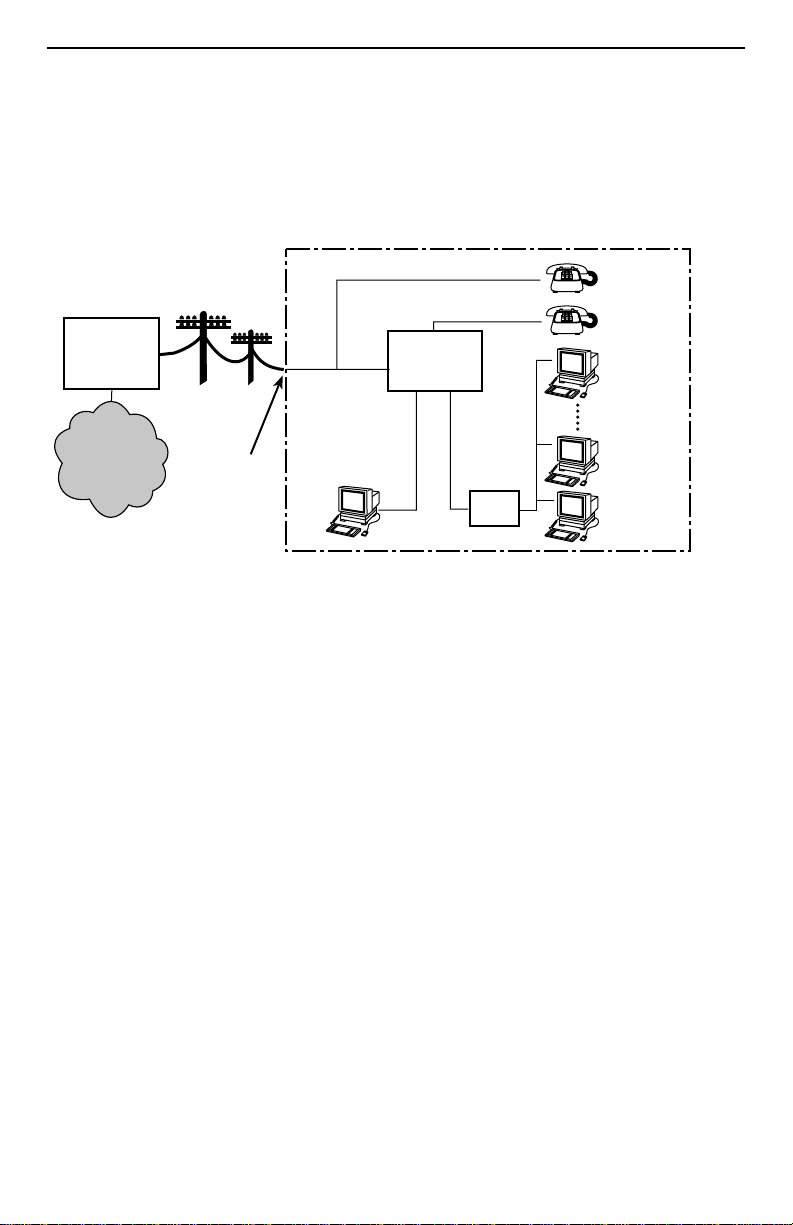
Hotwire Rea chDSL Sys t em
Copper pairs run from the central office (CO) to the customer premises (CP) to create
the local loop. The local loop terminates on the customer premises at the demarcation
point.
Customer Premises (CP)
Central
Office
(CO)
Network
Service
Provider
(NSP)
Local Loop
Demarcation
Point
DSL/POTS
Crossover
Ethernet
Cable
ReachDSL
Modem
or
Ethernet
Cable
Hub
End-user
Systems
DSL – Digital Subscriber Lines
00-16867
POTS – Plain Old Telephone Service
NOTES:
In this document:
— A telephone is used to represent any equipment that plugs into a phone jack
and uses the POTS line, such as a phone, modem, or fax machine.
— End-user system is used to repre sent an y PC with an Ethernet connect ion and
ReachDSL-based service.
— RJ11 wall jack is used to represent either an RJ11 or an RJ14 wall jack. The
RJ14 wall jack is used for a phone with two lines.
— Service provider is used to represent any Internet Service Provider (ISP) or
remote LAN access provider.
2
Page 3
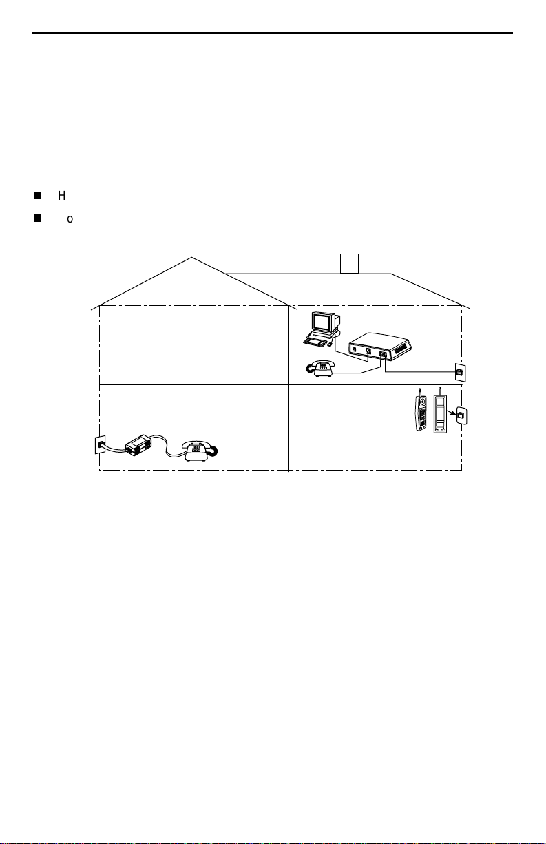
Phone Filter
Depending on the type of pho ne handset and the qual ity of the home or busi ness wiring,
a phone filter is recommended to minimize background noise during a phone
conversation. An internal phone filter is included with the Hotwire 6350 ReachDSL
Modem. If additional telephones are used on the same phone line as the ReachDSL
modem, install one phone filter on each telephone.
There are two Hotwire phone filters:
Hotwire 6035 Universal Phone Filter is designed for use with a tabletop phone.
Hotwire 6040 Wall Jack Phone Filter is designed for use with a wall phone.
Customer
Premises (CP)
ReachDSL
Modem
P
O
W
E
R
E
T
H
E
R
N
E
T
P
H
O
N
E
L
I
N
E
RJ11
Wall
Jack
6035
RJ11
Wall Jack
Phone Filter
6040
Wall Jack
Phone
Filter
01-16998
Product-Related Documents
To install a phone filter, refer to the appropriate document:
Document
Number Document Title
6035-A2-GN11
6040-A2-GN11
Contact your sales or service representative to order additional product documentation.
Paradyne documents are available on the World Wide Web at
Library → Technical Manuals → Hotwire DSL & MVL Systems.
Select
Hotwire 6035 Universal Phone Filter Installation Instructions
Hotwire 6040 MVL Wall Jack Phone Filter Installation Instructions
www.paradyne.com
.
3
Page 4

Getting Started
Before beginning your modem’s installation, make sure that you have all the equipment
that you need.
Package Checklist
Verify that your package contains the following:
Hotwire 6350 ReachDSL Modem
❑
DSL interface cable with RJ11 connectors
❑
Power cord with power transformer
❑
Be sure to register your warranty at
www.paradyne.com/warranty
.
Wiring and Cables You Need
The following standard cables and connectors are used with this product:
Standard RJ11 (or RJ14) wall jack for the DSL cabling.
❑
Standard Ethernet 8-pin, non-keyed modular plug for a PC or workstation with an
❑
Ethernet straight-through or crossover cable.
— Refer to
cable installation details.
— Refer to
assignments.
Installing the Hotwire 6350 ReachDSL Modem
Cables & Connectors
on page 11 for DSL and Ethernet cable pin
on page 5 for Ethernet
4
Page 5
Installing the Hotwire 6350 ReachDSL Modem
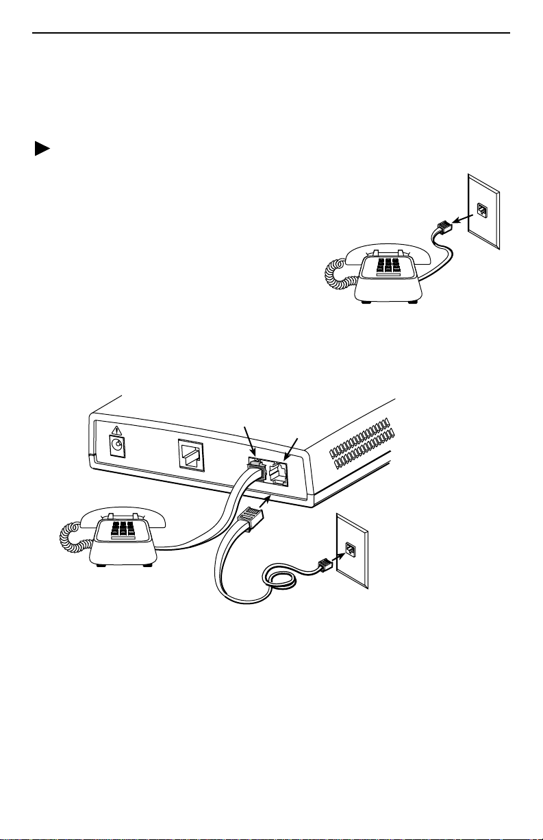
Place the Hotwire 6350 ReachDSL Modem on a flat surface with clearance for the rear
connectors.
Procedure
If a telephone is connected at the RJ11
1.
wall jack where the modem will be installed,
unplug the telephone line from the wall jack.
Connect a telephone to the modem.
2.
(Optional – go to Step3 if you are not
connecting a telephone to the ReachDSL
modem.)
Plug the existing telep hon e inte rface cable
that was unplugged in Step 1 into the jack
labeled PHONE.
Use the supplied RJ11 6-pin interface cable for the ReachDSL LINE connection.
3.
Insert one end of the cable into the jack labeled LINE. Insert the other end of the
cable into the RJ11 wall jack.
RJ11
Wall Jack
01-17015a
POW
PHONE
ER
ETHERNET
PHONE LINE
LINE
RJ11
Wall Jack
RJ11
6-pin
Interface Cable
01-17015
NOTE:
If you are installing a POTS splitter with another telephone, connect the
telephone to the jac k labele d PH ONE, then connect the jack labeled LINE to a
wall jack. Do NOT plug any cable into the POTS splitter jack labeled either
MODEM or DSL. In particular, make NO connections between a POTS splitter
and the modem.
5
Page 6
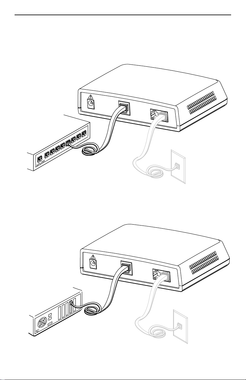
Use an 8-pin Ethernet cable f or the Ethernet connectio n. Insert one end of the cable
4.
into the jack labeled ETHERNET.
— Use a straight-through cable and connect the other end to an Ethernet hub.
(To connect to a hub’s Uplink connection, use an Ethernet crossover cable).
Ethernet
Line
POWER
ETHERNET
PHONE LINE
Ethernet
8
Hub
7
5
6
1
2
3
4
Ethernet
Straight-Through
Cable
01-17008
–or–
— Use an Ethernet crossover cable and connect the other end to a PC with an
Ethernet Network Interface Card (NIC) installed.
Ethernet
Line
POWER
PC with Ethernet
ETHERNET
PHONE LINE
Network Interface
Card
Ethernet
Crossover
Cable
01-17009
6
Page 7
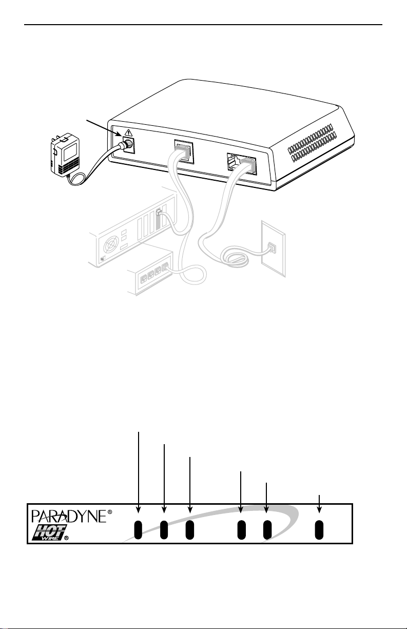
Insert the supplied power cord’s round end into the jack labeled POWER. Plug the
5.
transformer into an AC outlet.
Power
Jack
POW
ER
ETHERNET
PHONE LINE
Transformer
or
01-17010
The ReachDSL modem hardware installation is now complete. When the power cord is
installed, the ReachDS L modem goes through a power-on self-test.
Power-On
When power is applied, the ReachDSL modem performs self-diagnostics and the PWR
LED is on. The se lf-d iagnostic s in clude s a p ow er-o n sel f-test a nd al l of th e LED s turn on
for one second.
Power – green
Alarm – red
Test – yellow
DSL Line – green
Transmit/Receive – green
Ethernet Link – green
TST
ALMPWR
ReachDSL
7
LINE ETHERNET
TX/RX
01-17003
Page 8

Status LEDs
All of the LEDs turn on and off during the pow er- on self -test. Afte r a succes sful s elf-tes t,
the LEDs should appear as indicated in
LED Condition Status
in the Condition column below.
BOLD
PWR
ALM
TST
LINE
TX/RX
ETHERNET
Refer to
Troubleshooting
ON
OFF
ON
OFF
ON
ON
OFF
ON
OFF
ON
OFF
ReachDSL modem has power.
No active alarms.
An alarm condition exis ts.
No active tests.
The TST LED is on during the power-on self-test and
during a test initiated by the service provider.
The DSL link is active and ready to transmit and receive
data.
The DSL link has not been established.
Data transmission is in progress on the DSL line.
The modem is not transmitting or receiving data.
The Ethernet connection to the Ethernet hub or PC is
active.
No Ethernet 10BaseT device is detected.
on page 9 for LED indications requiring action.
8
Page 9
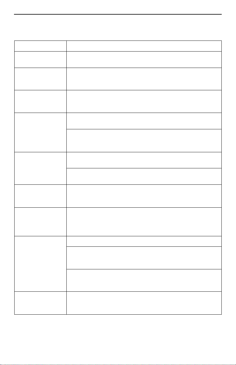
Troubleshooting
LED Symptom Action
All LEDs are on. If LEDs remain on after ten minutes, the modem is not
functional. Contact the service provider.
ALM LED remains
on.
The power-on self-test may have failed. Unplug the unit and
reapply power. If the alarm LED is still on, contact the service
provider.
ALM and TST LEDs
are blinking.
Ethernet LED is off. Verify that the Ethernet cable is securely installed at both ends,
LINE LED is off. Verify that the DSL LINE cable is securely installed on both
LINE LED is on and
there is no data
transmission.
LINE and Ethernet
LEDs are on and
there is no data
transmission.
PWR LED is off. Check that the power cord is securely installed on both ends.
Firmware downloa d ma y be in pr ogress . If f irmware do wnload is
not in progress or the LEDs con tin u e blinking after ten minutes,
contact the service provider.
and at least one PC is connected and powered on.
Verify that the correct straight-through or crossover cable is
installed. Refe r to
Modem
ends. If the problem continues, contact the service provider.
Verify that the line has dial tone. If there is no dial tone, contact
the service provider.
The DSL link has been established but there is no data
transmission. Verify the Ethernet connection. If the problem
persists, contact the service provider.
The DSL and Ethernet links have been established but there is
no data transmission. If the problem continues, contact the
service provider.
If no LEDs are on, the power supply may be defective. Test the
outlet to verify power. If the problem persists, contact the
service provider.
If other LEDs are on, the PWR LED ma y be b urned out. Unp lug
the unit and reapp ly po w er; watch all LEDs du ring the p ow er-o n
self-test to verify if the PWR LED is functioning.
on page 5.
Installing the Hotwire 6350 ReachDSL
TST LED is on. A test initiated by the service provider may be active. Wait five
minutes. If the TST LED does not go off, contact the service
provider.
9
Page 10

To improve data transmission throughput and minimize background noise during a
telephone conversation, make sure that:
The Hotwire 6350 Reac hD SL Mo dem is al w ays powered on, even when not in use,
and
A Hotwire phone filter is installed on every telephone on the same line as the
Hotwire 6350 ReachDSL Modem (see
Phone Filter
on page 3).
Increasing the Number of End-User Systems
A single end-user system is attached to the Hotwire 6350 ReachDSL Modem by using
an Ethernet crossover cable. To increase the number of end-user systems, connect all
the PCs to an Ethernet hub using a straight-through cable.
The Hotwire ReachDSL/ MVL port card supports 32 hosts/subne ts per DSL port and the
Hotwire ReachDSL Modem supports up to 256 MAC entries.
10
Page 11
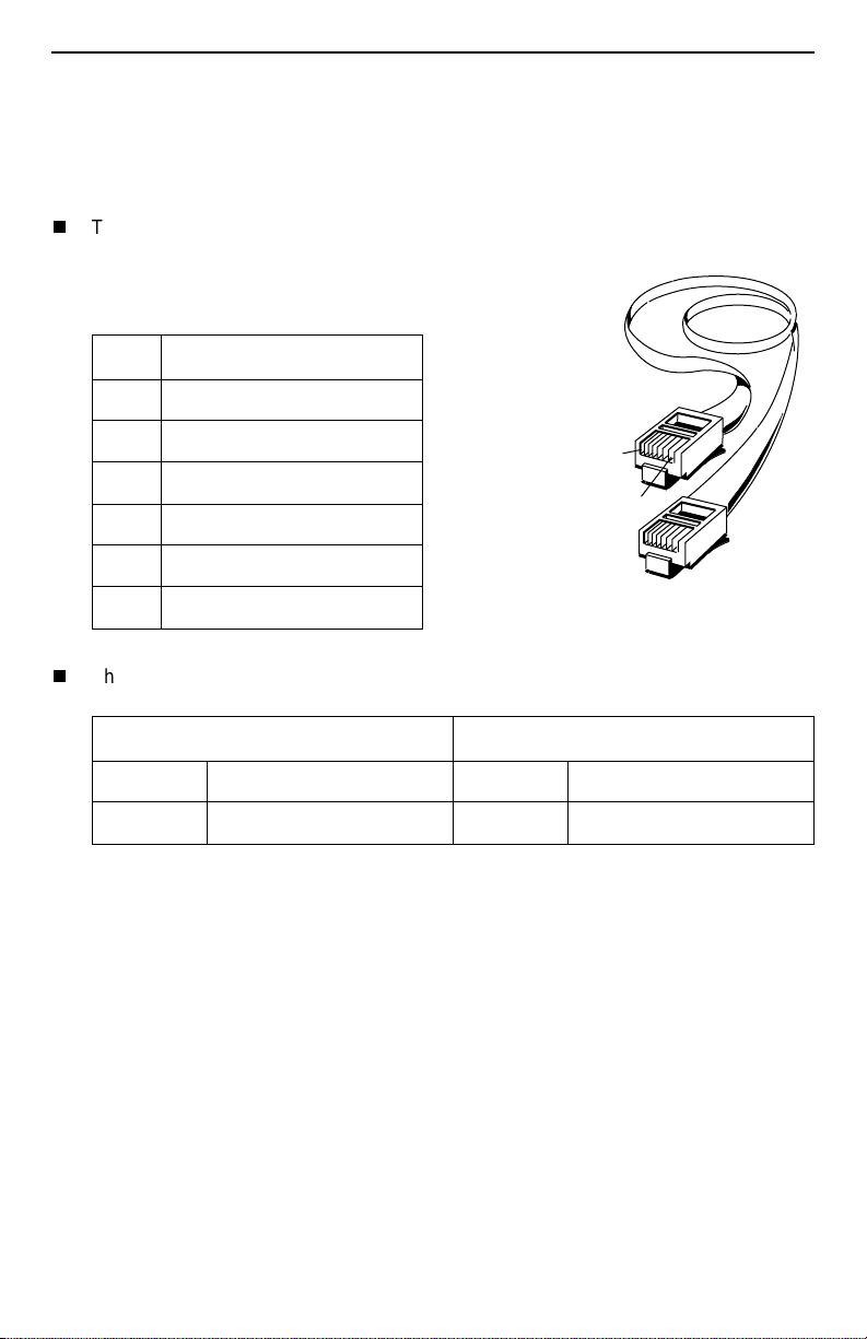
Cables & Connectors
98-15304a
6-Pin
RJ11 Plugs
Pin #1
Pin #6
This section is reference information.
Standard twisted-pair CAT3 or better cables are recommended.
The LINE and PHONE interface connectors
use 6-pin, non-ke yed modular plugs. RJ11 or
RJ14 6-pin connectors can be used.
Line & Phone Connectors
Pin # Function
1 Not used
2 Ring 2 (optional)
3 DSL Ring 1
4DSL Tip 1
5 Tip 2 (optional)
6 Not used
The LINE and PHONE jack pinouts are either filtered or unfiltered for POTS.
PHONE Jack Pinouts LINE Jack Pinouts
Pin # 3, 4 Filtered for POTS Pin # 3, 4 DSL and POTS
Pin # 2, 5 2nd POTS unfiltered Pin # 2, 5 2nd line pass-through
11
Page 12
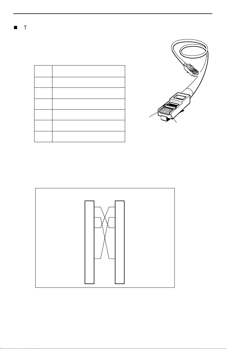
The Ethernet interface connector uses an 8-pin, non-keyed modular plug.
— To connect the DSL modem to an
Ethernet hub, use the straight-through
connection.
Ethernet
Cable
8-Pin Straight-through Connection
Pin # Function
1 10BaseT TX D+
2 10BaseT TX D–
3 10BaseT RX D+
8-Pin
Plug
4 & 5 Not used
6 10BaseT RX D–
Pin #8
Pin #1
98-16055a
7 & 8 Not used
–or–
— To connect the DSL m od em di rec tly to a PC w i th an Ethe rnet NIC c ard , u se an
Ethernet crossover cable.
8-Pin Ethernet Crossover Cable
Function Pin # FunctionPin #
10/100BaseT TX D+
10/100BaseT TX D–
10/100BaseT RX D+
Not Used
Not Used
10/100BaseT RX D–
Not Used
Not Used
1
2
3
4
5
6
7
8
1
10/100BaseT TX D+
2
10/100BaseT TX D–
3
10/100BaseT RX D+
4
Not Used
5
Not Used
6
10/100BaseT RX D–
7
Not Used
8
Not Used
Pin #1/2 = Orange/White
Twisted Pair
Pin #3/6 = Blue/White
Twisted Pair
12
99-16518
Page 13
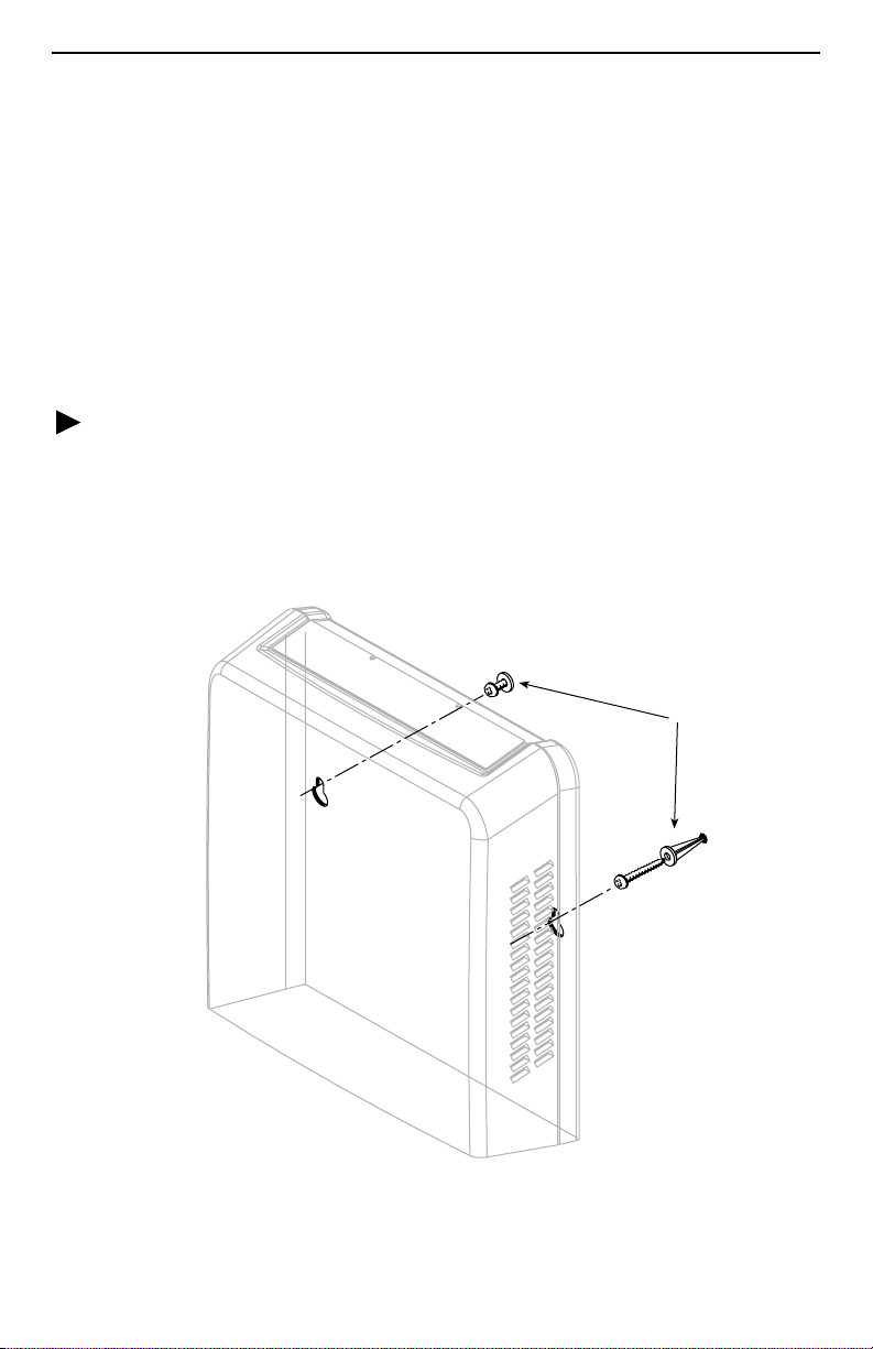
Optional ReachDSL Modem Wall Placement
The Hotwire 6350 ReachDSL Modem is designed for tabletop placement. The modem
can also be mounted on a wall. To mount the modem, you will need:
Two slotted-head #6 self-threading screws with plastic anchors
❑
Drill and 3/16" drill bit for the plastic anchors
❑
Screwdriver
❑
A template with the dimensions for the two screws is provided. See
Hardware Template
on page 14.
ReachDSL Modem
Procedure
To mount the Hotwire 6350 ReachDSL Modem:
Use a drill to install the plastic anchors.
1.
Use a screwdriv er to in sta ll the sc rews. Do not install the s crews flush with the wall.
2.
Leave enough clearance to hang the modem housing from the screws.
Wall
Fasteners
Hotwire
ReachDSL
Modem
13
01-17004
Page 14
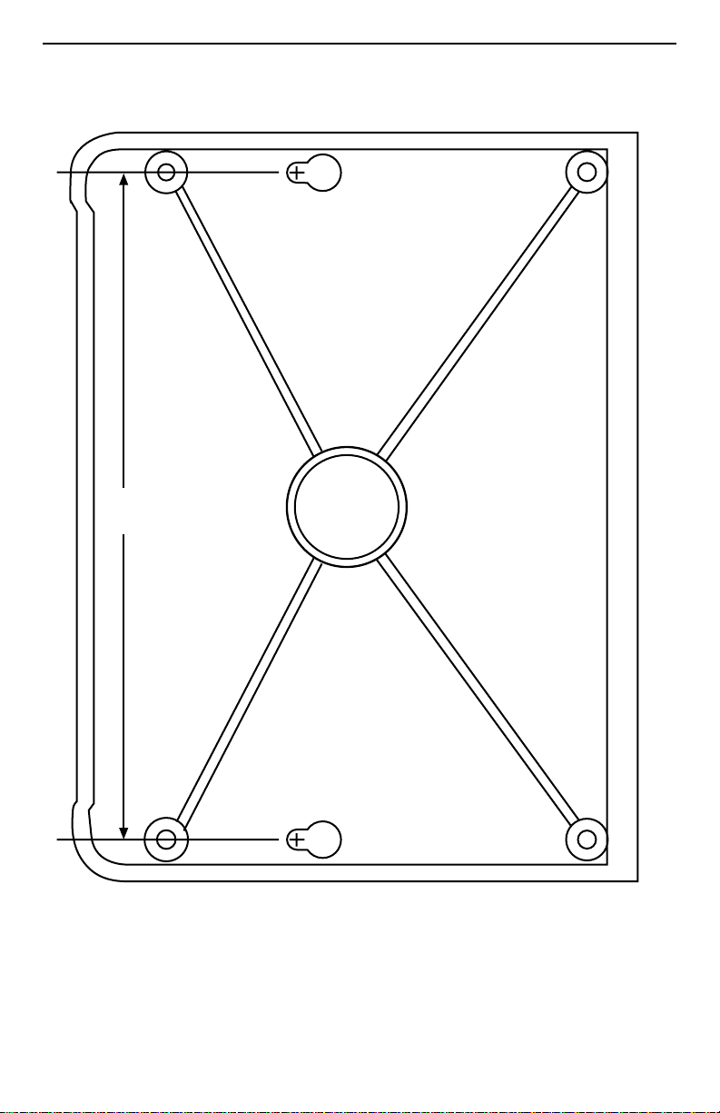
ReachDSL Modem Hardware Template
Top
5.10
Bottom
01-17014
14
Page 15
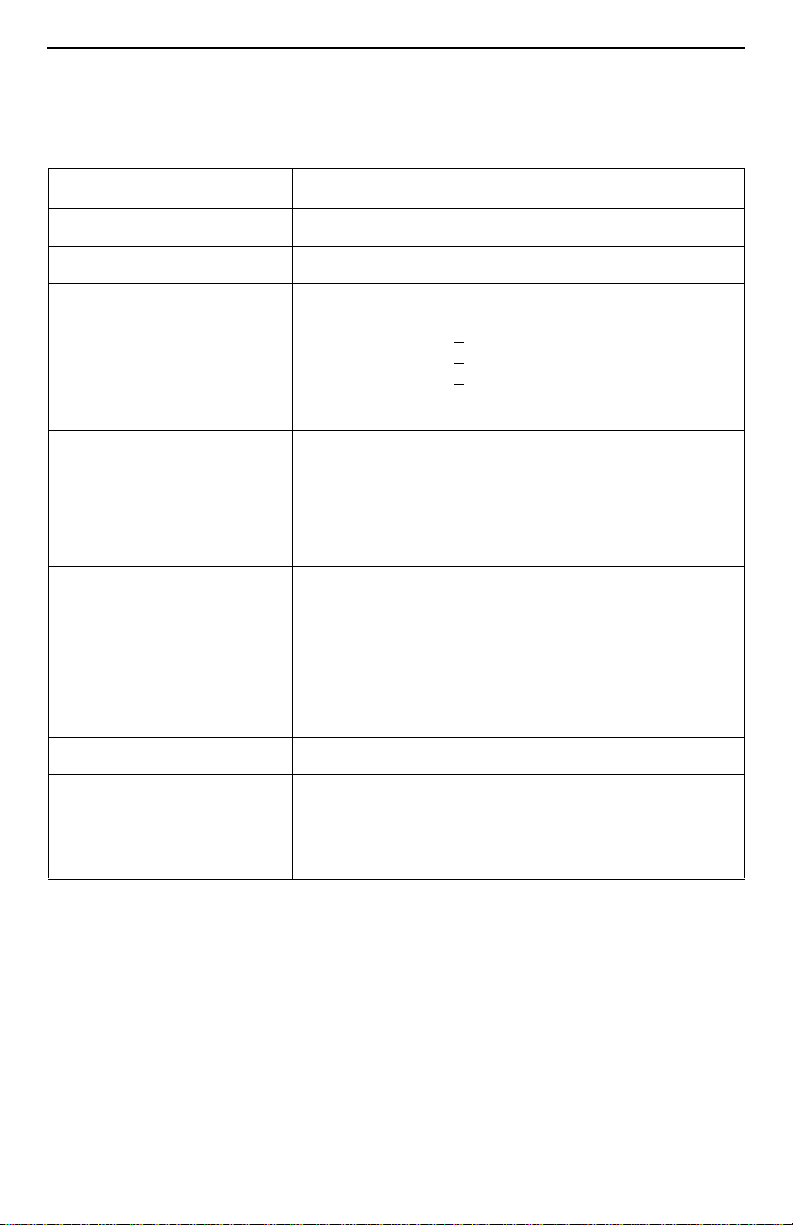
Technical Specifications for Hotwire 6350 ReachDSL Modem
Item Specification*
Height x Width x Depth
Weight
Power
Class 2 Transformer normal
service input voltage range
Approvals
FCC Part 15
CISPR 22
Other Certifications
Physical En vironment
Operating temperature
Storage temperature
Relative humidity
Shock and vibration
Heat Dissipation
Interface Connectors
Line Interface
Ethernet Type II Frame
Technical Specifications subject to change without notification.
*
1.46" x 5.72" x 4.33" (3.71 cm x 14.54 cm x 11.00 cm)
0.45 lb. (0.20 kg)
Input: 100 VAC (+
120 VAC (+10%), 60 Hz; or
230 VAC (+
Output: 5 VDC nominal, minimum 0.6A (SELV)
Class B digital device
Class B
Refer to equipment’s label for approvals on product
32°F to 104°F (0°C to 40°C)
–22°F to 158°F (–30°C to 70°C)
5% to 95% (noncondensing)
Withstands normal shipping and handling
2.35 watts at 5.0 VDC (nominal input voltage)
RJ11 or RJ14 6-pin
10BaseT 8-pin
10%), 50 Hz;
10%), 50/60 Hz
15
Page 16

!
Important Safety Instructions
Read and follow all warning notices and instructions marked on the product or
1.
included in the manual.
Slots and openings in the cabinet are provided for ventilation. To ensure reliable
2.
operation of the product and to protect it from overheating, these slots and
openings must not be blocked or covered.
Do not allow an ything to re st on th e pow er cord and d o not loca te the produc t where
3.
persons will walk on the power cord.
Do not attempt to s ervice thi s p rod uct yourself, as openi ng or re moving covers may
4.
expose you to dangerous high voltage points or other risks. Refer all servicing to
qualified service personnel.
General purpose cables are used with this product for connection to the network.
5.
Special cables , whic h ma y be requi red b y the re gulato ry inspection auth ority f or the
installation site, are the responsibility of the customer. Use a UL Listed, CSA
certified, minimum No. 24 AWG line cord for connection to the Digital Subscriber
Line (DSL) network.
When installed in the final configuration, the product must comply with the
6.
applicable Safety Standards and regulator y requirements of the country in which it
is installed. If necessary, consult with the appropriate regulatory agencies and
inspection authorities to ensure compliance.
A rare phenomenon can create a voltage potential between the earth grounds of
7.
two or more buildings. If products installed in separate buildings are
interconnected
qualified electrical consultant to determine whether or not this phenomenon exists
and, if necessary, implement corrective action prior to interconnecting the products.
Input power to this product must be provided by one of the following: (1) a UL
8.
Listed/CSA certified power source with a Class 2 or Limited Power Source (LPS)
output for use in North America, or (2) a certified transformer, with a Safety Extra
Low Voltage (SELV) ou tput having a maximum of 240 VA available, for use in the
country of installation.
In addition, since the eq uipment is to be used w ith telecommu nications ci rcuits, tak e
9.
the following precautions:
— Never install telephone wiri ng during a l ightning storm.
— Never install telephone jacks in wet locations unless the jack is specifically
designed for wet locations.
— Neve r touch uni nsulated telephon e wires o r terminals unl ess the te lephone line
has been disconnected at the network interface.
— Use caution when installing or modifying telephone lines.
— Av oid u sing a tel ephone (other th an a cordle ss ty pe) d uring an electrica l sto rm.
There may be a remote risk of electric shock from lightning.
— Do not use the telephone to report a gas leak in the vicinity of the leak.
, the voltage p oten tia l m ay cause a hazardous condit ion. Consult a
16
Page 17
CE Marking
When the product is marked with the CE mark on the equipment label, this
demonstrates full compliance with the following European Directives:
Directive 73/23/EEC
of the laws of the member states relating to electrical equipment designed for use
within states rela tin g t o electrical equipment designed for use within certain vol tage
limits, as amended by Directive 93/68/EEC.
Directive 89/336/EEC
the laws of the me mb er states relating to Electro-Magnetic Comp ati bil ity (EMC ), as
amended by Directive 93/68/EEC.
!
CANADA – EMI NOTICE:
This Class B digital apparatus meets all requirements of the Canadian
interference-causing equipment regulations.
Cet appareil numérique de la classe B respecte toutes les exigences du
règlement sur le matérial brouilleur du Canada.
– Council Directiv e of 19 F e bruary 1973 on the harmonizati on
– Council Directive of 3 May 1989 on the approximation of
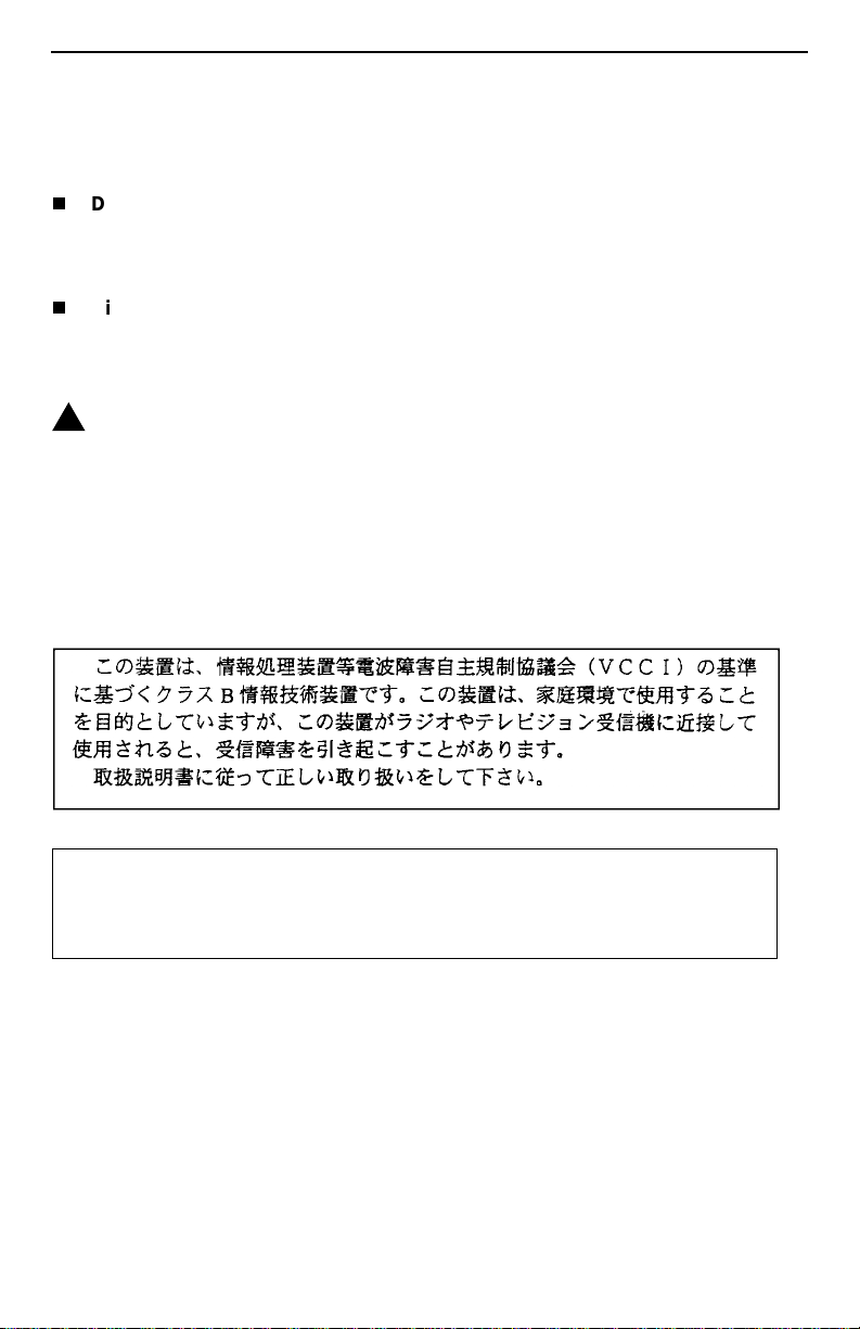
Japan – Notices
This is a Class B product based on the standard of the Voluntary Control Council for
Interference from Information Technology Equipment (VCCI). If this is used near a radio or
television receiver in a domestic environment, it may cause radio interf erence. Install and use
the equipment according to the instruction manual.
17
Page 18

Declaration of Conformity
This Declaration of Conformity is made by Paradyne Corporation pursuant to Parts 2
and 15 of the Federal Communications Commission’s Rules. This compliance
information statement pertains to the following products:
Trade Name: Hotwire
Model Number: 6350-A4-200
This devi ce complies with P art 15 of the FCC Rules . Operat ion is sub ject to the following
two conditions: (1) this device may not cause harmful interference, and (2) this device
must accept any interference received, including interferen ce that may cause undesired
operation.
The name, address, and telephone number of the responsible party is given below:
Parady ne Corpora tion
8545 126th Avenue North
Largo, FL 33773-1502
Phone: (727) 530-2000
The authority to operate this equipment is conditioned by the requirement that no
modifications will be made to the equipment unless the changes or modifications are
expressly approved by Paradyne Corporation.
This equipment ha s b een tes ted and found to comply with the limits for a Class B digital
device, pursuant to Part 15 of the FCC Rules. These limits are designed to provide
reasonable protection against harmful interference in a residential installation. This
equipment gener ates, uses, and can radiate radio frequency energy and, if not installed
and used in accordance with the instructions, may cause harmful interference to radio
communications. However, there is no guarantee that interference will not occur in a
particular installation. If this equipment does cause harmful interference to radio or
television reception, which can be determined by turning the equipment off and on, the
user is encouraged to try to correct the interference by one or more of the following
measures:
Reorient or relocate the receiving antenna.
Increase the separation between the equipment and receiver.
Connect the equipment into an outlet on a circuit different from that to which the
receiver is connected.
Consult the dealer or an experienced radio/TV technician for help.
18
Page 19

Supplier’s Declaration of Conformity
Place of Issue: Paradyne Corporation
8545 126
th
Avenue North
Largo, FL 33773-1502
USA
Date of Issue: 8/17/2001
Parady ne Corpora tion , located at the above address, hereby certifies that the Hotwire
®
ReachDSL™ Model Number 6350-A4-200, bearing labeling identification number
US:AW2DL03B6350-A4
complies with: the Federal Communications Commission’s
(“FCC”) Rules and Regulations 47 CFR P a rt 68, the Administrative Council on Terminal
Attachments (“ACTA”)-adopted technical criteria TIA/EIA/IS-96 8, “Telecommunications –
Telephone Terminal Equipment – Technical Requir ements for Connection of Terminal
Equipment To the Telephone Network, July 2001,” and TIA/EIA/IS-883,
“Telecommunications – Telephone Terminal Equipment – Supplemental Technical
Requirements f or Connecti on of Stutter Dial Tone D etection De vices an d ADSL Modems
to the Telephone Network, June 2001.”
John Koehler
Senior Vice President, DSL Products and Worldwide Services
19
Page 20

Government Requirements
Certain governments require that instructions pertaining to connection to the telephone
network be i ncluded in the installation and operation manual. Specific instructions are
listed in the following sections.
United States – Notice to Users of the Telephone Network
This equipment comp lies with P art 68 of the FCC rules . On th e equi pment is a label
1.
that contains, among other information, the FCC approval number which includes
the Ringer Equivalence Number (REN) for this equipment. The label is located on
the bottom of your modem.
The Hotwire 6350 ReachDSL Modem connects to the Public Switched Telephone
2.
Network (PSTN) using the Universal Service Order Code (USOC) RJ11C or
RJ14C.
The REN is used to determine the quantity of devices which may be connected to
3.
the telephone line. Excessive RENs on the t ele pho ne line may result in the devices
not ringing in response to an incoming ca ll. In most, b ut not al l areas, the sum of the
RENs should no t exceed five (5.0). To be certain of the number of de vi ces that may
be connected to the line, as determined by the total RENs, contact the telephone
company to determine the maximum RENs for the calling area.
If the modem causes harm to the telephone network, the telephone company will
4.
notify you in advance that temporary discontinuance of service may be required.
But if advance notice is not practical, the telephone company will notify the
customer as soon as possible. Also, you will be advised of your right to file a
complaint with the FCC if you believe it is necessary.
The telephone company may make changes in its facilities, equipment, operations,
5.
or procedures that could affect the operation of the equipment. If this happens, the
telephone company will provide advance notice in order for you to make th e
necessary modifications in order to maintain uninterrupted service.
If you experience trouble with this equipment, please contact your sales or service
6.
representative (as appropriate) for repair or warranty information. If the product
needs to be returned to th e com pan y service cent er for repair, conta ct them direc tly
for return instructions using one of the following methods:
—
Internet:
—
Telephone:
to speak with a company representative.
If the trouble is causing harm to the telephone network, the telephone company
may request that you remove the equipment from the network until the problem is
resolved.
The user is not authorized to repair or modify the equipment.
7.
Visit the Paradyne World Wide Web site at
Call our automated system to receiv e current inf ormation via f ax or
Within the U.S.A., call 1-800-870-2221
Outside the U.S.A., call 1-727-530-2340
www.paradyne.com
.
20
Page 21

This equipment cannot be used on public coin service provided by the telephone
8.
company. Connection to Party Line Service is subject to state tariffs. (Contact the
state public utility commission, public service commission or cor poration
commission for information.)
An FCC compliant telephone cord with modular plugs may be provided with this
9.
equipment. This equipment is designed to be connected to the telephone network
or premises wiring using a compatible modular jack which is Part 68 compliant.
Notice to Users of the Canadian Telephone Network
The Industry Canada label identifies certified equipment. This certification means that
the equipment meets telecommunications network protective, operational and safety
requirements as prescribed in the appropriate Terminal Equipment Technical
Requirements document(s). The Department does not guarantee the equipment will
operate to the user’s satisfaction.
Before installing this equipment, users should ensure that it is permissible to be
connected to the facilities of the local telecommunications company. The equipment
must also be installed using an acceptable method of connection. The customer should
be aware that compliance with the above conditions may not prevent degradation of
service in some situations.
Repairs to certified e qui pm ent s hou ld be c oord inated by a representative designated by
the supplier . An y repai rs or alter ations m ade b y the user to this equ ipment, o r equipmen t
malfunctions, may give the telecommunications company cause to request to
disconnect the equipment.
Users should ensure for their own protection that the electrical ground connections of
the power utility, telephone lines and internal metallic water pipe system, if present, are
connected together. This precaution may be particularly important in rural areas.
CAUTION:
Users should not attempt to make such connections themselves, but should
contact the appropriate electric inspection authority, or electrician, as
appropriate.
The Ringer Equivalence Number (REN) assigned to each terminal device provides an
indication of the maximum number of terminals allowed to be connected to a telephone
interface. The termination on an interface may consist of any combination of devices
subject only to the requirement that the sum of the Ringer Equivalence Numbers of all
the devices does not exceed 5.
If your equipment is in need of repair, refer to
Information
on page 22.
Warranty, Sales, Service, and Training
21
Page 22

Warranty, Sales, Service, and Training Information
Contact your local sales representative, service representative, or distributor directly for
any help needed. For additional information concerning warranty, sales, service, repair,
installation, documentation, training, distributor locations, or Paradyne worldwide office
locations, use one of the following methods:
Internet:
(Be sure to register your warranty at
Telephone:
speak with a company repre se nta tive.
— Within the U.S.A., call 1-800-870-2221
— Outside the U.S.A., call 1-727-530-2340
Visit the Paradyne World Wide Web site at
www.paradyne.com/warranty
Call our automated system to receive current information by fax or to
www.paradyne.com
.)
.
Document Feedback
We wel come y our co mments a nd sugge stions ab out this d ocument. Please m ail them t o
Technical Publications, Paradyne Corporation, 8545 126th Ave. N., Largo, FL 33773, or
send e-mail to
in your correspondence. Please include your name and phone number if you are willing
to provide additional clarification.
. Include the number and titl e of this document
Trademarks
Hotwire and MVL are registered trademarks of Paradyne Corporation. ReachDSL is a
trademark of Paradyne Corporation. All other products and services mentioned herein
are the trademarks, service marks, registered trademarks, or registered service marks
of their respective owners.
Patent Notification
Hotwire MVL products are protected by U.S. Patents: 4,669,090, 4,744,092, 5,291,521,
5,805,669, and 5,848,150. Other U.S. and foreign patents pending.
Copyright © 2001 Paradyne Corporation. Printed in U.S.A.
22
Page 23

Page 24

"
*6350-A2-GN12-00*
 Loading...