

Page 1

ACCULINK 3166 DSU/CSU
USER’S GUIDE
Document No. 3166-A2-GB20-10
November 1998
Page 2

Copyright 1998 Paradyne Corporation.
All rights reserved.
Printed in U.S.A.
Notice
This publication is protected by federal copyright law. No part of this publication may be copied or distributed,
transmitted, transcribed, stored in a retrieval system, or translated into any human or computer language in any form
or by any means, electronic, mechanical, magnetic, manual or otherwise, or disclosed to third parties without the
express written permission of Paradyne Corporation, 8545 126th Ave. N., Largo, FL 33773.
Paradyne Corporation makes no representation or warranties with respect to the contents hereof and specifically
disclaims any implied warranties of merchantability or fitness for a particular purpose. Further, Paradyne Corporation
reserves the right to revise this publication and to make changes from time to time in the contents hereof without
obligation of Paradyne Corporation to notify any person of such revision or changes.
Changes and enhancements to the product and to the information herein will be documented and issued as a new
release to this manual.
Warranty, Sales, and Service Information
Contact your local sales representative, service representative, or distributor directly for any help needed. For
additional information concerning warranty , sales, service, repair, installation, documentation, training, distributor
locations, or Paradyne worldwide office locations, use one of the following methods:
Via the Internet: Visit the Paradyne World Wide W eb site at http://www.paradyne.com
Via Telephone: Call our automated call system to receive current information via fax or to speak with a
company representative.
— Within the U.S.A., call 1-800-870-2221
— Outside the U.S.A., call 1-727-530-2340
Document Feedback
We welcome your comments and suggestions about this document. Please mail them to Technical Publications,
Paradyne Corporation, 8545 126th Ave. N., Largo, FL 33773, or send e-mail to [email protected]. Include
the number and title of this document in your correspondence. Please include your name and phone number if you
are willing to provide additional clarification.
Trademarks
All products and services mentioned herein are the trademarks, service marks, registered trademarks or registered
service marks of their respective owners.
Printed on recycled paper
A
November 1998
3166-A2-GB20-10
Page 3

Important Information
Important Safety Instructions
1. Read and follow all warning notices and instructions marked on the product or included in the manual.
2. Slots and openings in the cabinet are provided for ventilation. To ensure reliable operation of the product and to
protect it from overheating, these slots and openings must not be blocked or covered.
3. Do not allow anything to rest on the power cord and do not locate the product where persons will walk on the
power cord.
4. Do not attempt to service this product yourself, as opening or removing covers may expose you to dangerous
high voltage points or other risks. Refer all servicing to qualified service personnel.
5. General purpose cables are provided with this product. Special cables, which may be required by the regulatory
inspection authority for the installation site, are the responsibility of the customer.
6. When installed in the final configuration, the product must comply with the applicable Safety Standards and
regulatory requirements of the country in which it is installed. If necessary , consult with the appropriate regulatory
agencies and inspection authorities to ensure compliance.
7. A rare phenomenon can create a voltage potential between the earth grounds of two or more buildings. If
products installed in separate buildings are interconnected, the voltage potential may cause a hazardous
condition. Consult a qualified electrical consultant to determine whether or not this phenomenon exists and, if
necessary, implement corrective action prior to interconnecting the products.
8. Input power to the ac voltage configuration of this product must be provided by a UL-listed or CSA-certified power
source with a Class 2 or Limited Power Source (LPS) output. Input power to the dc voltage configurations of this
product must be provided by a National Electric Code (NEC) or a Canadian Electric Code (CEC) Class 2 circuit.
9. This product contains a coin cell lithium battery that is only to be replaced at the factory . Caution: There is a
danger of explosion if the battery is incorrectly replaced. Replace only with the same type. Dispose of used
batteries according to the battery manufacturer’s instructions. Attention: Il y a danger d’explosion s’il y a
remplacement incorrect de la batterie. Remplacer uniquement avec une batterie du même type. Mettre au rebut
les batteries usagées conformément aux instructions du fabricant.
10. In addition, if the equipment is to be used with telecommunications circuits, take the following precautions:
— Never install telephone wiring during a lightning storm.
— Never install telephone jacks in wet locations unless the jack is specifically designed for wet locations.
— Never touch uninsulated telephone wires or terminals unless the telephone line has been disconnected at the
network interface.
— Use caution when installing or modifying telephone lines.
— Avoid using a telephone (other than a cordless type) during an electrical storm. There may be a remote risk of
electric shock from lightning.
— Do not use the telephone to report a gas leak in the vicinity of the leak.
3166-A2-GB20-10 November 1998
B
Page 4

Important Information
EMI Warnings
!
WARNING:
This equipment has been tested and found to comply with the limits for a Class A digital device,
pursuant to Part 15 of the FCC rules. These limits are designed to provide reasonable protection against
harmful interference when the equipment is operated in a commercial environment. This equipment
generates, uses, and can radiate radio frequency energy and, if not installed and used in accordance
with the instruction manual, may cause harmful interference to radio communications. Operation of this
equipment in a residential area is likely to cause harmful interference in which case the user will be
required to correct the interference at his own expense.
The authority to operate this equipment is conditioned by the requirements that no modifications will be
made to the equipment unless the changes or modifications are expressly approved by Paradyne
Corporation.
!
WARNING:
To Users of Digital Apparatus in Canada:
This Class A digital apparatus meets all requirements of the Canadian interference-causing equipment
regulations.
Cet appareil numérique de la classe A respecte toutes les exigences du règlement sur le matérial
brouilleur du Canada.
C
November 1998
3166-A2-GB20-10
Page 5

Important Information
Government Requirements and Equipment Return
Certain governments require that instructions pertaining to CSU connection to the telephone network be included in
the installation and operation manual. Specific instructions are listed in the following sections.
United States
NOTICE TO USERS OF THE UNITED STATES TELEPHONE NETWORK
1. This equipment complies with Part 68 of the FCC rules. On the equipment is a label that contains, among other
information, the FCC registration number for this equipment. The label is on the 3166 DSU/CSU’s circuit card. If
requested, this information must be provided to the telephone company .
2. The T1 network connection should be made using a Universal Service Order Code (USOC) type RJ48C jack. The
Service Order Code 6.0F should be specified to the telephone company when ordering the T1 line. In addition,
the proper Facility Interface Code must be specified to the Telephone Company. The DSU/CSU can be configured
to support any of the following framing format and line signaling techniques. The DSU/CSU’s configuration must
correspond to the T1 line’s parameters.
3166 DSU/CSU Facility Interface Codes
Code
04DU9-BN 1.544 Mbps superframe format (SF) without line power
04DU9-DN 1.544 Mbps SF and B8ZS without line power
04DU9-1KN 1.544 Mbps ANSI ESF without line power
04DU-1SN 1.544 Mbps ANSI ESF and B8ZS without line power
3. If the 3166 DSU/CSU causes harm to the telephone network, the telephone company will notify you in advance
that temporary discontinuance of service may be required. But if advance notice is not practical, the telephone
company will notify the customer as soon as possible. Also, you will be advised of your right to file a complaint
with the FCC if you believe it is necessary.
4. The telephone company may make changes in its facilities, equipment, operations, or procedures that could affect
the operation of the equipment. If this happens, the telephone company will provide advance notice in order for
you to make the necessary modifications in order to maintain uninterrupted service.
5. If you experience trouble with this equipment, please contact your sales or service representative (as appropriate)
for repair or warranty information. If the product needs to be returned to the company service center for repair,
contact them directly for return instructions using one of the following methods:
Via the Internet: Visit the Paradyne World Wide W eb site at http://www.paradyne.com
Via Telephone: Call our automated call system to receive current information via fax or to speak with a
company representative.
— Within the U.S.A., call 1-800-870-2221
— Outside the U.S.A., call 1-727-530-2340
If the trouble is causing harm to the telephone network, the telephone company may request that you remove the
equipment from the network until the problem is resolved.
Description
6. FCC compliant telephone line cords with modular plugs are provided with this equipment. This equipment is
designed to be connected to the telephone network or premises wiring using a compatible modular jack which is
Part 68 compliant.
3166-A2-GB20-10 November 1998
D
Page 6

Important Information
Canada
NOTICE TO USERS OF THE CANADIAN TELEPHONE NETWORK
The Industry Canada label identifies certified equipment. This certification means that the equipment meets
telecommunications network protective, operational and safety requirements as prescribed in the appropriate Terminal
Equipment Technical Requirements document(s). The Department does not guarantee the equipment will operate to
the user’s satisfaction.
Before installing this equipment, users should ensure that it is permissible to be connected to the facilities of the local
telecommunications company. The equipment must also be installed using an acceptable method of connection. The
customer should be aware that compliance with the above conditions may not prevent degradation of service in some
situations.
Repairs to certified equipment should be coordinated by a representative designated by the supplier. Any repairs or
alterations made by the user to this equipment, or equipment malfunctions, may give the telecommunications
company cause to request to disconnect the equipment.
Users should ensure for their own protection that the electrical ground connections of the power utility , telephone lines
and internal metallic water pipe system, if present, are connected together. This precaution may be particularly
important in rural areas.
CAUTION:
Users should not attempt to make such connections themselves, but should contact the appropriate
electric inspection authority , or electrician, as appropriate.
The Ringer Equivalence Number (REN) assigned to each terminal device provides an indication of the maximum
number of terminals allowed to be connected to a telephone interface. The termination on an interface may consist of
any combination of devices subject only to the requirement that the sum of the Ringer Equivalence Numbers of all the
devices does not exceed 5.
If your equipment is in need of repair, refer to
Warranty, Sales, and Service Information
on page A.
E
November 1998
3166-A2-GB20-10
Page 7

Contents
About This Guide
Document Purpose and Intended Audience vii. . . . . . . . . . . . . . . . . . . . . . . . .
Document Summary vii. . . . . . . . . . . . . . . . . . . . . . . . . . . . . . . . . . . . . . . . . . . . .
Product-Related Documents viii. . . . . . . . . . . . . . . . . . . . . . . . . . . . . . . . . . . . . .
Reference Documents ix. . . . . . . . . . . . . . . . . . . . . . . . . . . . . . . . . . . . . . . . . . .
1 Introduction
Overview 1-1. . . . . . . . . . . . . . . . . . . . . . . . . . . . . . . . . . . . . . . . . . . . . . . . . . . . . .
Features 1-1. . . . . . . . . . . . . . . . . . . . . . . . . . . . . . . . . . . . . . . . . . . . . . . . . . . . . . .
Physical Description 1-3. . . . . . . . . . . . . . . . . . . . . . . . . . . . . . . . . . . . . . . . . . . . .
Alarm Message Capability 1-2. . . . . . . . . . . . . . . . . . . . . . . . . . . . . . . . . . . .
Front Panel Emulation 1-2. . . . . . . . . . . . . . . . . . . . . . . . . . . . . . . . . . . . . . .
Asynchronous Terminal Interface (ATI) Support 1-2. . . . . . . . . . . . . . . . . .
Telnet Access 1-2. . . . . . . . . . . . . . . . . . . . . . . . . . . . . . . . . . . . . . . . . . . . . . .
SNMP Management Support 1-2. . . . . . . . . . . . . . . . . . . . . . . . . . . . . . . . . .
2 Installation
Important Instructions 2-1. . . . . . . . . . . . . . . . . . . . . . . . . . . . . . . . . . . . . . . . . . . .
Installation 2-2. . . . . . . . . . . . . . . . . . . . . . . . . . . . . . . . . . . . . . . . . . . . . . . . . . . . .
3166-A2-GB20-10
November 1998
i
Page 8

Contents
3 SDCP Operation
Overview 3-1. . . . . . . . . . . . . . . . . . . . . . . . . . . . . . . . . . . . . . . . . . . . . . . . . . . . . .
Using the SDCP 3-1. . . . . . . . . . . . . . . . . . . . . . . . . . . . . . . . . . . . . . . . . . . . . . . .
Displaying Unit Identity 3-7. . . . . . . . . . . . . . . . . . . . . . . . . . . . . . . . . . . . . . . . . .
Setting Customer Identification 3-9. . . . . . . . . . . . . . . . . . . . . . . . . . . . . . . . . . . .
Displaying LED Conditions 3-10. . . . . . . . . . . . . . . . . . . . . . . . . . . . . . . . . . . . . . .
Changing Configuration Options 3-1 1. . . . . . . . . . . . . . . . . . . . . . . . . . . . . . . . . .
Enabling the Communication Port 3-16. . . . . . . . . . . . . . . . . . . . . . . . . . . . . . . . .
Configuring the DSU/CSU for SNMP or Telnet Access 3-19. . . . . . . . . . . . . . .
Configuring SNMP Traps 3-26. . . . . . . . . . . . . . . . . . . . . . . . . . . . . . . . . . . . . . . . .
Selecting the Timing Source 3-34. . . . . . . . . . . . . . . . . . . . . . . . . . . . . . . . . . . . . .
Establishing Access Security on the COM Port 3-35. . . . . . . . . . . . . . . . . . . . . .
Setting a Password 3-36. . . . . . . . . . . . . . . . . . . . . . . . . . . . . . . . . . . . . . . . . . . . . .
Entering a Password to Gain Access 3-37. . . . . . . . . . . . . . . . . . . . . . . . . . . . . .
Acquiring/Releasing the User Interface 3-38. . . . . . . . . . . . . . . . . . . . . . . . . . . . .
Resetting the DSU/CSU 3-40. . . . . . . . . . . . . . . . . . . . . . . . . . . . . . . . . . . . . . . . .
LCD 3-2. . . . . . . . . . . . . . . . . . . . . . . . . . . . . . . . . . . . . . . . . . . . . . . . . . . . . . .
Keypad 3-2. . . . . . . . . . . . . . . . . . . . . . . . . . . . . . . . . . . . . . . . . . . . . . . . . . . .
Test Jacks 3-3. . . . . . . . . . . . . . . . . . . . . . . . . . . . . . . . . . . . . . . . . . . . . . . . . .
LEDs 3-4. . . . . . . . . . . . . . . . . . . . . . . . . . . . . . . . . . . . . . . . . . . . . . . . . . . . . .
Displaying/Editing Configuration Options 3-13. . . . . . . . . . . . . . . . . . . . . . .
Saving Edit Changes 3-15. . . . . . . . . . . . . . . . . . . . . . . . . . . . . . . . . . . . . . . . .
Selecting the Port 3-20. . . . . . . . . . . . . . . . . . . . . . . . . . . . . . . . . . . . . . . . . . .
Setting the IP Address 3-21. . . . . . . . . . . . . . . . . . . . . . . . . . . . . . . . . . . . . . .
Selecting the Link Layer Protocol 3-23. . . . . . . . . . . . . . . . . . . . . . . . . . . . . .
Specifying the Community Name(s) and Access Type(s) 3-24. . . . . . . . . .
Enabling SNMP Trap Messages 3-26. . . . . . . . . . . . . . . . . . . . . . . . . . . . . . .
Selecting the Number of Trap Managers 3-27. . . . . . . . . . . . . . . . . . . . . . . .
Configuring a Destination for SNMP Traps 3-28. . . . . . . . . . . . . . . . . . . . . .
Allocating Data Ports 3-29. . . . . . . . . . . . . . . . . . . . . . . . . . . . . . . . . . . . . . . . .
Block or ACAMI Assignment Method 3-31. . . . . . . . . . . . . . . . . . . . . . . . . . .
Individual Channel Assignment Method 3-32. . . . . . . . . . . . . . . . . . . . . . . .
Clearing DS0 Channel Allocation 3-33. . . . . . . . . . . . . . . . . . . . . . . . . . . . . .
Configuring for Network Timing 3-34. . . . . . . . . . . . . . . . . . . . . . . . . . . . . . . .
Acquiring the Active User Interface 3-38. . . . . . . . . . . . . . . . . . . . . . . . . . . .
Releasing the Active User Interface 3-39. . . . . . . . . . . . . . . . . . . . . . . . . . . .
ii
November 1998
3166-A2-GB20-10
Page 9

4 Monitoring and Testing
Overview 4-1. . . . . . . . . . . . . . . . . . . . . . . . . . . . . . . . . . . . . . . . . . . . . . . . . . . . . .
Self-Test Health 4-1. . . . . . . . . . . . . . . . . . . . . . . . . . . . . . . . . . . . . . . . . . . . . . . . .
Device Health and Status 4-3. . . . . . . . . . . . . . . . . . . . . . . . . . . . . . . . . . . . . . . .
Performance Reports 4-5. . . . . . . . . . . . . . . . . . . . . . . . . . . . . . . . . . . . . . . . . . . .
Resetting Performance Registers 4-10. . . . . . . . . . . . . . . . . . . . . . . . . . . . . .
Alarms 4-11. . . . . . . . . . . . . . . . . . . . . . . . . . . . . . . . . . . . . . . . . . . . . . . . . . . . . . . . .
SNMP Traps 4-12. . . . . . . . . . . . . . . . . . . . . . . . . . . . . . . . . . . . . . . . . . . . . . . . . . .
Troubleshooting 4-14. . . . . . . . . . . . . . . . . . . . . . . . . . . . . . . . . . . . . . . . . . . . . . . . .
Test Jacks 4-15. . . . . . . . . . . . . . . . . . . . . . . . . . . . . . . . . . . . . . . . . . . . . . . . . . . . .
Test Commands 4-15. . . . . . . . . . . . . . . . . . . . . . . . . . . . . . . . . . . . . . . . . . . . . . . .
Remote Loopback Tests 4-16. . . . . . . . . . . . . . . . . . . . . . . . . . . . . . . . . . . . . . . . .
Sending a Line Loopback Up or Down 4-17. . . . . . . . . . . . . . . . . . . . . . . . .
Sending a V.54/ANSI FT1 Activation/Deactivation 4-18. . . . . . . . . . . . . . . .
Local Loopback Tests 4-19. . . . . . . . . . . . . . . . . . . . . . . . . . . . . . . . . . . . . . . . . . . .
Starting a Line Loopback 4-20. . . . . . . . . . . . . . . . . . . . . . . . . . . . . . . . . . . . .
Starting a Payload Loopback 4-21. . . . . . . . . . . . . . . . . . . . . . . . . . . . . . . . . .
Starting a Repeater Loopback 4-22. . . . . . . . . . . . . . . . . . . . . . . . . . . . . . . . .
Starting a Data Channel Loopback 4-23. . . . . . . . . . . . . . . . . . . . . . . . . . . . .
Starting a Data Terminal Loopback 4-24. . . . . . . . . . . . . . . . . . . . . . . . . . . .
Aborting Loopbacks 4-25. . . . . . . . . . . . . . . . . . . . . . . . . . . . . . . . . . . . . . . . . .
Test Patterns 4-26. . . . . . . . . . . . . . . . . . . . . . . . . . . . . . . . . . . . . . . . . . . . . . . . . . .
Sending Test Patterns 4-26. . . . . . . . . . . . . . . . . . . . . . . . . . . . . . . . . . . . . . . .
Monitoring Test Patterns 4-27. . . . . . . . . . . . . . . . . . . . . . . . . . . . . . . . . . . . . .
Aborting Test Patterns 4-28. . . . . . . . . . . . . . . . . . . . . . . . . . . . . . . . . . . . . . . .
Lamp Test 4-30. . . . . . . . . . . . . . . . . . . . . . . . . . . . . . . . . . . . . . . . . . . . . . . . . . . . . .
Starting a Lamp Test 4-30. . . . . . . . . . . . . . . . . . . . . . . . . . . . . . . . . . . . . . . . .
Aborting a Lamp Test 4-31. . . . . . . . . . . . . . . . . . . . . . . . . . . . . . . . . . . . . . . .
Displaying DSU/CSU Test Status 4-32. . . . . . . . . . . . . . . . . . . . . . . . . . . . . . . . . .
Contents
3166-A2-GB20-10
November 1998
iii
Page 10

Contents
A SDCP Menu
B Technical Specifications
Overview B-1. . . . . . . . . . . . . . . . . . . . . . . . . . . . . . . . . . . . . . . . . . . . . . . . . . . . . .
C Configuration Options
Overview C-1. . . . . . . . . . . . . . . . . . . . . . . . . . . . . . . . . . . . . . . . . . . . . . . . . . . . . .
Port Configuration Options C-2. . . . . . . . . . . . . . . . . . . . . . . . . . . . . . . . . . . . . . .
Network Interface Configuration Options C-7. . . . . . . . . . . . . . . . . . . . . . . . . . .
General Configuration Options C-9. . . . . . . . . . . . . . . . . . . . . . . . . . . . . . . . . . . .
User Interface Configuration Options C-10. . . . . . . . . . . . . . . . . . . . . . . . . . . . . .
Alarm Configuration Options C-16. . . . . . . . . . . . . . . . . . . . . . . . . . . . . . . . . . . . . .
Management Configuration Options C-19. . . . . . . . . . . . . . . . . . . . . . . . . . . . . . .
D Pin Assignments
Overview D-1. . . . . . . . . . . . . . . . . . . . . . . . . . . . . . . . . . . . . . . . . . . . . . . . . . . . . .
T1 Network Interface D-1. . . . . . . . . . . . . . . . . . . . . . . . . . . . . . . . . . . . . . . . . . . .
EIA-530-A Port Interface Connector D-3. . . . . . . . . . . . . . . . . . . . . . . . . . . . . . .
EIA-530-A-to-RS449 Cable Interface D-4. . . . . . . . . . . . . . . . . . . . . . . . . . . . . .
EIA-530-A-to-V.35 Cable Interface D-6. . . . . . . . . . . . . . . . . . . . . . . . . . . . . . . .
EIA-530-A-to-X.21 Cable Interface D-8. . . . . . . . . . . . . . . . . . . . . . . . . . . . . . . .
COM Port Interface D-9. . . . . . . . . . . . . . . . . . . . . . . . . . . . . . . . . . . . . . . . . . . . . .
COM Port to Modem Cable D-11. . . . . . . . . . . . . . . . . . . . . . . . . . . . . . . . . . . . . . .
iv
November 1998
3166-A2-GB20-10
Page 11

E SNMP MIB Objects
Overview E-1. . . . . . . . . . . . . . . . . . . . . . . . . . . . . . . . . . . . . . . . . . . . . . . . . . . . . .
MIB II (RFC 1213) E-2. . . . . . . . . . . . . . . . . . . . . . . . . . . . . . . . . . . . . . . . . . . . . . .
System Group, MIB II E-2. . . . . . . . . . . . . . . . . . . . . . . . . . . . . . . . . . . . . . . .
Interface Group, MIB II E-3. . . . . . . . . . . . . . . . . . . . . . . . . . . . . . . . . . . . . . .
IP Group, MIB II E-6. . . . . . . . . . . . . . . . . . . . . . . . . . . . . . . . . . . . . . . . . . . . .
ICMP Group, MIB II E-9. . . . . . . . . . . . . . . . . . . . . . . . . . . . . . . . . . . . . . . . . .
TCP Group, MIB II E-9. . . . . . . . . . . . . . . . . . . . . . . . . . . . . . . . . . . . . . . . . . .
UDP Group, MIB II E-9. . . . . . . . . . . . . . . . . . . . . . . . . . . . . . . . . . . . . . . . . . .
Transmission Group, MIB II E-10. . . . . . . . . . . . . . . . . . . . . . . . . . . . . . . . . . .
SNMP Group, MIB II E-10. . . . . . . . . . . . . . . . . . . . . . . . . . . . . . . . . . . . . . . . .
DS1/E1 MIB (RFC 1406) E-10. . . . . . . . . . . . . . . . . . . . . . . . . . . . . . . . . . . . . . . . .
Near End Group, DS1/E1 MIB E-11. . . . . . . . . . . . . . . . . . . . . . . . . . . . . . . . .
Far End Group, DS1/E1 MIB E-14. . . . . . . . . . . . . . . . . . . . . . . . . . . . . . . . . .
DS1 Fractional Group, DS1/E1 MIB E-15. . . . . . . . . . . . . . . . . . . . . . . . . . . .
RS-232-like MIB (RFC 1317) E-15. . . . . . . . . . . . . . . . . . . . . . . . . . . . . . . . . . . . .
General Port Table, RS-232-like MIB E-15. . . . . . . . . . . . . . . . . . . . . . . . . . .
Asynchronous Port Table, RS-232-like MIB E-16. . . . . . . . . . . . . . . . . . . . .
Synchronous Port Table, RS-232-like MIB E-17. . . . . . . . . . . . . . . . . . . . . .
Input Signal Table, RS-232-like MIB E-18. . . . . . . . . . . . . . . . . . . . . . . . . . . .
Output Signal Table, RS-232-like MIB E-18. . . . . . . . . . . . . . . . . . . . . . . . . .
Generic-Interface MIB Extensions (RFC 1229) E-19. . . . . . . . . . . . . . . . . . . . . .
Generic Interface Test Table, Generic Interface MIB E-19. . . . . . . . . . . . . .
Enterprise MIB E-21. . . . . . . . . . . . . . . . . . . . . . . . . . . . . . . . . . . . . . . . . . . . . . . . . .
Correlation between Menu Commands and SNMP Objects E-22. . . . . . . . . . .
Contents
F IP Networking Address Scenario
Overview F-1. . . . . . . . . . . . . . . . . . . . . . . . . . . . . . . . . . . . . . . . . . . . . . . . . . . . . .
Scenario 1 F-2. . . . . . . . . . . . . . . . . . . . . . . . . . . . . . . . . . . . . . . . . . . . . . . . . . . . .
Scenario 2 F-3. . . . . . . . . . . . . . . . . . . . . . . . . . . . . . . . . . . . . . . . . . . . . . . . . . . . .
Scenario 3 F-4. . . . . . . . . . . . . . . . . . . . . . . . . . . . . . . . . . . . . . . . . . . . . . . . . . . . .
Scenario 4 F-5. . . . . . . . . . . . . . . . . . . . . . . . . . . . . . . . . . . . . . . . . . . . . . . . . . . . .
Scenario 5 F-6. . . . . . . . . . . . . . . . . . . . . . . . . . . . . . . . . . . . . . . . . . . . . . . . . . . . .
3166-A2-GB20-10
November 1998
v
Page 12

Contents
G Front Panel Emulation
Overview G-1. . . . . . . . . . . . . . . . . . . . . . . . . . . . . . . . . . . . . . . . . . . . . . . . . . . . . .
Installing Front Panel Emulation Software G-1. . . . . . . . . . . . . . . . . . . . . . . . . .
Starting Front Panel Emulation G-3. . . . . . . . . . . . . . . . . . . . . . . . . . . . . . . . . . . .
H Asynchronous Terminal Interface Operation
Overview H-1. . . . . . . . . . . . . . . . . . . . . . . . . . . . . . . . . . . . . . . . . . . . . . . . . . . . . .
Before Using the ATI H-1. . . . . . . . . . . . . . . . . . . . . . . . . . . . . . . . . . . . . . . . . . . .
Resetting the ATI H-1. . . . . . . . . . . . . . . . . . . . . . . . . . . . . . . . . . . . . . . . . . . . . . .
Initiating an ATI Session H-2. . . . . . . . . . . . . . . . . . . . . . . . . . . . . . . . . . . . . . . . .
Ending an ATI Session H-2. . . . . . . . . . . . . . . . . . . . . . . . . . . . . . . . . . . . . . . . . . .
Menu Organization H-3. . . . . . . . . . . . . . . . . . . . . . . . . . . . . . . . . . . . . . . . . . . . . .
Using ATI Screens H-4. . . . . . . . . . . . . . . . . . . . . . . . . . . . . . . . . . . . . . . . . . . . . .
Setting Customer Identification H-6. . . . . . . . . . . . . . . . . . . . . . . . . . . . . . . . . . . .
Displaying LED Conditions H-7. . . . . . . . . . . . . . . . . . . . . . . . . . . . . . . . . . . . . . .
Changing Configuration Options H-8. . . . . . . . . . . . . . . . . . . . . . . . . . . . . . . . . .
Displaying or Editing Configuration Options H-8. . . . . . . . . . . . . . . . . . . . .
Saving Edit Changes H-10. . . . . . . . . . . . . . . . . . . . . . . . . . . . . . . . . . . . . . . . .
Establishing Access Security on a Port H-11. . . . . . . . . . . . . . . . . . . . . . . . . . . . .
Setting a Password H-12. . . . . . . . . . . . . . . . . . . . . . . . . . . . . . . . . . . . . . . . . . . . . .
Entering a Password to Gain Access H-13. . . . . . . . . . . . . . . . . . . . . . . . . . . . . .
I Equipment List
Glossary
Index
vi
November 1998
3166-A2-GB20-10
Page 13

About This Guide
Document Purpose and Intended Audience
This operator’s guide contains installation, operation, and maintenance
information for the ACCULINK 3166 Data Service Unit (DSU)/Channel Service
Unit (CSU).
It is assumed that you are familiar with the operation of digital data
communication equipment. You should also be familiar with Simple Network
Management Protocol (SNMP) if you want your DSU/CSU to be managed by an
SNMP manager.
Document Summary
Section Description
Chapter 1
Chapter 2
Chapter 3
Chapter 4
Appendix A
Appendix B
Appendix C
Appendix D
Introduction.
Installation.
SDCP Operation.
Diagnostic Control Panel (SDCP), including using the SDCP
to configure SNMP parameters and security.
Monitoring and Testing.
about the status and performance of the DSU/CSU, how to
troubleshoot problems, and how to run tests.
SDCP Menu.
branches of the Shared Diagnostic Control Panel (SDCP)
interface.
Technical Specifications
specifications of the DSU/CSU.
Configuration Options.
options.
Pin Assignments.
connectors used with the DSU/CSU.
Describes the features of the DSU/CSU.
Explains how to install the DSU/CSU.
Explains the use of the optional Shared
Explains how to obtain information
Contains a menu tree showing the main
. Contains a table with the
Lists and explains the configuration
Describes the pin assignments for
3166-A2-GB20-10
November 1998
vii
Page 14

About This Guide
Section Description
Appendix E
Appendix F
Appendix G
Appendix H
Appendix I
Glossary Explains terms and abbreviations used in the text.
Index Lists major topics in the text.
Product-Related Documents
Document Number Document Title
3000-A2-GA31
SNMP MIB Objects.
provided by the DSU/CSU.
IP Network Addressing Scenarios.
addressing in sample networks.
Front Panel Emulation.
panel emulation software.
Asynchronous Terminal Interface Operation.
function and use of the Asynchronous Terminal Interface (ATI).
Equipment List.
the DSU/CSU.
COMSPHERE 3000 Series Carrier Installation
Manual
Lists and describes the MIB support
Shows the use of IP
Explains the use of the optional front
Describes the
Lists feature numbers for equipment related to
3000-A2-GB41
Contact your sales or service representative to order additional product
documentation.
Paradyne documents are also available on the World Wide Web at:
http://www.paradyne.com
Select
Service & Support → Technical Manuals
COMSPHERE –48 VDC Central Office Power Unit
Installation Guide
viii
November 1998
3166-A2-GB20-10
Page 15

Reference Documents
AT&T Technical Reference 54016
AT&T Technical Reference 62411
ANSI T1.403-1989
Industry Canada CS-03
CSA-22.2 No. 950
Industry Canada (ICES)-003
FCC Part 15
FCC Part 68
UL 1950
Management Information Base for Network Management of TCP/IP-Based
Internets:
Definitions of Managed Objects for the DS1 and E1 Interface Types
RFC 1406, January 1993
MIBII
. RFC 1213, March 1991
About This Guide
.
Definitions of Managed Objects for RS-232-like Hardware Devices
RFC 1317, April 1992
Extensions to the Generic-Interface MIB
. RFC 1229, May 1991
.
3166-A2-GB20-10
November 1998
ix
Page 16

About This Guide
This page intentionally left blank.
x
November 1998
3166-A2-GB20-10
Page 17

Introduction
Overview
1
The ACCULINKR 3166 DSU/CSU acts as an interface between the T1 digital
network and the customer premises equipment, converting signals received from
the DTE (Data Terminal Equipment) to bipolar signals that can be transmitted
over T1 lines. Typical applications include shared access to network-based
services, Local Area Network (LAN)/Wide Area Network (WAN) interconnection,
and fractional T1 network applications.
The Model 3166 is designed to fit into the COMSPHERE 3000 Series Carrier. For
more information about the carrier, refer to the
Installation Manual
.
COMSPHERE 3000 Series Carrier
Features
The DSU/CSU optimizes network performance with a wide range of features such
as the following:
H Software configuration menu displayed via an optional liquid crystal display
(LCD) to permit quick and easy operation, and elimination of complicated
hardware strapping.
H Local or remote configuration and operation flexibility.
H Several loopback capabilities and test pattern generators.
H Alarm message display/print capability.
H Front panel emulation via Windows-based Front Panel Emulation software.
H Asynchronous (async) terminal interface support.
H Telnet access for remote async terminal operations.
H Network management provided through industry-standard Simple Network
Management Protocol (SNMP).
3166-A2-GB20-10
November 1998
1-1
Page 18

Introduction
Alarm Message Capability
The DSU/CSU can be attached, either locally or remotely, to an ASCII terminal or
printer to display or print alarm messages. Alarms can also be displayed on a PC
that is using a terminal emulation package.
Front Panel Emulation
The DSU/CSU offers functionality through Front Panel Emulation software that is
similar to that provided by the optional Shared Diagnostic Control Panel (SDCP).
The functionality of the SDCP is available by clicking on the function keys with the
mouse rather than by pressing keys on the SDCP.
Asynchronous Terminal Interface (ATI) Support
The DSU/CSU can be configured and managed from an asynchronous terminal.
The asynchronous terminal’s full screen display uses a menu hierarchy similar to
the DSU/CSU’s front panel. You can perform device management and
configuration operations as if you are using the SDCP, but you do not have the
limitation of the 2-line, 16-character LCD.
Telnet Access
Remote asynchronous terminal operations can be performed using Telnet
access. Telnet is a Transmission Control Protocol/Internet Protocol (TCP/IP)
service that supports a virtual terminal interface.
SNMP Management Support
SNMP is a network management protocol that is used to monitor network
performance and status, and to report alarms (i.e., traps). To function, SNMP
requires a manager consisting of a software program housed within a workstation
or PC; an agent consisting of a software program housed within a device (e.g.,
the DSU/CSU); and a Management Information Base (MIB) consisting of a
database of managed objects. The DSU/CSU can be managed by any
industry-standard SNMP manager.
Two link layer protocols, Point-to-Point Protocol (PPP) and Serial Line Internet
Protocol (SLIP), are supported for connection to an external SNMP manager or
network device (e.g., a router).
The SNMP manager, LAN adapter, or network device can be directly connected
to the communications (COM) port.
The SNMP management system can communicate to the DSU/CSU remotely
through the Facility Data Link (FDL) or the synchronous data port’s Embedded
Data Link (EDL).
1-2
November 1998
3166-A2-GB20-10
Page 19
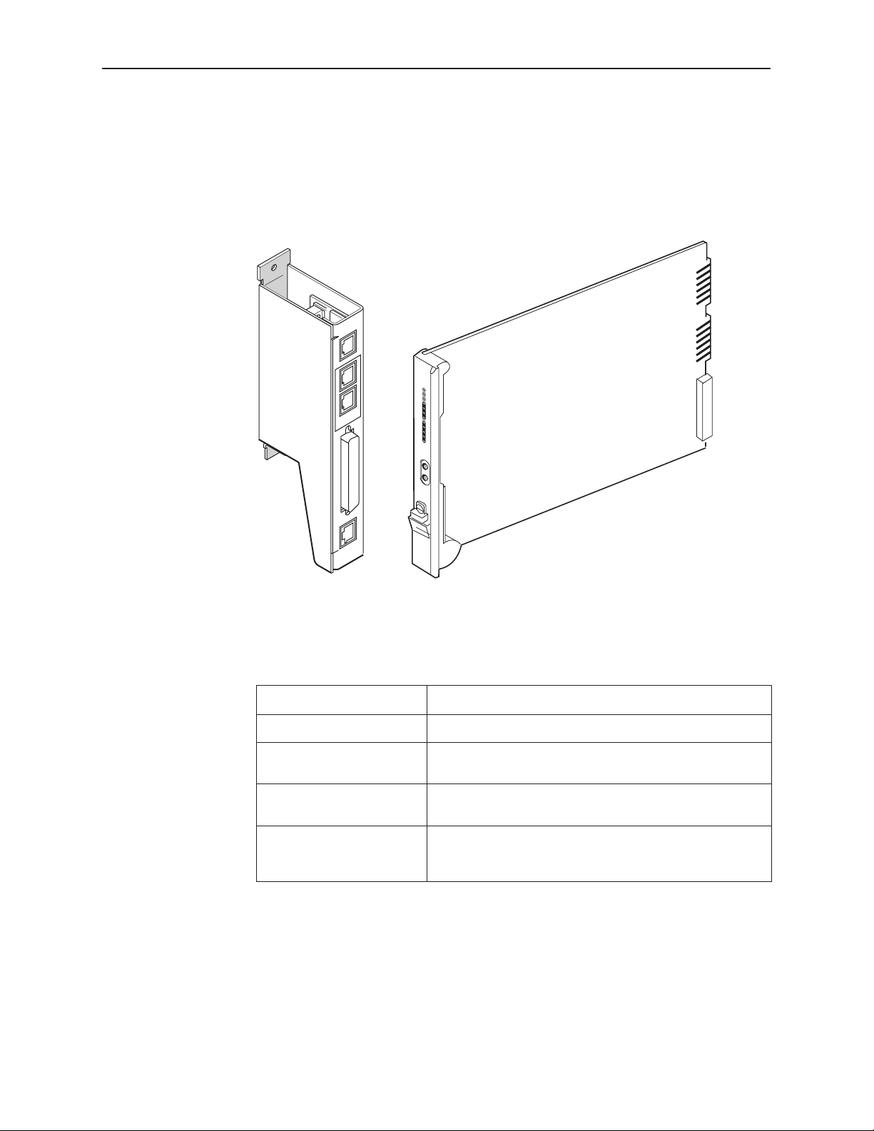
Physical Description
The Model 3166 DSU/CSU consists of a circuit card with front panel, and a rear
connector module. It is designed to be mounted in the 3000 Series Carrier.
NET
DIAGNOSTIC
CHANNEL
Introduction
Select
OK
Fail
Test
Sig
NET
OO
Alr
EE
DT
Port1
TX
RX
CT
RT
Net
Mon
In
Out
PORT 1
COM
Rear Connector
Module
DSU/CSU
3166
Circuit Card and
Front Panel
98-16076
Table 1-1. 3166 DSU/CSU Rear Connector Module Connectors
Name
NET Network interface. Provides access to the T1 network.
DIAGNOSTIC CHANNEL Provides diagnostic connectivity to other 3166 DSU/CSUs
PORT 1 DTE port. Used to connect the customer’s synchronous
COM Communications port. Provides access to a locally
Function
or a T1 auxiliary backplane.
data DTE to the DSU/CSU.
connected PC, ASCII terminal or printer, or SNMP
management link.
3166-A2-GB20-10
November 1998
1-3
Page 20

Introduction
This page intentionally left blank.
1-4
November 1998
3166-A2-GB20-10
Page 21

Installation
Important Instructions
Read and follow all warning notices and instructions marked on the DSU/CSU or
included in this guide.
2
496-15104
For a complete listing of the safety instructions, see
at the beginning of this guide.
!
HANDLING PRECAUTIONS FOR
STATIC-SENSITIVE DEVICES
This product is designed to protect sensitive components from damage
due to electrostatic discharge (ESD) during normal operation. When
performing installation procedures, however, take proper static control
precautions to prevent damage to equipment. If you are not sure of the
proper static control precautions, contact your nearest sales or service
representative.
Important Safety Instructions
3166-A2-GB20-10
November 1998
2-1
Page 22
Installation
Installation
Pr ocedure
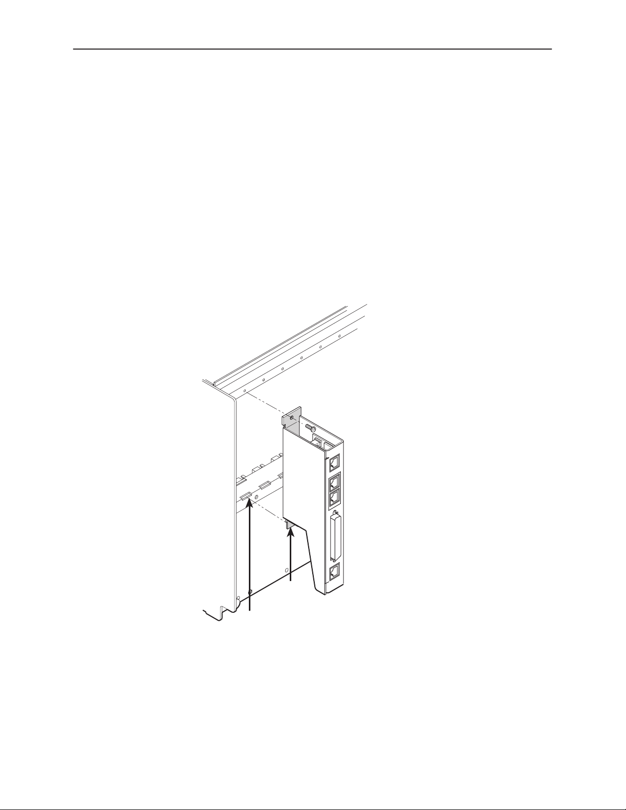
To install the DSU and rear connector module:
1. At the rear of the carrier, set the tab on the rear connector module into one of
the slotted grooves on the carrier’s backplane. Loosely fasten the screws.
Make sure the rear connector module uses the same slot position intended
for the DSU.
NOTE:
If an auxiliary backplane for Models 3151 or 3161 DSUs is installed in the
same carrier, verify that it is mounted over slots 9–16. Slot 9 is rendered
inaccessible if the auxiliary backplane is mounted over slots 1–8.
3000 Series
Carrier
Slots
Rear
Connector
Module
Tabs
98-16083
2-2
2. Loosely fasten the screw attached to the rear connector plate, allowing for
slight adjustment that may be needed when installing the DSU.
November 1998
3166-A2-GB20-10
Page 23
Installation
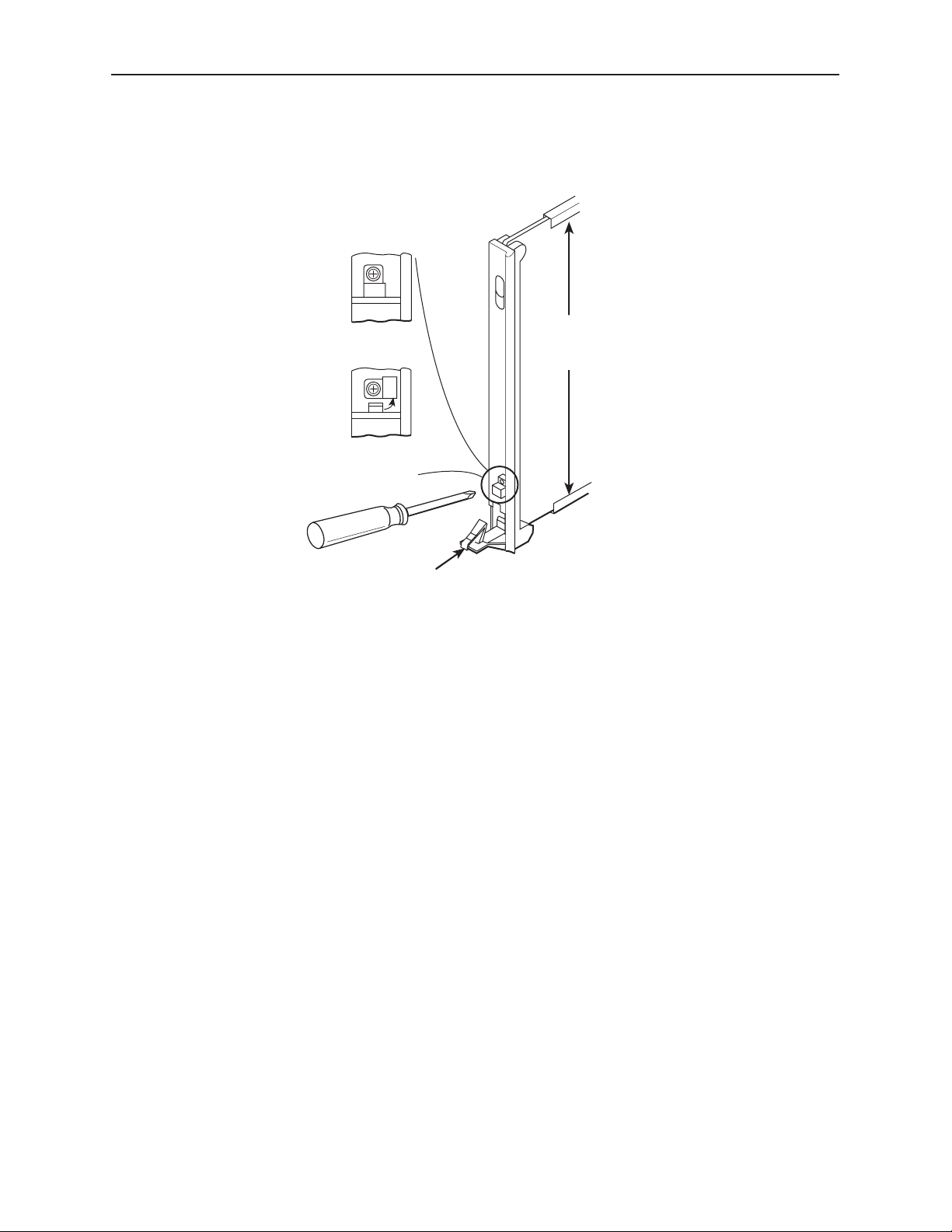
3. Using a Phillips screwdriver, loosen the screw holding the circuit pack lock
and rotate the lock to the open position. Open the latch.
Circuit
Pack
Lock
Closed
(Locked)
Open
(Unlocked)
Latch
Circuit
Card
Guides
495-14813
4. At the front of the carrier, hold the DSU vertically with the latch on its
faceplate in the open position. Then, insert the circuit card into the top and
bottom circuit card guides for the slot that contains the rear connector
module.
5. Slide the DSU/CSU into the slot, aligning the circuit card with the rear
connector module, until the connectors seat firmly into the back of the carrier.
Press the faceplate latch to secure the DSU/CSU into the carrier, rotate the
circuit pack lock into the closed position, and tighten the screw.
3166-A2-GB20-10
6. Return to the rear of the carrier and tighten the rear connector module screw.
November 1998
2-3
Page 24
Installation
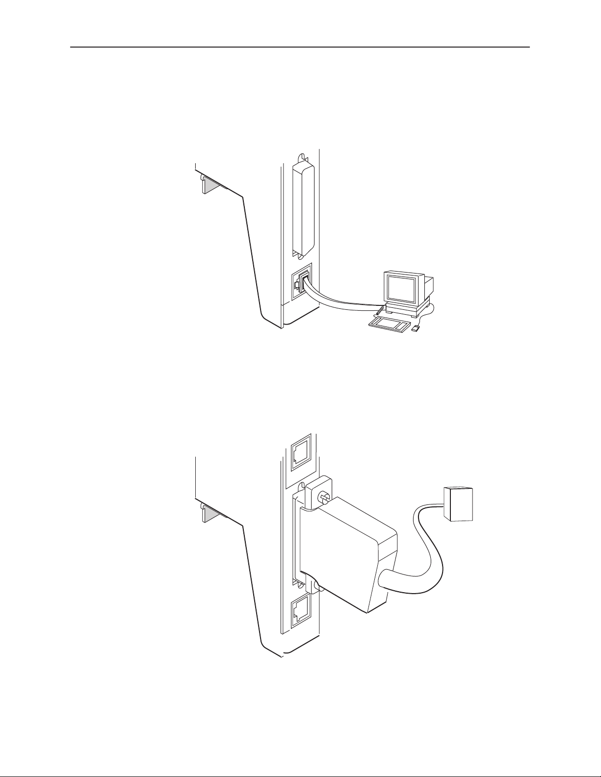
7. Attach a modular cable (not included) to the COM connector of the rear
connector module. (See Appendix D,
Pin Assignments,
for detailed cable and
connector information.) Connect the other end to a terminal or PC.
PORT 1
COM
Terminal or PC
98-16079
8. Attach the DB25 port cable to the PORT 1 connector on the rear connector
module. Connect the other end of the cable to the customer premises
equipment.
DIAGNOSTIC
CHANNEL
DTE
2-4
PORT 1
COM
November 1998
98-16078
3166-A2-GB20-10
Page 25
Installation
9. Attach the network cable to the NET connector on the rear connector module.
Connect the other end of the network cable to the connection provided by the
telephone company.
NET
Network
DIAGNOSTIC
CHANNEL
98-16077
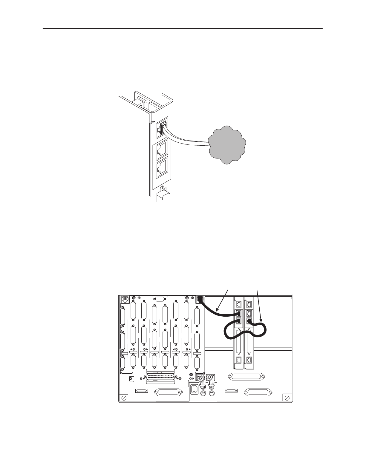
10. To daisy-chain the diagnostic channel with that of other 3166 DSU/CSUs or a
T1 auxiliary backplane, insert one end of the short diagnostic channel
extension cable into either DIAGNOSTIC CHANNEL connector on the rear
connector module. Insert the other end into either DIAGNOSTIC CHANNEL
connector of a neighboring 3166 rear connector module, or the diagnostic
channel connector of a T1 auxiliary backplane.
Diagnostic Channel
Extension Cable
DIAGNOSTIC
CHAN
PORT1PORT
1
SLOT 6 (14)
CAUTION:
PORT1PORT
2
PORT
SLOT 5 (13)
DISCONNECT ALL TELEPHONE LINES AT THE NETWORK
INTERFACE BEFORE TOUCHING OR SERVICING
PORT
1
PORT2PORT
PORT
2
SLOT 7 (15)
SLT 8 (16)
DTE DTE DTE DTE DTE DTE
DTE
MODEL NO.
3100-F1-900
COMCODE
107170409
CLOCK IN
2
SLOT 4 (12) SLOT 3 (11)
DIAGNOSTIC
CHAN
PORT
PORT
1
1
1
PORT2PORT
PORT
2
T1 NETWORK
INTERFACE
SLOT 2 (10)
PORT
1
2
PORT
2
SLOT 1 (9)
DTE
NET
DIAGNOSTIC
CHANNEL
PORT 1
COM
NET
DIAGNOSTIC
CHANNEL
PORT 1
COM
3166-A2-GB20-10
November 1998
98-16080
2-5
Page 26
Installation
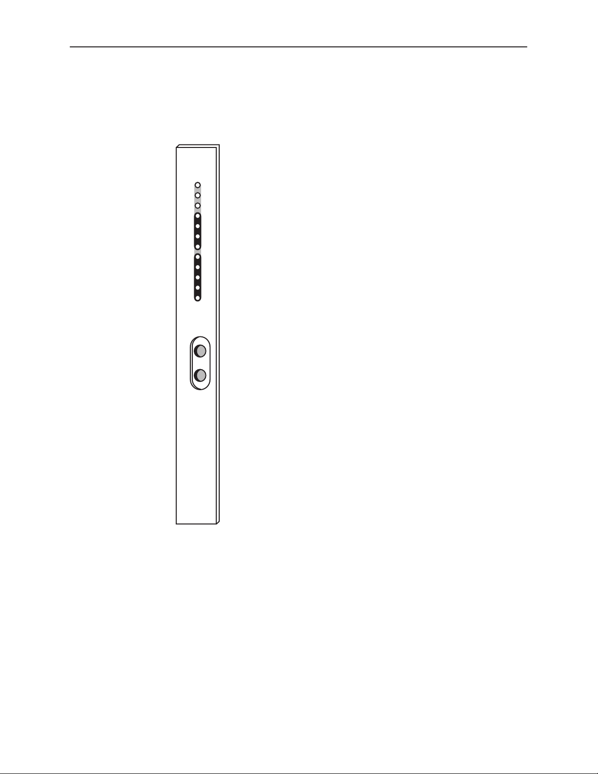
The power-up self-test begins when power is applied. During the power-up
self-test, the Fail LED flashes, then all LEDs blink twice. When the test is
complete, verify that the DSU/CSU is functional by observing that the OK and
NET Sig LEDs are lit.
Select
OK
Fail
Test
Sig
OOF
NET
Alrm
EER
DTR
TXD
Port1
RXD
CTS
RTS
Net
Mon
In
Out
DSU/CSU
3166
98-16081
2-6
November 1998
3166-A2-GB20-10
Page 27

SDCP Operation
Overview
This chapter contains information for operating your DSU/CSU using the optional
Shared Diagnostic Control Panel of the 3000 Series Carrier. It includes a
description of the SDCP and sample procedures for configuring the DSU/CSU.
3
Using the SDCP
For more information about the SDCP, refer to the
Carrier Installation Manual
The SDCP (Figure 3-1) contains a Liquid Crystal Display (LCD) and a keypad.
F1 F2
Figure 3-1. SDCP
NOTE:
You can display a graphical representation of the DSU/CSU front panel on an
attached PC (see Appendix G,
.
F3
Front Panel Emulation
COMSPHERE 3000 Series
).
3166-A2-GB20-10
November 1998
3-1
Page 28
SDCP Operation
LCD
The LCD is used to display two types of data:
Messages such as alarms, command/test completion, and action in progress
Keypad
SDCP menu tree information (see Appendix A,
SDCP Menu
)
The LCD displays status messages as requested via the Device Health and
Status branch of the SDCP menu (see
Monitoring and Testing
). In addition, the highest level status message appears on
Device Health and Status
in Chapter 4,
the front panel automatically if no front panel action has occurred at the
DSU/CSU for the past five minutes.
The LCD also lists commands, configuration options, and test results. In most
cases, the top line shows the command or option name and default value, while
the second line displays options and responses. When a response is required,
select from the options displayed directly above the Function keys (F1, F2, F3);
make your choice by pressing the corresponding Function key.
The 7-button keypad enables you to navigate through the menu tree and select
choices presented on the second line of the LCD.
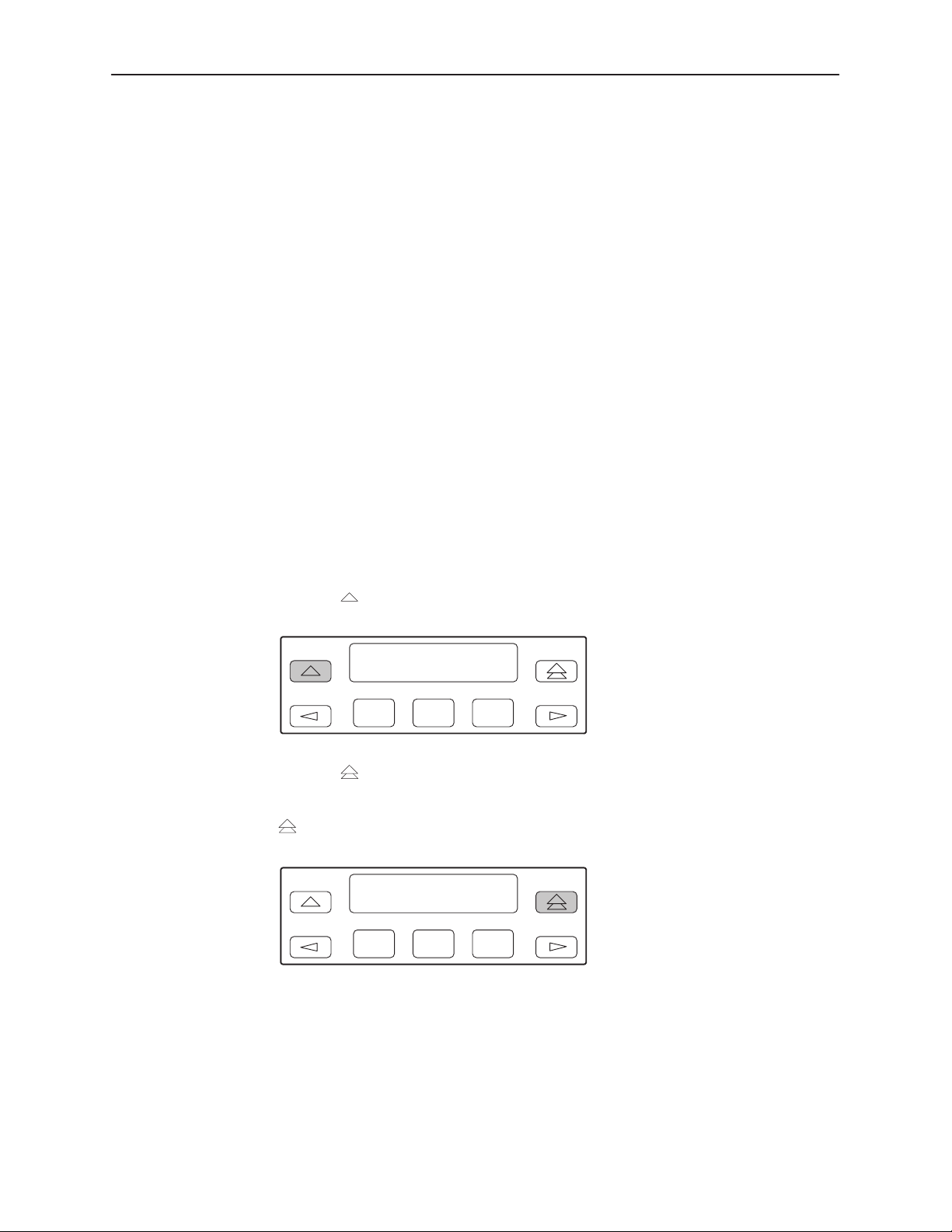
Use the
key to move up the menu.
F1 F2
F3
Use the key to exit any part of the menu in which you may be operating. You
immediately return to the top-level menu screen (see Appendix A,
SDCP Menu
),
unless you are editing configuration options. If there are unsaved changes, the
key invokes the Save Edit screen.
F1 F2
F3
3-2
November 1998
3166-A2-GB20-10
Page 29
SDCP Operation
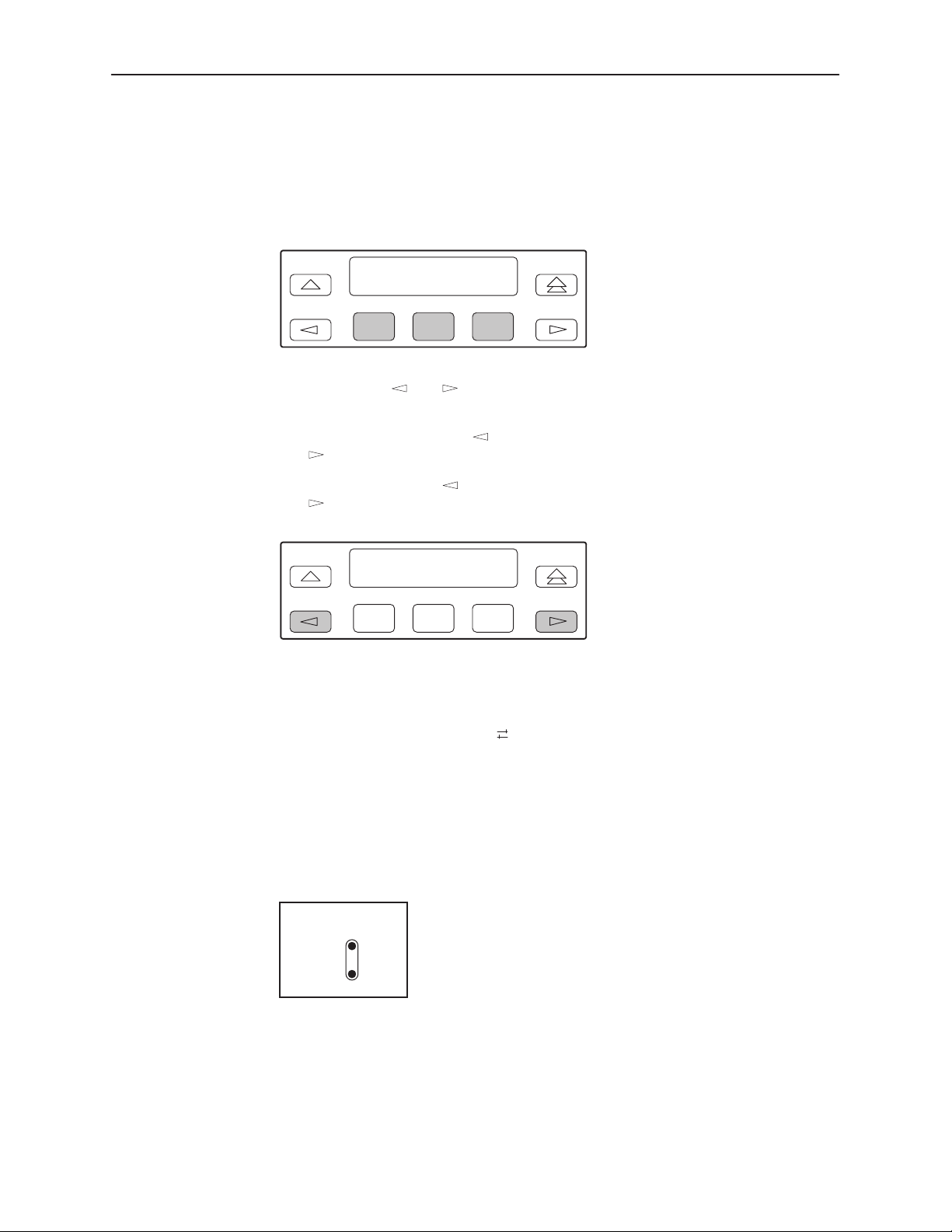
Use the Function (F1, F2, F3) keys to make selections from the choices
presented on the second line of the LCD. When this line presents choices, it is
generally divided into three sections, each displayed directly above one of the
Function keys. When your choice appears above one of the Function keys, press
that key to select that choice.
F1 F2
F3
The scroll keys ( and ) serve one of two functions, depending on whether a
menu screen or a data entry screen appears on the front panel.
For data entry screens, the
the
key scrolls one character to the right.
For menu screens, the
key scrolls to the next menu choice.
the
F1 F2
key scrolls one character to the left while
key scrolls to the previous menu choice while
F3
If a choice is available to the left of the screen, the character ← appears on the
top line. If a choice is available to the right of the screen, the → character
appears on the top line. If choices are available to both the right and the left of
the screen, two arrows appear (
). The arrows indicate that you must use the
scroll keys to bring the additional options onto the screen.
Test Jacks
3166-A2-GB20-10
Test jacks are located on the DSU/CSU front panel (Figure 3-2). These are
described in
Net
Mon
In
Out
Test Jacks
98-15942
in Chapter 4,
Monitoring and Testing
.
Figure 3-2. Test Jacks
November 1998
3-3
Page 30

SDCP Operation
LEDs
There are twelve LEDs on the 3166 DSU/CSU front panel.
A green LED indicates normal operation. A yellow LED indicates activity.
Conditions are sampled every tenth of a second.
The twelve front panel LEDs are grouped into three sections to indicate the status
of the:
System (Table 3-1)
Network Interface (Table 3-2)
Data Port (Table 3-3)
Table 3-1. System LEDs
Select
NET
Port1
In
Out
Net
Mon
OK
Fail
Test
Sig
OOF
Alrm
EER
DTR
TXD
RXD
CTS
RTS
System
LEDs
Name
OK
(Select)
Color Meaning
Green Indicates the current operational state of the DSU/CSU.
ON:
OFF:
The DSU/CSU is operational and has power.
The DSU/CSU is performing a power-up self-test or a
system failure has occurred.
BLINKING:
FAST BLINK:
A software download is in progress.
The DSU/CSU is currently selected by the SDCP.
Fail Yellow Indicates a system failure or a self-test.
ON:
A device error/fault is detected or a reset has just
occurred.
OFF:
BLINKING
No system failures are detected.
: A self-test is in progress.
Test Yellow A system test is in progress.
ON:
A loopback or pattern test has been initiated either
locally , by the network, or externally.
OFF:
No tests are active.
DSU/CSU
3166
3-4
98-16081b
November 1998
3166-A2-GB20-10
Page 31

Table 3-2. Network Interface (NET) LEDs
SDCP Operation
Select
OK
Fail
Test
Sig
OOF
NET
Alrm
EER
DTR
TXD
Port1
RXD
CTS
RTS
Net
Mon
In
Out
DSU/CSU
Network
Interface
LEDs
Name
Color Meaning
Sig Green Monitors the signal being received from the network.
ON:
A recoverable signal is being received from the
network.
OFF:
The signal cannot be recovered from the network (a
Loss of Signal condition exists).
OOF Yellow Monitors Out Of Frame (OOF) conditions on the received
network signal.
ON
: At least one OOF was detected on the signal during the
sampling period.
OFF:
No OOFs were detected on the signal during the
sampling period.
Alrm Yellow Indicates whether an alarm condition exists on the received
network signal.
ON:
An alarm condition (LOS, LOF, EER, Yellow, AIS) exists
on the received network signal. Use the Device Health
and Status command to determine the alarm type.
OFF:
No alarm condition exists on the network interface
signal.
EER Yellow Indicates the Excessive Error Rate (EER) has been exceeded
on the network interface.
NOTE: This LED is only valid when ESF framing is being
used.
ON:
OFF:
The EER has been exceeded on the network interface.
The EER has not been exceeded on the network
interface.
3166
98-16081c
3166-A2-GB20-10
November 1998
3-5
Page 32
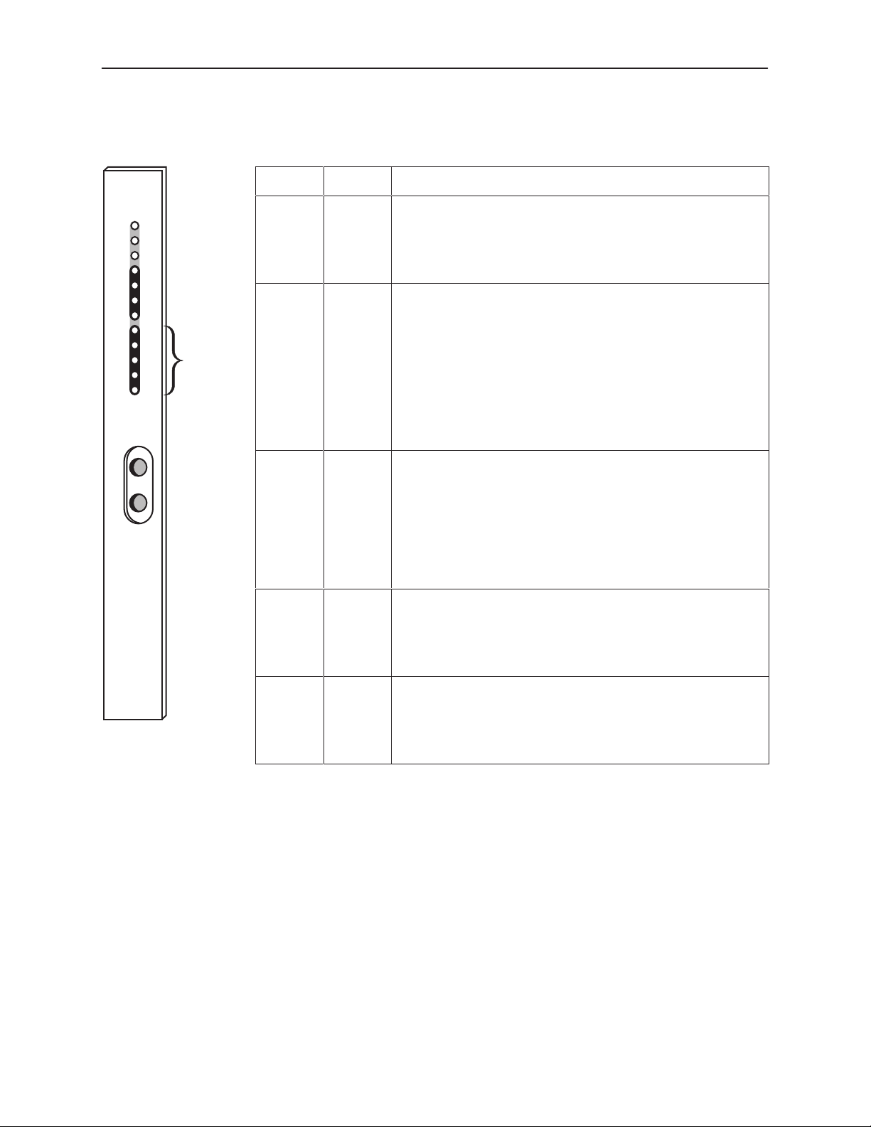
SDCP Operation
Table 3-3. Data Port (Port1) LEDs
Select
NET
Port1
In
Out
Net
Mon
OK
Fail
Test
Sig
OOF
Alrm
EER
DTR
TXD
RXD
CTS
RTS
Data
Port
LEDs
Name
Color Meaning
DTR Green Monitors the state of interchange circuit CD (CCITT 108/1, /2) –
Data Terminal Ready received from the synchronous data DTE.
ON:
OFF:
DTR is being asserted by the synchronous data DTE.
DTR is not being asserted.
TXD Green Monitors activity on interchange circuit BA (CCITT 103) –
Transmitted Data. This is the data sent from the synchronous
data DTE to the data port on the DSU/CSU.
ON:
Ones are being received from the synchronous data
DTE.
OFF:
Zeros are being received from the synchronous data
DTE.
CYCLING:
Both ones and zeros are being received from the
synchronous data DTE.
RXD Green Monitors activity on interchange circuit BB (CCITT 104) –
Received Data. This is data sent to the synchronous data DTE
from the data port on the DSU/CSU.
ON:
OFF:
CYCLING:
Ones are being sent to the synchronous data DTE.
Zeros are being sent to the synchronous data DTE.
Both ones and zeros are being sent to the
synchronous data DTE.
DSU/CSU
3166
98-16081a
CTS Green Monitors the state of interchange circuit CB (CCITT 106) –
Clear-to-Send sent to the synchronous data DTE.
ON:
OFF:
CTS is being asserted by the DSU/CSU.
CTS is not being asserted.
RTS Green Monitors the state of interchange circuit CA (CCITT 105) –
Request-to-Send received from the synchronous data DTE.
ON:
OFF:
RTS is being asserted by the synchronous data DTE.
RTS is not being asserted.
3-6
November 1998
3166-A2-GB20-10
Page 33
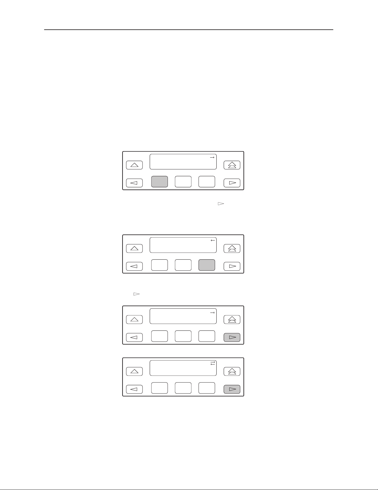
Displaying Unit Identity
The identity of the DSU/CSU (serial number, model number, software revision
level, hardware revision level, and customer identification) is available through
the Status branch of the SDCP menu (see Appendix A,
The customer identification is the only identity number you can change.
Procedure
To display the DSU/CSU’s identity (ID):
1. From the top-level menu screen, select Stat.
x:yy DSU ESF
Stat Test Cnfig
SDCP Operation
SDCP Menu
).
F1
F2
F3
2. From the Status screen, press the key until the ID selection appears on
the screen.
3. Select ID.
Status:
TStat LED ID
F1
F2
F3
4. The following screens appear in the order listed each time you press
key.
the
Identity:
xxxxxxx
Ser=
F1
F2
F3
3166-A2-GB20-10
Identity:
xxxx-xx-xxx
Mod=
F1
November 1998
F2
F3
3-7
Page 34
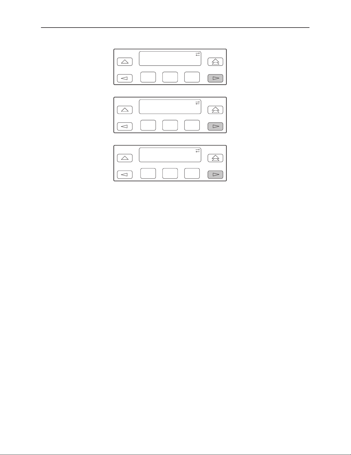
SDCP Operation
Identity:
Cust ID=
xxxxxxxx
F1
Identity:
SRev=
F1
Identity:
CCA1=
F1
F2
xx.xx.xx
F2
xxxx-xxx
F2
F3
F3
F3
3-8
November 1998
3166-A2-GB20-10
Page 35
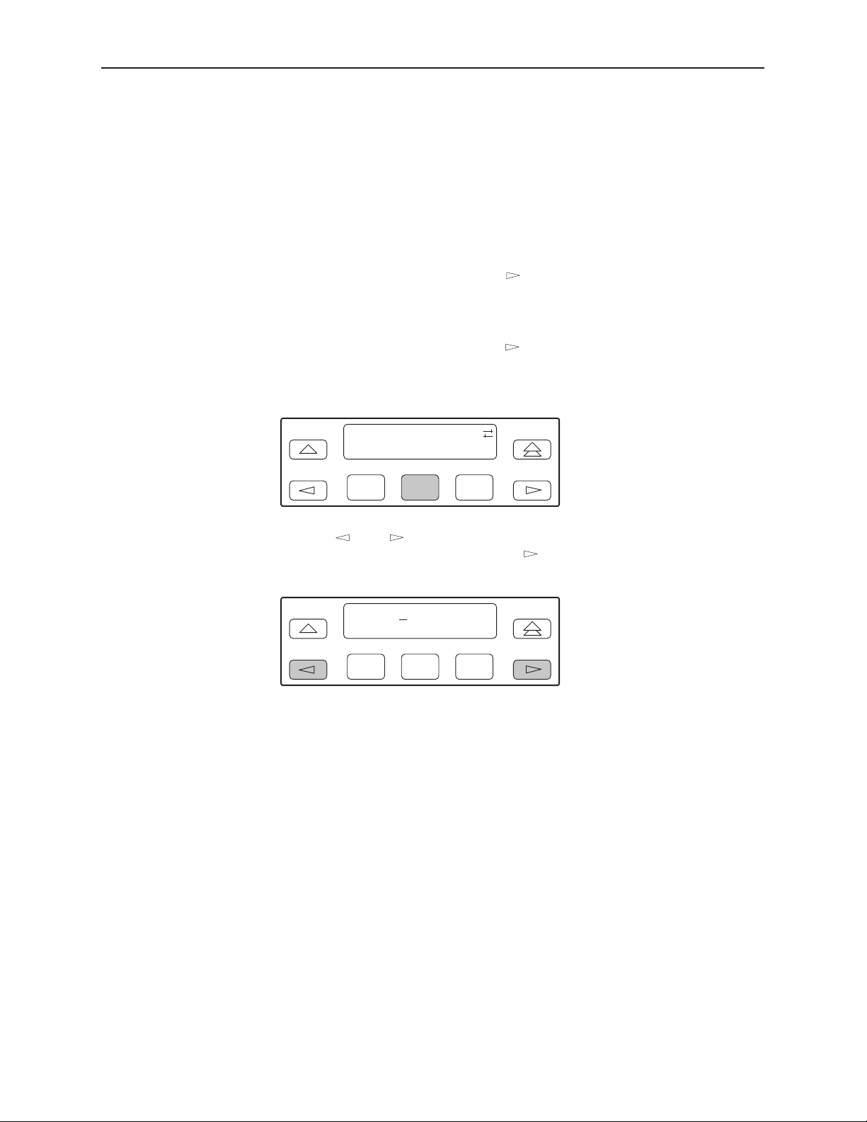
Setting Customer Identification
The customer identification is the only identity number you can change. It is used
to uniquely identify the DSU/CSU.
Pr ocedure
To change the customer identification (CID):
SDCP Operation
1. From the top-level menu, press the
key until the Ctrl selection appears
on the screen.
2. Select Ctrl.
3. From the Control screen, press the
key until the CID selection appears
on the screen.
4. Select CID.
Control:
Reset CID Passwd
F1
F2
F3
5. Use the and keys to position the cursor under the desired character.
You must enter a character before the
moves the cursor to the next
space to the right.
CustID:
xxxxxxxx
Up Down Save
F1
F2
F3
3166-A2-GB20-10
6. Enter the desired ID. Press F1 (Up) and F2 (Down) to scroll up and down
through the valid characters/numbers for the customer ID. Valid characters
are 0 through 9, #, -, ., /, A to Z, and blank space. Press F3 (Save) to save
the ID.
November 1998
3-9
Page 36
SDCP Operation
Displaying LED Conditions
The same conditions monitored by the front panel LEDs can also be monitored
by the LED command. This command is most useful when the DSU/CSU is being
accessed remotely (see Appendix G,
Panel Emulation, no LEDs are shown on the PC’s screen; you must use the Stat
command procedure described below to get LED information.
" Procedure
To display LED conditions on the front panel screen:
1. From the top-level menu screen, select Stat.
Front Panel Emulation
). When using Front
2. From the Status screen, press the
key until the LED selection appears on
the screen.
3. From the Status screen, select LED.
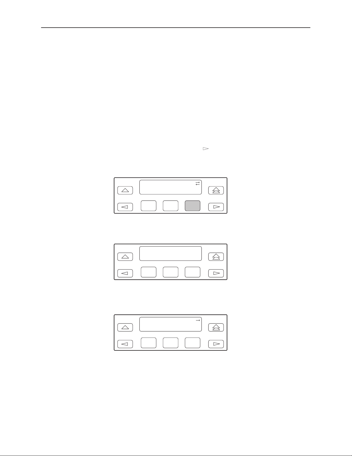
Status:
Perf TStat LED
F1
F2
F3
4. From the Select LEDs screen, press the Function key that corresponds to the
interface for which you want to display LEDs.
Select LEDs:
T1 Prt1
F1
F2
F3
If you chose T1, the LED Display screen lists the LED signals, two at a time,
on the second line. A vertical bar at the left of the LED name indicates the
condition is ON, while an underscore indicates the condition is Off.
3-10
LED Display:
_Test JNetSig
F1
F2
November 1998
F3
3166-A2-GB20-10
Page 37
SDCP Operation
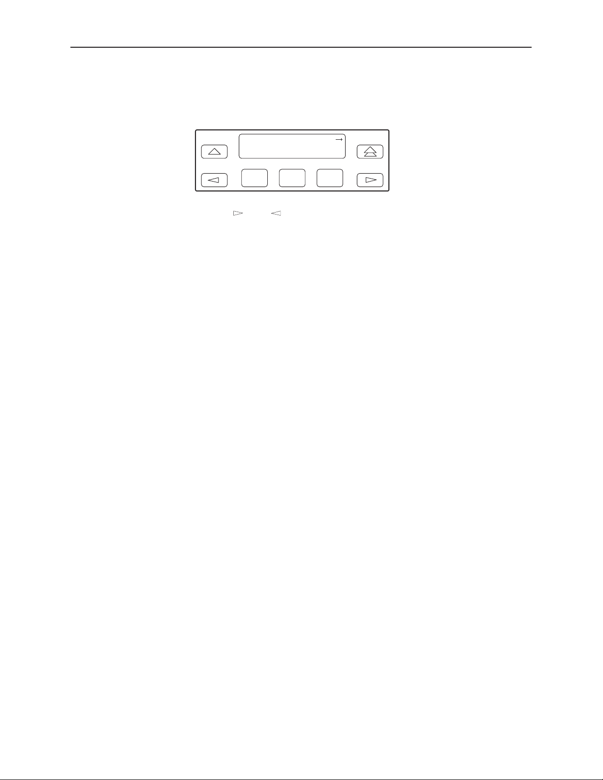
If you chose Prt1, the Port 1 LEDs screen lists the LED signals, two at a time,
on the second line. A vertical bar at the left of the LED name indicates the
condition is ON, while an underscore indicates the condition is Off.
Port n LEDs:
JDTR _TXD
F1
5. Use the and keys to scroll LED names onto the screen.
Changing Configuration Options
The DSU/CSU is an intelligent device that displays only valid options for the
current configuration. Therefore, you are only presented with menu choices that
are consistent with the current configuration and operational state of the
DSU/CSU; invalid combinations of configuration options do not appear. Be aware
that although all options are shown in this guide, what you see on your DSU/CSU
varies with your configuration.
The DSU/CSU offers configuration options located in the following memory areas:
H Active (Activ) – This is the configuration option set currently active for the
DSU/CSU. Before a configuration option set becomes active for the
DSU/CSU, you must save the set to the Active area. When the DSU/CSU is
shipped from the factory, the Active configuration option set is identical to the
Factory set. This area can be written to and controls the current operation of
the device.
H Customer 1 (Cust1) – This is the first of two sets of customer-defined
configuration options. This area can be written to.
F2
F3
3166-A2-GB20-10
H Customer 2 (Cust2) – This is the second of two sets of customer-defined
configuration options. This area can be written to.
H Factory 1 (Fact1) – This is a set of configuration options preset at the
factory. This set is determined by what is considered to be the most common
configuration used in the DSU/CSU market. Factory 1 options are read-only.
H Factory 2 (Fact2) – This is a set of configuration options preset at the
factory. This set is determined by what is considered to be the second most
common configuration used in the DSU/CSU market. Factory 2 options are
read-only.
November 1998
3-11
Page 38

SDCP Operation
The configuration options are divided into functional groups. Appendix C contains
a list of the configuration options and defaults. These groups are:
Port Interface
Network Interface
Channel
General
User Interface
Alarm
General Management
Management Trap
The DSU/CSU arrives with two preset factory default configuration settings.
These settings are based on the following:
Factory 1 – ESF framing format with B8ZS line coding format for the network
interface. Data ports are unassigned.
Factory 2 – D4 framing format with AMI line coding format for the network
interface. Data ports are unassigned.
If neither of the factory default settings support your network’s configuration, you
can customize the configuration options to better suit your application.
Use the Configuration (Cnfig) branch of the SDCP menu tree to display or change
DSU/CSU configuration options (see Appendix C,
Configuration Options
).
3-12
November 1998
3166-A2-GB20-10
Page 39

Displaying/Editing Configuration Options
Procedure
To display/edit configuration options:
1. From the top-level menu screen, select Cnfig.
DSU ESF
Stat Test Cnfig
SDCP Operation
F1
F2
F3
2. Select the configuration option set to be copied into the Edit area by using the
appropriate Function key. Use the scroll keys, if necessary.
Load from:
Activ Cust1
F1
F2
F3
3. Select Edit.
Choose Funct:
Edit Save
F1
F2
F3
4. From the Edit screen, select the functional group you want to edit by pressing
the appropriate Function key. Use the scroll keys, if necessary. (The NET
selection is shown as an example only.)
3166-A2-GB20-10
Edit:
NET Chan Gen
F1
November 1998
F2
F3
3-13
Page 40

SDCP Operation
The configuration options for the selected functional group appear on the
SDCP one option at a time. The option name appears on Line 1 with the
current value next to it. To reach other options, use the Next and Previous
selections to scroll forward and backward through the group of options.
NET Framing: ESF
Next D4 ESF
F1
F2
F3
5. Press the appropriate Function key to choose another value. Use the scroll
keys, if necessary.
6. Use the Save procedure to save your changes to the Active or Customer
area.
3-14
November 1998
3166-A2-GB20-10
Page 41
Saving Edit Changes
Procedure
SDCP Operation
Save edit changes to the Active area when you want those changes to take effect
immediately. Save edit changes to the Customer area when you want to overwrite
the existing Customer configuration options and store these changes for future
use.
NOTE:
If you attempt to exit the Edit function after making changes without
performing a Save, the DSU/CSU prompts you with Save Options? Choose
Yes or No.
To save edit changes:
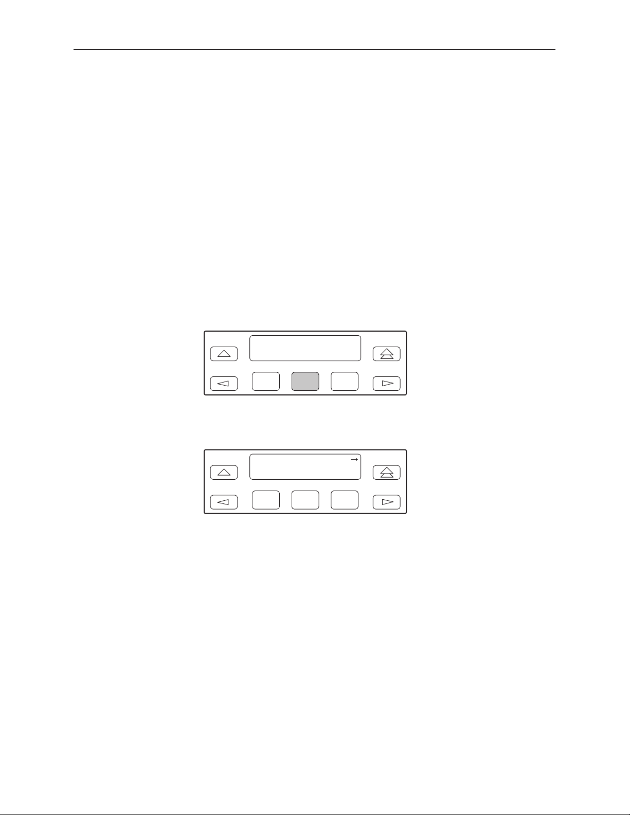
1. From the Choose Funct screen (one level above the Edit screen, two levels
below the top-level menu screen), select Save.
Choose Funct:
Edit Save
F1
F2
F3
2. Choose whether you want to save to the Active, Customer 1, or Customer 2
area. Use the scroll keys, if necessary.
Save Edit to:
Activ Cust1
F1
F2
F3
3166-A2-GB20-10
November 1998
3-15
Page 42
SDCP Operation
Enabling the Communication Port
Communication between the 3166 DSU/CSU and an external PC, ASCII device,
SNMP manager, or async terminal interface (attached either locally or through an
external modem) occurs through a communication (COM) port. Once the COM
port is enabled, other COM port configuration options can be selected.
" Procedure
To enable the COM port:
1. From the top-level menu screen, select Cnfig.
2. Select the configuration option set to be copied into the Edit area by using the
appropriate Function key. Use the scroll keys, if necessary.
3. Select Edit.
4. From the Edit screen, press the
key until the User selection appears on
the screen.
5. Select User.
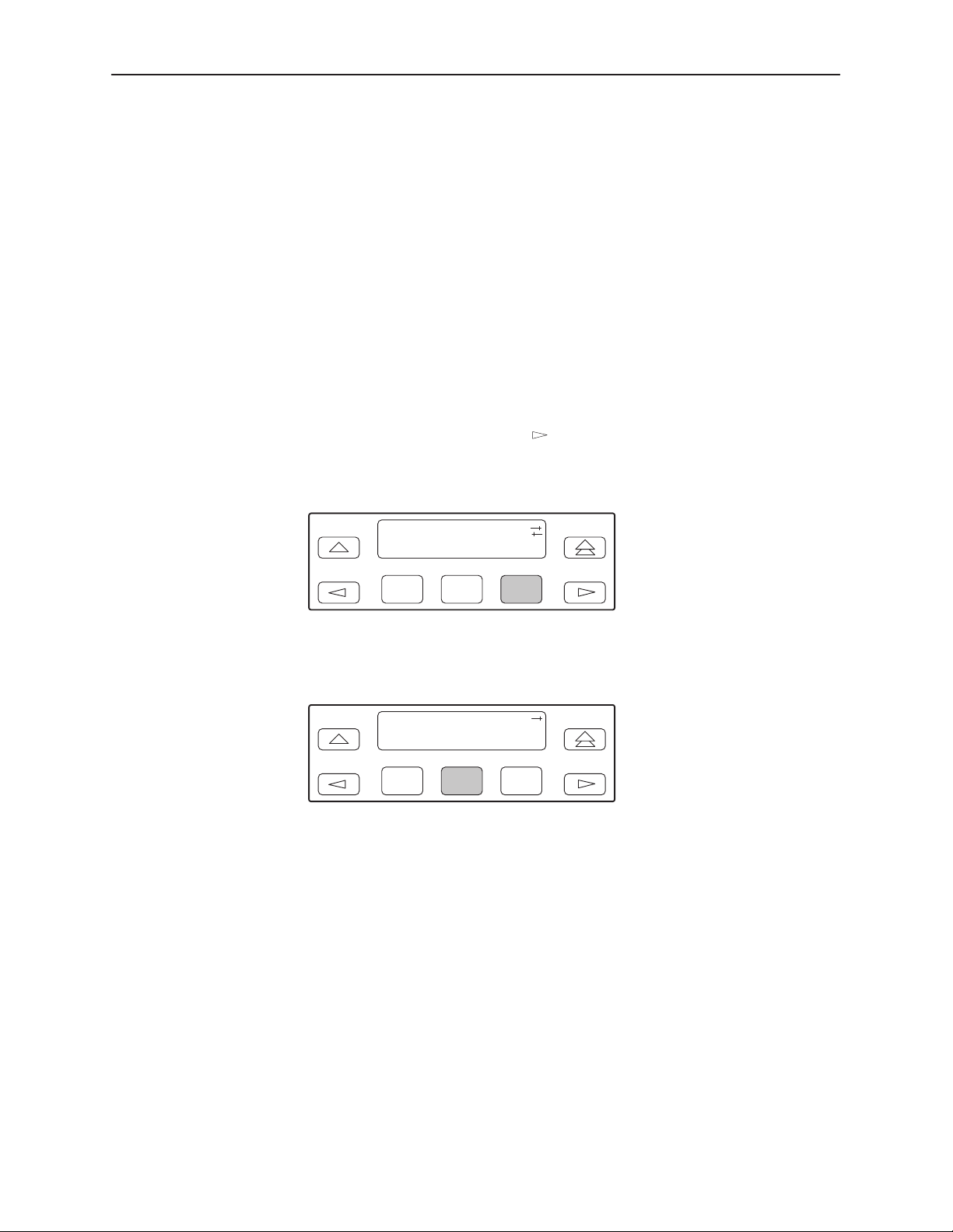
Edit:
Chan Gen User
F1
F2
F3
6. Press F1 (Next) until the Com Port configuration option appears.
7. Select Enab to enable the COM port.
Com Port:
Next Enab Disab
F1
F2
F3
The carrier COM port provides the following functionality:
H If configured for ASCII, only one ASCII device may be used for the carrier. (If
two COM ports are configured for ASCII, neither will work.)
3-16
H If configured for Mgmt, each device in the carrier can support a Mgmt COM
port; however, each Mgmt COM port must be connected to a different subnet.
To facilitate IP data routing, the device with the closest link to the SNMP
manager or Telnet client should be configured as the IP Bus Master.
H If configured for either ASCII or Mgmt, the carrier COM port may be
configured to control an external device (e.g., modem, x.25 PAD) through the
use of AT or user-specified commands.
November 1998
3166-A2-GB20-10
Page 43

SDCP Operation
The set of valid characters for control of the carrier external COM port device is
as follows:
The numbers: 0–9
The lowercase letters: a–z
The uppercase letters: A–Z
The space (“ ”) character
The ASCII symbols (in ascending order, based on the ASCII code)
The End Of Line (EOL) symbol: ←
The caret (‘‘^”) control character is used to select non-printable ASCII
characters. The caret ‘‘^” must be followed by one character which together
form the control sequence. Table 3-4 defines all of the available control
sequences.
3166-A2-GB20-10
November 1998
3-17
Page 44

SDCP Operation
Table 3-4. Control Sequence
Sequence
^A or ^a SOH 0x01
^B or ^b STX 0x02
^C or ^c ETX 0x03
^D or ^d EOT 0x04
^E or ^e ENQ 0x05
^F or ^f ACK 0x06
^G or ^g BEL 0x07
^H or ^h BS 0x08
^I or ^i HT 0x09
^J or ^j LF or NL 0x0A
^K or ^k VT 0x0B
^L or ^l FF or NP 0x0C
^M or ^m CR 0x0D
^N or ^n SO 0x0E
^O or ^o SI 0x0F
^P or ^p DLE 0x10
ASCII HEX
^Q or ^q DC1 0x11
^R or ^r DC2 0x12
^S or ^s DC3 0x13
^T or ^t DC4 0x14
^U or ^u NAK 0x15
^V or ^v SYN 0x16
^W or ^w ETB 0x17
^X or ^x CAN 0x18
^Y or ^y EM 0x19
^Z or ^z SUB 0x1A
^{ ESC 0x1B
^\ FS 0x1C
^} GS 0x1D
^^ RS 0x1E
^_
US 0x1F
3-18
November 1998
3166-A2-GB20-10
Page 45

Configuring the DSU/CSU for SNMP or Telnet
Access
To configure the DSU/CSU for SNMP or Telnet access:
Enable the SNMP agent or Telnet server within the DSU/CSU (see
Appendix C,
Select and configure the port that provides the link to the SNMP or Telnet
system.
Set the Internet Protocol (IP) address and subnet mask needed to access the
DSU/CSU (see Appendix F,
Select the link layer protocol (PPP or SLIP) for the port that provides the link
to the SNMP or Telnet system.
For SNMP links, specify the two community names (and their access levels)
that are allowed to access the device’s Management Information Base (MIB).
For SNMP links, configure the device to send traps to the SNMP manager, if
desired.
Configuration Options
).
IP Network Addressing Scenarios
SDCP Operation
).
Specify the Telnet password or SNMP validation options, if desired (see
Appendix C,
Configuration Options
).
3166-A2-GB20-10
November 1998
3-19
Page 46
SDCP Operation
Selecting the Port
The SNMP manager, Telnet device, external LAN adapter, or network device
(e.g., a router) can be directly connected to the communications (COM) port.
The COM port can support either synchronous or asynchronous PPP, or
asynchronous SLIP at data rates of up to 19,200 bps.
The example below shows how to select the COM port as the link to the SNMP or
Telnet system.
Procedure
To select the COM port as the SNMP or Telnet link:
1. From the top-level menu screen, select Cnfig.
2. Select the configuration option set to be copied into the Edit area by using the
appropriate Function key. Use the scroll keys, if necessary.
3. Select Edit.
4. From the Edit screen, press the
key until the User selection appears on
the screen.
5. Select User.
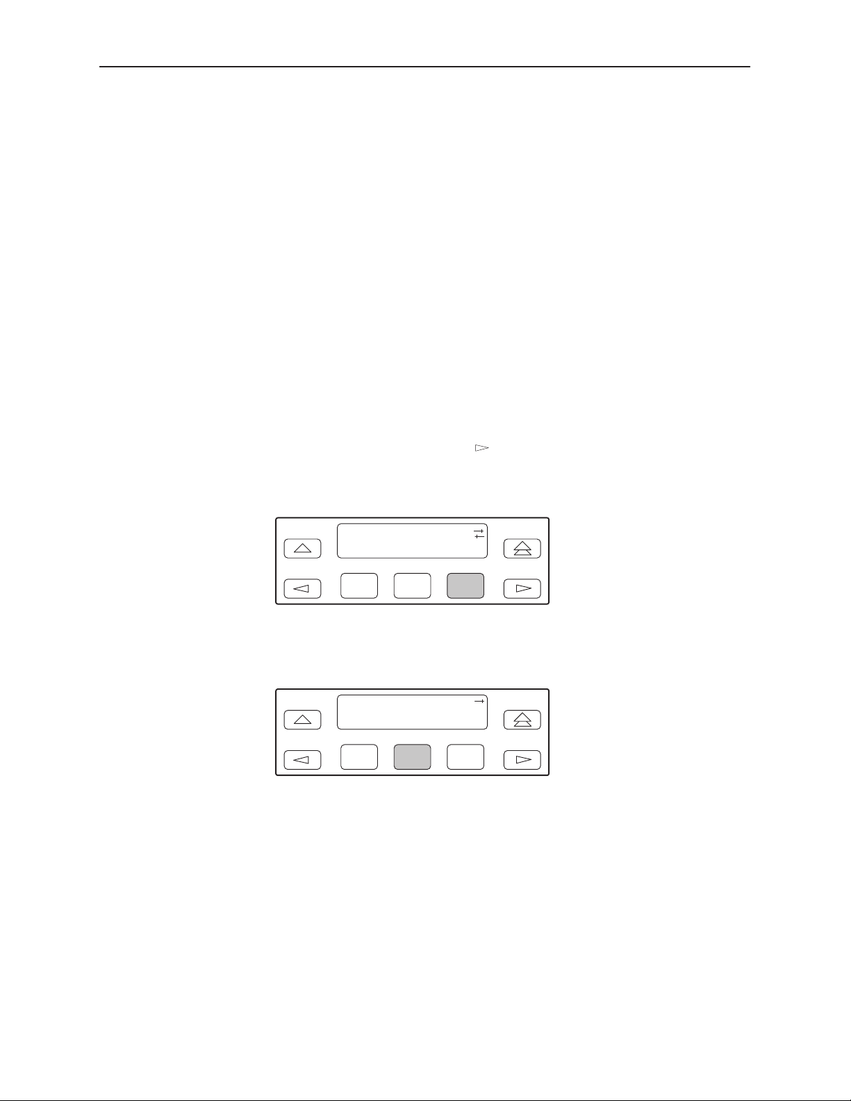
Edit:
Chan Gen User
F1
F2
F3
6. Press F1 (Next) until the Com Use configuration option appears.
7. Select Mgmt to configure the COM port as the SNMP or Telnet link.
Com Use:
Next Mgmt ASCII
F1
F2
F3
3-20
November 1998
3166-A2-GB20-10
Page 47
Setting the IP Address
Procedure
SDCP Operation
The IP address is the address used by the SNMP or Telnet system to access the
DSU/CSU (see Appendix F,
IP Network Addressing Scenarios
). For DSU/CSUs
using PPP, the IP address can be negotiated if the network device (e.g., router or
SNMP manager) supports such negotiation. The IP address is composed of four
fields with three digits per field (
xxx.xxx.xxx.xxx
).
The example below assumes that an IP address of 010.155.111.222 is being set
for the COM port. You can use the same principles to assign any value (between
000 and 255 for each digit field).
To assign an IP address to the COM port:
1. From the top-level menu screen, select Cnfig.
2. Select the configuration option set to be copied into the Edit area by using the
appropriate Function key. Use the scroll keys, if necessary.
3. Select Edit.
4. From the Edit screen, press the
key until the Mgmt selection appears on
the screen.
5. Select Mgmt.
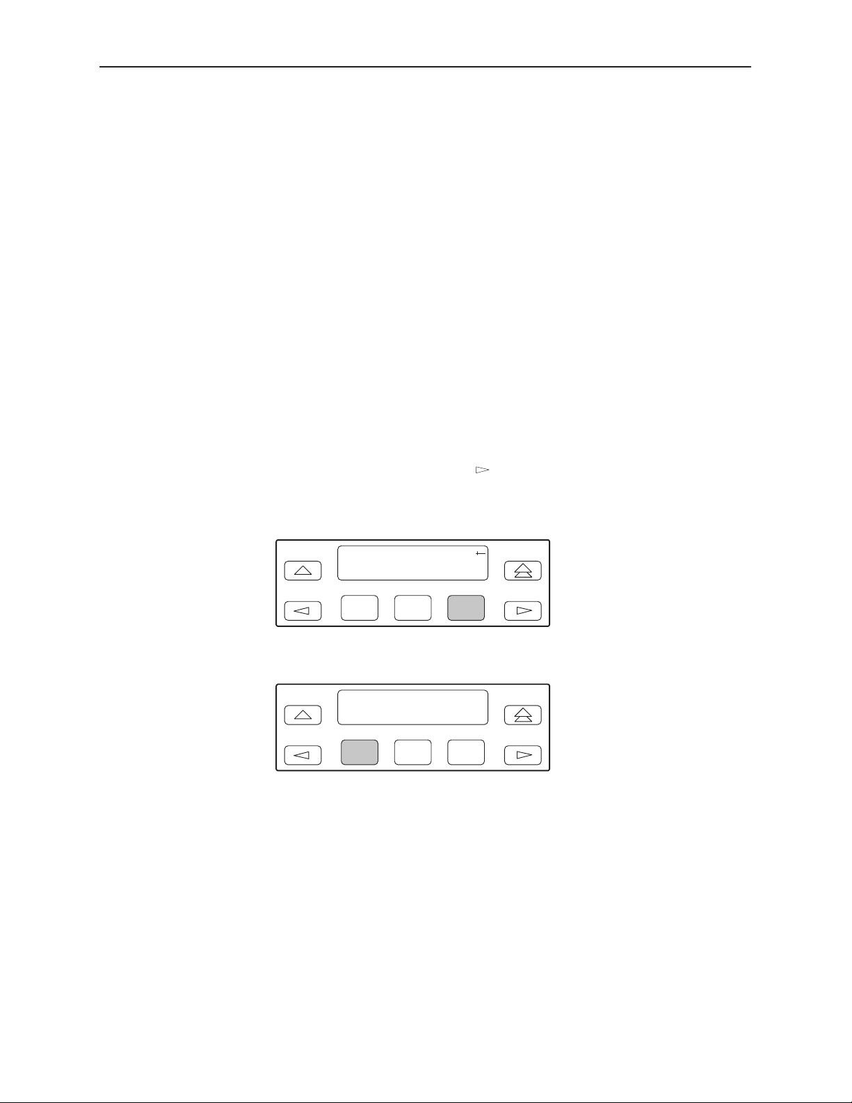
Edit:
User Alarm Mgmt
F1
F2
F3
6. From the Mgmt Config screen, select Gen.
Mgmt Config:
Gen Trap
F1
F2
F3
7. Press F1 (Next) until the Com IP Adr configuration option appears.
3166-A2-GB20-10
November 1998
3-21
Page 48
SDCP Operation
NOTE:
Steps 8 and 9 describe the process for entering an IP address. This
process applies to any IP address.
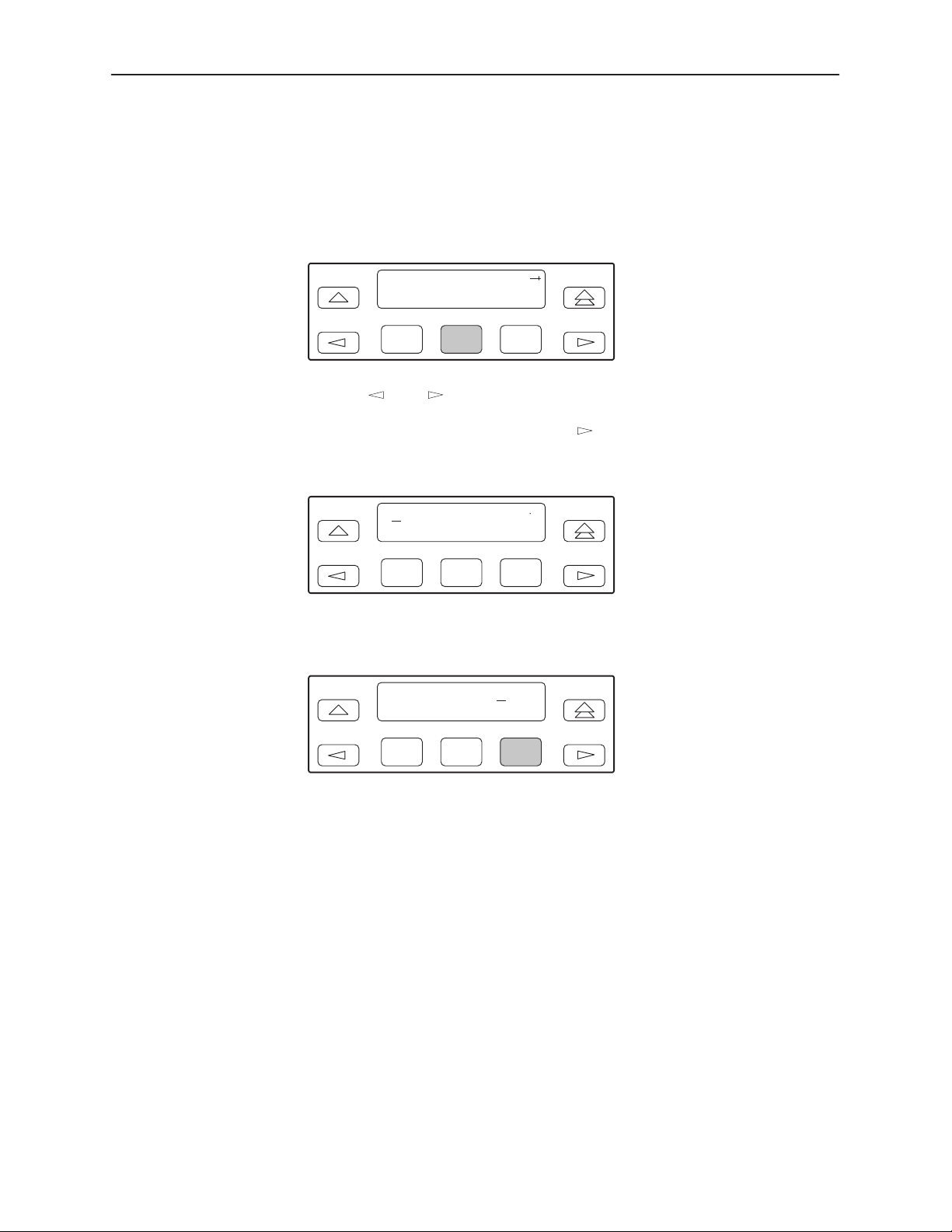
8. Press F2 (Edit) to edit the IP address. You have the option of using F3 (Clear)
to reset the IP address to the factory default
Com IP Adr:
Next Edit Clear
000.000.000.000
.
F1
F2
F3
9. Use the and keys to position the cursor under the digit you want to
change. Press F1 (Up) to increment the digit or F2 (Down) to decrement the
digit. In this example, you would press
once to place the cursor under the
middle digit in the first digit field, then press F1 (Up) once to change the 0 to
a 1. Continue in this manner to change the other digits.
000.000.000.000
Up Down Save
F1
F2
F3
10. When you are through changing the IP address, you must press F3 (Save) to
save the value. Otherwise, the original value will be retained.
010.155.111.222
Up Down Save
F1
F2
F3
3-22
November 1998
3166-A2-GB20-10
Page 49

Selecting the Link Layer Protocol
Two link layer protocols, Point-to-Point Protocol (PPP) and Serial Line Internet
Protocol (SLIP), are supported for connection to an external SNMP manager,
Telnet device, or network device (e.g., a router). PPP can be used for
synchronous or asynchronous operation. SLIP can be used for asynchronous
operation only.
The Model 3166 DSU/CSU implementation of PPP supports the following:
H Full negotiation of PPP’s Link Control Protocol (LCP).
H Active negotiation of LCP when the connection is established.
H Maximum Request Unit (MRU) sizes up to 1500 bytes, but the DSU/CSU will
attempt to negotiate down to 500 bytes.
H The DSU/CSU provides a unique LCP magic number derived from the unit
serial number and the elapsed time.
H Full negotiation of escape characters.
The Model 3166 DSU/CSU implementation of PPP does not support Link Quality
Reports (LQR), compression, encryption, Password Authentication Protocol
(PAP) or Challenge Handshake Authentication Protocol (CHAP).
SDCP Operation
The Model 3166 DSU/CSU implementation of SLIP supports a fixed MRU size of
1006 bytes.
Before selecting the protocol, you must first select the port to be used as the
communications link. Refer to
assumes that the COM port is being used as the communications link.
Selecting the Port
on page 3-20. This example
" Procedure
To select the link layer protocol:
1. From the top-level menu screen, select Cnfig.
2. Select the configuration option set to be copied into the Edit area by using the
appropriate Function key. Use the scroll keys, if necessary.
3. Select Edit.
4. From the Edit screen, press the
the screen.
key until the Mgmt selection appears on
3166-A2-GB20-10
November 1998
3-23
Page 50
SDCP Operation
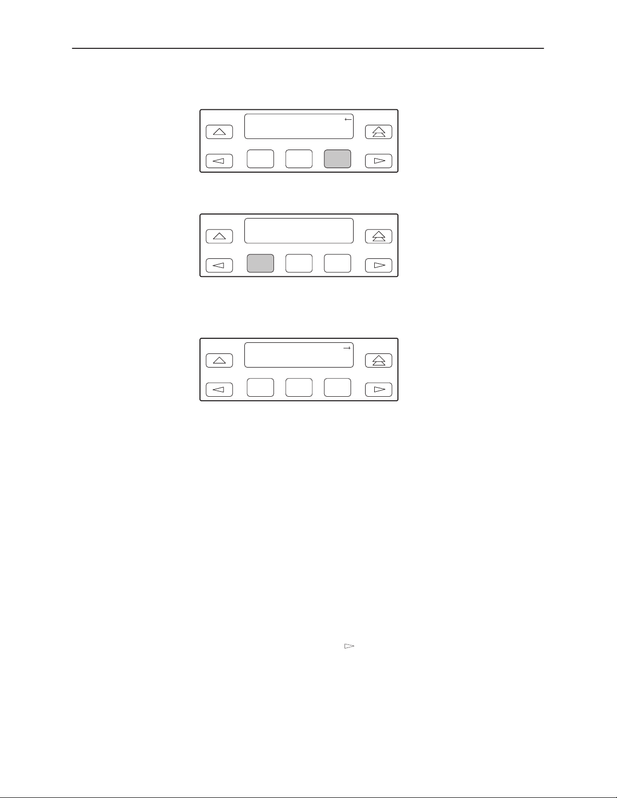
5. Select Mgmt.
Edit:
User Alarm Mgmt
F1
F2
F3
6. From the Mgmt Config screen, select Gen.
Mgmt Config:
Gen Trap
F1
F2
F3
7. Press F1 (Next) until the Com Link configuration option appears.
8. Press F2 (PPP) or F3 (SLIP).
Com Link:
Next PPP SLIP
F1
F2
F3
Specifying the Community Name(s) and Access Type(s)
You have the capability of specifying up to two community names (community
name 1 and community name 2) to be used by external SNMP managers when
trying to access objects in the DSU/CSU’s MIB. Once you specify the community
name(s), you must then specify the type of access to the MIB that SNMP
managers in the community are permitted to have.
Procedure
To specify the community name 1 and its access type:
1. From the top-level menu screen, select Cnfig.
2. Select the configuration option set to be copied into the Edit area by using the
appropriate Function key. Use the scroll keys, if necessary.
3. Select Edit.
4. From the Edit screen, press the
the screen.
key until the Mgmt selection appears on
3-24
November 1998
3166-A2-GB20-10
Page 51
5. Select Mgmt.
Edit:
User Alarm Mgmt
SDCP Operation
F1
F2
F3
6. From the Mgmt Config screen, select Gen.
Mgmt Config:
Gen Trap
F1
F2
F3
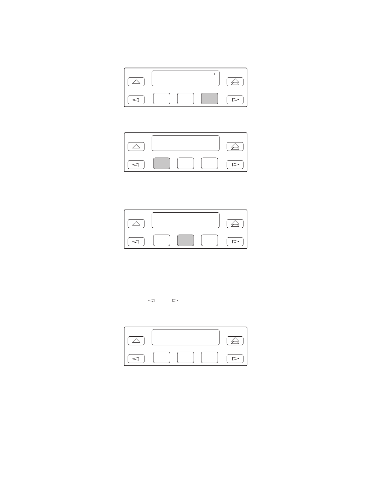
7. Press F1 (Next) until the CommunityName1 configuration option appears.
8. Press F2 (Edit) to edit the community name.
CommunityName1:
Next Edit Clear
F1
F2
F3
NOTE:
Steps 9 and 10 describe the process for entering text strings for Mgmt
configuration options. This process applies to entering any text strings
into Mgmt configuration options.
3166-A2-GB20-10
9. Use the
and keys to position the cursor under the character you want
to change. Press F1 (Up) or F2 (Down) to scroll through the valid
numbers/characters for the text string.
public
Up Down Save
F1
F2
F3
The F1 (Up) key scrolls through the ASCII character set in the following
order: numbers (0–9), lowercase letters (a–z), uppercase letters (A–Z),
space character, ASCII symbols (ascending order, based on ASCII code),
and the End of Line symbol (←). The ← erases all characters to the right of
the cursor.
10. When you are through changing the community name, you must press F3
(Save) to save the value. Otherwise, the original value will be retained.
11. Press F1 (Next) until the Access 1 configuration option appears.
November 1998
3-25
Page 52

SDCP Operation
12. Press F2 (Read) or F3 (R/W).
Access 1:
Next Read R/W
The Read selection allows read-only access (SNMP “Get”) to the accessible
objects in the MIB when community name 1 is used. The R/W selection
allows Read/Write access (SNMP “Get” and “Set”) to the objects in the MIB.
Write access is allowed for all objects specified as read/write in the MIB.
Read access is allowed for all objects specified as read-only or read/write.
Configuring SNMP Traps
A trap is an unsolicited message that is sent from the DSU/CSU to an SNMP
manager when the DSU/CSU detects certain pre-specified conditions. These
traps enable the SNMP manager to monitor the state of the network.
The SNMP Trap configuration option must be enabled for trap messages to be
sent over the communications link. You must specify the number of SNMP
managers that are to receive traps from this DSU/CSU, an IP address for each
SNMP manager specified, and the type of traps to be sent from this DSU/CSU.
For more information, refer to Appendix C,
in Chapter 4,
T raps
Enabling SNMP Trap Messages
F1
F2
F3
Monitoring and Testing
Configuration Options,
.
and
SNMP
Procedure
To enable SNMP trap messages from this DSU/CSU:
1. From the top-level menu screen, select Cnfig.
2. Select the configuration option set to be copied into the Edit area by using the
appropriate Function key. Use the scroll keys, if necessary.
3. Select Edit.
4. From the Edit screen, press the
key until the Alarm selection appears on
the screen.
5. Select Alarm.
Edit:
User Alarm Mgmt
F1
F2
F3
6. Press F1 (Next) until the SNMP Trap configuration option appears.
3-26
November 1998
3166-A2-GB20-10
Page 53
SDCP Operation
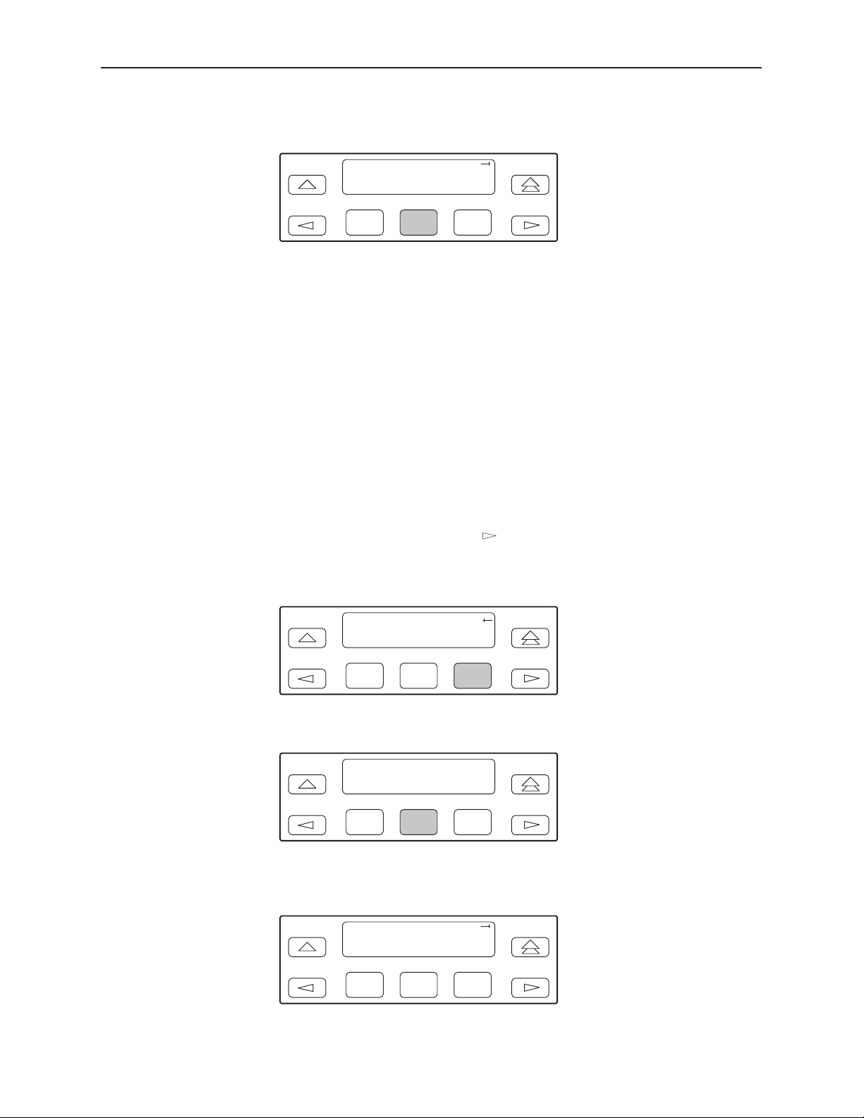
7. Press F2 (Enab) to enable trap messages over the SNMP management link.
SNMP Trap:
Next Enab Disab
F1
Selecting the Number of Trap Managers
If you intend to issue traps to an SNMP manager(s) from this device, you must
specify the number of SNMP managers that are to receive the traps.
Procedure
To specify the number of SNMP managers to receive traps from this device:
1. From the top-level menu screen, select Cnfig.
2. Select the configuration option set to be copied into the Edit area by using the
appropriate Function key. Use the scroll keys, if necessary.
3. Select Edit.
4. From the Edit screen, press the
the screen.
5. Select Mgmt.
Edit:
User Alarm Mgmt
F2
F3
key until the Mgmt selection appears on
3166-A2-GB20-10
F1
F2
F3
6. From the Mgmt Config screen, select Trap.
Mgmt Config:
Gen Trap
F1
F2
F3
7. Select the number of SNMP managers to receive traps (from 1 through 6) by
using the appropriate Function key. Use the scroll keys, if necessary.
Num Trap Mgrs:1
Next 1 2
F1
November 1998
F2
F3
3-27
Page 54
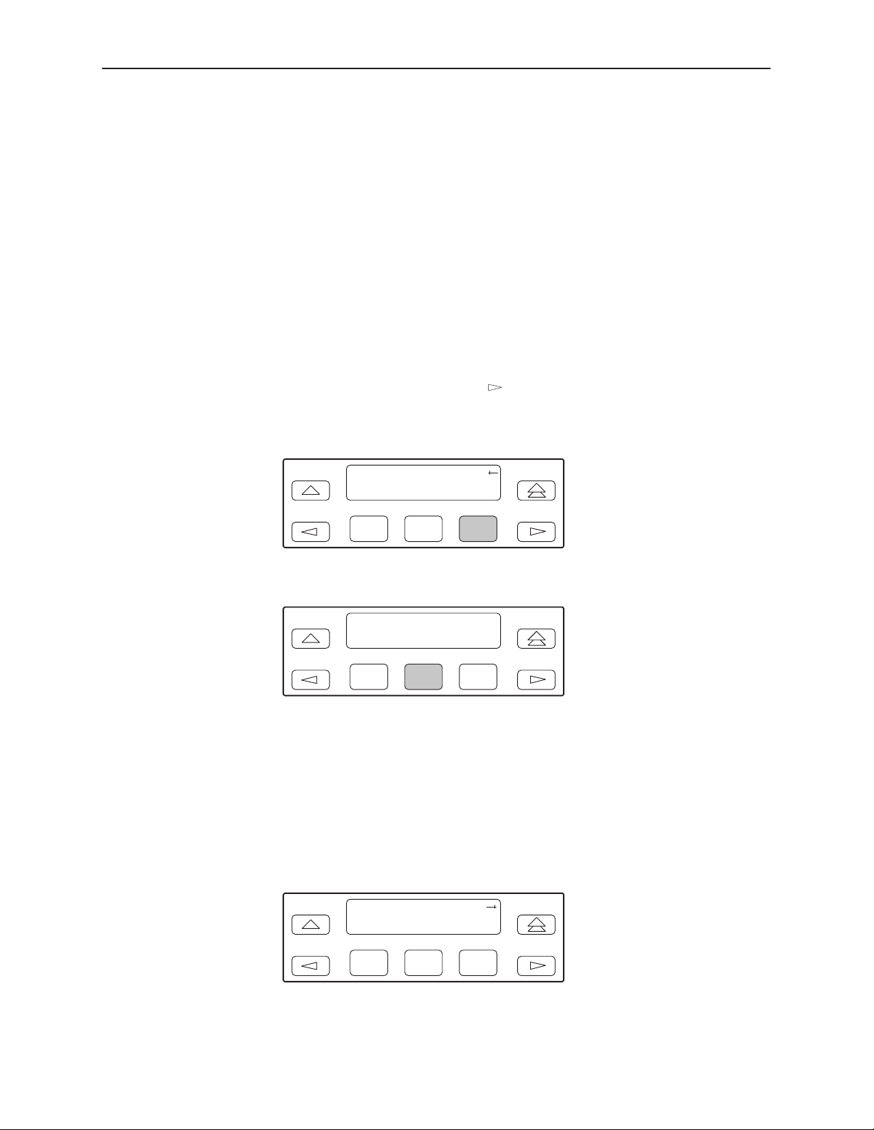
SDCP Operation
Configuring a Destination for SNMP Traps
A destination must be configured for each SNMP trap manager specified. This
configuration option is displayed for the number of trap managers specified by the
Number of Trap Managers configuration option.
Procedure
To configure an IP address for the SNMP trap manager:
1. From the top-level menu screen, select Cnfig.
2. Select the configuration option set to be copied into the Edit area by using the
appropriate Function key. Use the scroll keys, if necessary.
3. Select Edit.
4. From the Edit screen, press the
key until the Mgmt selection appears on
the screen.
5. Select Mgmt.
Edit:
User Alarm Mgmt
F1
F2
F3
6. From the Mgmt Config screen, select Trap.
Mgmt Config:
Gen Trap
F1
F2
F3
7. Press F1 (Next) until the Trapn IP Address configuration option appears.
8. Press F2 (Edit) to edit the IP address. You have the option of using F3 (Clear)
to reset the IP address to the factory default
Setting the IP Address
on page 3-21 for more information on setting an IP
000.000.000.000
. Refer to
address.
3-28
n
9. Press F1 (Next) until the Trap
Destination configuration appears, and select
the destination for the SNMP trap by using the appropriate Function key. Use
the scroll keys, if necessary.
Trapn Dst:
Next None Com
F1
November 1998
F2
F3
3166-A2-GB20-10
Page 55

Allocating Data Ports
SDCP Operation
By using the configuration options, assign a specific port to DS0 channels on the
network interface. The following methods are available to assign DS0 channels to
the port:
Block – Allows a block of contiguous channels to be assigned by specifying
a data port rate and an initial DS0 channel (the first DS0 channel in a block of
DS0 channels). The number of channels assigned is determined by the port
rate. Only those initial DS0 channel numbers that provide enough bandwidth
(based on the port’s data rate) are displayed on the screen. These channels
are automatically assigned to the destination T1 interface when the initial
DS0 channel is selected.
ACAMI (Alternate Channel Alternate Mark Inversion) – Allows a block of
contiguous channels to be assigned by specifying a data port rate and an
initial DS0 channel (the first DS0 channel in a block of DS0 channels).
However, with ACAMI, the number of channels assigned is twice the number
needed for the port rate. This is because with ACAMI, every alternate DS0
n
channel (starting with the
port, but instead always transmits and receives all ones.
+1 DS0 channel), does not carry data from the
Chan (Channel) – Individually selects the DS0 channels to allocate to the
data port. The data port rate is automatically determined based on the
number of channels selected.
Once a port is selected, you have access to the configuration options to complete
the port allocation procedure. These configuration options enable you to:
Assign the selected port to the desired interface.
Select the desired method for channel allocation.
Select the port rate and starting channel (if the allocation method is block or
ACAMI).
Select the specific channels (if the allocation method is by individual
channel).
3166-A2-GB20-10
November 1998
3-29
Page 56
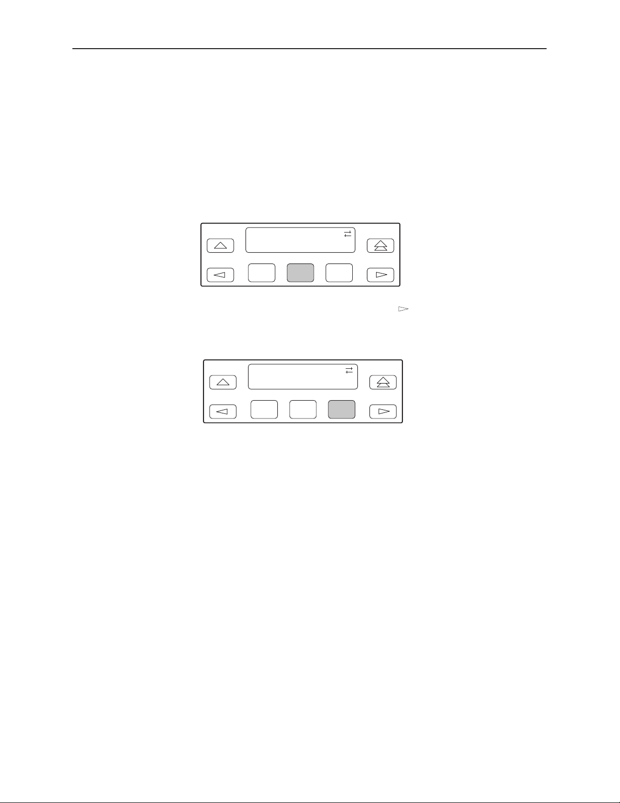
SDCP Operation
Pr ocedure
To select the data port:
1. From the top-level menu screen, select Cnfig.
2. Select the configuration option set to be copied into the Edit area by using the
appropriate Function key. Use the scroll keys, if necessary.
3. Select Edit.
4. Select Chan.
Edit:DTE
NET Chan Gen
F1
F2
F3
5. From the Channel Config screen, press the key to scroll the ports onto
the screen.
6. Select Prt1.
Channel Config:
Dsply Clear Prt1
F1
F2
F3
7. Press F1 (Next) to display the appropriate configuration options on the
screen. Use one of the following examples, depending on whether you are
assigning by block, ACAMI, or individual channel.
3-30
November 1998
3166-A2-GB20-10
Page 57
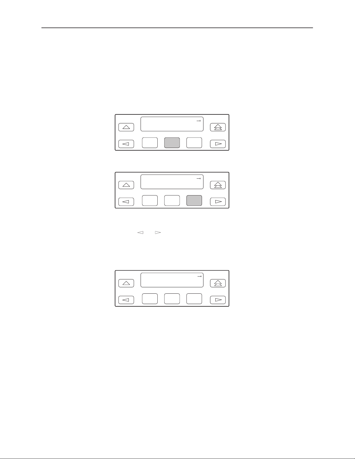
Block or ACAMI Assignment Method
The Assign By configuration option screen appears after you select a port.
Procedure
To assign by the block or ACAMI method:
1. Press F2 for Block or F3 for ACAMI.
Assign By:
Next Block ACAMI
SDCP Operation
F1
F2
F3
or
Assign By:
Next Block ACAMI
F1
F2
F3
2. Press F1 (Next) to display the next configuration option (Port Rate).
3. Use the
or key to scroll the desired port rate onto the screen. Rates
scroll in groups of three. Available selections depend on the current base rate
selected for the port. Press the corresponding Function key to select the port
rate. Then, select Next to display the Start At configuration option on the
screen.
Port Rate:384
Next 64 128
F1
F2
F3
3166-A2-GB20-10
November 1998
3-31
Page 58
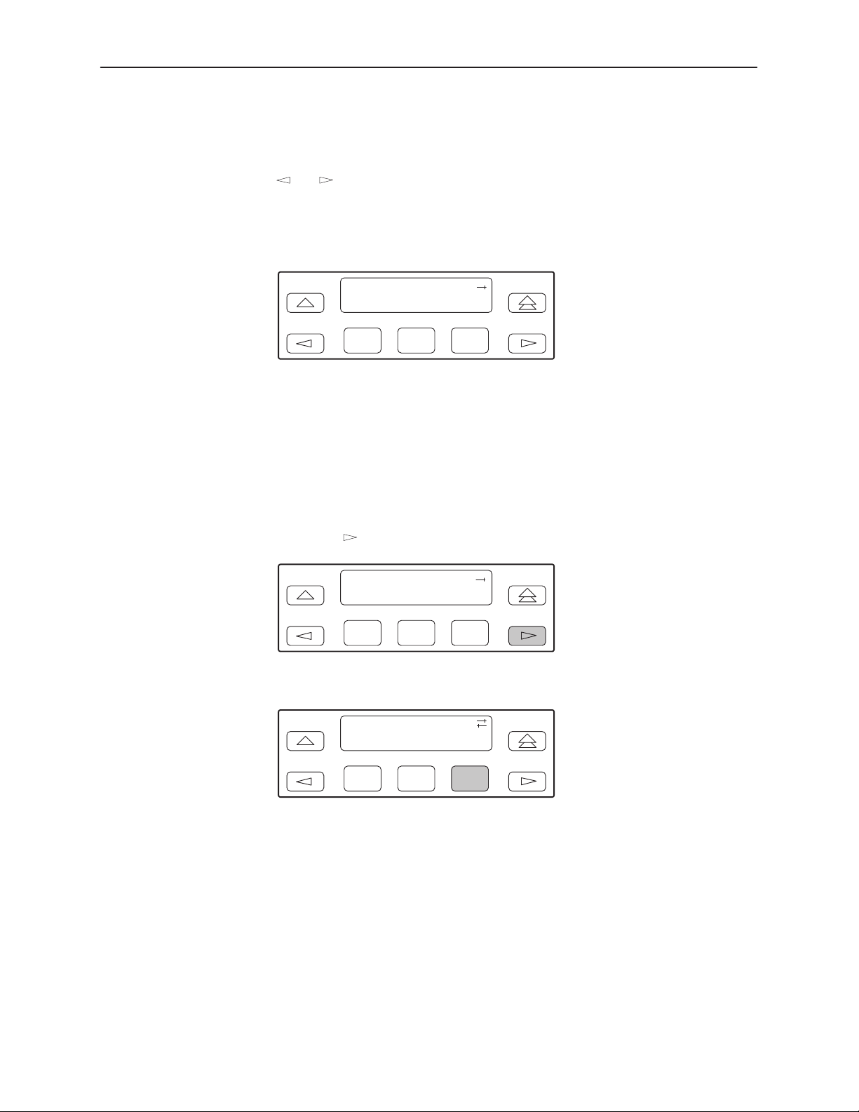
SDCP Operation
4. The Start At screen displays the configuration option used to select the
starting DS0 channel. The network channels appear on the screen.
The following screen shows an example for the network interface. Use the
or key to scroll the desired channel onto the screen. Use the Function
keys to select the starting channel. Only those DS0 channel numbers that
provide enough bandwidth (based on the configured data rate) to be used as
a starting channel number are displayed. Channel allocation for this port can
only be cleared by selecting Clear.
Start At:Clear
Next Clear N1
F1
Individual Channel Assignment Method
The Assign By configuration option screen appears after you select a port.
Procedure
To assign by the individual channel method:
1. Press the key once to bring the Chan selection onto the screen.
Assign By:Block
Next Block ACAMI
F1
2. Press F3 (Chan).
Assign By:Chan
Block ACAMI Chan
F2
F2
F3
F3
3-32
F1
F2
F3
3. Press F1 (Next) to display the next configuration option (channel allocation).
November 1998
3166-A2-GB20-10
Page 59
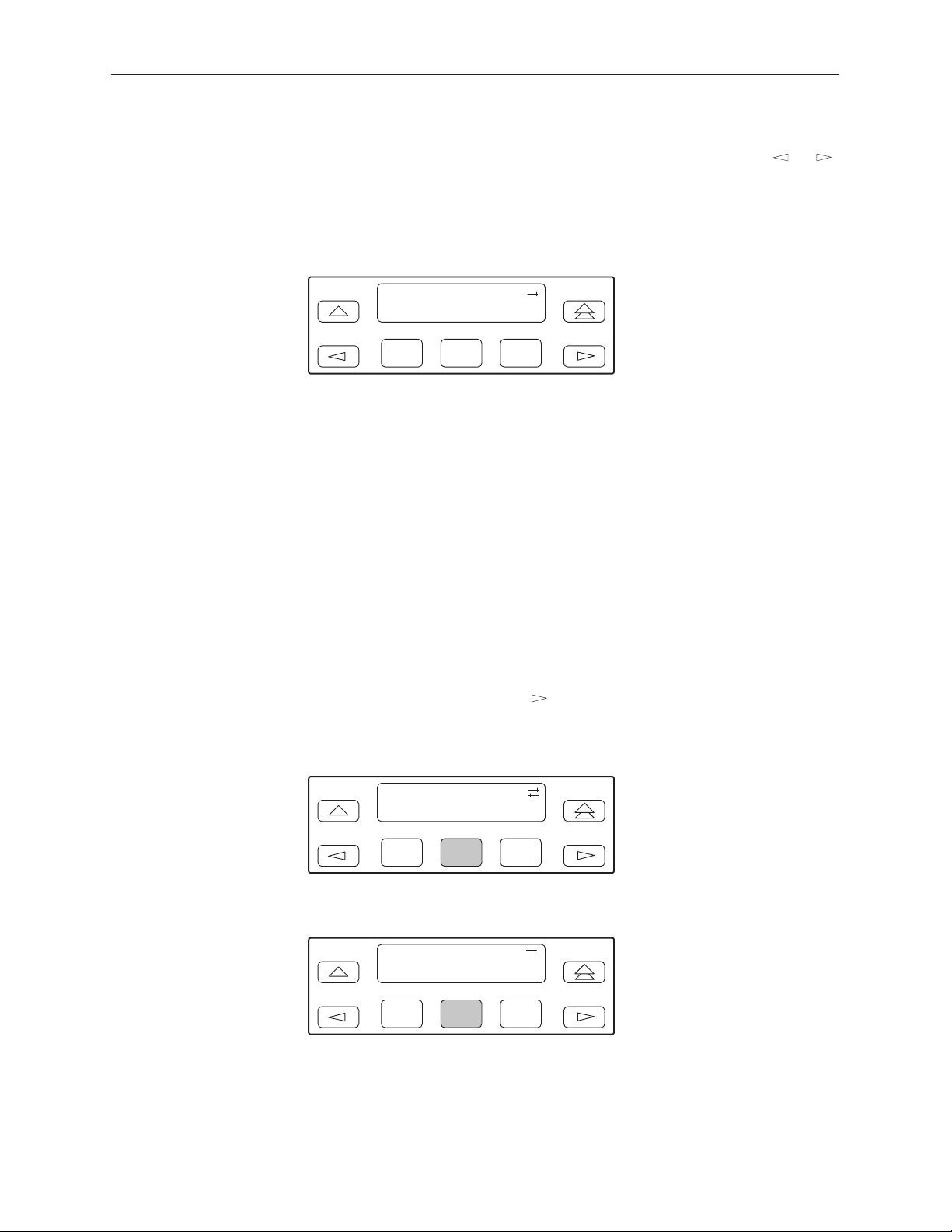
SDCP Operation
4. Line 1 displays the 24 channels for the network interface. Line 2 displays
what is allocated to the DS0 channel shown in Line 1. Pressing the
or
key scrolls the channels onto the screen in groups of three. Select the
channel by pressing the Function key under the desired number. Port
n
appears. The port is assigned to that channel. To deallocate a port, press the
Function key under that port number. Pressing the Function key under
channels assigned to other ports has no effect.
N1 N2
Next Prt1 Prt1
Clearing DS0 Channel Allocation
You can clear (deallocate) all the DS0 channels currently allocated to either the
network interface or the synchronous data ports.
Procedure
To clear DS0 channel allocation:
1. From the top-level menu screen, select Cnfig.
2. Select the configuration option set to be copied into the Edit area by using the
appropriate Function key. Use the scroll keys, if necessary.
3. Select Edit.
4. From the Edit screen, press the
the screen.
5. Select Chan.
F1
F2
F3
Edit:NET
NET Chan Gen
key until the Chan selection appears on
3166-A2-GB20-10
F1
F2
F3
6. From the Channel Config screen, select Clear.
Channel Config:
Dsply Clear Prt1
F1
November 1998
F2
F3
3-33
Page 60
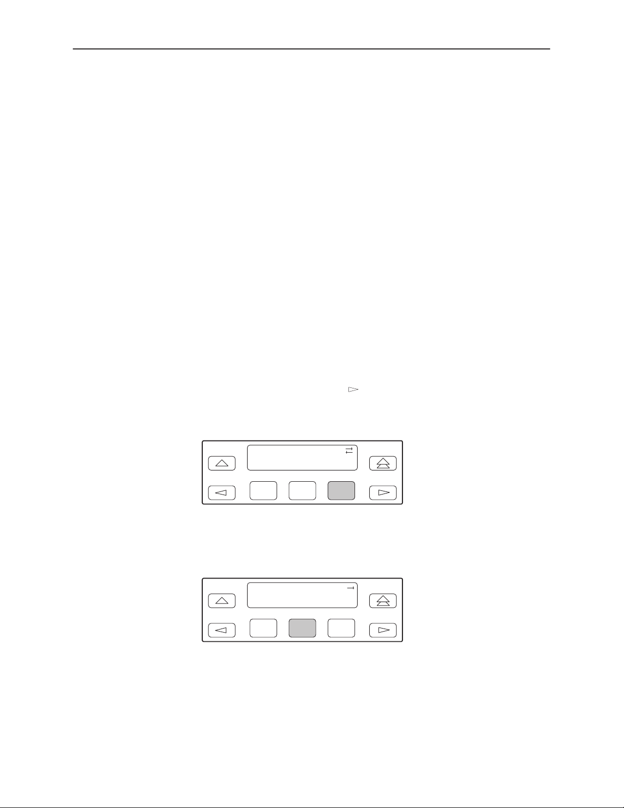
SDCP Operation
Selecting the Timing Source
The DSU/CSU provides the ability to select a master clock (timing) source
that is used to synchronize all of the T1 and data port interfaces on the
DSU/CSU. The clock for each interface is at the appropriate rate for that
interface (e.g., 1.544 Mbps for the T1 interface, the configured port rate for the
data ports), and it is independent of the master clock rate. This means that the
master clock rate and the DSU/CSU interface rates may be different.
The clock source configuration options enable you to select either the network
interface, a synchronous data port, or the internal clock.
Configuring for Network Timing
Procedure
To configure for network timing:
1. From the top-level menu screen, select Cnfig.
2. Select the configuration option set to be copied into the Edit area by using the
appropriate Function key. Use the scroll keys, if necessary.
3. Select Edit.
4. From the Edit screen, press the
key until the Gen selection appears on
the screen.
5. Select Gen.
Edit:
NET Chan Gen
F1
F2
F3
6. Press F1 (Next) to display the next configuration option (Clock Src).
7. Select the master clock source. For network, press F2 (note that network is
also the default).
Clock Src:NET
Next NET Prt1
F1
F2
F3
3-34
November 1998
3166-A2-GB20-10
Page 61
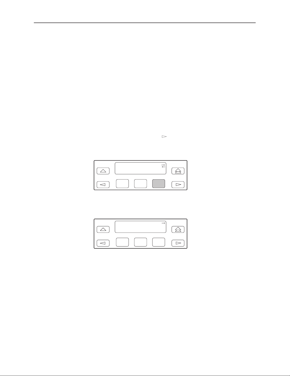
Establishing Access Security on the COM Port
Although the password feature is available, it is not required as a factory default.
If used, it ensures access security before device control is passed to a device
connected to the COM port. The default is None. The password itself is set
separately (refer to the following section,
Pr ocedure
To establish access security on a port:
1. From the top-level menu screen, select Cnfig.
2. Select the configuration option set to be copied into the Edit area by using the
appropriate Function key. Use the scroll keys, if necessary.
3. Select Edit.
Setting a Password
SDCP Operation
).
4. From the Edit screen, press the
key until the User selection appears on
the screen.
5. Select User.
Edit:
Chan Gen User
F1
F2
F3
6. Press F1 (Next) until the Password configuration option appears.
7. Select Com if it to receive password control.
Password:None
Next None Com
F1
F2
F3
3166-A2-GB20-10
November 1998
3-35
Page 62
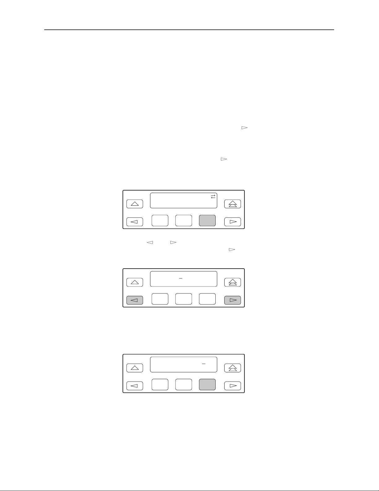
SDCP Operation
Setting a Password
In addition to establishing access security on a port (refer to the previous section,
Establishing Access Security on the COM Port
you specify otherwise, the password is null.
Procedure
To set a password:
) the password itself is set. Unless
1. From the top-level menu screen, press the
key until the Ctrl selection
appears on the screen.
2. Select Ctrl.
3. From the Control screen, press the
key until the Passwd selection
appears on the screen.
4. Select Passwd.
Control:
Reset CID Passwd
F1
F2
F3
5. Use the and keys to position the cursor under the desired character.
You must enter a character before the
moves the cursor to the next
space to the right.
Passwd:
xxxxxxxx
Up Down Save
F1
F2
F3
3-36
6. Enter the desired password. Press F1 (Up) and F2 (Down) to scroll up and
down through the valid characters/numbers for the password. Valid password
characters are 0–9, a–z, A–Z, #, –, ., and /. Press F3 (Save) to save the
password.
Passwd:
xxxxxxxx
Up Down Save
F1
November 1998
F2
F3
3166-A2-GB20-10
Page 63
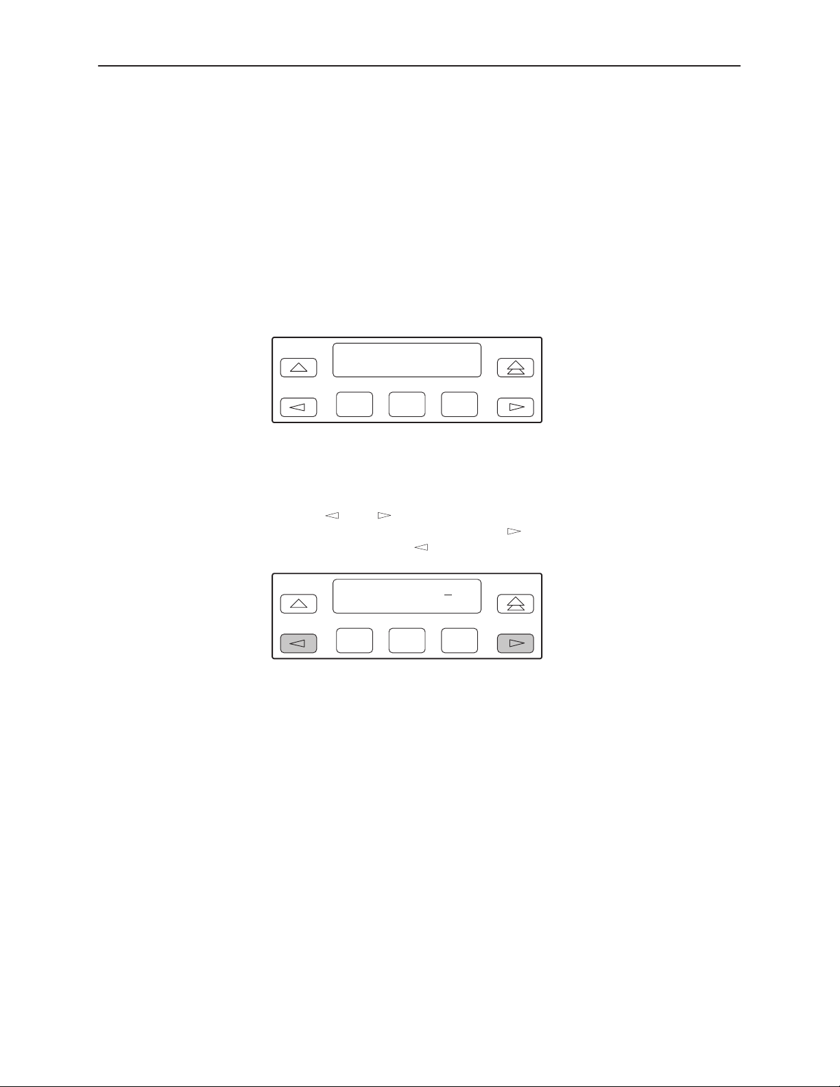
Entering a Password to Gain Access
You are prompted to enter a password (up to 8 characters) when you are
accessing a port whose Password configuration option is set (refer to the
previous section,
Valid password characters are 0–9, a–z, A–Z, #, -, ., and /. The existing
password is not shown on the screen. An underscore in the first position shows
where to enter the first character. If the password is set to all null characters
(default value), press F3 (Done) when the password screen first appears.
The following screen appears when you access a DSU/CSU that has a password
enabled.
Setting a Password
Passwd:_
Up Down Done
SDCP Operation
).
F1
F2
F3
Procedure
To enter a password:
1. Use the
You must enter a character before the
space to the right. The
2. Enter the required password. Press F1 (Up) and F2 (Down) to scroll up and
down through the valid characters/numbers for the password. You have five
minutes to enter the correct password before the DSU/CSU ends the
session.
3. Press F3 (Done) to indicate you are done entering the password. If you enter
an invalid password, the message Invalid Password appears.
and keys to position the cursor under the desired character.
key moves the cursor to the next
key is not destructive.
Passwd:
xxxxxxxx
Up Down Done
F1
F2
F3
3166-A2-GB20-10
November 1998
3-37
Page 64
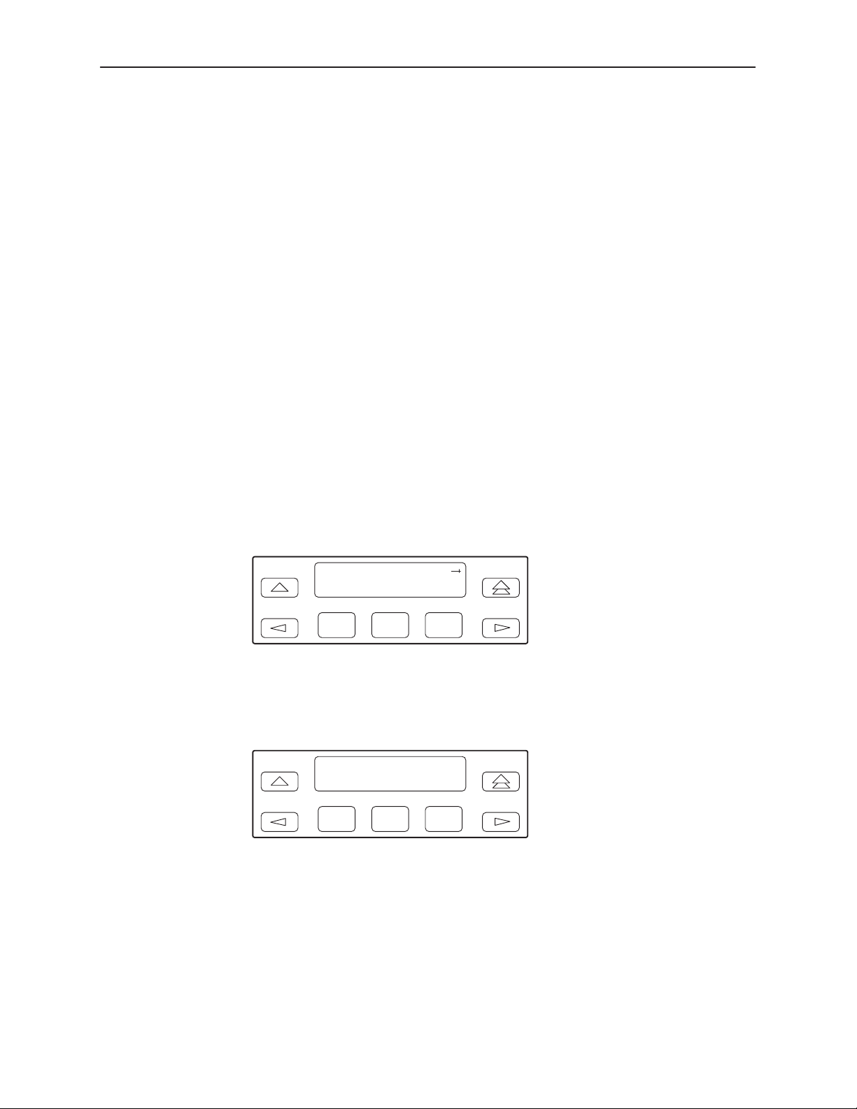
SDCP Operation
Acquiring/Releasing the User Interface
You can access the user interface from either the the COM port or the SDCP. The
DSU/CSU allows only one user interface to be active at a time. The COM port is
the default user interface at power-up or after a reset. It is also the default during
a software download or when a failure occurs at either the local or remote PC
interface.
You can switch an inactive user interface to active if:
The current active user interface has had no activity (no key was pressed) for
at least five minutes.
The active user interface has been released with the Release command of
the Control branch.
The active interface connection is broken. This includes the termination of the
front panel emulation program on a locally attached PC (if the PC supports
DTR) or the termination of the Asynchronous Terminal Interface on a remote
or locally attached terminal.
Acquiring the Active User Interface
To acquire the active user interface, press any key. If you are using the PC
interface, use the mouse to click on the desired Function key. The top-level menu
screen appears on the active user interface, regardless of what screen was
displayed at the previous active user interface.
DSU ESF
Stat Test Cnfig
F1
F2
F3
The inactive interface displays an interface active message when a Function key
is pressed or a connection is made on the inactive user interface and control
cannot be switched because the currently active interface is in use. On the
screen, either Com Port or SDCP is shown as active. For example:
DSU ESF
Com Port active
F1
F2
F3
3-38
November 1998
3166-A2-GB20-10
Page 65
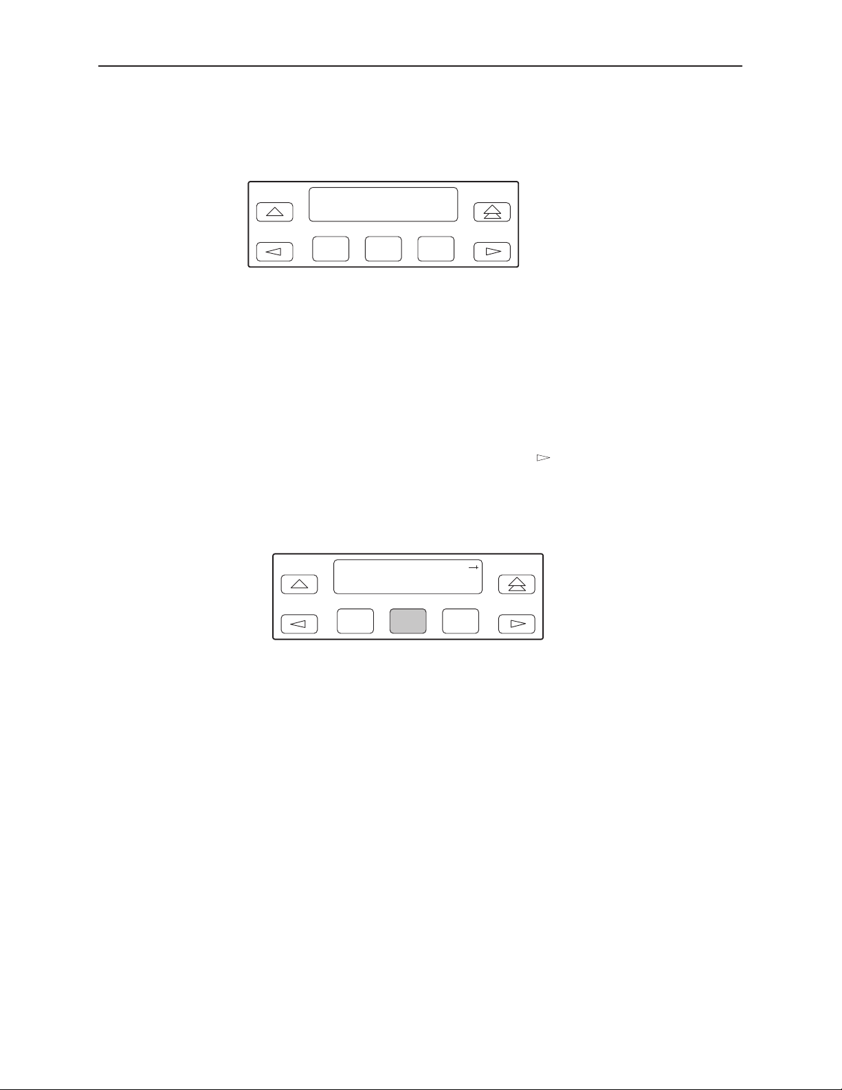
SDCP Operation
The inactive interface displays an interface idle message after control has been
released from the previously active interface and another interface has not
become active.
DSU ESF
Com Port idle
F1
Releasing the Active User Interface
To release the current active user interface, either allow five minutes to elapse
without pressing any key or use the Release command.
Procedure
To use the Release command:
1. From the top-level menu screen, press the
appears on the screen.
2. Select Ctrl.
3. From the Control screen, select Rel (Release).
F2
F3
Control:
Call Rel LED
F1
F2
F3
key until the Ctrl selection
3166-A2-GB20-10
The active user interface is released. The message Released appears. No
user interface is active until input is received from a user interface.
November 1998
3-39
Page 66

SDCP Operation
Resetting the DSU/CSU
Use the Reset command to perform a power-on reset of the DSU/CSU.
Procedure
To reset the DSU/CSU:
1. From the top-level menu screen, press the
key until the Ctrl selection
appears on the screen.
2. Select Ctrl.
3. From the Control screen, press the
key until the Reset selection appears
on the screen.
4. Select Reset.
Control:
ClrReg Reset
F1
F2
F3
5. From the Device Reset screen, press F1 to initiate a reset of the DSU/CSU
(the power-up sequence screen appears). Press F2 instead to return to the
Control screen without initiating a reset.
Device Reset:
Yes No
F1
F2
F3
3-40
November 1998
3166-A2-GB20-10
Page 67
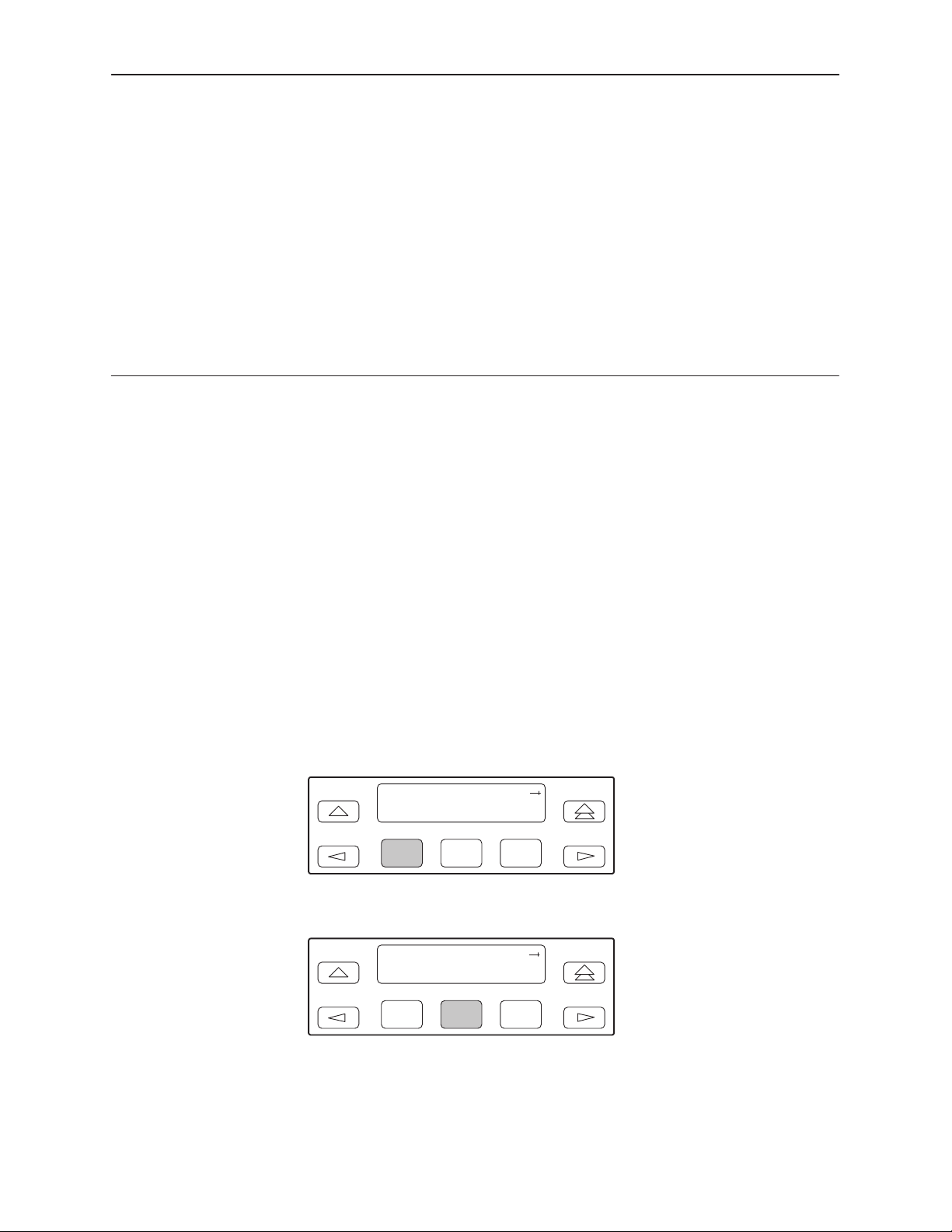
Monitoring and Testing
Overview
The 3166 DSU/CSU can detect and report faults, and perform diagnostic tests.
These features ensure that your DSU/CSU is giving you optimum performance in
your network.
Self-Test Health
4
Use the Self-Test Health command to display the results of the power-up self-test.
Possible messages are listed in Table 4-1. See Chapter 2,
information about power-up self-test.
Procedure
To display power-up self-test results:
1. From the top-level menu screen, select Stat.
DSU ESF
Stat Test Cnfig
F1
2. From the Status screen, select STest.
Status:
DevHS STest Perf
F1
F2
F2
F3
F3
Installation
, for more
3166-A2-GB20-10
November 1998
4-1
Page 68
Monitoring and Testing
3. View the results of the last power-up self-test. If no problems were found
during power-up, the following message appears.
STest Health:
Passed
F1
F2
F3
Table 4-1. Self-Test Health Messages
Message
Passed No problems were found during power-up.
CPU fail The central processing unit failed internal testing.
Device fail One or more of the unit’s integrated circuit chips failed to pass
B8ZS/LOS fail The unit failed to encode data properly or to detect Loss Of
Alarm fail The unit failed to transmit AIS or to detect an Yellow alarm.
Memory fail The unit failed program checksum verification.
NET T1 fail The unit failed to internally loop data on the network T1 circuit.
DSU fail The unit failed to internally loop data on the DSU.
DSU Port1 fail Port’s integrated circuitry failed to pass device internal testing.
Unknown Exp Dev The unit is not able to recognize the expansion device
Description
internal device level testing.
Signal.
connected to the main circuit card.
4-2
Failure
xxxxxxxx
An 8-digit hexadecimal failure code is provided for service
personnel.
November 1998
3166-A2-GB20-10
Page 69
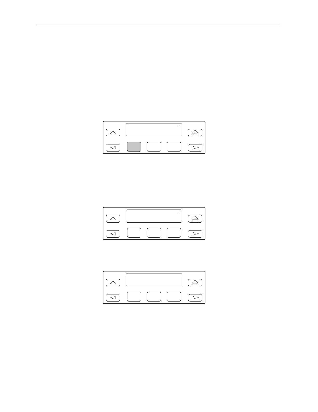
Device Health and Status
Use the Device Health and Status branch to view the current health and status
messages for the DSU/CSU. Table 4-2 lists these messages in priority order.
Procedure
To display device health and status:
1. From the top-level menu screen, select Stat.
2. From the Status screen, select DevHS.
Monitoring and Testing
Status:
DevHS STest Perf
F1
F2
F3
Alarm/status messages appear on Line 2 of the LCD in priority order (highest
to lowest). The DSU/CSU is polled for current status every ten seconds. If the
status has changed from the last poll, the Health and Status screen is
updated and the highest priority message is displayed.
3. Use the scroll keys, if necessary, to scroll additional device health and status
messages onto the LCD.
Device H/S:
OOF at DTE
F1
F2
F3
The Auto Device Health and Status screen appears when there is no activity
(no keys pressed) on the active physical interface for five minutes. Only the
highest priority message appears on Line 2 of the LCD.
Auto Dev H/S
OOF at Net
F1
F2
F3
3166-A2-GB20-10
November 1998
4-3
Page 70

Monitoring and Testing
Table 4-2. Device Health and Status Messages
Message
LOS at Net A Loss Of Signal condition (175 consecutive zeros) has been
OOF at Net An Out Of Frame condition (2 out of 4 frame synchronization bits in
AIS at Net An Alarm Indication Signal (unframed all ones signal) is being
EER at Net An Excessive Error Rate condition has been detected on the
Yellow at Net A Yellow Alarm signal is being received by the network interface.
Master Clk fail The master clock has failed. Timing for the DSU/CSU is provided
OOF at Prt1 An Out Of Frame condition has been detected on data port Port1.
EER at Prt1 The error rate of the received signal has exceeded the configured
Description
detected on the network interface. The condition is cleared when
the density of ones to zeros received is 12.5%.
error) has been detected on the network interface. The condition is
cleared when a reframe occurs.
received by the network interface.
network interface (the bit error rate has exceeded the configured
threshold for ESF framing). The condition is cleared when the error
rate falls below the threshold value.
by the internal clock.
This condition only occurs if the synchronous data port’s
Embedded Data Link (EDL) is enabled.
threshold for data port Port1. This condition only occurs if the
synchronous data port’s Embedded Data Link (EDL) is enabled.
The condition is cleared when the error rate falls below the
synchronous data port’s configured threshold value.
COM IP Down The IP management link is in a down state for the COM port. This
condition occurs if the COM port is configured for Mgmt, and
communication between the management system and the
DSU/CSU is not currently possible for this port.
Selftest failed A failure was detected during the power-on self-test. Select STest
(in the Stat branch) to display more information about the failure.
DevFail
Download failed A download attempt was interrupted and failed to complete. The
Test in progress A test is currently active. Select Tstat (in the Stat branch) to display
DSU Operational This message only appears if there are no valid alarm or status
xxxxxxxx
An internal error has been detected by the operating software. An
8-digit code appears for use by service personnel. Clear the
condition by using the Clear function under the Status branch, or by
resetting the device.
condition is cleared by resetting the device.
more test information.
messages.
4-4
November 1998
3166-A2-GB20-10
Page 71
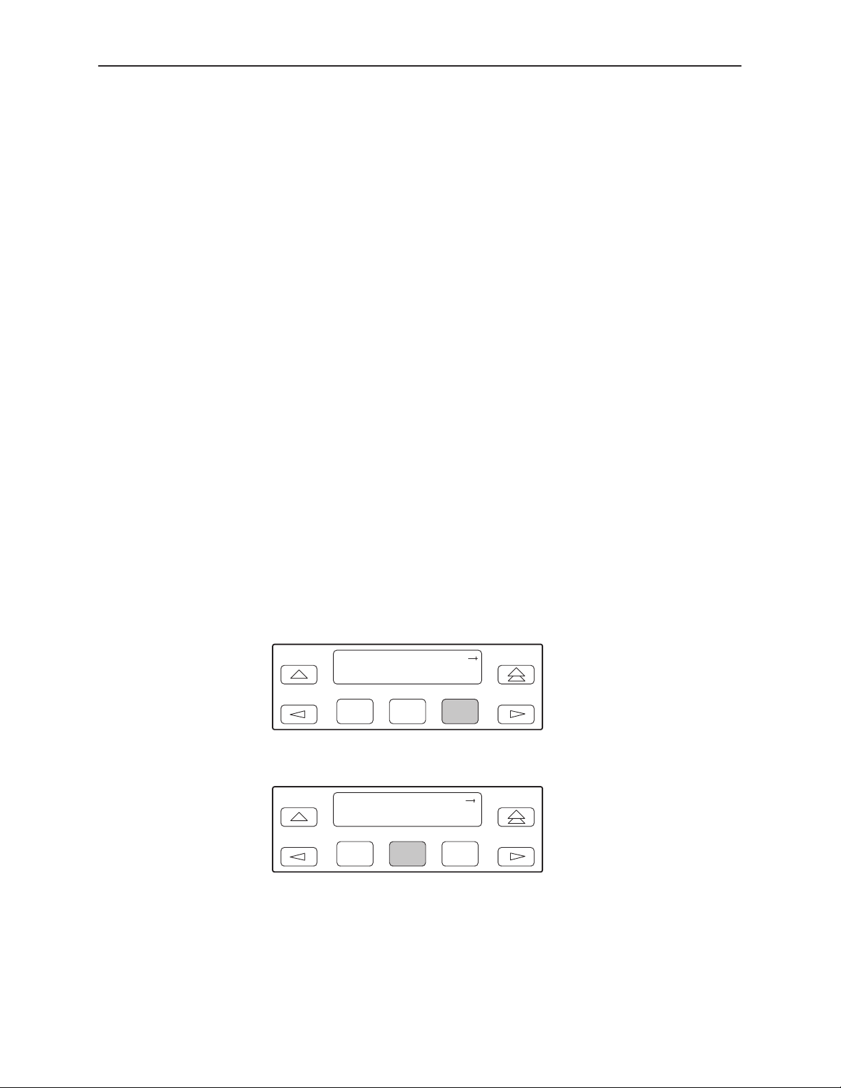
Performance Reports
When the network interface is configured for ESF operation, network
performance is continuously monitored and maintained in two sets of aggregate
registers: Carrier Network Interface Registers (Telco) and User Network Interface
Registers (User). The User registers contain an extra status register (Status
Event).
Registers shown on the front panel LCD are listed in Table 4-3. These registers
are status registers that collect performance data for the previous 24-hour period.
Performance data is updated in 15-minute intervals. After 15 minutes, the current
interval is rolled over into a set of accumulator registers that represent the
previous 96 15-minute intervals for the register. An interval total of how many of
the 96 registers contain valid data is also kept, as well as a 24-hour total for each
accumulator register.
Port performance is continuously monitored and maintained in memory registers
when the port is configured to use EDL. The DSU/CSU maintains two sets of port
registers for each synchronous data port: far-end port registers and near-end port
registers. These registers are status registers that collect performance data for
the previous 8-hour period. Port data is updated in 15-minute intervals. After
15 minutes, the current interval is rolled over into a set of accumulator registers
that represent the previous 32 15-minute intervals for the register. An interval
total of how many of the 32 registers contain valid data is also kept, as well as a
8-hour total for each accumulator register.
Monitoring and Testing
Procedure
To display User Network Interface (User) performance:
1. From the top-level menu screen, select Stat.
2. From the Status screen, select Perf.
Status:
DevHS STest Perf
F1
3. Select User registers.
Performance:
Telco User Prt1
F1
F2
F2
F3
F3
3166-A2-GB20-10
November 1998
4-5
Page 72
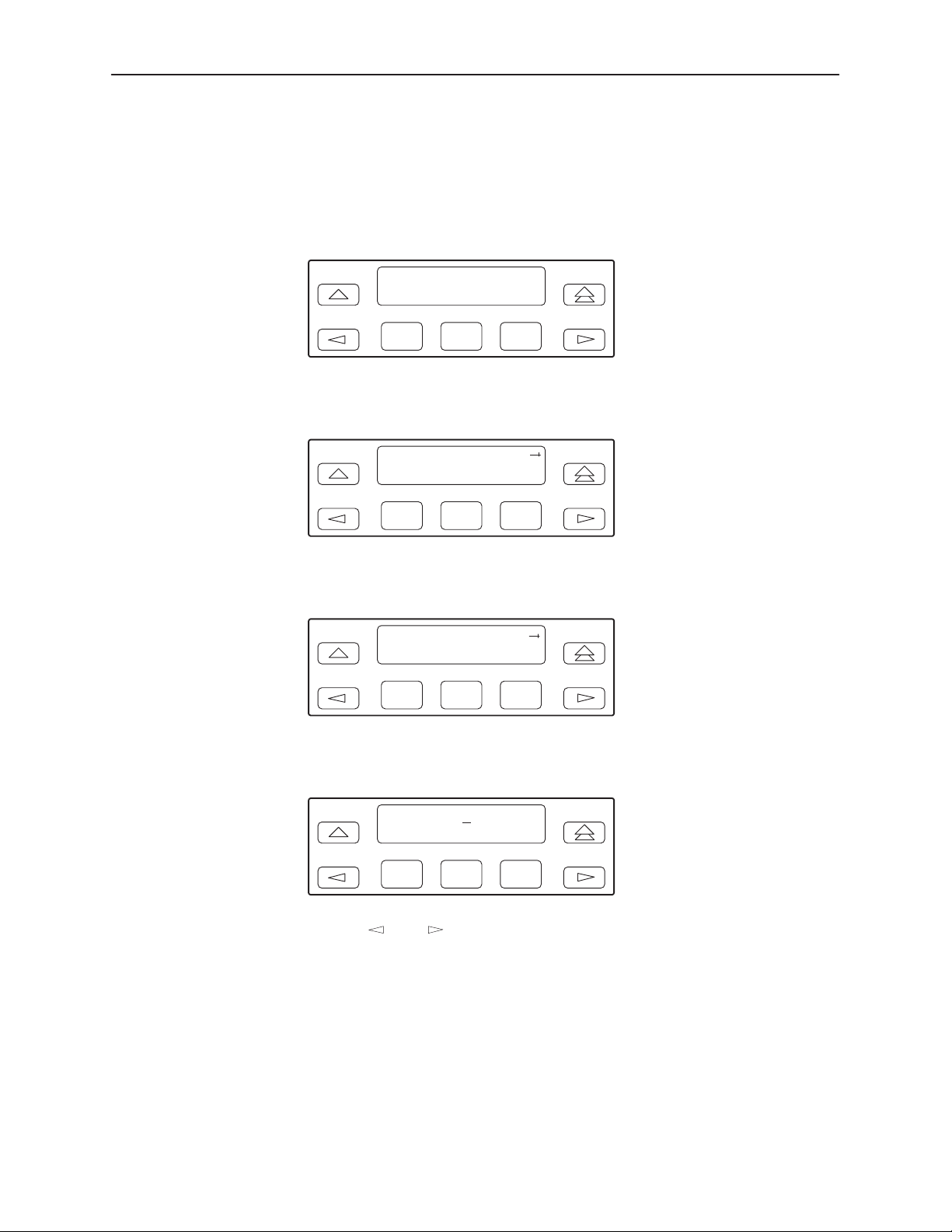
Monitoring and Testing
4. From the User Registers screen:
— Press F1 to view current registers (go to Step 5)
— Press F2 to view 24-Hour Totals (go to Step 6)
— Press F3 to view 15-Minute Interval Registers (go to Step 7)
User Registers:
Cur 24Tot Intvl
F1
F2
F3
5. When you press F1 from the User Registers screen, the User registers for
the current 15-minute interval appear.
User Current:
F1
xx,xxx
F2
F3
Event =
6. When you press F2 from the User Registers screen, the User registers for
the 24-hour total interval appear.
User 24 Hour:
VldIntvl =
F1
xx
F2
F3
7. When you press F3 from the User Registers screen, the interval screen
appears. Use this screen to choose the specific 15-minute interval.
4-6
User Intvl: 01
Up Down Dsply
F1
F2
F3
8. Use the and keys to position the cursor under the first or second digit
in the interval number displayed, then use the F1 (Up) and F2 (Down) keys to
increment and decrement the number.
November 1998
3166-A2-GB20-10
Page 73
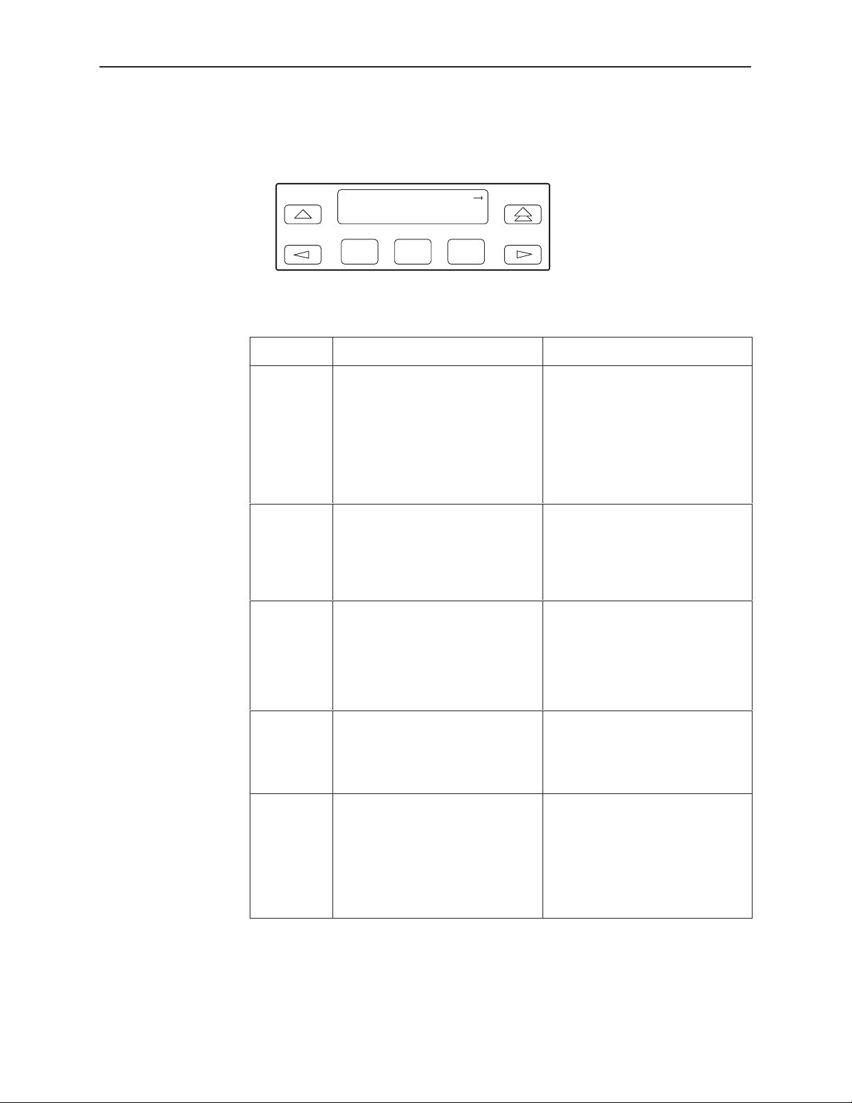
Monitoring and Testing
9. When you have selected the number of the interval you want to display, press
F3 (Dsply) to display the registers for the interval selected. Use the scroll
keys to view additional register information.
User Intvl:
ES=
xxx
F1
F2
xx
F3
Table 4-3. Performance Registers (1 of 3)
Register
Event ESF error events counter. An error
CurTimer Current interval timer. This register
Interval Description Totals Description
event is an ESF frame with either a
Cyclic Redundancy Check (CRC)
error or an Out Of Frame (OOF)
event. The maximum count is
65,535. This register is only reset
as a result of a reset command
from the network. This register is
valid for the current interval only .
records the number of seconds in
the current 15-minute interval. The
maximum is 900 seconds. This
register is valid for the current
interval only .
N/A
N/A
VldIntvl N/A Valid interval total. Records the
ES The number of errored seconds for
the current interval. An errored
second is any second with one or
more ESF error events. The
maximum is 900 seconds.
UAS The number of unavailable
seconds for the current interval. An
unavailable second is any one
second interval when service is
unavailable. (Detection occurs with
10 consecutive unavailable
seconds.) The maximum is
900 seconds.
number of valid 15-minute intervals
in the previous
24 hours for aggregate
performance and 8 hours for port
performance. This register is not
valid for the current interval.
The total number of errored
seconds for the previous x hours,
x
where
performance and 8 hours for port
performance.
The total number of unavailable
seconds for the previous x hours,
x
where
performance and 8 hours for port
performance.
x
hours, where x is
is 24 hours for aggregate
is 24 hours for aggregate
3166-A2-GB20-10
November 1998
4-7
Page 74

Monitoring and Testing
Table 4-3. Performance Registers (2 of 3)
Register Totals DescriptionInterval Description
SES The number of severely errored
seconds for the current interval. A
severely errored second is any
second with 320 or more CRC
errors, or any second with one or
more OOF events. The maximum
is 900 seconds.
BES The number of bursty errored
seconds for the current interval. A
bursty errored second is any
second with more than one, but
less than 320, CRC errors. The
maximum is 900 seconds.
LOFC The loss of frame count for the
current interval. This is a count of
the number of times that an LOF is
declared. The maximum count is
255.
CSS
(Not valid
for Port
registers.)
The number of controlled slip
seconds for the current interval.
The total number of severely
errored seconds for the previous
hours, where x is 24 hours for
aggregate performance and 8
hours for port performance.
The total number of bursty errored
seconds for the previous
x
where
performance and 8 hours for port
performance.
The total loss of frame count for the
previous
24 hours for aggregate
performance and 8 hours for port
performance.
The total number of controlled slip
seconds for the previous
where
performance and 8 hours for port
performance.
is 24 hours for aggregate
x
hours, where x is
x
is 24 hours for aggregate
x
x
x
hours,
hours,
4-8
November 1998
3166-A2-GB20-10
Page 75

Table 4-3. Performance Registers (3 of 3)
Register Totals DescriptionInterval Description
Monitoring and Testing
StEvnt
(Only valid
for User
registers.)
Complete
(Only valid
for far-end
port
registers.)
The status events register records
whether one or more of the
following events have occurred at
least once during the interval. The
event is identified by a letter as
follows:
Y – A Yellow Alarm signal has
been received on the network
interface.
L – Loss Of Signal has occurred
on the DTE Drop/Insert
(DSX-1) interface.
E – The Excessive Error Rate
threshold has been
exceeded.
F – A Frame Synchronization Bit
Error has been detected.
If none of these events occurred
during the interval, StEvnt=none
will be displayed.
Bad line conditions or loopback
tests may prevent far-end port
statistics from reaching the
DSU/CSU. This field indicates
whether the 15-minute interval
contains 900 seconds of statistics.
If one or more seconds of far-end
statistics are missing, this field will
display Complete=No, otherwise it
will display Complete=Yes. This
field is only displayed when Far is
selected from the Prt1 screen.
N/A
N/A
3166-A2-GB20-10
November 1998
4-9
Page 76
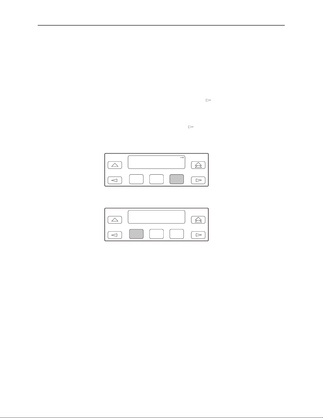
Monitoring and Testing
Resetting Performance Registers
You can reset the performance registers via the ClrReg command in the Control
branch of the front panel menu.
Procedure
To clear the performance registers:
1. From the top-level menu screen, press the
key until the Ctrl selection
appears on the screen.
2. Select Ctrl.
3. From the Control screen, press the
key until the ClrReg selection
appears on the screen.
4. Select ClrReg.
Control:
Rel LED ClrReg
F1
F2
F3
5. From the Clear Prf Regs screen, press F1 to clear the User registers.
Clear Prf Regs:
User Prt1
F1
F2
F3
If you selected User, the User performance registers are cleared, all
accumulators are reset to zero, and all status registers are cleared. The
current interval timer, the number of valid intervals count, and the total
24-hour counts are reset to zero. The Command Complete message then
appears.
4-10
November 1998
3166-A2-GB20-10
Page 77

Alarms
Monitoring and Testing
The DSU/CSU can be attached, either locally or remotely, to an ASCII terminal or
printer to display or print alarm messages. Alarms can also be displayed on a PC
that is using a terminal emulation package.
You can route these alarms to the COM port or dial them out using an external
device.
Each alarm message contains a customer identification to indicate which remote
DSU/CSU is reporting an alarm. For information about customer identification,
refer to
Possible alarm messages are as follows:
Continuous Loss Of Signal detected at the
Displaying Unit Identity
in Chapter 3,
SDCP Operation
Network Interface.
.
Alarm Cleared. Loss Of Signal condition at the
Continuous Out Of Frame condition detected at the Network Interface.
Alarm Cleared. Out Of Frame condition at the
Alarm Indication Signal received at the Network Interface.
Alarm Cleared. Alarm Indication Signal at the Network Interface.
An Excessive Error Rate has been detected at the Network Interface.
Alarm Cleared. An Excessive Error Rate at the Network Interface.
Yellow Alarm signal received at the Network Interface
Alarm Cleared. Yellow Alarm signal at the Network Interface
Continuous Out Of Frame condition detected at synchronous data
port 1.
Alarm Cleared. Out Of Frame condition at synchronous data port 1.
An Excessive Error Rate has been detected at synchronous data port 1.
Alarm Cleared. An Excessive Error Rate at synchronous data port 1.
If two alarm conditions are detected at once, the higher priority alarm is reported.
However, if an even higher priority alarm is detected before the first alarm is
cleared, the later alarm is not reported. (The alarms listed above are in priority
order with the highest priority listed first.)
Network Interface.
Network Interface.
.
.
3166-A2-GB20-10
Alarms remain active until the alarm condition is cleared. Also, an alarm clear
message is only sent when there are no other alarms active.
For information about alarm configuration options, refer to
Options
For troubleshooting information, refer to
in Appendix C,
November 1998
Configuration Options
Troubleshooting
.
Alarm Configuration
on page 4-14.
4-11
Page 78

Monitoring and Testing
SNMP Traps
SNMP traps are unsolicited messages that are sent from the DSU/CSU to an
SNMP manager when the DSU/CSU detects certain pre-specified conditions.
These traps enable the SNMP manager to monitor the state of the network.
The SNMP Trap configuration option must be enabled for trap messages to be
sent over the communications link. You must specify the number of SNMP
managers that are to receive traps from this DSU/CSU, an IP address for each
SNMP manager specified, and the type of traps to be sent from this DSU/CSU.
For more information, refer to Appendix C,
Configuring SNMP Traps
Trap types consist of the following:
General traps – Include warmStart and authenticationFailure. The DSU/CSU
sends a warmStart trap after it has been reset to indicate that it has just
reinitialized itself. The DSU/CSU sends an authenticationFailure trap when it
has received an SNMP protocol message that has not been properly
authenticated. These traps are set by the Gen Trap configuration option.
Enterprise Specific traps – Signify that the DSU/CSU has recognized an
enterprise-specific event. See Table 4-4 for enterprise-specific traps. These
traps are set by the Entp Trap configuration option.
in Chapter 3,
Configuration Options,
SDCP Operation
.
and
Link Traps – Identify the condition of the communications interface, either
linkDown (one of the communications interfaces has failed) or linkUp (one of
the communications interfaces has just come up). These traps are set by the
Link Trap configuration option. The communications interfaces for which
these traps can be generated are specified by the Trap I/F configuration
option. Table 4-5 defines traps for each interface.
4-12
November 1998
3166-A2-GB20-10
Page 79
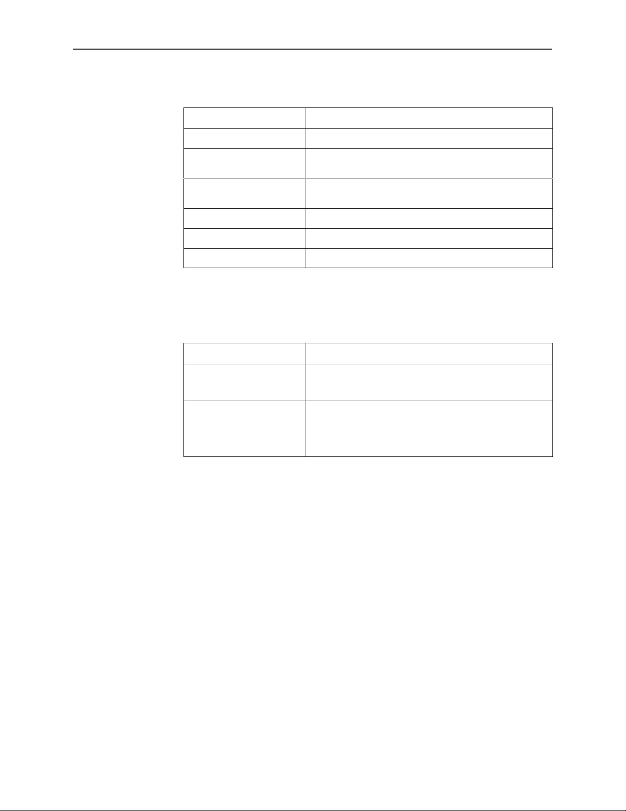
Table 4-4. Enterprise-Specific Trap Definitions
Monitoring and Testing
Trap Value
enterpriseClockFail(1) The currently configured master clock source has failed.
enterpriseSelfTestFail(2) A DSU/CSU hardware failure is detected at self-test. This
enterpriseDeviceFail(3) An internal DSU/CSU failure is detected by the operating
enterpriseTestStart(5) A test is initiated.
enterpriseConfigChange(6) A configuration option is changed.
enterpriseTestClear(105) A test is concluded.
Event
trap is generated after DSU/CSU initialization.
software.
Table 4-5. SNMP Trap per Interface
Interface
T1 Network Up = No alarm or test conditions.
Synchronous Data Port Up = No test conditions, the port is assigned to a network
T rap Meaning
Down = Alarm or test conditions.
interface, and both CTS and DSR are ON.
Down = Test conditions, the port is unassigned, or either
CTS or DSR is off.
3166-A2-GB20-10
November 1998
4-13
Page 80

Monitoring and Testing
Troubleshooting
The DSU/CSU is designed to provide you with trouble-free service. However,
Table 4-6 gives you some direction if a problem occurs.
For problems other than those listed in the table, please contact your service
representative.
Table 4-6. Troubleshooting (1 of 2)
Symptom
No power 1. The power module is not
Power-Up
Self-Test fails
Message LOS at
NET appears
Message OOF at
Net appears
Possible Cause Solutions
securely attached.
2. The wall receptacle has no
power.
The DSU/CSU has detected an
internal hardware failure.
1. Network cable problem.
2. No signal is being transmitted
at the far-end.
3. Facility problem.
1. Incompatible framing format
between the network and the
DSU/CSU.
2. Network cabling problem.
3. Facility problem.
1. Check the power module
attachment.
2. Check the wall receptacle
power by plugging in some
equipment that is known to be
working.
Contact your service
representative.
1. Check that the network cable
is securely attached at both
ends.
2. Check the far-end status.
3. Contact your facility provider.
1. Check that the framing format
for the network interface is
correct.
2. Check that the network cable
is securely attached at both
ends.
3. Contact your facility provider.
4-14
Message
Yellow at Net
appears
Message
AIS at Net
appears
Message EER at
Net appears
1. Network cable problem.
2. Far-end device has lost
framing sync on the line.
3. Facility problem.
1. Upstream device is
transmitting an AIS.
2. The network is transmitting
an AIS.
Facility problem. Contact your facility provider.
November 1998
1. Check that your network
cable is securely attached at
both ends.
2. Check the status of the
far-end device.
3. Contact your facility provider.
1. Check the status of the
upstream device(s).
2. Contact your facility provider.
3166-A2-GB20-10
Page 81
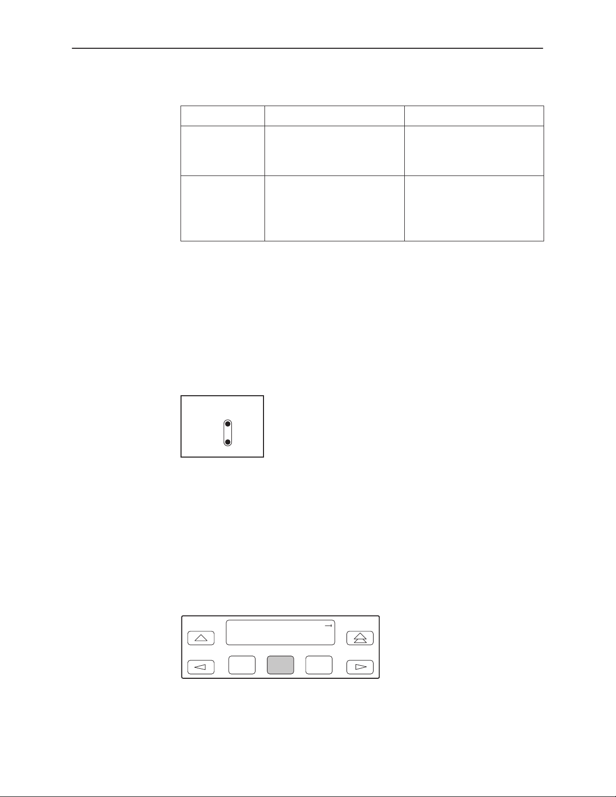
Table 4-6. Troubleshooting (2 of 2)
Symptom SolutionsPossible Cause
Monitoring and Testing
Test Jacks
A failure message
appears followed
by an 8-digit code
x x x x x x x x
(
Mgmt link is down 1. The manager configuration is
Internal DSU/CSU problem. Record the 8-digit code, then
contact your service
)
mismatched with the
DSU/CSU configuration.
2. The manager’s link layer
protocol is not running.
representative.
1. Check that the configurations
are matched.
2. Start the link layer protocol.
Two test jacks are located on the front panel: Net Mon (Network Monitor) In, and
Net Mon Out.
Net Mon In nonintrusively monitors the signal going into the network.
Net Mon Out nonintrusively monitors the signal coming from the network.
Net
Mon
In
Test Commands
Out
98-15942
The test commands enable you to run loopbacks and test patterns on the
DSU/CSU, and to test the front panel LEDs. These tests can help you isolate
areas of trouble if you are having problems with your DSU/CSU.
To access all Test commands from the Test branch, press F2 to select Test from
the top-level menu screen.
DSU ESF
Stat Test Cnfig
F1
F2
F3
3166-A2-GB20-10
November 1998
4-15
Page 82

Monitoring and Testing
Remote Loopback Tests
The Remote Loopback tests enable you to troubleshoot your circuit by sending
the following to a far-end device:
For Networks
Line loopback up activation sequence for 10 seconds (LLBUP)
Line loopback down activation sequence for 10 seconds (LLBDN)
For Channels
V.54 activation sequence to initiate a V.54 Loop 2 (54UP)
V.54 deactivation sequence to terminate a V.54 Loop (54DN)
ANSI T1.403 (Annex B) activation sequence to initiate a DCLB on the remote
device (FT1UP)
ANSI T1.403 (Annex B) deactivation sequence to terminate a DCLB on the
remote device (FT1DN)
You cannot perform remote loopbacks if any of the local loopbacks are active. If
you attempt to do so, the error message Invld Test Combo (Invalid Test
Combination) appears.
4-16
November 1998
3166-A2-GB20-10
Page 83
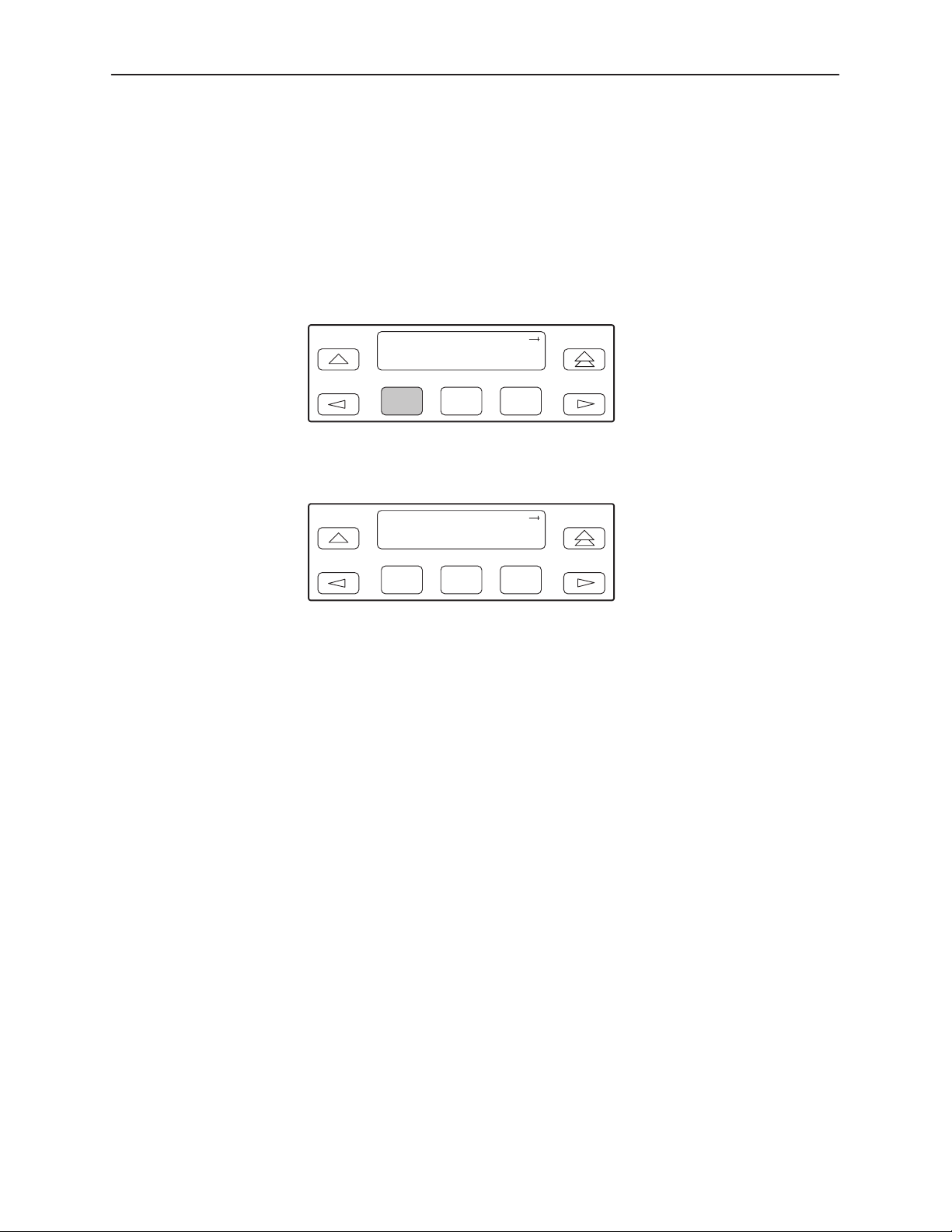
Sending a Line Loopback Up or Down
Procedure
To send a Line Loopback Up or Down sequence on the network to a far-end
DSU/CSU:
1. From the top-level menu screen, select Test.
2. From the Test screen, select Rlpbk.
Test:
Rlpbk Lpbk Ptrns
Monitoring and Testing
F1
F2
F3
3. From the Rem Loopback screen, press F1 to select LLBUP (Line Loopback
Up), or press F2 to select LLBDN (Line Loopback Down).
Rem Loopback:
LLBUP LLBDN 54UP
F1
F2
F3
The Line Loopback sequence is sent up or downstream to the far-end
DSU/CSU for 10 seconds. During this time, Sending appears on Line 2 of
the LCD, followed by Command Complete when 10 seconds have elapsed.
You can press any function key to restore the Rem Loopback screen without
affecting transmission of the loopback code.
3166-A2-GB20-10
November 1998
4-17
Page 84
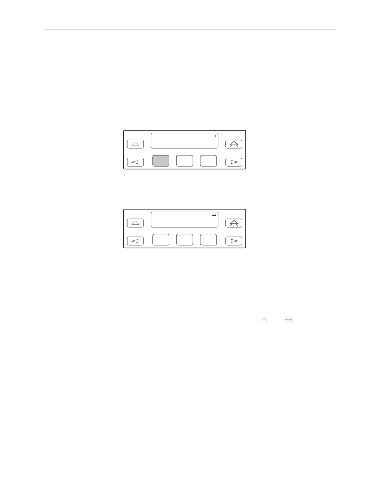
Monitoring and Testing
Sending a V.54/ANSI FT1 Activation/Deactivation
Procedure
To send a V.54 or ANSI FT1 Activation or Deactivation loopback sequence to the
far-end DSU/CSU:
1. From the top-level menu screen, select Test.
2. From the Test screen, select Rlpbk.
Test:
Rlpbk Lpbk Ptrns
F1
F2
F3
3. From the Rem Loopback screen, press the function key that corresponds to
the specific loopback test you want to perform. Use the scroll keys, if
necessary.
Rem Loopback:
LLBUP LLBDN 54UP
F1
F2
F3
The 54UP, 54DN, FT1UP, and FT1DN commands send the requested
sequence out the network interface on the DS0 channels allocated to Port 1.
4. From the Rem Loop screen, press the desired function key to select the
specific port. Use the scroll keys, if necessary.
After you select a port, the sequence is sent to the far-end DSU/CSU. During
this time, Sending appears on Line 2 of the LCD, followed by Command
Complete when the sequence is complete.
During the Sending message, you can press the
and keys without
affecting transmission of the loopback sequence.
4-18
November 1998
3166-A2-GB20-10
Page 85

Local Loopback Tests
The Local Loopback tests enable you to conduct circuit testing and fault isolation
for the digital line. The supported local loopback tests are:
Line Loopback (LLB)
Payload Loopback (PLB)
Repeater Loopback (RLB)
Data Channel Loopback (DCLB)
Data Terminal Loopback (DTLB)
The Line Loopback command can be activated and deactivated in response to
commands received over the network interface. The Network Interface
configuration option NET LLB controls whether the DSU/CSU responds to the
commands transmitted on the network interface to initiate LLBs (see Appendix C,
Configuration Options
The data port configuration option NET DCLB controls whether the DSU/CSU
responds to inband V.54 commands to initiate DCLB for that port (see
Appendix C,
).
Configuration Options
Monitoring and Testing
).
Local loopback tests can be aborted (Abort Command) at any time.
Local loopback tests cannot be run if send pattern or remote loopback tests are
active. In most cases local loopbacks cannot run with each other. Table 4-7
shows valid combinations of local loopbacks.
Table 4-7. Valid Loopback Combinations
LLB PLB RLB DCLB DTLB
LLB
PLB
RLB
DCLB
DTLB
NO NO YES NO YES
NO NO NO NO YES
YES NO NO NO YES
NO NO NO NO NO
YES YES YES NO NO
3166-A2-GB20-10
November 1998
4-19
Page 86
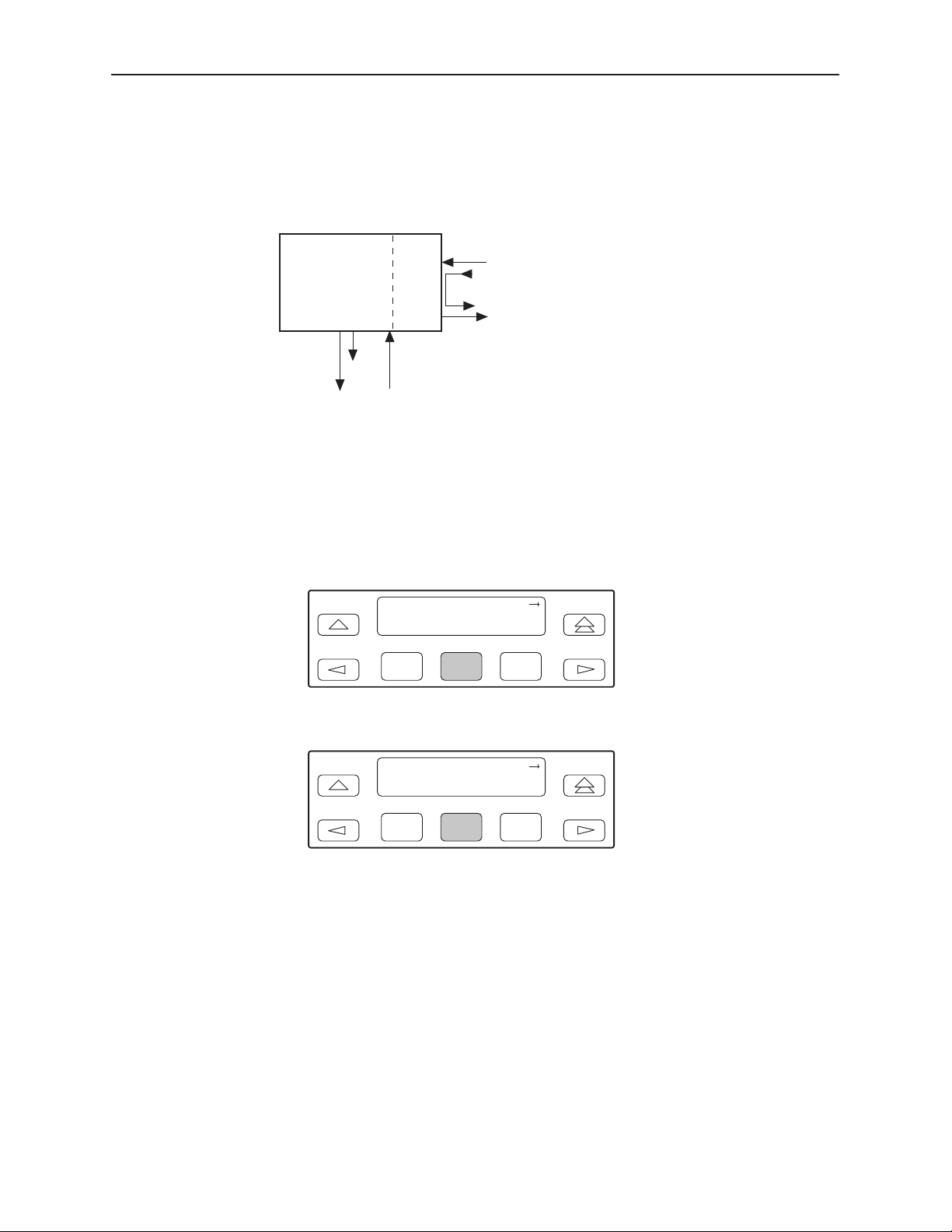
Monitoring and Testing
Starting a Line Loopback
The Line Loopback command (LLB) loops the received signal on the network
interface back to the network without change.
ALL 1s
CSUDSU
NETWORK
LLB
INTERFACE
PORT 1
98-15946
Procedure
To perform a Line loopback:
1. From the top-level menu screen, select Test.
2. From the Test screen, select Lpbk.
Test:
Rlpbk Lpbk Ptrns
F1
F2
3. From the Loopback screen, select LLB.
Loopback:
Abort LLB PLB
F1
F2
F3
F3
4-20
Test Started appears on Line 2. If a Line loopback is already in progress, the
Already Active message appears. If an invalid combination of loopbacks is
in progress, the error message Invld Test Combo appears (see Table 4-7 for
valid loopback test combinations).
November 1998
3166-A2-GB20-10
Page 87
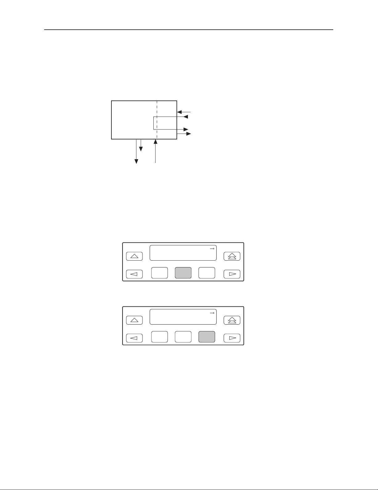
Starting a Payload Loopback
The Payload Loopback command (PLB) loops the received signal on the network
interface back to the network after it has passed through the framing circuitry of
the DSU/CSU. Framing CRCs and BPVs are corrected.
ALL 1s
Monitoring and Testing
CSUDSU
NETWORK
PLB
INTERFA CE
PORT 1
98-15947
Procedure
To perform a Payload loopback:
1. From the top-level menu screen, select Test.
2. From the Test screen, select Lpbk.
Test:
Rlpbk Lpbk Ptrns
F1
F2
3. From the Loopback screen, select PLB.
Loopback:
Abort LLB PLB
F1
F2
F3
F3
3166-A2-GB20-10
Test Started appears on Line 2. If a Payload loopback is already in progress,
the Already Active message appears. If an invalid combination of loopbacks
is in progress, the error message Invld Test Combo appears (see Table 4-7
for valid loopback test combinations).
November 1998
4-21
Page 88
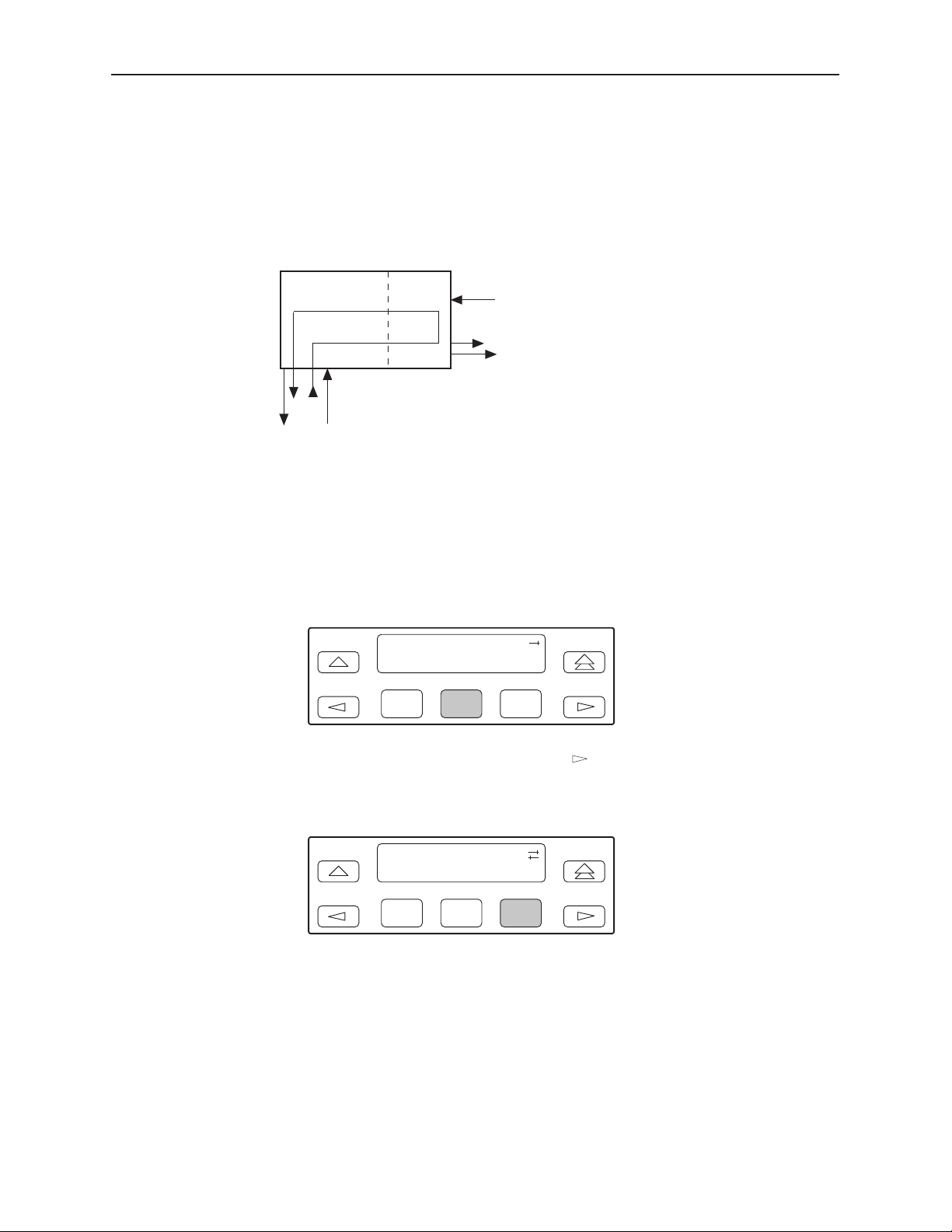
Monitoring and Testing
Starting a Repeater Loopback
The Repeater Loopback command (RLB) loops the signal being sent to the
network back to the data port. The signal is looped back as close to the network
interface as possible (after it has passed through the framing circuitry of the
DSU/CSU). Framing CRCs and BPVs are corrected.
CSUDSU
RLB
NETWORK
INTERFA CE
ALL 1s
PORT 1
98-15948
Procedure
To perform a Repeater loopback:
1. From the top-level menu screen, select Test.
2. From the Test screen, select Lpbk.
Test:
Rlpbk Lpbk Ptrns
F1
F2
3. From the Loopback screen, press the key until the RLB selection
appears on the screen.
4. Select RLB.
Loopback:
LLB PLB RLB
F3
4-22
F1
F2
F3
Test Started appears on Line 2. If a Repeater loopback is already in
progress, the Already Active message appears. If an invalid combination of
loopbacks is in progress, the error message Invld Test Combo appears (see
Table4-7 for valid loopback test combinations).
November 1998
3166-A2-GB20-10
Page 89
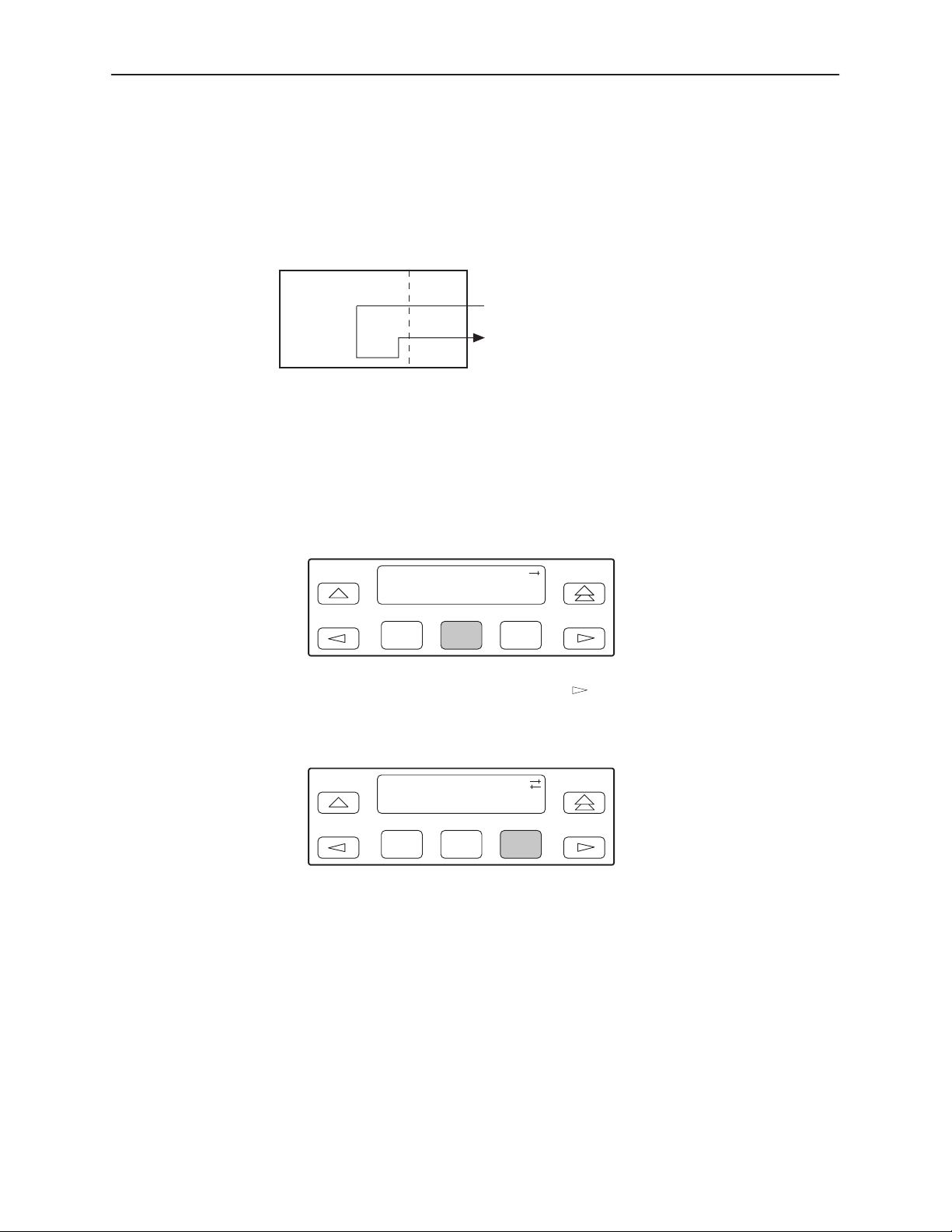
Starting a Data Channel Loopback
The Data Channel Loopback command (DCLB) loops the data received from the
network interface, for all DS0 channels allocated to Port 1, back to the network.
The loopback occurs after the data passes through the port circuitry but before it
is sent out the data port.
DCLB
Procedure
To perform a Data Channel loopback:
1. From the top-level menu screen, select Test.
Monitoring and Testing
CSUDSU
NETWORK
INTERFA CE
98-16103
2. From the Test screen, select Lpbk.
Test:
Rlpbk Lpbk Ptrns
F1
F2
F3
3. From the Loopback screen, press the key until the DCLB selection
appears on the screen.
4. Select DCLB.
Loopback:
PLB RLB DCLB
F1
F2
F3
Test Started appears on Line 2. If a Data Channel loopback is already in
progress, the Already Active message appears. If an invalid combination of
loopbacks is in progress, the error message Invld Test Combo appears (see
Table 4-7 for valid loopback test combinations).
3166-A2-GB20-10
November 1998
4-23
Page 90
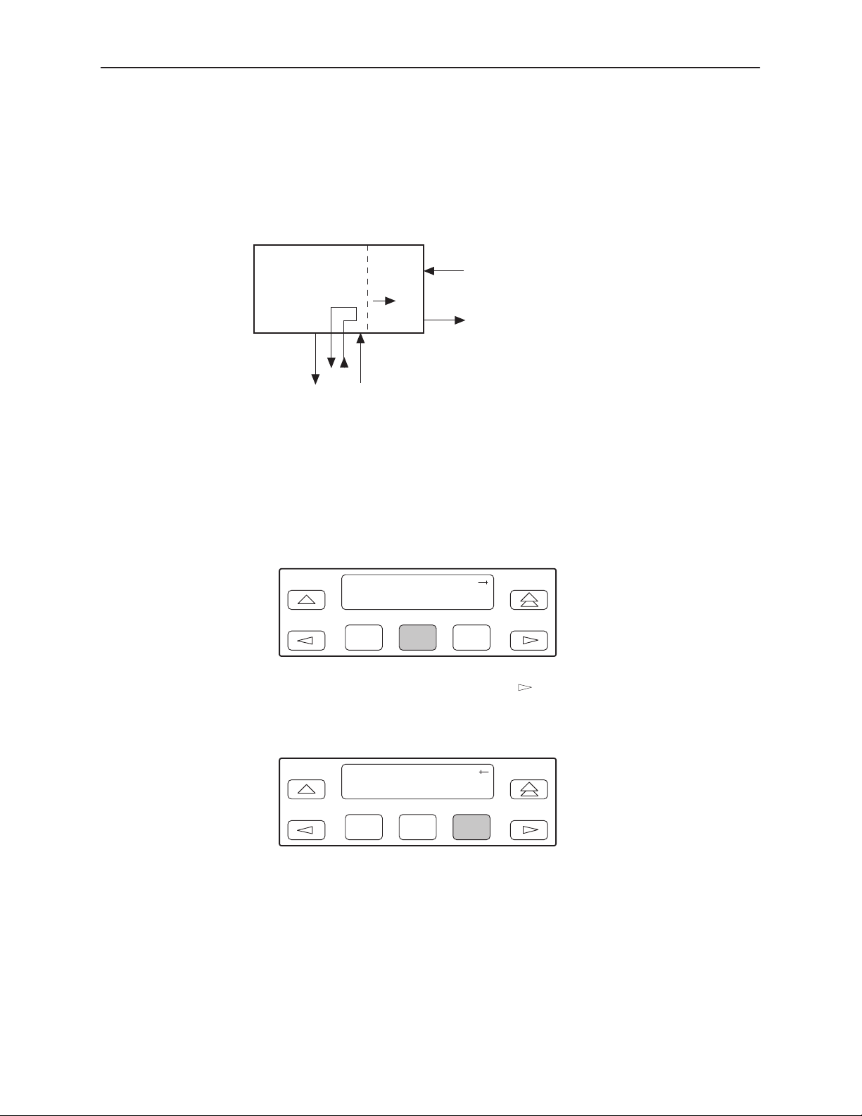
Monitoring and Testing
Starting a Data Terminal Loopback
The Data Terminal Loopback command (DTLB) loops the data received from
Port 1, for all DS0 channels allocated to the port, back out of the port. This
loopback occurs after the data passes through the port circuitry but before it
reaches the T1 framer.
CSUDSU
ALL 1s
DTLB
PORT 1
NETWORK
INTERFACE
98-15950
Procedure
To perform a Data Terminal loopback:
1. From the top-level menu screen, select Test.
2. From the Test screen, select Lpbk.
Test:
Rlpbk Lpbk Ptrns
F1
F2
3. From the Loopback screen, press the key until the DTLB selection
appears on the screen.
F3
4-24
4. Select DTLB.
Loopback:
RLB DCLB DTLB
F1
F2
F3
Test Started appears on Line 2. If a Data Terminal loopback is already in
progress, the Already Active message appears. If an invalid combination of
loopbacks is in progress, the error message Invld Test Combo appears (see
Table 4-7 for valid loopback test combinations).
November 1998
3166-A2-GB20-10
Page 91
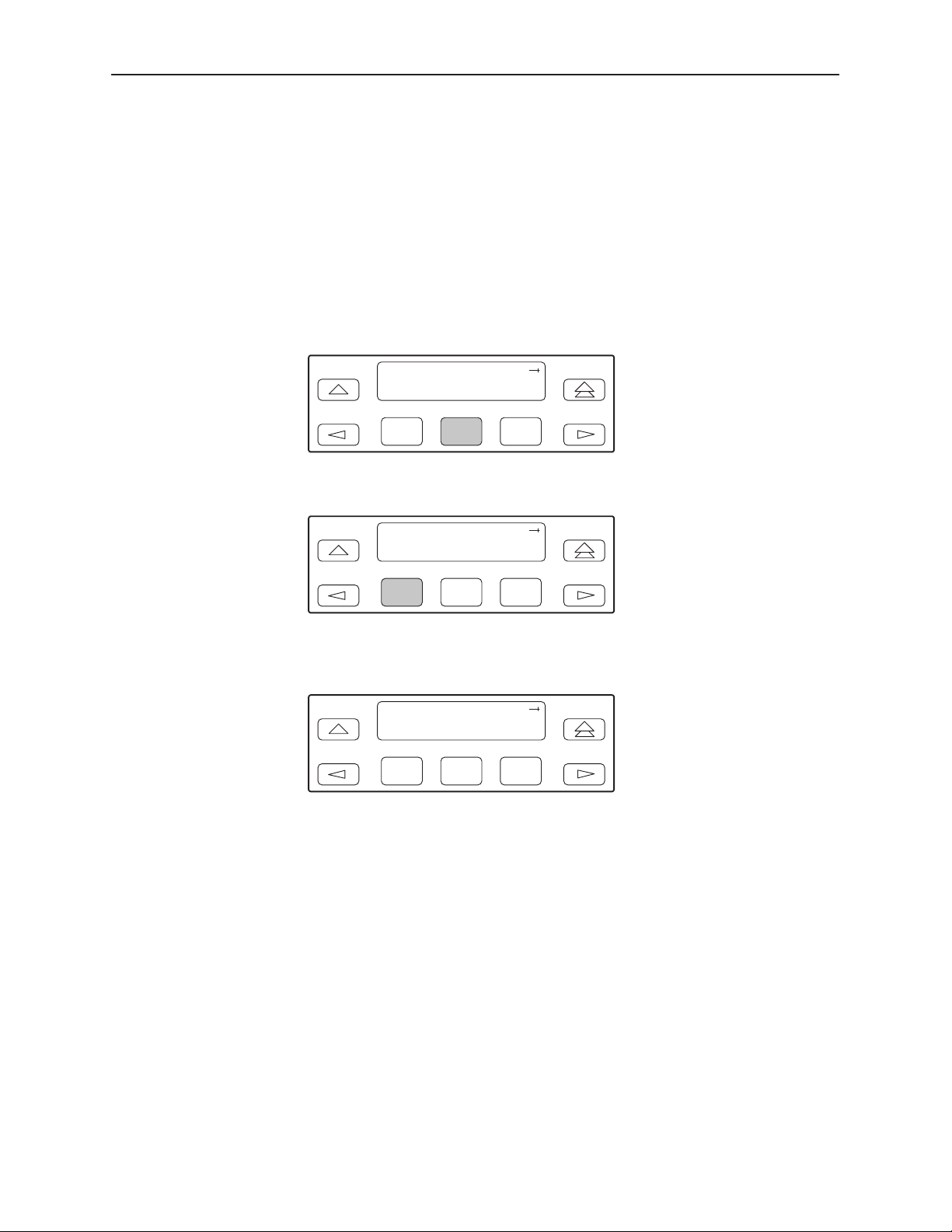
Aborting Loopbacks
Procedure
Monitoring and Testing
The Abort Loopback command stops all loopback tests or any selected loopback
test currently active on the DSU/CSU.
To abort one or more loopback tests:
1. From the top-level menu screen, select Test.
2. From the Test screen, select Lpbk.
Test:
Rlpbk Lpbk Ptrns
F1
F2
F3
3. From the Loopback screen, select Abort.
Loopback:
Abort LLB PLB
F1
F2
F3
4. From the Loopback Abort screen, press the desired Function key to abort All
or one specific loopback test. Use the scroll keys, if necessary.
Loopback: Abort
All LLB PLB
F1
F2
F3
When abort is complete, the message Command Complete appears on the
Abort screen.
3166-A2-GB20-10
NOTE:
If you mistakenly choose to abort a loopback test that is not currently running,
a Command Complete message will still display and the loopback that is
currently active will still be running. Use the TStat branch to view the test
status to determine if the abort was successful.
November 1998
4-25
Page 92
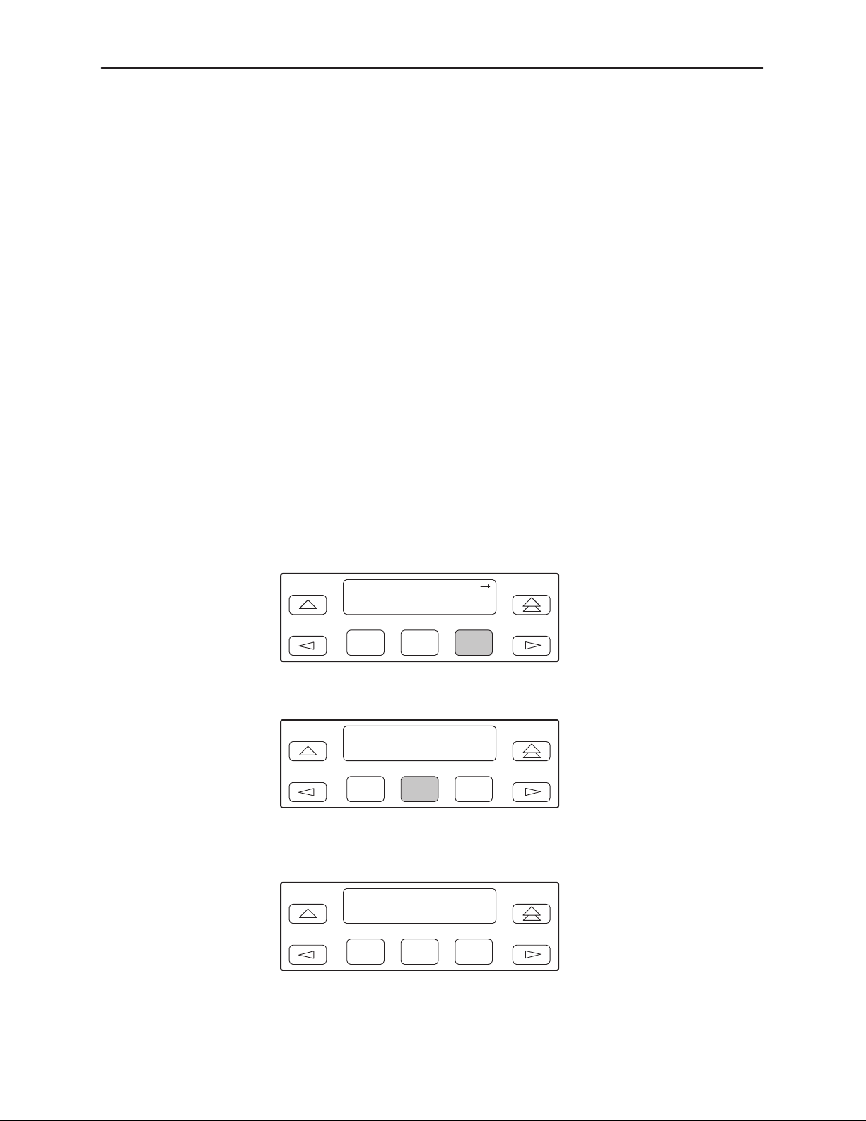
Monitoring and Testing
Test Patterns
Use the Test Pattern commands to send, monitor, and abort test patterns.
Available test patterns are:
H QRSS – A quasi-random signal source approximating live data that can be
monitored for logic errors (on the network and the data ports).
H 1-in-8 – A test pattern consisting of a one (1) followed by seven zeros (on the
network only).
Sending Test Patterns
" Procedure
H 511 – A pseudo-random bit sequence (PRBS) that is 511 bits long (on the
9
data ports only). This is a PRBS 2
–1 test.
Use the Send command to start transmission of a test pattern.
Only one test pattern can be active at a time.
To send a test pattern:
1. From the top-level menu screen, select Test.
2. From the Test screen, select Ptrns.
Test:
Rlpbk Lpbk Ptrns
F1
F2
F3
3. From the Patterns screen, select Send.
4-26
Patterns:
Abort Send Mon
F1
F2
F3
4. From the Patterns Send screen, press F1 to send a QRSS pattern, F2 to
send a 1-in-8 pattern, F3 to send a 511 pattern.
Patterns: Send
QRSS 1in8 511
F1
F2
F3
If you send a 1-in-8 pattern, skip Step 5.
November 1998
3166-A2-GB20-10
Page 93
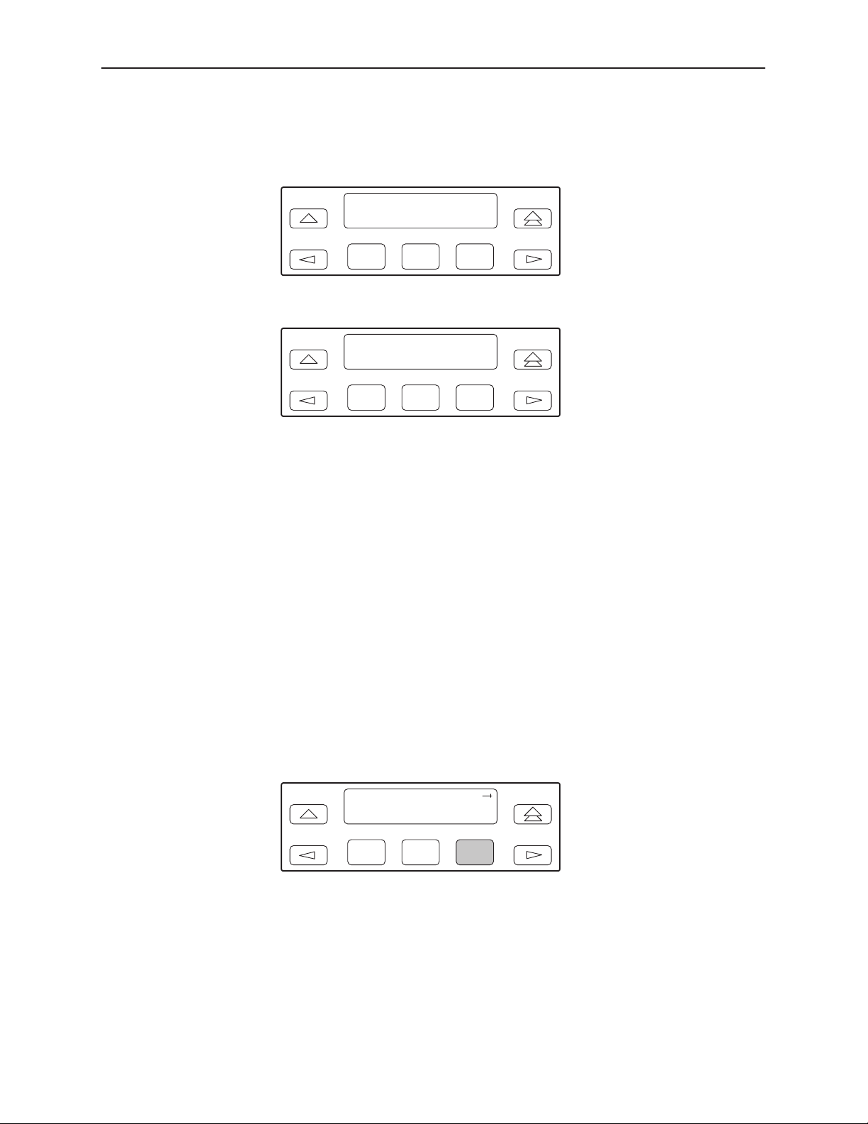
Monitoring and Testing
5. From the Send screen, press the Function key that corresponds to the
interface for which you want to send a test pattern. (NET does not appear for
the 511 pattern.)
Monitoring Test Patterns
Use the Monitor command to monitor a QRSS test pattern over all the channels
on the network interface, or to monitor QRSS or 511 test patterns on the channels
allocated to an individual port.
Send:
Name
NET Prt1
F1
F2
F3
The Test Started screen appears.
Send:
Name and Dest
Test Started
F1
F2
F3
If the DSU/CSU is already sending the test pattern you selected, the
message Already active appears. If you select a different pattern than one
the DSU/CSU is already sending, the message Invld Test Combo appears.
This command provides the number of errors detected in the test pattern
(5 digits, maximum 99999).
Procedure
To monitor a QRSS or 511 test pattern:
1. From the top-level menu screen, select Test.
2. From the Test screen, select Ptrns.
Test:
Rlpbk Lpbk Ptrns
F1
F2
F3
3166-A2-GB20-10
November 1998
4-27
Page 94
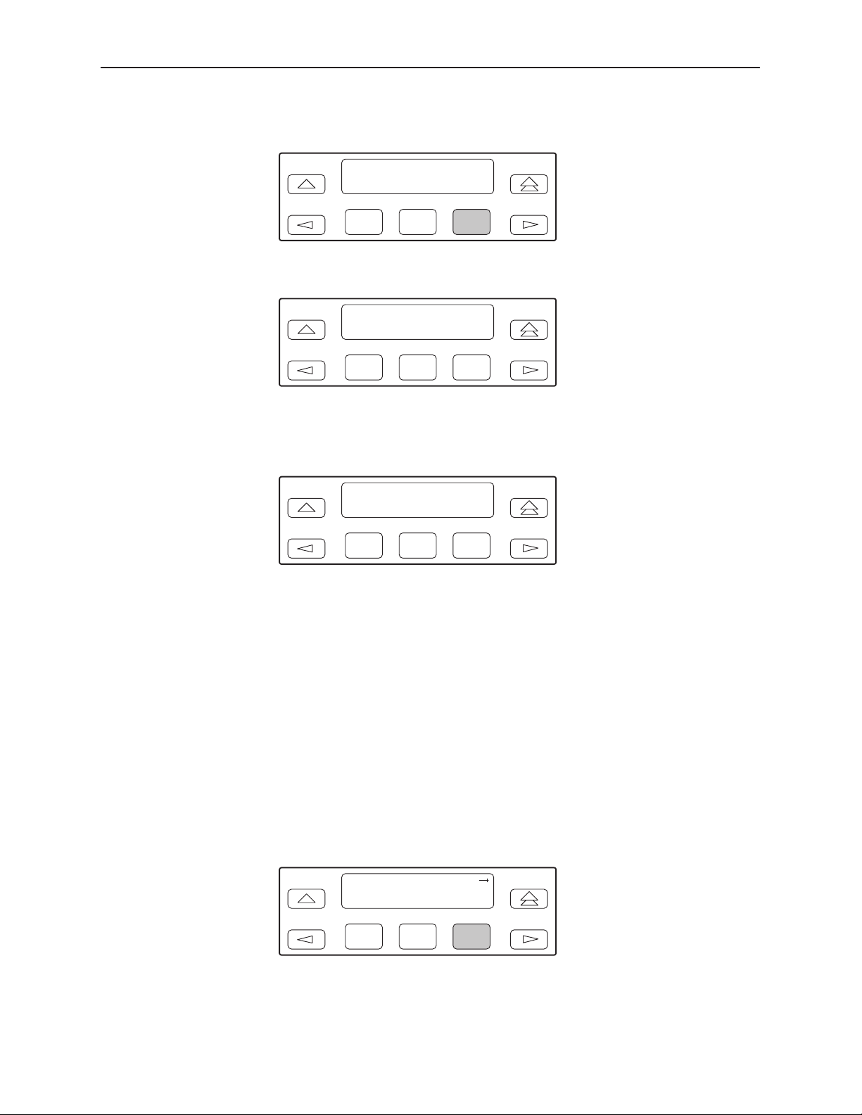
Monitoring and Testing
3. From the Patterns screen, select Mon.
Patterns:
Abort Send Mon
F1
F2
F3
4. From the Patterns Mon screen, press F1 for QRSS or F2 for 511.
Patterns: Mon
QRSS 511
F1
F2
F3
5. From the Monitor screen, press the Function key that corresponds to the
interface for which you want to send a test pattern. (NET does not appear for
the 511 pattern.)
Monitor:
Name
NET Prt1
F1
F2
F3
The Monitor screen appears with the error count. If the maximum of 99999 is
exceeded, OvrFlw appears instead of the count. If the receiver loses
synchronization while the monitor is active, No Sync appears.
Aborting Test Patterns
Procedure
4-28
Use the Abort command to stop all test patterns or any selected test pattern
active on the DSU/CSU.
To abort test patterns:
1. From the top-level menu screen, select Test.
2. From the Test screen, select Ptrns.
Test:
Rlpbk Lpbk Ptrns
F1
November 1998
F2
F3
3166-A2-GB20-10
Page 95
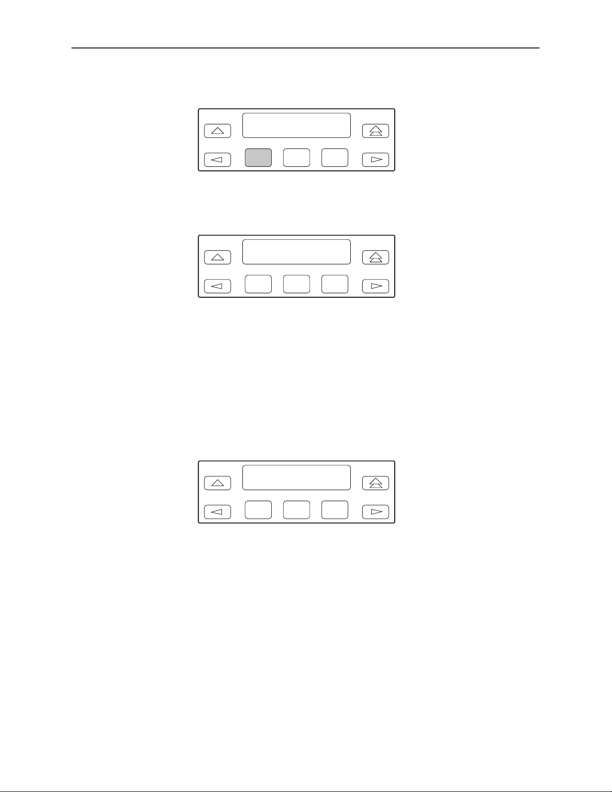
3. From the Patterns screen, select Abort.
Patterns:
Abort Send Mon
Monitoring and Testing
F1
F2
F3
4. From the Patterns Abort screen, press the desired Function key to abort
either All active test patterns, active Send test patterns, or the active Monitor
(Mon) test pattern.
Patterns: Abort
All Send Mon
F1
F2
F3
If you select All, the DSU/CSU terminates all active test patterns and displays
the message Command Complete. Skip Step 5.
NOTE:
If you mistakenly choose to abort a test pattern that is not currently
running, a Command Complete message still displays and the test
pattern currently active still runs. Use the TStat branch to view the test
status to determine if the abort was successful.
5. From the Abort screen, press the Function key that corresponds to the
interface for which you want to abort a test pattern. Use the scroll keys, if
necessary.
3166-A2-GB20-10
Abort:
Send or Mon
NET Prt1
F1
F2
F3
The DSU/CSU terminates the selected test pattern and displays the message
Command Complete.
November 1998
4-29
Page 96
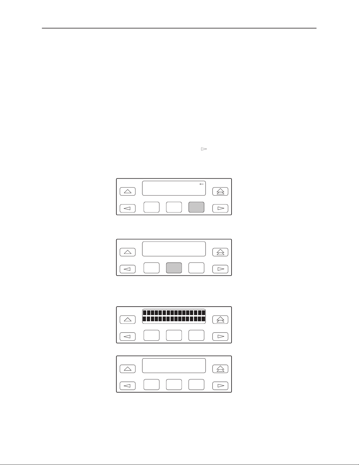
Monitoring and Testing
Lamp Test
Starting a Lamp Test
Use the Lamp Test commands to start and stop a test of the DSU/CSU front
panel LCD and LEDs.
Procedure
To start a Lamp test:
1. From the top-level menu screen, select Test.
2. From the Test screen, press the
key until the Lamp selection appears on
the screen.
3. From the Test screen, select Lamp.
Test:
Lpbk Ptrns Lamp
F1
F2
F3
4. From the Lamp Test screen, select Start.
Lamp Test:
Abort Start
F1
F2
F3
5. The following screens alternately appear on the LCD until you press a
Function key to return to the Lamp Test screen. In addition, all LEDs blink.
4-30
F1 F2
F3
0123456789 : ; < = > ?
@ABCDEFGHIJKLMNO
F1
November 1998
F2
F3
3166-A2-GB20-10
Page 97
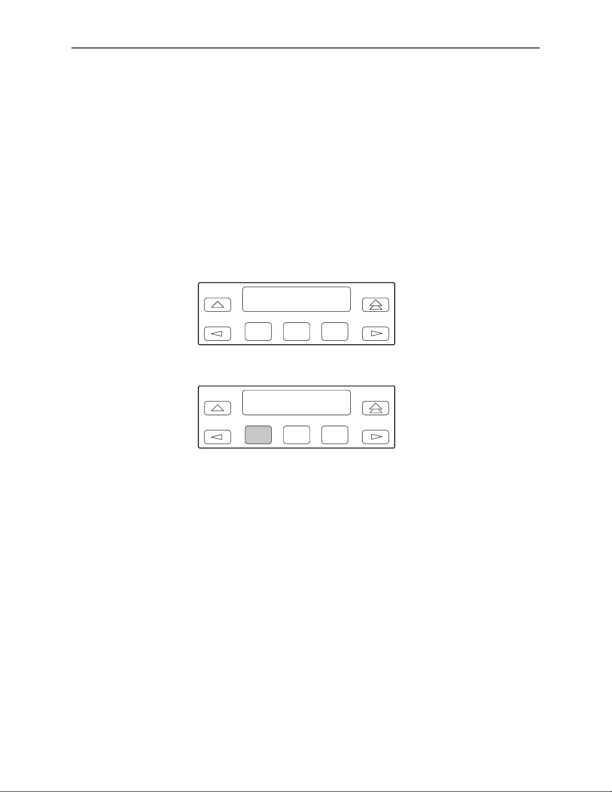
Aborting a Lamp Test
Monitoring and Testing
6. When you are satisfied that all LEDs are lighting and the LCD is functioning
properly, abort the Lamp test from the Lamp Test screen. If there is no activity
on the DSU/CSU front panel for five minutes, the Device Health and Status
screen appears automatically. However, the Lamp test remains active until it
is aborted.
Procedure
To abort the Lamp test:
1. Display the Lamp Test screen. To do this when the LCD is alternating the
Lamp test screens, press any Function key. Otherwise, follow Steps 1
through 3 of
Starting a Lamp Test
Lamp Test:
Abort Start
on page 4-30.
F1
F2
F3
2. From the Lamp Test screen, select Abort.
Lamp Test:
Abort Start
F1
F2
F3
3166-A2-GB20-10
November 1998
4-31
Page 98
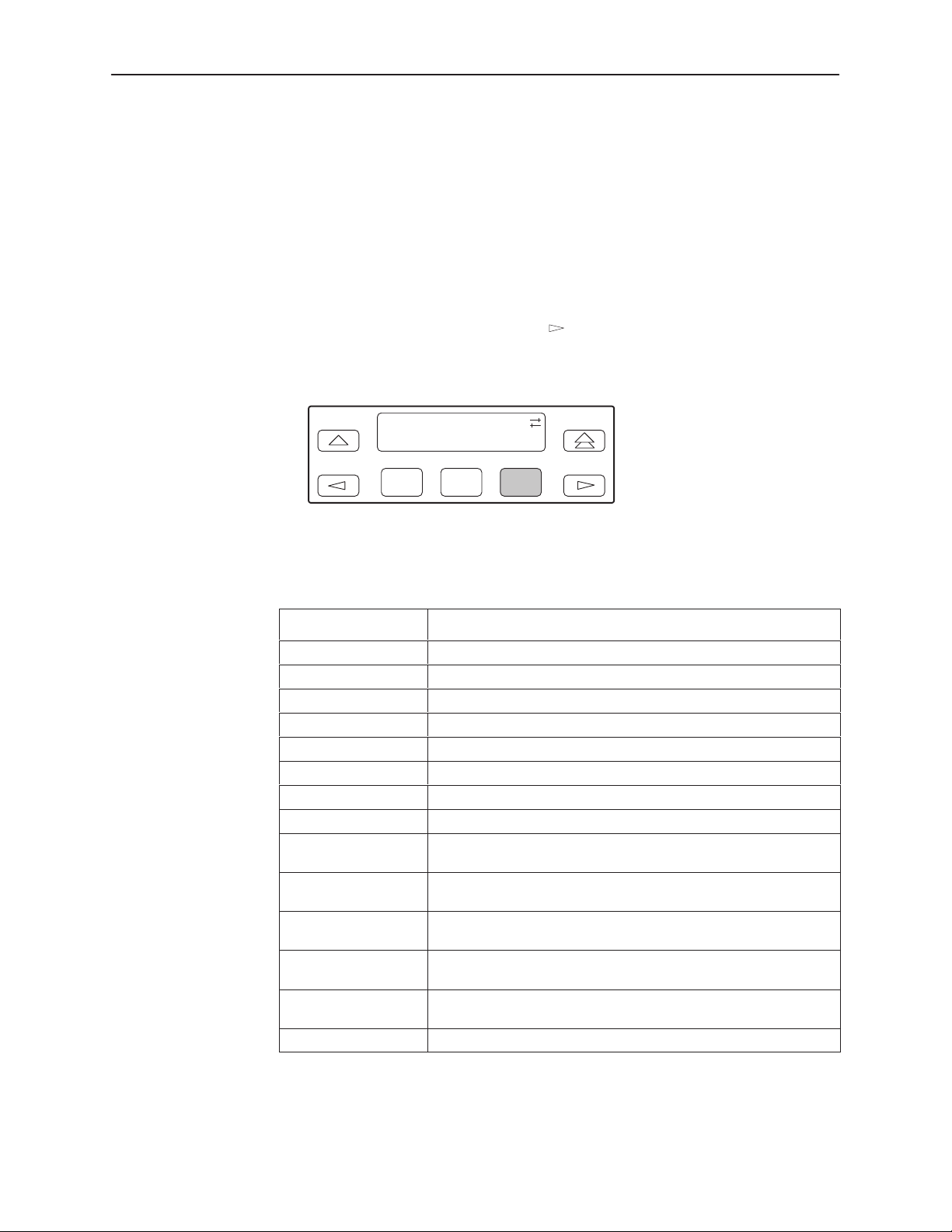
Monitoring and Testing
Displaying DSU/CSU Test Status
Use the Test Status command to display the active tests for the DSU/CSU. Status
messages that can display on the front panel LCD are listed in Table 4-8.
Procedure
To display test status:
1. From the top-level menu screen, select Stat.
2. From the Status screen, press the
key until the TStat selection appears
on the screen.
3. Select TStat.
Status:
STest Perf TStat
F1
F2
F3
The Test Status screen appears showing you what tests are active for the
DSU/CSU.
Table 4-8. Test Status Message
Message
No Test Active No tests are currently active.
LLB Test Active The network interface is in Line loopback.
PLB Test Active The network interface is in Payload loopback.
RLB Test Active Port 1 is in Repeater loopback.
DCLB on Port 1 Port 1 is in a Data Channel loopback.
DTLB on Port 1 Port 1 is in a Data Terminal loopback.
QRSS on Net A QRSS test pattern is being sent on the network interface.
1–8 Test Active A 1-in-8 test pattern is being sent on the network interface.
QRSS on Port 1 A QRSS test pattern is being sent to the network on the
511 on Port 1 A 511 test pattern is being sent to the network on the channels
Mon QRSS, Net A QRSS test pattern is being monitored on the network
Mon QRSS, Port 1 A QRSS test pattern is being monitored on the channels
Mon 511, Port 1 A 511 test pattern is being monitored on the channels allocated
Lamp Test Active The Lamp test is currently active.
Description
channels allocated to Port 1.
allocated to Port 1.
interface.
allocated to Port 1.
to Port 1.
4-32
November 1998
3166-A2-GB20-10
Page 99
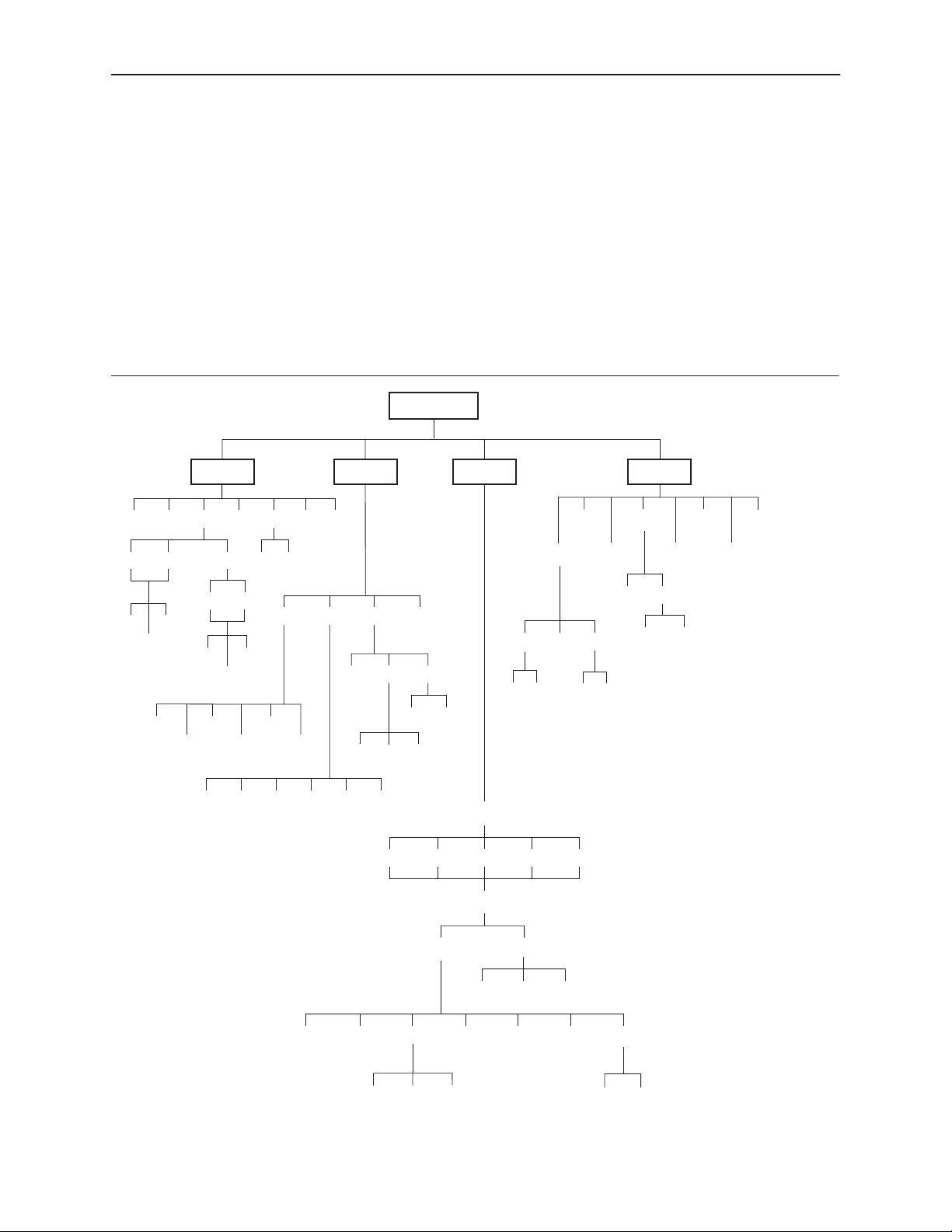
SDCP Menu
A
DSU ESF
Stat
DevHS
STest Perf TStat LED ID
Cur
Intvl
24Tot
LLBUP
Cur
8Tot
54UP
LLBDN
Clear*
T1 Prt1Prt1UserTelco
FarNear
Rlpbk Lpbk Ptrns Lamp
Intvl
Abort Mon
FT1UP
54DN
FT1DN
PLB RLBLLBAbort DCLB DTLB
Test
Send
QRSS 511
QRSS 1in8 511
Activ Cust1 Cust2 Fact1 Fact2
Cnfig Ctrl
1 . . 5,A
(Directory)
Load Edit Area From:
Choose Function:
ACO
Call
DiscDial ChDir
1 . . 5,A
(Directory)
ClrReg
Rel
User Prt1
Reset
FarNear
CID
DL
Passwd
* Available only if a device
failure has occured.
3166-A2-GB20-10
Edit
Prt1ClearDsply
November 1998
Save
Cust1Activ Cust2
User AlarmNETPrt1 Chan Gen Mgmt
Gen Trap
98-16084a-01
A-1
Page 100

SDCP Menu
This page intentionally left blank.
A-2
3166-A2-GB20-10November 1998
 Loading...