


 Loading...
EVO48
EVO192
User Guide
We hope this product performs to your complete satisfaction. Should you have any questions or comments, please visit www.paradox.com and send us your comments.

Table of Contents
Introduction ....................................... |
2 |
Legend .............................................................. |
2 |
Basic Operation ................................. |
3 |
Confidential Mode ............................................. |
4 |
MG-REM2 Feedback .......................... |
5 |
Full/Force Arming Indicators ............................. |
5 |
Stay/Sleep Arming Indicators ............................ |
5 |
Other Indicators ................................................ |
5 |
Partitioned System ............................ |
6 |
Area Display ...................................................... |
6 |
Arming ................................................ |
7 |
Exit Delay Timer ................................................ |
7 |
Regular Arming ................................................. |
7 |
Stay Arming ...................................................... |
7 |
Instant Arming ................................................... |
7 |
Force Arming .................................................... |
7 |
Bypass Programming ........................................ |
7 |
Keyswitch Arming ............................................. |
8 |
Auto-Arming ...................................................... |
9 |
Disarming ......................................... |
10 |
Entry Delay Timer ........................................... |
10 |
Disarming an Armed System .......................... |
10 |
Alarm Memory Display .................................... |
10 |
Access Codes .................................. |
11 |
System Master Code (Default 123456) ........... |
11 |
Copy User Options .......................................... |
11 |
User Labels ..................................................... |
11 |
Deleting User Access Codes .......................... |
13 |
Programming User Access Codes .................. |
13 |
User Options ................................................... |
15 |
Access Control User Options .......................... |
15 |
Using Access Control ..................... |
17 |
Entering & Exiting ........................................... |
17 |
Arming and Disarming with Card .................... |
17 |
How Access Control Works ............................ |
18 |
Trouble Display ............................... |
19 |
Trouble Display ............................................... |
19 |
Event Record Display ..................................... |
20 |
Additional Features ......................... |
21 |
Programmable Outputs (PGMs) ..................... |
21 |
Keypad Settings .............................................. |
21 |
Modifying illumination settings on the DGP2-648BL LED
21 |
|
Setting Time & Date ........................................ |
21 |
Programming Chime Zones ............................ |
22 |
Panic Alarms ................................................... |
22 |
Quick Function Buttons ................................... |
22 |
VDMP3 Plug-In Voice Dialer ........... |
23 |
Calling the VDMP3 (outside line) .................... |
23 |
Receiving a Call From the VDMP3 (alarm in system) 23
Testing and Maintenance ............... |
25 |
Burglar Alarm Testing ..................................... |
25 |
Fire Alarm Testing ........................................... |
25 |
System Maintenance ...................................... |
25 |
System Test .................................................... |
25 |
Fire and Burglar Alarms ................. |
26 |
Standard Fire Zone ......................................... |
26 |
Delayed Fire Zone .......................................... |
26 |
Fire Safety Tips ............................................... |
26 |
Minimizing Home Fire Hazards ....................... |
27 |
Home Fire Warning System ............................ |
27 |
Burglar Alarm .................................................. |
27 |
Appendix 1: Hebrew Special Characters ........ |
28 |
Appendix 2: Russian Special Characters ........ |
29 |
Appendix 3: Greek Special Characters ........... |
30 |
Index ................................................. |
31 |
1.0 Introduction
Your EVO System is an advanced technology security system that will provide you with reliable security protection and powerful features that are easy to use. The elegant and user-friendly keypads will allow you easy access to your security system's functions and information at the touch of a button.
Messages will be displayed differently depending on the keypad you have selected.The 32-character screen on LCD keypads will display messages and menus to guide you through the system’s operations. Your installer can even customize the messages on LCD keypads for your home or business.The LED display of the DGP2-648BL will let you assess the system status at a glance.
Since you will communicate your instructions to your system through the keypad, please read this manual carefully and have your installer explain basic system operation.
1.1Legend
Indicates a warning or an important note.
Indicates useful information or a tip.
[TEXT] Indicates information that must be entered on the keypad.
LCD Indicates an LCD Keypad instruction or information.
LED |
Indicates a DGP2-648BL instruction or information. |
|
|
2 User Guide

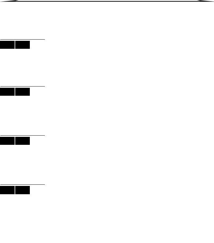
2.0 Basic Operation
The following sections will introduce you to the functions of the buttons, lights, and messages on your keypad.
Figure 1: LCD Keypad Basic Overview
AC Light: |
|
ON |
= AC power |
OFF |
= Power failure |
STATUS Light:
When Green:
ON |
= All zones are closed. |
OFF |
= One or more zones are |
open. |
|
FLASH |
= Exit Delay in progress |
When Red: |
|
ON |
= Area(s) armed |
OFF |
= Area(s) disarmed |
The LCD screen will guide you with detailed messages.
Use the arrow buttons to scroll through the current menu when the arrows appear in the LCD screen.
Figure 2: DGP2-648BL LED Keypad Overview
AC Light: |
|
ON |
= AC Power (OK) |
OFF |
= Power failure |
AREA Lights: (A1, A2, A3 and A4) |
|
ON |
= Area armed |
OFF |
= Area disarmed |
FLASH |
= Area in alarm |
STATUS Light:
When green:
ON |
= All zones closed |
OFF |
= One or more zones are |
open |
|
FLASH |
= Exit Delay in progress |
When red: |
|
ON |
= Area(s) armed |
OFF |
= Area(s) disarmed |
FLASH |
= System in Alarm |
The keypad will display the status of all its assigned areas.
ACTION Lights: (Access, Stay, Force, Byp, Mem, Trbl and Prg) Lights will illuminate according to the status of the system.
Numerical Lights: (Zones)
ON |
= Zone is open |
OFF |
= Zone is closed (OK) |
FLASHES |
= Zone / fire loop |
For all keypads, the [ENTER] key will save and exit, and the [CLEAR] key will exit without saving. [ENTER] and [CLEAR] represent the LCD/LED keypads’ enter and clear keys unless both keys are shown to have a different function.
EVO Systems 3
LCD LED
LCD LED
2.1 Auditory Feedback (Beep Tones)
When you enter information on the keypad, the keypad will guide you with beep tones to communicate the acceptance or rejection of your entries.
Confirmation Beep: When an operation (i.e. arming/disarming) is successfully entered or when the system switches to a new status/mode, the keypad emits an intermittent beep tone (“BEEP-BEEP-BEEP-BEEP-BEEP”).
Rejection Beep: When the system reverts to a previous status, or when an operation is incorrectly entered, the keypad emits a continuous beep tone (“BEEEEEEEEEEP”).
2.2Confidential Mode
Your installer can program keypads to not display the status of your system automatically by changing the keypad to Confidential Mode.
In Confidential Mode:
•The zones and status messages will NOT be displayed
•The indicator lights will NOT illuminate
•Depending on how your keypad was programmed by your installer, you must either press a button or enter your user access code to illuminate the indicator lights and activate Normal Mode.
4 User Guide

3.0 MG-REM2 Feedback
If your system includes the Wireless Zone Expansion module (MG-RTX3), it will be able to support the Two-Way Remote Control (MG-REM2). This remote allows you to change the status of the system, and it also provides visual and auditory feedback.
3.1Full/Force Arming Indicators
Action |
LED Sequence |
Auditory Sequence |
|
|
|
Disarming |
Green on |
Two beeps |
|
|
|
Exit delay |
Red / green slow flash |
Confirmation beep |
|
|
|
Arming / Entry Delay |
Red on |
Confirmation beep |
|
|
|
Alarm |
Red fast flash |
Alarm beep |
|
|
|
3.2Stay/Sleep Arming Indicators
Action |
LED Sequence |
Auditory Sequence |
|
|
|
Disarming |
Green on |
Two beeps |
|
|
|
Exit delay |
Yellow / green slow flash |
Confirmation beep |
|
|
|
Arming / Entry Delay |
Yellow on |
Confirmation beep |
|
|
|
Alarm |
Red fast flash |
Alarm beep |
|
|
|
3.3Other Indicators
Action |
LED Sequence |
Auditory Sequence |
|
|
|
PGM on/off |
Yellow on |
Confirmation beep |
|
|
|
EVO Systems 5

4.0 Partitioned System
Your installer can set your keypad to recognize separate protected areas. A separated system is called a partitioned system, which can be useful in situations where shared security systems are more practical. For example, a company that has both an office and a warehouse area, can arm and disarm each area separately while controlling access to each area. Therefore, one person may have access to only one area, whereas another person may have access to all areas. Access to the areas is determined by the User Access Code.
LCD
LED
4.1Area Display
The Area Status Display enables you to see the status of the individual areas within a partitioned system. Your installer can partition the system into separate areas.
To view the status of the areas:
1.Enter your [ACCESS CODE], and then press the [1] button.
2.Press the button corresponding to the area (i.e. 1, 2,...8), or use the [S] and [T] buttons and press [ENTER] when the area you want to view appears on the screen.
3.Press [CLEAR] to exit.
In Area Status Display mode, the following information will scroll on the LCD screen:
•ready: if all zones in the selected area are closed.
•not ready: if zones in the selected area are open.
•Front Door Open: if there is an open zone within that area.
•Trouble(s): (section 9.0 on page 19) if a trouble has occurred.
•Alarms in Memory: (section 6.3 on page 10) if an alarm has occurred.
•Armed; Force Armed; Instant Armed; Stay Armed: displays the arming status of the selected area.
In Area Status Display, the following will illuminate for the area selected:
•The area lights (A1, A2, A3, and A4) if the associated area is armed. For example, if you have selected area 3 and it is currently armed, A3 will illuminate.
•The numerical light(s) representing any open zone(s) in a corresponding area or areas.
•The MEM action light if any alarms have occurred.
•The TRBL action light if any troubles are occurring.
•The STAY action light if the area is Stay or Instant Armed.
•The FORCE action light if the area is Force Armed.
•The BYP action light if zones are bypassed.
6 User Guide
5.0 Arming
When your system is armed, it can respond to any breach in the protected zones by causing an alarm and sending a report to your monitoring station.
|
|
5.1 Exit Delay Timer |
LCD LED |
|
|
|
When you arm your system, it will trigger the Exit Delay Timer to provide you with enough |
|
|
|
|
|
|
time to exit the protected area before the system is armed. |
LCD LED
LCD LED
LCD LED
LCD LED
5.2Regular Arming
This method is used for the everyday arming of your system. All zones within the protected area must be closed to Regular arm the system.
To Regular arm the system:
1.Enter your [ACCESS CODE].
2.Press the [ARM] button.
3.If you have access to more than one area, select the area(s) you wish to Regular arm (refer to section 4.1 on page 6).
5.3Stay Arming
Stay arming will partially arm your system to permit you to remain in your home or office by arming the outer zones (perimeter) of the protected area (i.e. doors and windows).
To Stay arm:
1.Enter your [ACCESS CODE].
2.Press the [STAY] button.
3.If you have access to more than one area, select the area(s) you wish to Stay arm (refer to section 4.1 on page 6).
5.4Instant Arming
This feature is the same as Stay arming except that there is no Entry Delay. Therefore, any armed zone that is breached will immediately generate an alarm.
To Instant arm:
1.Enter your [ACCESS CODE].
2.Press the [5] button.
3.If you have access to more than one area, select the area(s) you wish to Instant arm (refer to section 4.1 on page 6).
5.5Force Arming
Force arming allows you to quickly arm your system when zones are open. However, once the open zone is closed, your system will then arm that zone as well.
To Force arm:
1.Enter your [ACCESS CODE].
2.Press the [FORCE] button.
3.If you have access to more than one area, select the area(s) you wish to Force arm (refer to section 4.1 on page 6).
|
|
5.6 Bypass Programming |
LCD LED |
|
|
|
You can bypass certain zones when you arm the protected area(s). When a zone is |
|
|
|
|
|
|
bypassed, it will be ignored the next time your system is armed. Once your area is |
|
|
disarmed, the system will unbypass the zone. |
To Bypass a zone:
1.Enter your [ACCESS CODE].
2.Press the [BYP] button.
EVO Systems 7

LCD LED
LCD LED
3.Enter the zone number (i.e. 01, 02,...96), or use the [S] and [T] buttons and press [BYP] once the zone you want to bypass appears on the screen. If bypassed, the byp light does not appear on the screen and the keypad emits a rejection beep, you may not have access to bypass that zone.
4.Repeat step 3 until all zones you want to bypass have been selected.
5.Press the [ENTER] button to save and exit.
To view all bypassed zones.
1.Enter your [ACCESS CODE].
2.Press the [BYP] button.
3.Scroll through the zones using the [S] and [T] buttons to view zone status. (LCD Keypads)
In order to bypass a zone, the following conditions must be met:
•The zone must have the Bypass option programmed by your installer.
•The Bypass option must be enabled in your User Options.
•Your user access code must have access to the zone’s Area Assignment.
•The zone’s area must be disarmed before the zone can be bypassed.
Fire Zones cannot be bypassed.
5.6.1Bypass Recall
Bypass Recall reinstates the zones that were bypassed the last time your system was armed.
To activate Bypass Recall:
1.Enter your [ACCESS CODE].
2.Press the [BYP] button.
3.Press the [MEM] button.
Zones bypassed the last time your system was armed are bypassed.
4.Press the [ENTER] button to save and exit.
5.6.2One-Touch Buttons
If enabled by your installer, you can access the following features without using your user access code by pressing and holding the desired One-Touch button.
|
Table 1: One Touch Button |
Button |
Feature |
[ARM] |
Regular arm |
[STAY] |
Stay arm |
|
|
[FORCE] |
Force arm |
[BYP] |
Bypass Programming |
[DISARM] |
Disarm a Stay/Instant armed area |
|
|
[5] |
Instant arm |
[6] |
Change display settings |
[7] |
View Event Record display (LCD Keypads only) |
|
|
5.7Keyswitch Arming
A key can be used to arm and disarm your system using two forms of keyswitches. With a Maintained Keyswitch, place the key in the “ON” position to arm your system, and place the key in the “OFF” position to disarm your system. With a Momentary Keyswitch, place the key in the “ON” position briefly then place it back in the “OFF” position to arm the system. Repeat this process to disarm with a Momentary Keyswitch.
8 User Guide
|
|
5.8 Auto-Arming |
LCD LED |
|
|
|
If enabled by your installer, you can set the time that an area will arm itself automatically. |
|
|
|
|
|
|
5.8.1 Timed Auto-Arming |
|
|
Your installer can set Timed Auto-Arming to function in either Force or Stay arming |
|
|
mode. A sixty-second (default value) Exit Delay sequence will begin prior to your |
|
|
system automatically arming itself at the programmed time. |
To set the Auto-Arming timer:
1. Enter your [ACCESS CODE].
2. Press the [0] button.
3. Press the [MEM] button.
4. If you have access to more than one area, press the area’s number, or use the [S] and [T] buttons and press the [ACC] button when the area you want to program appears on the screen.
5. Enter the time you want the area to be armed according to the 24-hour clock (i.e. 9 a.m. is 09:00 and 9 p.m. is 21:00).
6. Press the [ENTER] button to save and exit.
If you are using the DGP2-648BL LED keypad, The MEM action light will flash if a time is not already programmed. The PRG action light, the area light of the chosen area, and the first number of the previous time set will illuminate (10 light = zero).
5.8.2No Movement Auto-Arming
Your system can be programmed to send a report to your monitoring station and/ or arm the system if there is no activity in the area during a specified period of time. Your installer can set No Movement Auto-Arming to function in either Regular or Stay arming mode.
EVO Systems 9
Loading...