

Page 1
TM7050-EI00 | 03/2017
PARADOX.COM
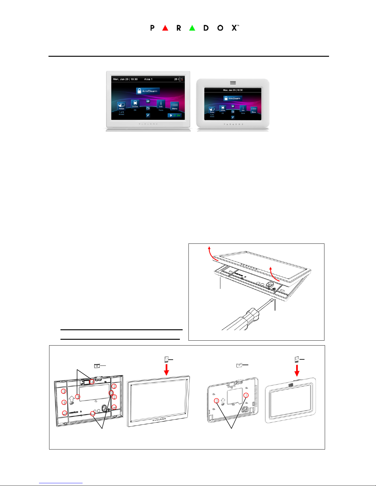
TM70 (7”) / TM50 (5”) Touchscreen Keypads
Installation Manual
Installation
WIRING: For the TM70 it is
recommended
to use 18 gauge wire unless wire feed
one keypad and distance is less than 100ft./30m.
TM50 we recommend 18 gauge as well, however, 22 gauge can be used up to 150ft.
Feeding wire (bus) should not have more than 1.0V drop, each TM70 represents 0.3 A max cur re n t, and TM50 150mA, wire resistance c a l c u lator can b e
found on the web. Resistance per:100ft 22 gauge wire = 1.6 Ohm, 18 gauge
0.64 Ohm. Voltage drop formula:
V = 2R x 0.3N (TM70), V = 2R x 0.15N (TM50)
R = Wire resistance, N= Number of TM70s fed by the wire, use lower gauge
wire if necessary.
Tab
Location
Tab
Location
1. Separate the top assembly from the
back plate. Insert a flathead screwdriver into the tab located, as shown
in Figure 1.
2. Mount the back plate to the wall or to
a gang box using appropriate screws.
Ensure that the UP arrow on the back
plate is in the up position.
Note: We recommend to feed
the TM70 with 18 gauge wire.
TM70 TM50
Figure 1
SD
Card
SD Card Cover
when needed
TM70
Gang Box
Gang Box
SD
Card
SD Card Cover
when needed
TM50
Gang Box
Figure 2
Page 2
3. Make sure the SD card is installed properly and locked with text facing backward to wall/connections facing to the front, as shown in Figure 2.
4. Secure the wire plug to the PCB socket the wires as per the color code to
match the Paradox keypad bus code. The blue wire is keypad zone input.
5. Attach the SD card cover if needed, then attach top to back top hooks first
then lock the bottom as per Figure 1. The SD card can be removed if necessary with a flat screw from the top if the metal cover is not attached or by
opening the keypad for loading pictures.
6. Power up the bus and verify that the voltage is higher than 11.5V (displayed
at the bottom right of the main screen as well as the boot sequence screen).
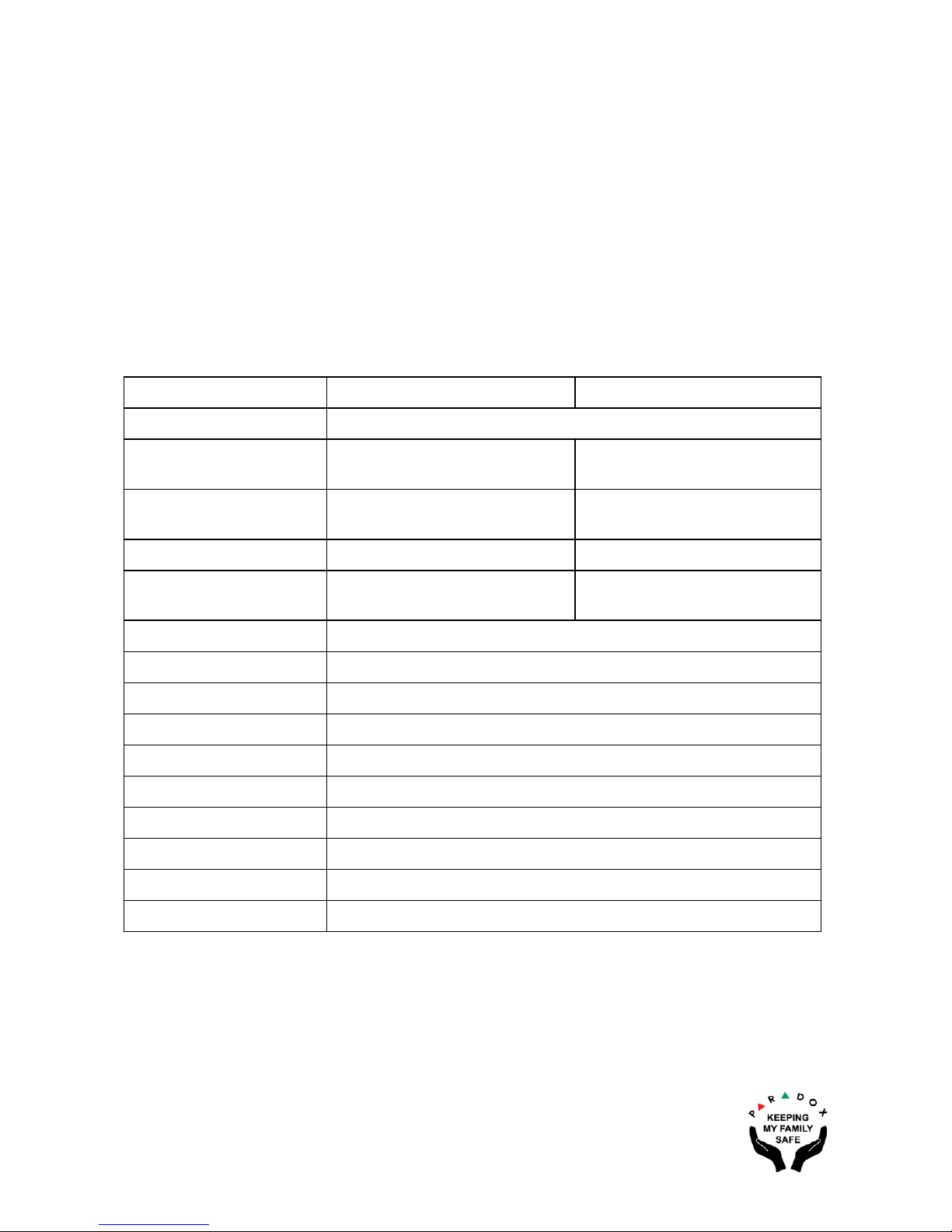
Technical Specifications
TM70 TM50
Power Input 9 to 15 VDC
Consumption
250mA at max brightness
+ 80mA sounder
150mA at max brightness
+ 80mA sounder
Wire Connection
18 Gauge 18 Gauge recommended,
22 Gauge
Display 7” 800 x 480 5” 480 x 272
Dimensions
17.7 x 11.4 x 1.5 cm
(7 x 4.5 x 0.6 in.)
14.2 x 9.5 x 1.4 cm
(5.6 x 3.75 x 0.56 in.)
Humidity 5-90%
Indoor Temp. Yes
SD Card 4GB; 2GB free
Input Zone
Tamper Built-in, Cover and Wall
Compatibility Swan, EVO, Spectra
Remote Upgrade Swan only
Jpeg Download Swan via Bus, EVO/Spectra SD Card
Auto Dim Yes
Chime Yes
Warranty: For complete warranty information on this product, please refer to
www.paradox.com/terms. Specifications may change without prior notice.
 Loading...