

Page 1

R
EFERENCE
1759EX V1.0
& I
NSTALLATION
M
ANUAL
1759EX
Page 2

Page 3
TABLE OF CONTENTS
INTRODUCTION ................................................. 3
Features.............................................................................................. 3
Specifications...................................................................................... 3
Detectors, Keypads and Expansion Modules ..................................... 4
INSTALLATION .................................................. 6
Location and Mounting ....................................................................... 6
Earth Ground ...................................................................................... 6
AC Power............................................................................................ 6
Backup Battery . .... .... .... .... .................................................................. 6
Auxiliary Power Terminals .................................................................. 8
Telephone Line Connection................................................................ 8
Bell Output Connection....................................................................... 8
Programmable Output Connections ................................................... 8
Single Zone Inputs .............................................................................. 9
Keypad and Keypad Zone Connections ............................................. 9
Keyswitch Connections..................................................................... 10
Fire Circuits....................................................................................... 10
PROGRAMMING METHODS.............................. 11
WinLoad Software for Windows........................................................ 11
Programming Using a Keypad.......................................................... 11
Config uri ng The LED Key p ad s .... ..................................................... 12
Programming Using A Paradox Memory Key ................................... 13
ACCESS CODES ............................................ 14
Access Code Length......................................................................... 14
Installer Code (Default: 000000)....................................................... 14
System Mas ter Cod e (Defa u lt: 12 34 56) ... ... .... .... .............................. 14
User Code Options ........................................................................... 14
Lock Master Code............................................................................. 15
Duress Code..................................................................................... 15
Bell Squawk On Arm/Disarm With Keypad ...................................... 29
Bell Squawk On Arm/disarm with Remote Control........................... 29
No Exit Delay When Arming with Remote Control ........................... 29
No Exit Delay Beeps and No Bell Squawk When Stay Arming........ 29
ALARM OPTIONS .......................................... 29
Bell Cut-Off Timer............................................................................. 29
Recycle Alarm.................................................................................. 29
Tamper Recog nitio n ........... .... .... ....................... .... .... ... .... ................ 30
Keypad Panic Options...................................................................... 30
Panic Lockout Timer......................................................................... 31
REPORTING AND DIALER SETTINGS .............. 32
Reporting/Dialer (Enable/Disable).................................................... 33
Report Codes................................................................................... 33
Central Station Telephone Numbers................................................ 35
Partition Acc ount N umb ers . .... .......................................................... 35
Reporting Formats............................................................................ 35
Pager Delay.. ... .... ............................................................................. 36
Event Call Dire ctio n. ....................... .... .... ... .... .................................. . 37
Dialing Meth od .................................................. .... .... ... .... ................ 37
Pulse Ratio ....................................................................................... 37
Bell on Communication Failure ........................................................ 37
Dial Tone Delay................................................................................ 37
Maximum Dialing Attempts............................................................... 37
Delay Between Dialing Attempts ...................................................... 38
Alternate Dial Option ........................................................................ 38
Recent Close Delay.......................................................................... 38
Auto Test Report .............................................................................. 38
Power Failure Report Delay ............................................................. 38
Disarm Reporting Options................................................................ 38
Zone Restore Rep ort Opt ions ................ ... .... .... ............................... 38
Telephone Line Monitoring (TLM).................................................... 38
ZONE PROGRAMMING ..................................... 16
What is an Expansion Input?............................................................ 16
Reassign Keypad Zone 2 ................................................................. 16
Reassign Zones to Expansion Inputs ............................................... 17
Zone Programming ........................................................................... 17
Zone Definitions................................................................................ 18
Exclusive Zone Definitions................................................................ 19
Zone Partition Assignment................................................................ 20
Zone Options .................................................................................... 20
Zone Speed ...................................................................................... 22
EOL Zones........................................................................................ 22
WIRELESS ZONE PROGRAMMING ................ 22
Wireless Transmitter Programming .................................................. 22
Viewing the Wireless Transmitter Signal Strength............................ 23
Serial Number Display...................................................................... 23
Supervis io n Opti on s...... .... ... .... ............ .... ... .... .... .............................. 24
Remote Control Programming .......................................................... 24
ARMING AND DISARMING OPTIONS ............... 27
Switch To Stay Arm in g ............ ......................................................... 27
Stay Arming with Delay..................................................................... 27
Regular Arming switches to Force Arming........................................ 27
Restrict Arming On Battery Fail ........................................................ 27
Restrict Arming On Tamper Failure .................................................. 27
Timed Auto-Arming........................................................................... 27
No Movement Auto-Arming .............................................................. 28
Auto-Arm in g Opti on s ............... ......................................................... 28
One-Touch Arming ........................................................................... 28
Exit Delay.......................................................................................... 28
PROGRAMMABLE OUTPUTS ........................ 39
PGM Activatio n Event ............ .... .... .................................................. 39
PGM Deactivat ion Event . ... .... .... ....................... .... .... ... .... ................ 40
PGM Delay........................................................ .... .... ... .... ................ 40
PGM Normal Stat e .......... ... ............ .... .... ... .... ................................... 40
PGM2 Strobe Option s . .... ... .... .... ...................................................... 40
Alarm Relay Options ........................................................................ 40
SYSTEM SETTINGS .................... ........ ....... ...... 41
Hardware Reset ............................................................................... 41
Installer Lock .................................................................................... 41
Keypad Lockout Fe atu re . ... .... .... ...................................................... 41
Battery Charge Current.................................................................... 41
Partitionin g ................................. .... .... .... ... ....................................... 41
System Real-Time Clock.................................................................. 41
Clock Adjust ..................................................................................... 41
Keypad Tamper Supervision............................................................ 42
Keypad Audible Trouble Warning..................................................... 42
Confidenti al Mod e .................. .... .............................................. .... ... . 42
Installer Quick Functions Keys ......................................................... 43
PGM Modules Supervi si on............................................................... 43
Printer Module Supervision .............................................................. 43
Zone Expansio n Bus Mo du le Supe rvi si on........................................ 43
Wireless Tran s mitte r Low Bat tery Sup erv isio n............................. ... . 44
Wireless Tran s mitte r Super vis io n Op ti ons .... .... .... .... ...................... . 44
ReProgram All Expansion Modules.................................................. 44
SETTINGS FOR WINLOAD SOFTWARE............ 45
Panel Answer Options...................................................................... 45
Panel Identifier ................................................................................. 45
S
PECTRA SERIES
1
Page 4
PC Password.................................................................................... 45
PC Telephone Number ..................................................................... 45
Call WinLoad Software ..................................................................... 45
Answer WinLoad Software ............................................................... 45
Auto Event Buffer Transmission....................................................... 46
Call Back WinLoa d .............. .... .... ..................................................... 46
USER OPERATION.......................................... 47
Trouble Display................................................................................. 47
Programmi ng Acces s Codes ............................................................ 48
Disarming & Deactivating an Alarm.................................................. 48
Regular Armin g........................ .... .... .... ... .......................................... 48
Stay Arming ...... .... ............................................................................ 49
Instant Arming................................................................................... 49
Force Arming .................................................................................... 49
Manual Bypass Programming........................................................... 49
One-Touch Arm in g .............. .... .... .... .... .................................. .... .... ... 50
Keyswitch Arming ............................................................................. 50
Panic Alarms..................................................................................... 50
Auto-Arming.............. .... ... .... ............................................................. 51
Alarm Memor y Displ ay..... .... .... .... .................................. .... .... .... .... ... 51
Programming Chime Zones.............................................................. 51
Keypad Muting.................................................................................. 51
Keypad Backlight (1686H and 1686V only)...................................... 51
FCC WARNINGS .............................................. 52
INDEX .............................................................. 54
LIST OF TABLES
Transformer Requirements Table....................................................... 6
Current Consumption Table................................................................ 8
Decimal and Hexadecimal Programming Table ............................... 11
Zone Recognition Table.................................................................... 16
Zone Display with 10-Zone LED Keypad.......................................... 17
Sections and Expansion Inputs ........................................................ 22
Button Options.................................................................................. 26
Remote Control Button Programming............................................... 26
Special Keys for Te le ph on e Numbe r s . ... .... ............ ... .... .... .... ........... 35
Reporting Formats ............................................................................ 36
Zone Tamper Report Code for Keypad Tamper Supervision Failure 42
Trouble List....................................................................................... 47
2
REFERENCE & INSTALLATION MANUAL
Page 5

1.1 FEATURES
• Up to 15 fully programmable zones
• Two completely independent partitions. Many of the features and options in the Spectra System can be independently set for each
partition such as event reporting, entry/exit delay, auto-arming and many more. All zones, the keyswitches and all user codes are
assigned to specif ic pa rtiti ons, which makes thi s a true par ti tioned syst em.
• Communication bus facilitates the adding, programming and monitoring of all expansion modul es.
• 1 Installer Code and 48 User Codes (including: 1 System Master, 2 Masters, and 1 Duress)
• 2 on-board, fully pr ogrammable outp uts (PGMs) and one 5A alarm relay
• Simple, direct and logical programming
• Event Call Direction: The Spectra 1759EX control panel events are divided into 5 groups of events. Each of these event groups can
be programmed wi th a sepa rate dialing sequence.
• Two 32-digit Central Station Telephone Numbers and one 32-digit Backup Telephone Number
• Contact ID, Pager Format and many more High-Speed Communication Form ats
• "False Alarm Preventi on" featu res such as: Int ell izone, Aut o Zone Shut down, Beep on Exit Delay, Programmable Delay Before Alarm
Transmission, and Recent Closing Report
• Regular Arming, Stay Arming, Instant Arming, For ce Arming, One-Touch Arming, Auto-Armin g, or Keyswi tch Arming
• 256 Event Buffer wit h time stamp
• Telephone Line Supervision
• Keypad activated panic alarms
• Compatible wit h Winloa d Security Syst em Management Soft ware for Windows®
1.2 SPECIFICATIONS
PART 1: INTRODUCTION
1.2.1 SPECTRA 1759EX CONTROL PANEL
• AC Power: 16Vac transformer wit h mini m um 20VA rating (Rec.: 40VA), 50 to 60Hz
• Battery: 12Vdc, 4Ah/7Ah
•Aux. Power:
• Bell Output:
• PGM Outputs: PGM1 = 150mA low-current output, PGM2 = 2.5A high-current output
• Alarm Relay: One form “C” relay rated @ 125V, 5A receptive load
++
+
600mA typical, 700mA maximum, fuseless shutdown @ 1.1A
1A, fuseless shutdown @ 3A
1.2.2 SPECTRA KEYPADS (1686H, 1686V, 1689 AND 1641 )
• Power input: Ty pically 9-16Vdc
• 1 standard keypad zone
• On-board tamper switch (optional)
1686H and 1686V 10-Zone LED Keypad
• Current consumption: 62 to 116mA
1689 16-Zone LED Keypad
• Current consumption: 50 to 117mA
1641 32-Character LCD Keypad
• Current consumption: 60 to 80mA
• PGM: 1 with 50mA current limit
• LCD: Super Twisted Nematic display (STN), Wide viewing angle, Backlight & Contrast
adjustable
Specifications may change without prior noti ce
+
Cannot exceed 200mA for UL installations
++
Cannot exceed 1A for UL instal lat ions
S
PECTRA
1759EX
3
Page 6
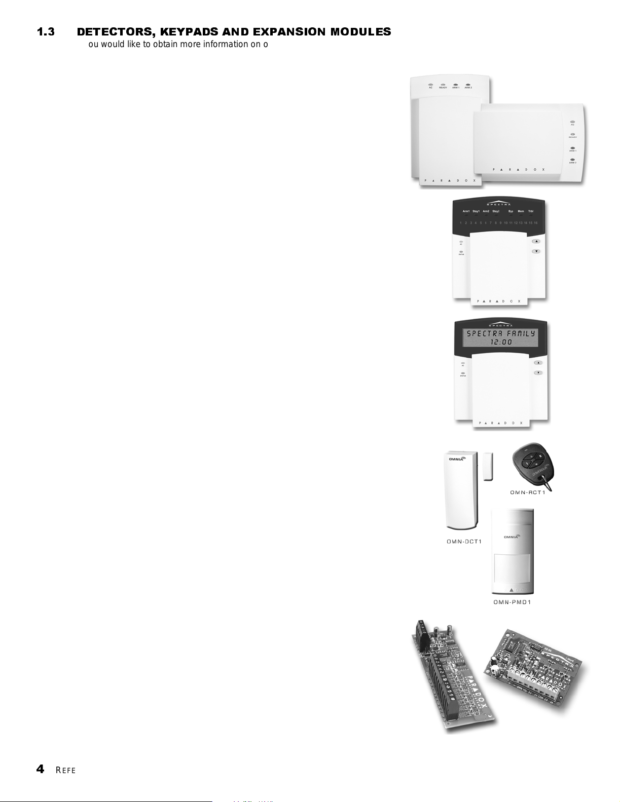
1.3 DETECTORS, KEYPADS AND EXPANSION MODULES
If you would like to obtain more inf ormati on on our line of keypad s, securit y system accesso ries or ot her securi ty produc ts, please
contact your local Paradox distri butor or visit our web sit e at htt p://www .paradox.ca.
1.3.1 SPECTRA 1686H AND 1686V 10-ZONE LED KEYPADS
The elegant Spectra 1686H/1686V LED keypads’ patented “Key
Light” feature provides a user-friendly display of the system’s current
status. For example, if zone 5 is open, the [5] key turns on. What
could be simpler? Designed to be compatible with any Spectra Series
control panel, our Euro-style Spectra keypads eliminate stocking and
ordering concer ns.
1.3.2 SPECTRA 1689 16-ZONE LED KEYPADS
The Spectra 1689 LED keypad’s brilliant display provides instant
feedback of the system’s current status. Designed to be compatible
with any Spectra Series control panel, this ergonomic and userfriendly keyp ad will complete any ins tallation.
1.3.3 SPECTRA 1641 LCD KEYPAD
The 1641 is a 32-character programmable LCD keypad which
includes a zone input as well as a PGM output. View zone, event and
trouble status for one or more partitions, display entry/exit delay,
adjust contras t, backli ght , and many other featur es. Most messag es in
the LCD keypad are programmable.
1.3.4 OMNIA 433MHZ WIRELESS TRANSMITTERS
With their encrypted wireless communication protocol and codehopping technology, the Omnia series transmitters offer reliability and
security. Operating at 433MHz, the series includes the Motion
Detector (OMN-PMD1), Door Contact (OMN-DCT1) and Remote
Control (OMN-RCT1).
1.3.5 ZONE EXPANSION BUS MODULES (NOT UL LISTED)
Connected to the Spectra control panel’ s communication bus, the fully
supervised zone expansion modules provide you with up to four
(SPC-ZX4 and APR3-ZX4) or up to eight (SPC-ZX8 and APR3-ZX8)
additional hardwi red inputs and one normally open 50mA PGM output
(SPC-ZX8 and APR3-ZX8 only). Due to its Auto-Panel Recognition
feature, modules with the APR3- prefix are compatible with Spectra,
Digiplex and DigiplexNE.
4
REFERENCE & INSTALLATION MANUAL
Page 7
1.3.6 PRINTER MODULE
The Printer Module (APR3-PRT1) provides you with the ability to
automatically print events as they occur in the system or the events
can be stored in th e mod ule’s event buffer so you can print t he events
manually. The events can be sent to a dot matrix printer or can be
viewed and printed from a computer. Includes a 50mA PGM output.
Due to its Auto-Panel Recognition feature, modules with the APR3prefix are comp ati ble with Spectra, Digip lex and Digi plexNE.
1.3.7 4-PGM OUTPUT MODULE (NOT UL LISTED)
When connected to the Spectra communication bus, this module
(APR3-PGM4) will provide four additional 5A programmable outputs
to the Spectra system. Due to its Auto-Panel Recognition feature,
modules with the APR3- prefix are compatible with Spectra, Digiplex
and DigiplexNE.
1.3.8 INTOUCH™
Using a touch-tone telephone, users can arm or disarm their security
system from a distance as well as activate or deactivate the APR3ADM2’s on-board PGM output. Due to its Auto-Panel Recognition
feature, modules with the APR3- prefix are compatible with Spectra,
Digiplex and DigiplexNE.
V
OICE-ASSISTED ARM/DISARM MODULE
1.3.9 PARAVOXTM - VOICE DIALER (NOT UL LISTED)
In areas where security system monitoring is not available, let the
sophisticated Paravox voice dialer take over. Compatible with any
control panel, the Par avox will verbal ly report system status by phone,
advising of detection of burglary, fire, flood or any other situation
programmed to generate a report condition. Fully programmable over
the telephone (no external keypad required), the Paravox guides the
end user through all system functions with a full set of voice prompts.
All the user needs to remember is their P.I.N. The “Key Ahead” feature
eliminates the frustration and time wasted for experienced operators
by allowing them to key-in selections before a prompt ends.
1.3.10 DIGITAL DETECTORS
The Paradox DigigardTM (50/60/70) digital motion detectors can
immediately identify the signal produced by a moving human body
and will not be triggered by any other occurrences in the protected
area. False alarms are virtually eliminated. Using 100% digital
detection technology and smart digital processing software leaves no
room for error. With the Digigard 70, animal lovers can maximize their
security protection. Thanks to th e unique design of the patent-pending
Digigard “pet-friendly” lens and dual “decision” optics, the Digigard 70
double-checks every movement signal.
(NOT UL
LISTED
)
Take all that’s good about infrared digital detection, add an advanced
microwave “supervisor” and you have Digital Vision 525D and 526D
motion detectors. Once the Vision’s digital infrared detector identifies
an intruder, its microwave sensor must confirm the presence of
movement before an alarm is triggered.
S
PECTRA
1759EX
5
Page 8

PART 2: INSTALLATION
2.1 LOCATION AND MOUNTING
Before mounting the cabinet, push the fi ve white nylon m ounting studs into the back of the cabinet. Pull all cables into the cabinet
and prepare them for connection before mounting the circuit board into the back of the cabinet. Select a centralized installation
site on the main floor that isn't easily accessible to intruders and leave at least 2in. (5cm) around the panel box to permit
adequate ventilation and heat dissipation. The installation site should be dry and close to an AC source, ground connection and
telephone line connection. Avoid ins tallation near or in the path of st rong RF fields (i.e. neon lights, computers), on or near metal
objects, circuit breaker boxes, air conditioners and heater ducts since they may cause interference and reduce sensitivity. Avoid
installing the 1759EX in the basement.
2.2 EARTH GROUND
Connect the zone and dialer ground terminals from the control panel to the metallic enclosure and cold water pipe or grounding
rod as per local electrical codes.
2.3 AC POWER
Do not use any switch-controlled outlets to power the transformer. Connect the transformer as shown in Figure 2.1 on page 6.
Use Table 1 to determine the required transformer.
For maximum lightning protection, use separate earth grounds for the zone and dialer grounds as shown in
Figure 2.2 on page 7. For UL installati ons, the metallic enclosure must be grounded to the cold water pipe.
T able 1:
T ransformer Requirements Table
Transformer: Amseco XP-1620 16VAC 20VA
(not verified by UL)
Spectra DC Power Supply rated at: 1.2A 1.5A
Auxiliary Supply can provide a maximum of: typ: 600mA, max: 700mA typ: 600mA, max: 700mA
Acceptable Battery Charge Currents 350mA 350mA/700mA
UL: Basler Electric BE156240CAA007
16.5VAC 40VA
Do not exceed 200mA for UL instal lat ions
2.4 BACKUP BATTERY
To provide power durin g a power loss, connect a 12Vdc 4Ah rechar geable acid/lead or gel cell backup batte ry as shown in Figure
2.1 on page 6. Use a 7Ah battery to comply with UL fire requirements. Connect the backup battery after applying AC power.
When installing verify proper polarity as reversed connections will blow the battery fuse. Also, refer to Battery Charge Current on
page 41.
2.4.1 BATTERY TEST
If the battery is disconnected or if the battery fuse is blown, a No/Low Battery failure will appear in the keypads’ Trouble Display
(see page47). This trouble will also appear if the battery’s capacity is too low or if the voltage drops to 10.5 volts or lower while
the control p anel is running on the backup battery. At 8.5 volts or lo wer, the panel shuts down and all outputs close.
Figure 2.1: AC Power and Backup Battery Connections
6
REFERENCE & INSTALLATION MANUAL
Page 9
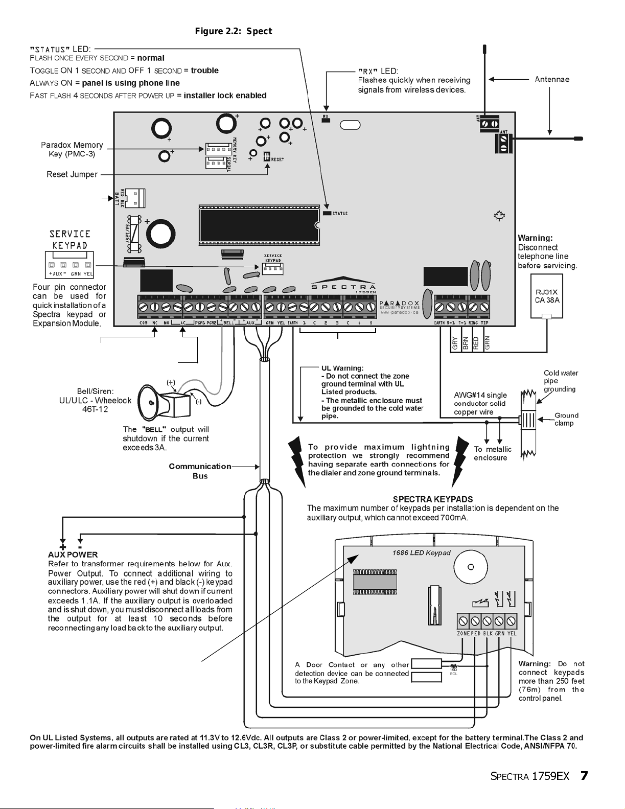
Refer to Single Zone Inputs on
Refer to AC Power
.
and Backup Battery
Connections on
page 6.
Figure 2.2: Spectra 1759EX Control Panel Overview
To connect the 5A Alarm Relay and the PGMs,
refer to Relay and PGM Connections on page 9
To connect AC power, refer to AC Power and
Backup Battery Connections on page 6.
page 9
For the keypad’ s zone, EOL and tamper
configurations, refer to Configuring The
LED Keypads on page 12.
S
PECTRA
1759EX
7
Page 10
2.5 AUXILIARY POWER TERMINALS
The auxiliary power supply terminals can be used to power motion detectors, keypads and other modules or accessories in the
security sy stem. A fuseless circuit protec ts the power supply against current overload and auto ma ti cally shuts down if the current
exceeds 1.1A. If this occurs, the Maximum Auxiliary Current failure will appear in the keypads’ Trouble Display (see page 47).
Therefore, the combined current consumption of devices connected to the auxiliary power supply should not exceed 700mA. If
the auxiliary output is overloaded and is shut down, you must disconnect all loads from the output for at least 10 seconds before
reconne c ting any load ba c k to th e au x ilia r y o u tp u t.
Modules with the APR- prefix are compatible with the Spectra 1759EX and Digiplex. Modules with the APR3- prefix are
compatible with the Spectr a 1759EX, Digiplex and Digipl exNE.
Table 2:
Modules Current Consumption
Spectra 1686H and 1686V 10-Zone LED Keypad 62mA 116mA
Spectra 1689 16-Zone LED Keypad 50mA 1 17mA
Spectra 1641 LCD Keypad 60mA 80mA
4-Zone Hardwire Modules (APR3-ZX4/SPC-ZX4) 12mA 12mA
8-Zone Hardwire Modules (APR3-ZX8/SPC-ZX8) 30mA 30mA
4-PGM Output Module (APR3-PGM4) 13mA 150mA
Printer Module (APR3-PRT1) 22mA 40mA
InTouch Voice-Assisted Arm/Disarm Module (APR3- ADM2) 70mA 105mA
Motion Detector s (see detector instr uctions for details) 10 to 50mA
2.6 TELEPHONE LINE CONNECTION
In order to report system events to the centr al station, you must connect the incoming telephone company wires into the TIP and
RING connections of the control panel and then run the wires from T1 and R1 to the telephone or telephone system as shown in
Figure 2.2 on page 7.
2.7 BELL OUTPUT CONNECTION
The BELL+ and BELL- terminal s power bells, sirens and ot her warnin g devices re quiring a stea dy volt age out put during an al arm.
The bell output supplies 12VDC upon alarm and can support one 30-watt or two 20-watt sirens. The bell output uses a fuseless
circuit and will automatically shut down if the current exceeds 3A. When this occurs the Maximum Bell Current failure will only
appear in the keypads’ Trouble Display (see page 47) during an alarm. If the load on the BELL terminals returns to normal, the
control panel will re-instate power to the BELL terminals during the next alarm. When connecting sirens, please verify correct
polarity. Connect the positive lead to the BELL+ terminal and the negative lead to the BELL- terminal of the control panel as
shown in Figure 2.2 on page 7.
If the BELL output is not being used, the Bell Disconnected failure will remain in the keypads’ Trouble Display
(see page 47). To avoid this connect a 1KΩ resistor across the BELL terminals.
Current Consumption Table
Typical Maximum
2.8 PROGRAMMABLE OUTPUT CONNECTIONS
When a specific event occurs in the system, a PGM can reset smoke detectors, activate strobe lights, open/close garage doors
and much more.
2.8.1 ALARM RELAY AND PGMS
The Spectra 1759EX control panel includes two on-board programmable outputs (PGMs). For details on how to program the
PGM, refer to PGM Programming on page39. PGM1 can support up to 150mA while PGM2 supports up to 2.5A (see Figure 2.3
on page 9) and can be used as a strobe output (see page 40). The PGMs are limi ted by the power source being used. If powered
by:
•
The
AUX
terminals.
nected to the
nected to the
consumption wil l not 100mA.
•
An external power su pply .
PGM2. If the external power supply’s current consumption limit is less than that of the PGM it is connected to, than the current consumption will not exceed the power supply’s current limit.
The Spectra 1759EX contr ol panel a lso has a 5A relay. This relay can be connecte d as shown in Figure 2.3 on page 9. The Alarm
Relay can be programmed to follow the bell output or the activation and deactivation of the Global PGM (see Alarm Relay
Options on page40).
8
REFERENCE & INSTALLATION MANUAL
The current consumption of the
AUX
terminals (i.e. modules and PGMs) cannot exceed 700mA combined. For example, if there are six modules con-
AUX
terminals that are using 600mA and you wish to power the PGM using the
If usi ng an external power suppl y, the current consumpt ion canno t ex ceed 1 50mA for PGM1 and 2.5A for
AUX
terminals cannot exceed 700mA. Therefore, whatever devices are con-
AUX
terminals, the PGM’s current
Page 11
2.9 SINGLE ZONE INPUTS
AUX+ or External Power Supply.
Detection devices such as motion detectors and door contacts are connected to the control panel's zone input terminals. Figure
2.4 (below) demonstrates single zone input terminal connections recognized by Spectra. Once connected, the associated zone's
parameters must be def ined. For details refer to Zone Programming on page 16.
Figure 2.3: Relay and PGM Connections
See Pr ogrammable Output
Connections on page 8
Figure 2.4: Single Zone Input Connecti ons
2.10 KEYPAD AND KEYPAD ZONE CONNECTIONS
To connect the keypads to the control panel, remove the back cover and wire the GRN, YEL, RED, and BLK terminals of each
keypad to the corresponding terminals on the control panel as shown in Figure 2.2 on page 7. There is no limit to the number of
keypads that can be connected to the control panel so long as the current consumption does not surpass 700mA. For details on
Keypad Tamper Supervision see section 11.8 on page 42.
S
PECTRA
1759EX
9
Page 12
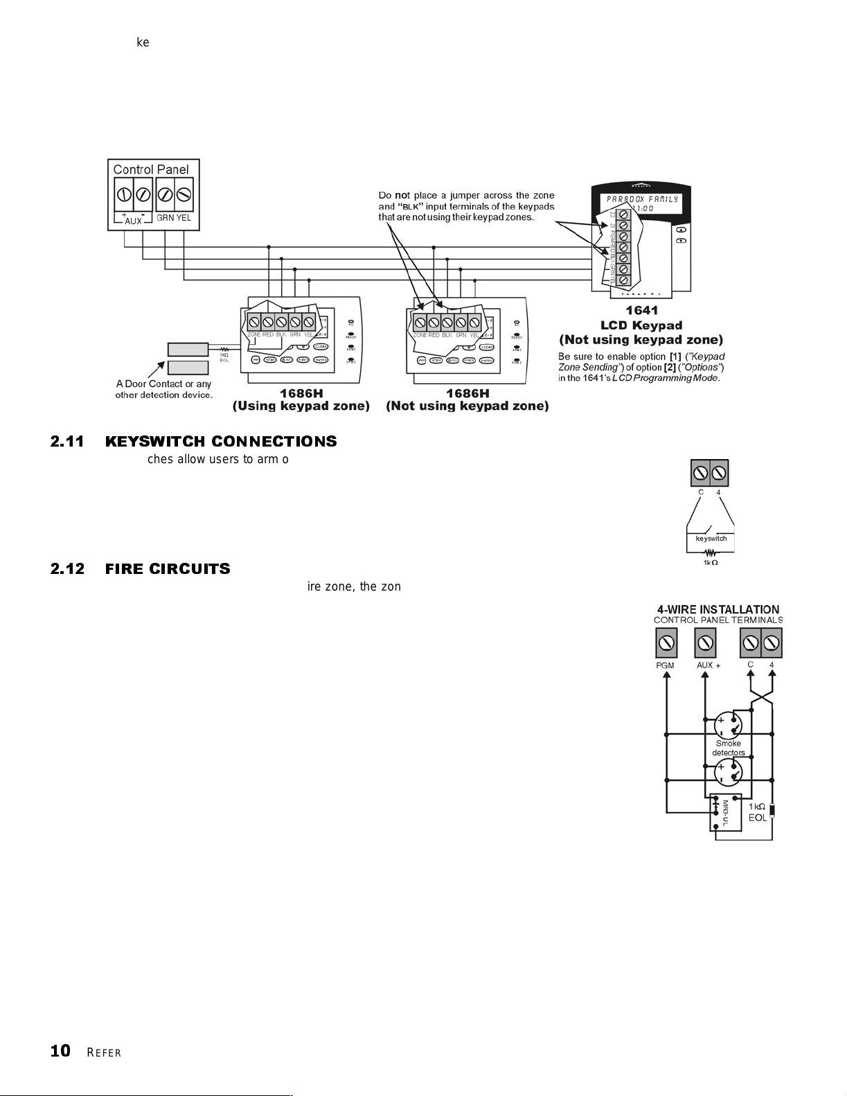
Each keypad has one zone input terminal, allowing you to connect one motion detector or door contact directly to a keypad. The
Figure 2.6: Keyswitch
Figure 2.7: Fire Zones
keypad can then communicate the status of the zone to the control panel. A maximum of two keypad zones can be used with
each control panel. After connecting the device, the zone's parameters must be defined. For details on zone recognition and
Zone Programming refer to page 16. Also, refer to the feature Reassign Keypad Zone 2 on page16.
Example: A door contact located at the entry point of an establishment can be wired directly to the input terminal of the entry
point keypad i nstead of wiring the door co ntact all the way to the contr ol panel.
Figure 2.5: Keypad Zone Connections
2.11 KEYSWITCH CONNECTIONS
Keyswitches allow users to arm or disarm a partition by pushing a button or by activating a
switch with a key. Connect the keyswitch as shown in Figure 2.6 directly to the control
panel terminals. Once a keyswitch is connected, it must be assigned to a zone and its
parameters must be programmed (see Zone Programming on page 16 and Keyswitch
Options on page21).
2.12 FIRE CIRCUITS
When a zone is programmed as a Fire zone, the zone becomes normally open and requires
an EOL resistor. If a line short occurs or if the smoke detector becomes active, whether the
system is armed or disarmed, the control panel will generate an alarm. If a trouble occurs on a
Fire zone, the Fire Loop T rouble will appear in the keypads ’ Tr oub le Display (s ee pag e 47) and
the control p anel can transmit the Fire Loop Trouble report, if programmed, in section [206] .
2.12.1 4-WIRE INSTALLATION:
Any on-board zone can be defined as a Fire Zone (see page 18) when using the 4wire insta ll ation. Connect the smoke detecto rs as shown in Figu re 2. 7 directly to t he
control panel terminals. Program the PGM with the “[
Activation Event (see pa ge 39) so the smoke detectors can be reset by pressing the
[
PG] or [FNC1] key. Pressing the [PG] or [FNC1] key will interrupt power to the smoke
detectors for 4 seconds (see PGM Delay on page 40).
PG]/[FNC1] Key was Pressed”
10
REFERENCE & INSTALLATION MANUAL
Page 13

PART 3: PROGRAMMING METHODS
3.1 WINLOAD SOFTWARE FOR WINDOWS
Program the Spectra Series control panels remotely or on-site using the Winload Software for Windows®. For more information,
contact your local Paradox Distributor or visit our web site at http://www.paradox.ca. If you are using the WinLoad software, you
must program the features explained on pages 45 and 46.
3.2 PROGRAMMING USING A KEYPAD
Use the supplied Spectra 1759EX Programming Guide to keep track of which sections were programmed and how. We
recommend you read this ent ire manual before you begin programming.
How Do I Enter Programming Mode?
STEP 1: Press [
STEP 2: Enter your [
STEP 3: Enter 3-digit [
STEP 4: Enter required [
3.2.1 SINGLE DIGIT DATA ENTRY METHOD (HEXADECIMAL AND DECIMAL)
Single Digit Data Entry is used in all sections except those specified in the Feature Select Programming Method. After
entering the programming mode as described in the shaded box above, some sections will require that you enter
Decimal values from 000 to 255. Other sections will require that you enter Hexadecimal values from 0 to F. Th e
required data will be clearly indicated in this manual as well as in the Spectra 1759EX Programming Guide. When
entering the final digit in a section, the control panel will automatically save and advance to the next section. Except
sections 001 to 016, after entering the fir st two digits the control panel will swit ch to Feature Select Programming.
ENTER]
INSTALLER CODE] (default: 000000)
SECTION] you wish to program
DATA]
T able 3:
Decimal and Hexadecimal Programming Table
Value or Action What Do I Press? What Do I See?
Values 1 to 9 [1] to [9]
A (hexa only) [0] [0 (10)] [10] 0
B (hexa only) [
C (hexa only) [
D (hexa only) [
E (hexa only) [
F (hexa only) [
Exit Without Saving [
Insert Blank Digit [
Save Data [
STAY][STAY][11] B
BYP][BYP] [12] C
MEM][MEM] [13] D
TBL] / [TRBL][TBL] [14] E
PG] / [FNC1] [PG] [15] F
CLEAR][ENTER] flashes [ARM1] & [STAY1] flash “SECTION [ ]”
FORCE] Di splays next digit or next section
ENTER] Advances to the next section
3.2.2 FEATURE SELECT PROGRAMM ING METHOD
After entering sections [001] to [016], [126] to [138], and [302] to [348], each option f rom [1] to [8] represents a specific
feature or option. Press the key corresponding to the desired option and the corresponding light will illuminate or the
option number will appear in the LCD display. This means the option is on. Press the key again to extinguish the
corresponding light or remove the digit from the LCD display, thereby, turning off the option. Press the [
set all 8 options to off. Press the keys until the current section’s options are set. When the options are set, press the
[
ENTER] key to save and advance to the next section.
3.2.3 DATA DISPLAY MODE (LED KEYPADS ONLY)
In the Data Display Mode you can view the programmed contents of each se ction one digit at a time. After entering the
desired 3-digit section (see step 3 of the shaded box on page 11), press the [
Mode (will not function with sections using Multiple Feature Select Programming).
10-Zone LED 16-Zone LED LCD
[1] to [9] [1] to [9] [1] to [9]
FORCE] key to
ENTER] key to access the Data Display
S
PECTRA
1759EX
11
Page 14
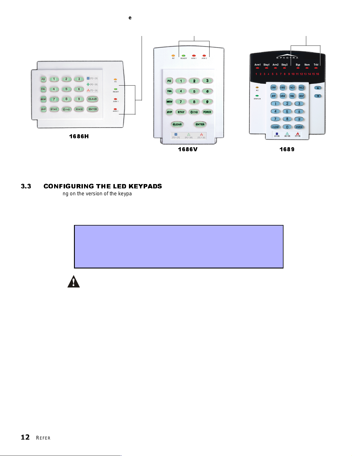
Figure 3.1: Data Displ ay M ode (LED Keypads Only)
[enter]
s
]
To access the Data Display Mode, pre ss th e
to flash indicating that you are in the Data Display Mode.
key after ent ering a section and be fore entering any data. The three LEDs as indica ted wil l begin
1686H
1686V 1689
Each time the [ENTER] key is pressed, the keypad will display the next digit in the current section and will continue through all the following section
one digit at a time without changing the programmed values. Not available for sections using the Multiple Feature Select Method. Press the [CLEAR
key at any time to exit the Data Di splay Mode.
3.3 CONFIGURING THE LED KEYPADS
Depending on the version of the keypad, two methods can be used to configure the LED keypads (1686H, 1686V and 1689):
3.3.1 CONFIGURING THE 1686H, 1686V AND 1689 KEYPADS V2.0 OR HIGHER
The keypad’s zone number, EOL definition and tamper switch are programmed through the control panel’s
programming mode. To do so:
How Do I Configure The Keypad?
STEP 1: Press [
STEP 2: Enter your [
STEP 3: Press the [
STEP 4: Press the desired key ([ 1] to [3]. See below)
STEP 5: Press [
PLEASE NOTE: After two minutes, the keypad exit s programming mode.
Key [1] - Keypad Zone Selection
Key [1] determines whether the keypad’s zone is Keypad Zone 1 or Keypad Zone 2. When key [1] is OFF (not
illuminated), the keypad’s zone is Keypad Zone 1. When key [1] is ON (illuminated), the keypad’s zone is Keypad Zone 2.
Key [1] OFF - Keyp ad Zone 1 (default)
Key [1] ON - Keypa d Zone 2
Key [2] - EOL Definition
Key [2] determines the keypad zone’s EOL definition. When key [2] is OFF (not illuminated), EOL is disabled and the
keypad zone will use the on-board EOL resistor. When key [2] is ON (illuminated), EOL is enabled and the keypad
zone requires t hat an external EOL resi stor be connected (refer to Spectra 1759 EX Co ntr ol Panel Overview on page 7
for more details).
Key [2] OFF - EOL disabled
Key [2] ON - EOL enabled (def ault)
ENTER]
INSTALLER CODE] (default: 000000)
PG] (1686H/V) / [FNC1] (1689) key and hold it for 3 seconds.
ENTER] to exit programming mode
Key [3] - On-Board Tamper
Key [3] enables or disables the keypad’s on-board tamper switch. When key [3] is OFF (not illuminated), the tamper
switch is disabled. When key [3] is ON (illuminated), the tamper switch is enabled.
Key [3] OFF - On-board tamper switch disabled
Key [3] ON - On-boar d tamper switch enabled
12
REFERENCE & INSTALLATION MANUAL
Page 15
PLEASE NOTE: The keypad can be ordered with or without a tamper switch. If the keypad has no
tamper switch, key [3] will be OFF by default. If the keypad has a tamper switch, key [3] will be ON by
default.
3.3.2 CONFIGURING THE 1686H, 1686V AND 1689 KEYPADS PRIOR TO V2.0
The keypad’s zone number and EOL definition are defined through the jumpers located on the PCB board. The
jumpers are as follows:
J1 - Keypad Zone Select Jumper
Jumper J1 determines whether the keypad’s zone is Keypad Zone 1 or Keypad Zone 2. When the jumper is OFF, the
keypad’s zone is Keypad Zone 2. When the jumper is ON, the keypad’s zone is Keypad Zone 1.
J1 OFF - Keypad Zone 2
J1 ON - Keypad Zone 1
J2 - EOL Definition Jumper
Jumper J2 determines the keypad zone’s EOL definition. When the jumper is OFF, EOL is disabled and the keypad zone
uses the on - bo ard EOL resi s t or. When the jump er is ON, EOL is enabled an d t he keypad zone r e qui re s t h at an externa l
EOL resistor be connected (refer to Spectra 1759EX Control Panel Overview on page 7 and more details).
J2 OFF - EOL disabled
J2 ON - EOL enabled
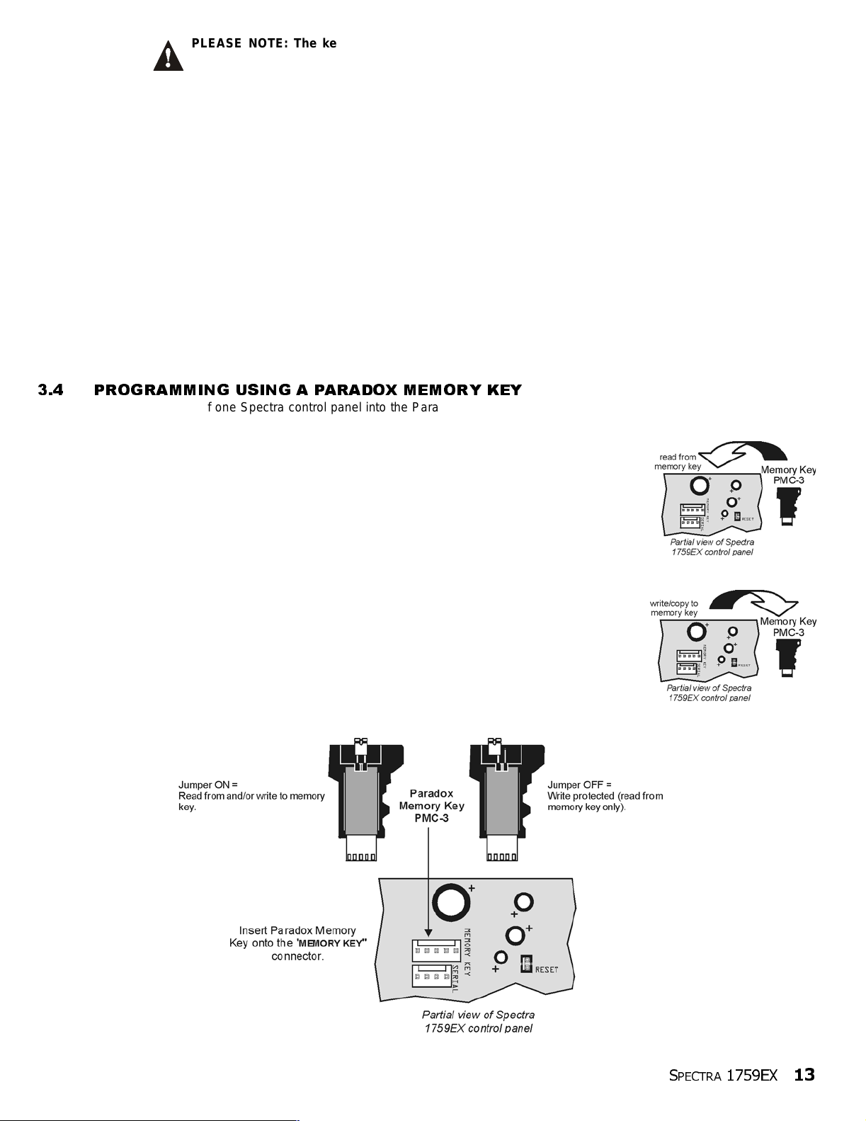
3.4 PROGRAMMING USING A PARADOX MEMORY KEY
Copy the sections of one Spectra control panel into the Paradox Memor y Key (PMC-3). Then copy the contents of the Memory
Key into as many Spectra control panels as neede d. Each panel is programmed in l ess than 3 seconds.
Download to DESTINATION Control Panel
1) Remove AC and battery power from the control panel.
2) Place the Memory Key on the serial con nect or lab eled KEY of the Spectra Contr ol Panel that is
to receive the contents of the Memory Key.
3) Reapply AC and battery power.
4) In installer programming mode, enter section [900], then press [
5) When the keypad emits a Confirmation Beep, remo ve the Memory Key.
6) Enter section [750] t o repr ogram the modules with the information downloaded from the
Paradox Memory Key.
Copy to Memory Key from SOURCE Control Panel
1) Remove AC and battery power from the control panel.
2) Place Memory Key on the serial connector labeled KEY of the Spectra Control Panel that you
want to copy. Make sure the write protect jumper of the Memory Key is on.
3) Reapply AC and battery power.
4) In installer programming mode, enter section [902], then press [
5) When the keypad em it s a Confirmation Beep, remove the Memory Key. Remove the Memory
Key’s jumper if you do not wish to accident ally overwrite it s contents.
Figure 3.2: Paradox Memory Key
ENTER] to acknowledge.
ENTER] to acknowledge.
S
PECTRA
1759EX
13
Page 16
PAR T 4: ACCESS CO DES
The Spectra 1759EX contr ol panel supports the following access codes:
INSTALLER CODE: Used to program all control panel settings except User Access Codes.
SYSTEM MASTER CODE (001) Provi des full access. Arm and disarm usin g any method desc ribed in the User Code Options
in section 4.4 as well as program the User Access Codes.
Master Code 1 (002): Permanently assigned to partition 1. Same as a regular User Code except it can also
program access codes for User Codes assigned to partition 1.
Master Code 2 (003): P ermanently assigned to partition 2. Same as a regul ar User Code except it can program
access c odes for User Codes assigned to par ti tion 2. If the system is not p artitioned Master
Code 002 will be assigned to partition 1.
45 User Codes (004 to 048): Can arm and disarm as per User Code Option s in sec tion 4.4.
4.1 ACCESS CODE LENGTH
Section [127]: System Options
Option
Option
All access codes can be set to lengths of either 4- or 6-digits. When the 4-digit option is selected, entering a 4-digit code will allow
access. Using th e 6-di git option, entering 6 digits is requir ed to al low access.
[2]
OFF = 6-Digit Access Codes
[2]
ON = 4-Digit Access Codes (default)
If the Access Code Length is changed from four digits to six digits when access codes have already been
programmed, the control panel will automatically add the last 2 digits by using the first 2 digits. For example, if
the access code is 1234 and you switch to 6 digits, the code will become 123412. Be sure to verify the access
codes after switching from 4-digit access codes to 6-digit codes. When switching from six digits to four digits,
the control panel will simply remove the final two digits of the access code. For example, 123456 will become
1234.
4.2 INSTALLER CODE (Default: 000000)
The Installer Code is used to enter the control panel's programming mode (see page 11), which allows you to program all the
features, options and commands of the control panel. The Installer Code can be 4- or 6-digits in length (see above) where each
digit can be any value from 0 to 9. The Installer Code cannot be used to pro gram Master Code 1, Ma ster Code 2 or User Access
Codes. To program the Install er Code press:
[
ENTER] + [CURRENT INSTALLER CODE] + [281] + new 4- or 6-digit Installer Code
4.3 SYSTEM MASTER CODE (Default: 123456)
The Installer Code can be used to program the System Master Code. With the System Master Code a user can use any arming
method and can program any User Access Code, but not the User Code Options. The System Master Code can be 4 or 6 digits
in length (see secti on 4.1), where each digit can be any digit from 0 to 9. To change the System Master Code press:
[
ENTER] + [INSTALLER CODE] + [301] + new 4- or 6-digit System Master Code
4.4 USER CODE OPTIONS
Sections
The User Code Options define which arming methods each user can use to arm or disarm the system. Regardless of these
settings, all users can Regular Arm assigned partitions and all users except those with the Arm Only option can disarm an
assigned partition, regardless of how it is armed. Select one or more of the options described on the following pages for each
User Access Code, where sections [302] to [ 348] represent User Access Codes 002 to 048. For information on how User Access
Codes are programmed, pl ease refer to page 48.
4.4.1 PARTITION 1 ASSIGNMENT
[302]
to
[348]
: Options
Sections [302] to [348]: User Codes 002 to 048
Option
Option
If Partitioned (see page 41), user codes with this option enabled can arm and disarm partition 1.
[1]
OFF = Deny access to partition 1
[1]
ON = User code has access to partition 1 (default)
[1]
to
[7]
14
REFERENCE & INSTALLATION MANUAL
If the system is not partitioned, you must assign partition 1 to the User Access Code. Otherwise, the
User Access Code will be considered disabled.
Page 17
4.4.2 PARTITION 2 ASSIGNMENT
Sections [302] to [348]: User Codes 002 to 048
Option
Option
If the system is partitioned (see page 41), user codes with this option enabled can arm and disarm partition 2. If the
system is not partitioned, the control panel ignores this option.
[2]
OFF = Deny access to partition 2 (default)
[2]
ON = User code has access to partition 2
4.4.3 BYPASS PROGRAMMING
Sections [302] to [348]: User Codes 002 to 048
Option
Option
User codes with this option enabled can perfo rm B ypass Programming in assigned partitions.
[3]
OFF = Bypass Programming Disabled
[3]
ON = Bypass Programming Enabled (default)
4.4.4 STAY ARMING
Sections [302] to [348]: User Codes 002 to 048
Option
Option
User codes with this option enabled can Stay Arm assigned partitions.
[4]
OFF = Stay Arming Disabled
[4]
ON = Stay Arming Enabled for selected User Code (default)
4.4.5 FORCE ARMING
Sections [302] to [348]: User Codes 002 to 048
Option
Option
User codes with this option enabled can For ce Arm assigned partitions.
[5]
OFF = Force Arming Disabled (default)
[5]
ON = Force Arming Enabled for selected User Code
4.4.6 ARM ONLY
Sections [302] to [348]: User Codes 002 to 048
Option
Option
The user code with this option enabled can arm assigned partitions, but cannot disarm any partitions. The type of
arming is dependent on the other User Code Options se lected. Please note that with the Arm Only option, the user can
cancel a recently armed system by re-entering the access code before the end of the Exit Delay.
[6]
OFF = Arm Only Disabled (default)
[6]
ON = Arm Only Enabled for selected User Code
4.4.7 PGM ACTIVATION
Sections [302] to [348]: User Codes 002 to 048
Option
Option
With option [7] off, entering the access code will arm or disarm according to the programmed User Code Options as
well as activate or deactivate a PGM. The appropriate PGM Activation/Deactivation Event must also be programmed
(see page39). With option [7] on, the control panel will ignore all other User Code Options. Therefore, entering the
access code will only activate or deactivate the PGM.
[7]
OFF = User Code follows
[7]
ON = User Code can activate a PGM only
4.5 LOCK MASTER CODE
Section [127]: System Options
Option
[4]
OFF = Lock System Master Code Disabled (default)
Option
With this feature enabled, the control panel will lock the System Master Code (001). This means that the System Master Code
cannot be deleted, but it can be changed.
[4]
ON = Lock System Master Code Enabled
4.6 DURESS CODE
Section [127] = System Options
Option
Option
With this feature enabled, User Code 048 becomes a Duress Code. When forced to arm or disarm their system, users can enter
a Duress Code (User Code 048) to arm or di sarm the system which can imm ediately transmit a silent alert to the Cent ral Station,
transmitting the duress report code pro gramm ed in section [196].
[6]
OFF = Duress Code Disabled (default)
[6]
ON = User Code 048 becomes a Duress code
User Code Options
and can activate a PGM (default)
S
PECTRA
1759EX
15
Page 18
PART 5: ZONE PROGRAMMING
The Spectra 1759EX contr ol panel’s zone assignment depends on wher e the det ection devices are connected (see Table 4).
T able 4:
Device connected to
which inpu t?
Control Panel
Input 1 = Zone 1
Input 2 = Zone 2
Input 3 = Zone 3
Input 4 = Zone 4
Input 5 = Zone 5
Keypad
Zone 1 = Zone 6
Zone 2 = Zone 7
Expansion
Input 1 = Zone 8
Input 2 = Zone 9
Input 3 = Zone 10
Input 4 = Zone 11
Input 5 = Zone 12
Input 6 = Zone 13
Input 7 = Zone 14
Input 8 = Zone 15
Zone Recognition Table
1759EX
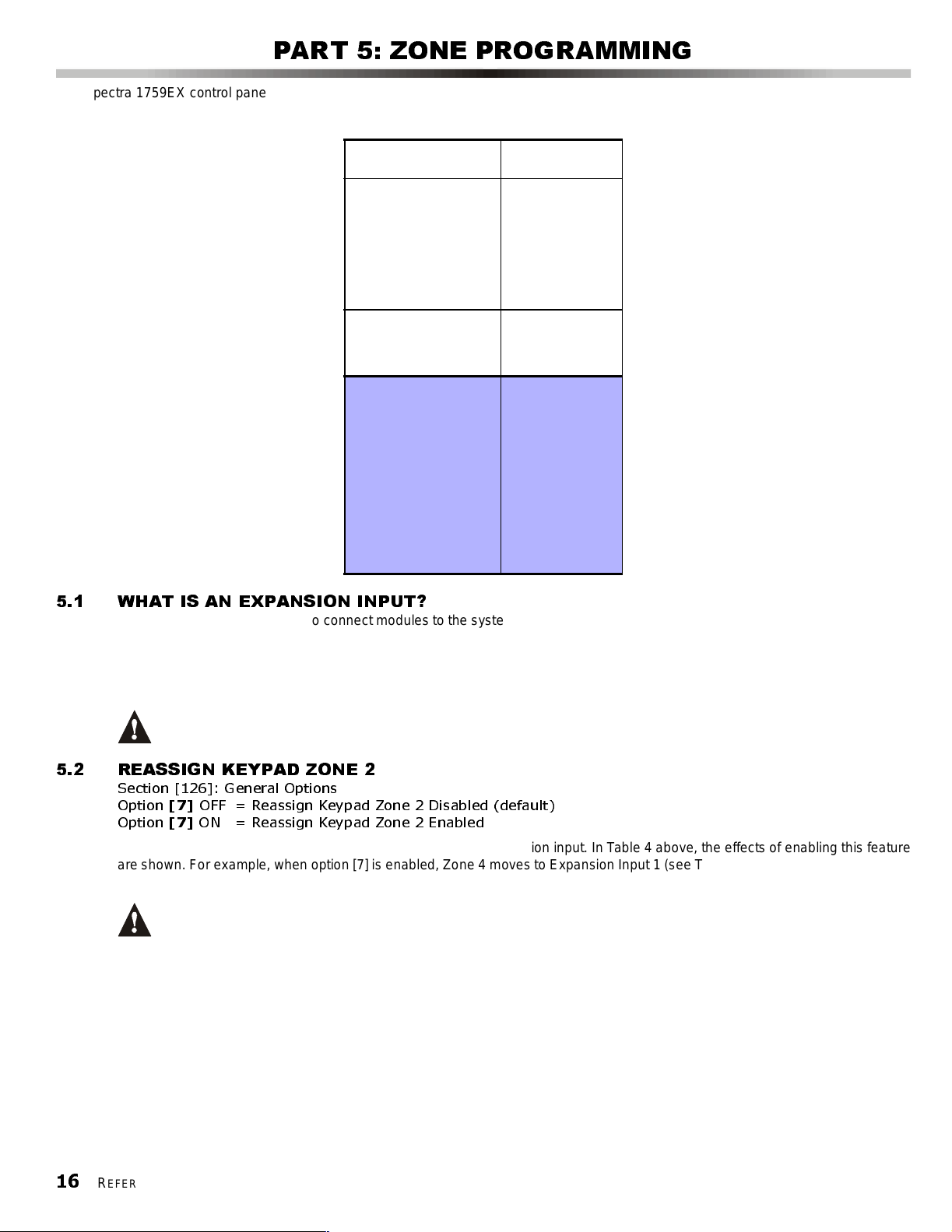
5.1 WHAT IS AN EXPANSION INPUT?
An expansion input al lows you to con nect modules to the system to increase the number of zones available up to 15 zones. Each
hardwired input on a zone expansion bus module or wireless transmitter can be assigned to an expansion input. The expansion
inputs can be used in any combination. For example, 5 wireless transmitters and 3 hardwire inputs can be assigned to the
expansion inputs. Spectra control panels cannot support more than eight expansion inputs. Refer to the appropriate module’s
Instruction Sheet for detail s.
Do not assign inputs from diff erent modules to the same expansion input.
5.2 REASSIGN KEYPAD ZONE 2
Section [126]: General Options
Option
Option
Reassign Keypad Zone 2 changes the keypad zone in to an expansion i nput. In Table 4 above, the effects of enabl ing this feature
are shown. For example, when option [7] is enabled, Zone 4 moves to Expansio n Input 1 (see Table 5 on page 17). Then, you are
able to use Expansi on Input 1.
[7]
OFF = Reassign Keypad Zone 2 Disabled (default)
[7]
ON = Reassign Keypad Zone 2 Enabled
When Reassign Keypad Zone 2 is enabled, the Keypad Tamper Supervision (see page 42) for keypad zone 2 is
lost. Keypad Tamper Supervision will
ONLY fu nction on Keypad Zone 1.
16
REFERENCE & INSTALLATION MANUAL
Page 19

5.3 REASSIGN ZONES TO EXPANSION INPUTS
Section [126]: General Options
Option
Option
Reassign Zones to Expansion Inputs changes the zone numbering to increase the number of expansion inputs that can be
displayed on 10-Zone LED Keypads. In installations that require using mostly the expansion inputs, such as using wireless
zones, the 10-Zone LED Keypads may be unable to display some of the zones. In the following table, the effects of enabling this
feature and Reassign Keypad Zone 2 ( see section 5.2 on page16) are shown:
[8]
OFF = Reassign Zones to Expansion Inputs Disabled (default)
[8]
ON = Reassign Zones to Expansion Inputs Enabled
Control Panel
Input 1 =
Input 2 =
Input 3 =
Input 4 =
Input 5 =
Keypad
Zone 1 =
Zone 2 =
Expansion
Input 1 =
Input 2 =
Input 3 =
Input 4 =
Input 5 =
Input 6 =
Input 7 =
Input 8 =
Table 5:
Option [8 ]:
OFF
1759EX 1759EX 1759EX 1759EX
Option [8 ]:
ON
Zone Display with 10-Zone LED Keypad
Option [8]: ON and
Option [7]: OFF
(Reassign Keypad Zone 2)
Option [8]: ON and
Option [7]: ON
Zone 1 Zone 1 Zone 1 Zone 1
Zone 2 Zone 2 Zone 2 Zone 2
Zone 3 N/A N/A N/A
Zone 4 N/A N/A N/A
Zone 5 N/A N/A N/A
Zone 6 Zone 3 Zone 3 Zone 3
Zone 7 Zone 4 Zone 4 N/A
Zone 8 Zone 5 Zone 5 Zone 4
Zone 9 Zone 6 Zone 6 Zone 5
Zone 10 Zone 7 Zone 7 Zone 6
Zone 11 Zone 8 Zone 8 Zone 7
Zone 12 Zone 9 Zone 9 Zone 8
Zone 13 Zone 10 Zone 10 Zone 9
Zone 14 Zone 11 Zone 11 Zone 10
Zone 15 Zone 12 Zone 12 Zone 11
(Reassign Keypad Zone 2)
= not displayed on 10-Zone LED Keypads
5.4 ZONE PROGRAMMING
After connecting a hardwired detection device to one of the control panel's or zone expansion bus module’s input terminals or
after setting up any wireless transmitters, define the associated zone's parameters. The Zone Parameters define the type of
zone, the zone's partition assignment and how the control panel will react when an alarm condition occurs on that zone. These
Zone Parameters are prog ramm ed into one section as det ailed in Figure 5.1 on page 18.
Only on-board zones 01 to 04 can be defined as a Fire, Fire Delayed or a Keyswitch zone. On-board zone 05
cannot
be programmed as such.
S
PECTRA
1759EX
17
Page 20

Figure 5.1: Spectra Zone Programming
Keypad s be ep twice
Press the
[
ENTER] key
Enter the
[
INSTALLER CODE]
[001] = Zone 1 [009] = Zone 9
[002] = Zone 2 [010] = Zone 10
[003] = Zone 3 [011] = Zone 11
[004] = Zone 4 [012] = Zone 12
[005] = Zone 5 [013] = Zone 13
[006] = Zone 6 [014] = Zone 14
[007] = Zone 7 [015] = Zone 15
[008] = Zone 8
Zone Definitions
1 - Entry Delay 1
2 - Entry Delay 2
3 - Follow
4 - Instant
5 - 24Hr. Burglary
6 - 24Hr. Buzzer
Additiona l defin iti on s for
on-board terminals:
7 - Keyswitch
8 - 24Hr. Fire
9 - 24Hr. Delayed Fire
5.5 ZONE DEFINITIONS
As demonstrated in Figure 5.1, sections [001] to [015] represent zones 1 through 15 respectively, where the first digit in each of
these sections represents the zone's definition. Also, refer to Zone Speed on page 22. To disable a zone, clear the contents of
the section corresponding to the desired zone by pressing the [
Zone Definitions, which are described as follows.
Select
one
Key in 3-digit
[
SECTION]
Zone Definition
First Digit
Zone Partition
Assignment
Second Digit
Zone Options
Feature Select
Press [ENTER]
Zone Partition Assignment
1 - Zone Assi gn ed to Pa rt i tio n 1
2 - Zone Assi gn ed to Pa rt i tio n 2
3 - Zone Assigned to both Partitions
Select
one
[1] Auto Zone Shutdown Enabled
[2] Bypas s Enabled
[3] Stay Zone
[4] [5] Zone Alarm Type
OFF OFF Audible Alarm (steady)
OFF ON Audible Alarm (pulsed)
ON OFF Silent Alarm
ON ON Generates only a report
[6] Intel l izone
[7] Delay alarm transmission
[8] Force Z o ne
Zone Options
Keyswitch Options
[1] OFF= Maintained
ON = Momentary
[2] OFF = Regular Arm
ON = Stay Arm
FORCE] key 3 times and pressing [ENTER]. There are 9 available
18
REFERENCE & INSTALLATION MANUAL
5.5.1 ENTRY DELAY 1
Sections [001] to [015]: Zones 1 to 15, First Digit =
When the system is armed and a zone define d wit h Entry Delay 1 opens, t he control panel wi ll generate an alarm after
the programmed Entry Delay 1 Tim er elapses. This is to provide users with enough time to enter the protected area
and disarm the system. To program the Entry Delay 1 Timer, key in the desired 3-digit delay value (000 to 255
seconds, Default = 45 secon ds) into section [069]. Entry Delay zones are commonly used at the entry/ exit points of the
protected area (i.e. front/back door, garage, etc.). Using different Entry Delays (see Entry Delay 2) is useful when, for
example, one entry point requires a longer delay than the other entry point or in a partitioned system where each
partition may require a different Entry Delay.
5.5.2 ENTRY DELAY 2
Sections [001] to [015]: Zones 1 to 15, First Digit =
Entry Delay 2 zones are identical to t he Entry Delay 1 zones (see section 5.5.1), except it uses a separate Entry Delay
Timer. To program the Entry Delay 2 Timer, key in the desired 3-digit delay value (000 to 255 seconds, Default = 45
seconds) into section [070].
This timer is also used as the St ay Delay timer (see section 7.2).
1
2
Page 21

5.5.3 FOLLOW ZONES
Sections [001] to [015]: Zones 1 to 15, First Digit =
When an armed Follow Zone opens, the control panel will imme diately generate an alar m , unless an Entry Delay zone
opens first:
• If an armed Follow Zone opens after an Entry Del ay zone opens, the control panel waits until the Entry De lay Timer
has elapsed before generating an alarm.
• If an armed Follow Zone opens after more than one Entry Delay zone opens, the control panel will wait until the
Entry Delay Timer of the zone that opened first has elapsed.
This feature is commonly used when a motion detector is protecting the area occupied by the entry point keypad. This
will prevent the motion detector from causing an alarm when a user enters through the entry point to disarm the
system.
5.5.4 INSTANT ZONES
Sections [001] to [015]: Zones 1 to 15, First Digit =
When an armed Instant Zone opens, the control panel immediately generates an alarm. Instant Zones are commonly
used for windows, patio doors, skyli ghts and other perimeter type zones.
5.5.5 24HR. BURGLARY ZONES
Sections [001] to [015]: Zones 1 to 15, First Digit =
Whenever a 24Hr. Burglary Zone opens, whether the system is armed or disarmed, the control panel will immediately
generate an alar m.
5.5.6 24HR. BUZZER
Sections [001] to [015]: Zones 1 to 15, First Digit =
Whenever a 24Hr. Buzzer Zone opens, whether the zone is armed or disarmed, the cont rol panel sets off the keypads’
buzzers to indicate that the zone was breached. The control panel will report the alarm, but will not enable the bell/
siren output. Enter any valid access code on the keypad to stop the buzzer. This zone definition is particularly useful
when a user wishes to be notified when something such as a safe or locker within the home has been accessed (i.e. a
child accessi ng a valuable collection).
3
4
5
6
5.6 EXCLUSIVE ZONE DEFINITIONS
The following three zone definitions can only be used for devices connected directly to the control panel’s on-board input
terminals. W hen a zone is programmed as a Keyswitch Zone, the c ontrol pane l will ignore all other Zone Options. When a zon e is
programmed as a Standard Fire Zone or Delayed Fire Zone, the control panel will ignore the Zone Options that may have been
programmed, except Auto Zone Shutdown. Wireless devices and devices connected to the zone expansion bus modules cannot
be programmed with these defini tions.
5.6.1 KEYSWITCH ZONE
Sections [001] to [004]: Zones 1 to 4, First Digit =
Connecting a keyswitch to a zone allows users to arm the system by pressing a button or by turning a switch on or off
with a key. Please refer to Keyswitch Connections on page 10 and to Keyswitch Options on page 21.
5.6.2 STANDARD 24HR. FIRE ZONE
Sections [001] to [004]: Zones 1 to 4, First Digit =
Whenever a Standard 24Hr. Fire Zone opens, whether it is armed or disarmed, the control panel will generate the
following:
• The control panel can send the corresponding Alarm Report Code f rom sections [187] to [190].
• If a tamper/wiring fault occurs on a Fire Zone, the control panel can send a Fire Loop Trouble report code
programmed in section [206] to the Central Station. The keypads will di splay a Fire Loop Trouble in their Trouble
Display (see page 47).
• Alarms are always audible regardl ess of other settings . Fi re alarms generate an interm ittent (pulsed) bell/siren
output signal as show n in Fi gure 5.2 on page 20.
For information on how to connect smoke detectors to the control pa nel, refer to Fire Circuits on page 10.
5.6.3 DELAYED FIRE ZONE
Sections [001] to [004]: Zones 1 to 4, First Digit =
When a Delayed 24Hr. Fire Zone opens, whether it is armed or disarmed, the control panel will react as shown in
Figure 5.3 on page 20. Delayed 24Hr. Fire Zones are commonly used in residential homes where a smoke detector
often generat es fal se alarms (i.e. burn ing bread, etc.).
7
8
9
S
PECTRA
1759EX
19
Page 22

5.7 ZONE PARTITION ASSIGNMENT
Figure 5.2: Bell Output During Fire Ala rm
Figure 5.3: Delayed 24Hr. Fire Zone
Sections [001] to [015]: Zones 1 to 15
The control panel provides the option of partitioning the security system
into two completely independent systems. As demonstrated in Figure 5-1
on page 18, sections [001] to [015] represent zones 1 through 15
respectively, where the second digit in each of these sections represents
the zone's partition assignment. The zone is assigned to Partition 1 if
second digit = 1, Partition 2 if second digit = 2, or both partitions is
second digit = 3. For deta i ls on Partitioning, refer to page 41.
5.8 ZONE OPTIONS
As demonstrated in Figure 5.1, sections [001] to [015] represent zones 1
through 15 respectively. After entering the first two digits, select one or
more of the following Zone Options by using the Multiple Fe ature S elect
Programming Method (see page 11):
5.8.1 AUTO ZONE SHUTDOWN
Section s [001] to [015] = Zones 1 to 15
Option
Option
If, in a single armed per iod, the number of alar ms generated by
a zone with the Auto Zone Shutdown option enabled exceeds
the number defined by the Auto Zone Shutdown Counter, the
control panel will no longer generate an alarm for that zone. To
program the Auto Zone Shutdown Counter, key in the desired
limit (000=Disabled, 001 to 015, Default = 5) into section [089].
The Auto Zone Shutdown Counter resets every time the
system is armed.
[1]
OFF = Auto Zone Shutdown Disabled
[1]
ON = Auto Zone Shutdown Enabled for
selected zone (default)
5.8.2 BYPASS ZONES
Section s [001] to [015] = Zones 1 to 15
Option
Option
When a user, utilizes the Bypass Programming feature (see page 49), only zones with the Bypass option enabled can
be programmed as bypas sed.
[2]
OFF = Byp as s Zon e Disabl ed
[2]
ON = Selected Zone is Bypass Enabled (default)
Do not program a Fire Zone with the Bypass opti on, as the control panel will never bypass Fire Zones.
5.8.3 STAY ZONES
Sections [001] to [015]: Zones 1 to 15
Option
Option
Zones with the Stay option enabled will be bypassed when the system is Stay Armed (see page 49).
[3]
OFF = Stay Zon e Disab led (defa u lt)
[3]
ON = Selected Zone is Stay Enabled
Do not program a Fire Zone with the Stay option, as the control panel will never bypass Fire Zones
when Stay Arming.
5.8.4 ALARM TYPES
Sections [001] to [015]: Zones 1 to 15
[4] OFF / [5] OFF: Audible Steady (default)
When the conditions for an alarm have been met, the control panel can transmit the appropriate Zone Alarm report
code (see page 33) and provides a steady output for any bells or sirens connected to the control panel’s bell output.
20
REFERENCE & INSTALLATION MANUAL
Page 23
[4] OFF / [5] ON: Audible Pulsed Alarm
When the conditions for an alarm have been met, the control panel can transmit the appropriate Zone Alarm report
code (see page 33) and provides a pulsed output (see Figure 5-2 on page 20) for any bells or sirens connected to the
control panel’s bell output.
[4] ON / [5] OFF: Silen t Alarm
When the conditions for an alarm are met, the control panel can transmit the appropriate Zone Alarm report code (see
page 33) and will not activate the control panel’s bell output. The appropriate
flash to indicate an alarm and the user will still have to disarm the system .
[4] ON / [5] ON: Report Only
When the conditions for an alarm have been met, the control panel can transmit the appropriate Zone Alarm report
code (see page 33). The system will not have to be disarmed.
5.8.5 INTELLIZONE
Sections [001] to [015]: Zones 1 to 15
Option
Option
This featur e reduces the possibil ity of false alarms. When a zone with the Intellizone option opens, the panel does not
immediately generate an alarm. First it triggers the Intell izone Delay Timer. T o program the I ntellizone Del ay Timer, key
in the desired 3-digit value (010 to 255 seconds, Default = 48 seconds) into section [084]. If any of the following
conditions occur during this period, the panel will generat e an alarm:
• During the Intellizone Delay, a second zone has caused an alarm.
• During the Intellizone Delay, the zone in alarm has restored (clos ed) and re-occurred (opened).
• The zone in alarm remains open for the entire Intellizone Delay.
[6]
OFF = Intellizone Disabled (default)
[6]
ON = Intellizone Enabled for Selected Zone
5.8.6 DELAY BEFORE ALARM REPORT CODE TRANSMISSION
Sections [001] to [015]: Zones 1 to 15
Option
Option
When an alarm condition occurs on a zone with this option enabled, the cont rol panel en ables the bell/ siren output, but
does not report the alarm to the central station until the end of the Alarm Before Transmission Delay. To program the
Alarm Transmission Delay, key in the desired 3-digit delay value (000 = Disabled, 001 to 255 seconds) into section
[080]. During this period, disarming the system di sables the b ell /siren output and cancel s the report code transmiss ion.
This feature is commonly used with Entry Delay zones to reduce false alarms created by new users who may not
disarm the sy stem in time.
[7]
OFF = Delay Alarm Transmission Disabled (default)
[7]
ON = Delay Alarm Transmission Enabled for Selected Zone
ARM or STATUS LED on the keypads will
5.8.7 FORCE ZONES
Sections [001] to [015]: Zones 1 to 15
Option
Option
Any open Force Zones at the time of arming will be c onsidered deactivated b y the contr ol panel (see page 49). If
during this period a deactivated zone is closed, the control panel will revert that zone to active status. Consequently,
the control p anel will generate an alarm if the zone is breached.
[8]
OFF = Force Zone Disabled (default)
[8]
ON = Selected Zone is Force Enabled
Do not program a Fire Zone with the Force option, as the control panel will never bypass Fire Zones
when Force Arming.
5.8.8 KEYSWITCH OPTIONS
Sections [001] to [004]: Option [1] and [2]
When an on-board zone is programmed as a Keyswitch Zone (see section 5.6.1 on page 19), the control panel will
ignore any other Zone Option. The keyswitch can be programmed as a Maintained or Momentary Keyswitch and to
Regular or Stay Arm (see section 13.4 on page 48). A Maintained Keyswitch will arm the system when it is set to the
ON position and will disarm when set to the OFF position. To arm with a Momentary Keyswitch, set the keyswitch to the
ON position then turn it back to the OFF position. Repeating this sequence will disarm the system. Program the
keyswitch with the f ollowing:
Option [1] OFF = Maintained (default) Option [2] OFF = Regular Arming (default )
Option [1] ON = Momentar y O ption [2] ON = Stay Arming
S
PECTRA
1759EX
21
Page 24

5.9 ZONE SPEED
Sections [050] to [064]: Zones 1 to 15
001 to 255 X 10ms, Default = 600ms
The Zone Speed defines how quickly the control panel will respond to an open zone. The control panel will not display an open
zone on the keypad or generate an alarm until the programmed Zone Speed has elapsed. All other zone definitions and options
do not come into effect until the Zone Speed has elapsed. This feature prevents any momentary glitches from causing an alarm
or unnecessary reporting.
5.10 E O L Z O N E S
Section [132]: Zone Options
Option
Option
If all detection devices connec ted to the control panel have i nput termina ls that require 1KΩ end of line resistors, enable opt ion [4]
in section [13 2]. For details on using EOL res istors, refer to see Single Zone Inputs on page 9.
[4]
OFF = Zones do not use EOL resistors (default)
[4]
ON = Zones require EOL resisto rs
PART 6: WIRELESS ZONE PROGRAMMING
The Spectra 1759EX allows for the addition of up to eight fully supervised Omnia wireless transmitters, and up to eight programmable
remote controls.
6.1 WIRELESS TRANSMITTER PROGRAMMING
The programming of the wireless transmitters (detector s and door contacts) is accomplished in two steps:
1. Assign the wirele ss transmitter to the Spectra 1759EX.
2. Program the zones.
6.1.1 ASSIGNING WIRELESS TRANSMITTERS TO THE RECEIVER
Sections [601] to [608]
Sections [601] to [608] represent expansion inputs 1 to 8 respectively. For example, section [601] is assigned to
expansion input 1, section [602] is assigned to expansion input 2, etc. (refer to Table 6). Each Expansion Input
represents a specific zone in the Spectra 1759EX system (see Zone Recognition Table on page 16).
Table 6:
Section # 6-digit Serial Number Exp ansion Input
[601] ___/___/___/___/___/___ Input 1
[602] ___/___/___/___/___/___ Input 2
[603] ___/___/___/___/___/___ Input 3
[604] ___/___/___/___/___/___ Input 4
[605] ___/___/___/___/___/___ Input 5
[606] ___/___/___/___/___/___ Input 6
[607] ___/___/___/___/___/___ Input 7
[608] ___/___/___/___/___/___ Input 8
How Do I Assign Wireless Transmitters to the Spectra 1759EX?
1) Press the [ENTER] key.
2) Enter your [
3) Enter the desired [
4) Enter the 6-digit [
Do not assign detection devices from different modules to the same expansion input. For example, do
not assign a wireless transmitter to secti on [601] and then connect a detection device to input Z1 of the
APR3-ZX8.
The serial number is located on the inside of the transmitter or you can use the Serial Number Display (refer to
section 6.3 on page 23) to determine its serial number.
The transmitters must be activated once having been assigned to the Spectra 1759EX. To activate a
transmitter, insert the batteries and close the cover. To ensure proper synchronization between the control
panel and the tra nsm itter, open and close the zone corresponding to the tra nsm itter.
INSTALLER CODE].
SECTION NUMBER] (from sections [601] to [608]).
SERIAL NUMBER] of the wireless transmitte r.
Sections and Expansion Inputs
22
REFERENCE & INSTALLATION MANUAL
Page 25

6.1.2 DELETING ASSIGNED WIRELESS TRANSMITTERS
Sections [601] to [608]
How Do I Delete Assigned Wireless Transmitters?
1) Press the [ENTER] key.
2) En ter you r [
3) Enter the desired [
4) Press the [0] key six times to clear the serial number.
INSTALLER CODE].
SECTION NUMBER] (from sections [601] to [608]).
6.1.3 PROGRAMMING THE ZONES
The zones allocated to the wireless transmitters must be programmed. Refer to Zone Programming on page 16 for
more information.
6.2 VIEWING THE WIRELESS TRANSMITTER SIGNAL STRENGTH
Sections [631] to [638]
Once wireless transmitters have been installed and assigned to the Spectra 1759EX, the signal strength of each transmitter can
be verified in sections [631] to [638]. Each section represents the signal strength viewer for a specific device. For example,
section [631] is the viewer for the device in section [601] and section [638] is the viewer for the device in section [608]. Please
note that this feat ure only works wi th wirel ess tra nsmitt ers assi gned to an Expa nsi on Input (zone) as desc ribed i n sectio n 6.1.1 on
page 22. A reading of 1 is the weakest and a reading of 8 is the strongest. An average reading of 3 and up is acceptable.
Sometimes moving the tr ansm itter or control panel by a small amount will greatly increase th e signal reception.
How Do I View a Wireless Transmitter’s Signal Strength?
1) Press the [ENTER] key.
2) Enter your [
3) Enter the desired [
4) Press the transmitter’s tamper swi tch or open the correspondi ng zone.
5) On an LED keypad: The keypad will ill u m in a te num b ers 1 to 8.
On an LCD keypad: The keypad will display numbers from 1 to 8 on the screen. For example, the LCD screen below
shows a signal strength reading of 5.
INSTALLER CODE].
SECTION NUMBER] (fr om secti ons [631] to [638]).
After entering the desi red section, ignore the first reading as it will not be accurate.
You can al so use a beep sequence feature to verify a transmitter’s signal streng th. When you press a transm itter’s tamper switch,
beep tones emanating from all the keypads connected to the communication bus will advise you of the transmitter’s signal
strength.
How Do I Attain a Wireless Transmitter’s Signal Strength using the Beep Sequence?
1) Press the [ENTER] key.
2) Enter your [
3) Enter the desired [
4) Press the transmitter’s tamper swi tch or open the correspondi ng zone.
5) Listen for the beep tones:
If the signal strength is less than 3 = One beep
If the signal stre ngth is between 3 and 6 = Two beeps
If the signal stre ngth is greater than 6 = Three beep s
This feature cannot be used with any remote controls assigned to the control panel.
INSTALLER CODE].
SECTION NUMBER] (f rom sections [631] to [6 38]).
6.3 SERIAL NUMBER DISPLAY
Section [630]
This feature will display the serial number of any wireless transmitter on any Spectra keypad.
How Do I Vi ew a Transmitter’s Seri al Nu m ber?
1) Press the [ENTER] key.
2) Enter your [
3) Enter the section [630].
4) Press the [0] key six times to clear the serial number.
INSTALLER CODE].
S
PECTRA
1759EX
23
Page 26
5) On an LED Keypad: The serial number digits will appear one at a time by illum inating the corresponding LED light. To
view the next digit, press the [
On an LCD Keypad: The first three digi ts of the serial number wil l appear. Press the [
next three digits.
6.4 SUPERVISION OPTIONS
The Supervision Options cannot be used wi th any remot e controls assigned to the control panel.
6.4.1 CHECK-IN SUPERVISION
Section [610]: Supervision Options
Option
Option
Option [1] enables the Check-in Supervision feature. The Spectra 1759EX waits for each of its assigned wireless
transmitters to send a status signal within a specified time period (as programmed in section 6.4.2) to confirm their
presence and functionality. If a device has not sent a signal within that time period, the Spectra 1759EX can generate
a trouble, an alarm, and/or transmit a report code to the monitoring station (refer to Wireless Transmitter Supervision
Options on page 44).
6.4.2 CHECK-IN SUPERVISION TIMER SETTINGS
Section [610]: Supervision Options
Option
Option
Option
Option
Options [2] and [5] define the time period that the control panel will expect a check-in status signal from its assigned
wireless transmitters. For example, if the timer is set to 12 min. (option [5] = OFF; option [2] = ON), the control panel
will expect a check-in status signal to be sent from its assigned wireless transmitters every 12 minutes. If the Spectra
1759EX does not receive a signal from one of its wireless transmitters within the period defined here, the Spectra
1759EX can then generate a trouble, an alarm, and/or can transmit a report code to the monitoring station (refer to
Wireless Transmitter Supervision Options on page 44) . Refer to section 6.4.1 on page 24 for instructions on enabling
check-in sup ervision.
[1]
OFF = Check-in supervision disabled (default)
[1]
ON = Check-in supervision enabled
[2]
OFF = Check-in supervision base time setting in Hours (default)
[2]
ON = Check-in supervision base time setting in Minutes
[5]
OFF = Check-in supervision time value set to 12 (default)
[5]
ON = Check-in supervision time value set to 6
Options [2] and [5] mus t match the jumper settin gs of the assigned tr ansmitters. For examp le. if the
check-in supervision is set for every 12 hours, the transmitters’ jumper settings must be set to 12 hours.
ENTER] key .
ENTER] key three times to view the
6.4.3 LOW BATTERY SUPERVISION
When the battery voltage of a wireless transmitter (motion detector or door contact) drops below a certain value, the
Spectra 1759EX will send a low battery rep ort code to the monitoring station, and a tr ouble will appear in the keypad’s
trouble display.
Section [129] option [6] must be enabled in order for Low Battery Supervision to work. For more
information, refer to Wireless Transmitter Low Battery Supervision on page 44.
6.5 REMOTE CONTROL PROGRAMMING
The Spectra 1759EX accept s up to eight fully programmable remote controls. Programming the remot e controls is accomplished
in three step s:
1. Assign the remote controls to the Spectra 1759EX control panel.
2. Assign the remot e controls to User Access Codes.
3. Program the buttons on the remote controls.
The remote control will transmit a signal for only 1 second when a button is pressed. This is done to conserve the remote
control’s batteries.
6.5.1 REMOTE CONTROL ASSIGNMENT MODE
Section [650]: Option
Option
Option
Though both the Parakey and Omnia remote controls are compatible with the Spectra 1759EX, all eight remote
controls allowable per 1759EX must be of the same type (Omnia or Parakey). Disabling option [8] configures the
[8]
OFF = The Spectra 1759EX is configured to use Omnia (OMN-RCT1) remote controls
[8]
ON = The Spectra 1759EX is configured to use Parakey (344) remote controls
[8]
(default)
24
REFERENCE & INSTALLATION MANUAL
Page 27

Spectra 1759EX to accept transmissions from an Omnia remote control only. Enabling option [8] configures the
Spectra 1759EX to accept transmissions from a Parakey remote control only.
6.5.2 ASSIGNING A REMOTE CONTROL TO THE SPECTRA 1759EX
Sections [731] to [738]: Remote Controls 1 to 8 respectively
Remote controls are assigned to the module using the Automatic Learning me thod.
How Do I Assign a Remot e Con trol to the Spectra 1759EX?
1) Press the [ENTER] key.
2) Enter your [
3) Enter the desired [
4)
Press any button on the remote control twice or until the confirmation beep sounds (“Beep-Beep-Beep-Beep-Beep”)
INSTALLER CODE].
SECTION NUMBER] (from sections [731] to [738]).
If you are having trouble assigning the remote control, the environment may be too noisy. Therefore,
we recommend that you assign the remote controls before instal ling the transmitters.
6.5.3 DELETING ASSIGNED REMOTE CONTROLS
Sections [731] to [738]: Remote Controls 1 to 8 respectively
How Do I Delete a Remote Control?
1) Press the [ENTER] key.
2) En ter you r [
3) Enter the desired [
4) Press the [
INSTALLER CODE].
SECTION NUMBER] (from sections [731] to [738]).
FORCE] button.
6.5.4 ASSIGNING REMOTE CONTROLS TO USER ACCESS CODES
Sections [701] to [708]: Remote Controls 1 to 8 respectively
Each remote control must be assigned to a User Access Code. All User Access Codes are given a User Number from
001 to 048. Enter the desired User Number in a section from [701] to [708] that represent the remote control assigned
in sections [731] to [738] (refer t o section 6.5.2 on page 25). For example, the remote control assigned in section [731]
will be assigned to th e User Access Code designated in sect ion [701].
.
How Do I Assign a Remo te Cont r ol to a User Acc ess C ode ?
1) Press the [ENTER] key.
2) En ter you r [
3) Enter the desired [
4) Ente r th e [
INSTALLER CODE].
SECTION NUMBER] (from sections [701] to [708]).
USER NUMBER] to be assigned to the remote control (001 to 048).
6.5.5 PROGRAMMING THE REMOTE CONTROL BUTTONS
Sections [711] to [718]: Remote Controls 1 to 8 respectively
Each remote control can be programmed to perform up to 8 different actions. Each digit in sections [711] to [718]
represents a button or combination of buttons (refer to Table 7 on page 26). When a user arms or disarms using the
remote control , t he control panel will arm or disarm all the areas assigned to the User Access Code (see sect ion 6.5.4
on page 25). Sections [711] to [718] represent the remote controls assigned to sections [731] to [738] (refer to section
6.5.2 on page 25). For example, the buttons for the remote control assigned in section [731] will be programmed in
sectio n [7 11].
How Do I Program the Re m ote Control’s Button s?
1) Press the [ENTER] key.
2) En ter you r [
3) Enter the desired [
4) Enter the [
to Table 7). If you do not wish to program all the buttons or button combi nati ons, si mply press t he [
any time to save and exit.
The User Code assigned to the remote control (refer to section 6.5.4 on page 25) must have the same
User Options enabled. For example, if you enable the Force Ar ming button option, you must enable the
appropriate Force Arming user option. Also, if you enable any Panic button options, you must enable
the Panic options in the control panel (refer to section 8.4 on page 30)..
INSTALLER CODE].
SECTION NUMBER] (from sections [711] to [718]).
HEXADECIMAL VALUE] (0 to D) of the desired b utton option fro m Table 8 in the appropriate space (refer
ENTER] key at
S
PECTRA
1759EX
25
Page 28
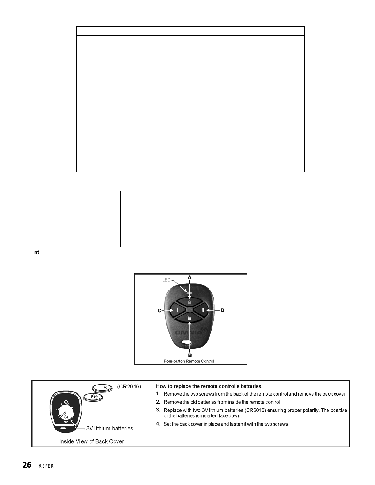
T able 7:
Remote Control Button Prog ramm ing (refer to Table 8)
Section
[711] ____/____/____/____/____/____/____/____
A B C D A+B C+D A+C B+D
[712] ____/____/____/____/____/____/____/____
A B C D A+B C+D A+C B+D
[713] ____/____/____/____/____/____/____/____
A B C D A+B C+D A+C B+D
[714] ____/____/____/____/____/____/____/____
A B C D A+B C+D A+C B+D
[715] ____/____/____/____/____/____/____/____
A B C D A+B C+D A+C B+D
[716] ____/____/____/____/____/____/____/____
A B C D A+B C+D A+C B+D
[717] ____/____/____/____/____/____/____/____
A B C D A+B C+D A+C B+D
[718] ____/____/____/____/____/____/____/____
A B C D A+B C+D A+C B+D
Remote Control Button Programming
Remote Control # 1
Remote Control # 2
Remote Control # 3
Remote Control # 4
Remote Control # 5
Remote Control # 6
Remote Control # 7
Remote Control # 8
T able 8:
[
FORCE] = Bu tton D isabl e d [7] = Regular Arm and Disarm
[1] = Regular Arm [8] = Generate a Panic 1 Alarm (Police)
[2] = Stay Arm [9] = Generate a Panic 2 Alarm (Medical)
[3] = In s tant Arm [A] = Generate a Panic 3 Alarm (Fire)
[4] = Force Arm [B] = Activates any PGMs that have Event Group #07 * as their Activation Event
[5] = Disarm [C] = Activates any PGMs that have Event Group #08 * as their Activation Event
[6] = Disarm when ther e is no al arm [D] = Activates any PGMs that have Event Group #09* as their Activat ion Event
* Event Group #07, #08 and #09 (Button Pressed on Remote) of the Spectra 1759EX PGM Table. For the PGM Table, please refer to the Spectra
1759EX Programming Guide (1759EX-EP).
Figure 6.1: Remote Control Button Identification
Button Options
26
REFERENCE & INSTALLATION MANUAL
Figure 6.2: Replacing the Remote Control’s Bat teries
Page 29

PART 7: ARMING AND DISARMING OPTIONS
7.1 SWITCH TO STAY ARMING
Section [133] = Partition 1, Section [134] = Partition 2
Option
Option
If a user Regular arms a partition, but does not exit through (open and close) an Entry Delay zone during the Exit Delay, the
control panel can be programmed to switch from Regul ar Arming to Stay Arming.
7.2 STAY ARMING WITH DELAY
Section [133] = Partition 1, Section [134] = Partition 2
Option
Option
When a partition is Stay Armed when this feature is enabled, all the zones in the partition, except 24Hr. zones, are associated
with the Stay Delay. Therefore, the control panel wi ll not generate an alarm i f a zone i s breached unt il the Stay Delay has elapsed.
This feature prevents false alarms by allowing users enough time to disarm their system if a zone is accidentally triggered. For
example, if a user opens an armed window or crosses an armed detector on the way to the kitchen in the middle of the night, the
user will have enough time to disarm the system before the alarm is generated. Each partition’s Stay Delay follows the value
programmed in Entry Del ay Timer 2 in section [070].
[4]
OFF = Switch to Stay Arming Disabled (default)
[4]
ON = Switch to Stay Arming Enabled
[5]
OFF = Stay Arming with Delay Disabled (default)
[5]
ON = Stay Arming with Delay Enabled
7.3 REGULAR ARMING SWITCHES TO FORCE ARMING
Section [131]: Arming/Disarming Options
Option
Option
With this feature enabled, the control panel will always Force arm instead of Regular arm when a valid User Access Code with
the Force Arming Option is entered. In installations where the user must always Force arm when leaving the protected area, this
feature allows users to For ce arm wit hout pressing the [
[2]
OFF = Regular Arming Switches to Force Arming Disabled (default)
[2]
ON = Regular Arming Switches to Force Arming Enabled
FORCE] key before entering t heir User Access Code.
7.4 RESTRICT ARMING ON BATTERY FAIL
Section [130]: Arming/Disarming Options
Option
Option
If this option is enabled, the control panel will not arm the system if the control panel detects that the backup battery is
disconnected, that its fuse is blown, or that the battery voltage drops to less than 10.5V. The control panel will not arm the system
until all battery tr ouble conditions are rectified.
[5]
OFF = Permit arming on battery failure (default)
[5]
ON = Restrict arming on battery failure
7.5 RESTRICT ARMING ON TAMPER FAILURE
Section [130]: Arming/Disarming Options
Option
[6]
OFF = Permit arming on tamper failure (default)
Option
If this option is enabled, the control panel will not arm the system if the control panel detects a tamper trouble on one or more
zones. The control panel will not arm the system until all tamper trou ble conditions are rectified.
[6]
ON = Restrict arming on tamper failure
This feature will not function if the Tamper Recognition Options (see page 30) are disabled or whenever the
tampered zone is bypassed and the Tamper Bypass Options (see page 30) have been enabled.
(NOT TO BE USED WITH UL INSTALLATIONS)
7.6 TIMED AUTO-ARMING
Section [133] = Partition 1, [134] = Partition 2
Option
Option
Each partition can be programmed to arm every day at the time specified by the Auto-Arm Timer. The Auto-Arming Options (see
section 7.8) determine the partition's arming method. Any open zones detected when a partition is Auto-Armed will be by pass e d
regardless of their definition (except 24hr. zones). The control panel will enter a 60-second Exit Delay period before arming the
system. At this point, Auto-Arming can be cancelled by entering a valid access code. Once the partition has successfully armed,
the control panel can transmit the Timed Auto-Arming report code programmed in section [172].
Example: To automatically arm part it ion 2 everyday at 6:15PM, enable Timed Auto-Arming for partition 2 by turning on option [1]
in section [134]. Then key in 18:15 into section [112].
[1]
OFF = Timed Auto-Arming Disabled (default)
[1]
ON = Timed Auto-Arming Enabled
S
PECTRA
1759EX
27
Page 30
7.6.1 AUTO-ARM TIMER
Section [111] = Partition 1, [112] = Partition 2
Select the section corresponding to the desired partition and program the time (use the 24-hour clock i.e. 6:30PM =
18:30) that you wish the control panel to attempt to arm the selected partition and/or send the Late to Close report
code. If Timed Auto-Arming is disabled, the control panel will still send the Late to Close report code at the time
specified by the Auto-Arm Timer.
7.7 NO MOVEMENT AUTO-ARMING
Section [133] = Partition 1, [134] = Partition 2
Option
Option
If no movement occurs in a partition's protected area for the period specified by the No Movement Timer (see below), the control
panel can automatically arm that partition. The Auto-Arming Option described in section 7.8 of this manual determines the
partit ion's arming method. Any o pen zones detected when a partition is Auto-Armed will be by passed regardless of their definition
(except 24hr. zones). Upon arming, the control panel will transmit the No Movement report code if programmed in section [172].
Regardless of whether the system was successfully armed or not, the control panel will always transmit the No Movement report
code if programmed in section [172]. If No Movement Auto-Arming is disabled, the control panel will still send the No Movement
report code at the time specified by the No Movement Timer.
Example: To arm partition 1 whenever there is no movement for a period of 4 hours, enable No Movement Auto-arming for
partit ion 1 by turning on the [2] Opti on in section [133]. Then in sect ion [075] enter 016 (16x15min. = 240min. = 4 hours).
7.7.1 NO MOVEMENT TIMER
[2]
OFF = No Movement Auto-Arming Disabled (default)
[2]
ON = No Mo vemen t Auto -Armin g En ab led
Section [075] = Partition 1, [076] = Partition 2
001 to 255 x15min., Default = disabled
Select the section corresponding to the desired partition and program the interval of time without movement you wish
the control panel to wait before arming and/or sending the No Movement report code. If No Movement Auto-Arming is
disabled, the control panel can still send the No Movement report code when no movement has been detected for the
period specified by the No Movement Timer.
7.8 AUTO-ARMING OPTIONS
Section [133] = Partition 1, [134] = Partition 2
Option
Option
When using Tim ed Auto-Ar ming or No Movemen t Auto-Arm ing (see secti on 7.6 and secti on 7.7), the control panel can Regul ar or
Stay Arm (see page 48) the selected partition.
7.9 ONE-TOUCH ARMING
Section [130]: Options [1] to [4]
Option
Option
Option
Option
The One-touch Arming features allow users to arm the system without having to enter any access codes. To arm the system,
press and hold the appropriate key (see a bove) for approximately 2 seconds. If the sy stem is part it ioned (see page 41), you must
also press the key corresponding to the partition you wish to arm. For more information on the different arming methods, please
refer to page 48.
[3]
OFF = Regula r Armin g (defa u lt)
[3]
ON = Stay Arming
(NOT TO BE USED WITH UL INSTALLATIONS)
[1]
ON = Press & hold the
[2]
ON = Press & hold the
[3]
ON = Press & hold the
[4]
ON = Press & hold the
7.10 EXIT DELAY
Section [071] = Partition 1, [072] = Partition 2
001 to 255 seconds, Default = 30 seconds,
After entering the required arming sequence (i.e. User Access code, etc.), the Exit Delay parameter determines the amount of
time a user has to leave the protected area before the control panel arms the partition. The Exit Delay applies to all zones in the
selected partition. When enabled, the keypad will beep once every second during the Exit Delay and will beep rapidly during the
final 10 seconds of the Exit Delay.
(NOT TO BE USED WITH UL INSTALLATIONS)
[ENTER]
[STAY]
[FORCE]
[BYP]
key for One-touch Regular Arming.
key for One-touc h Stay Armin g.
key for One-touch Force Arming.
key for One-touc h By pas s Pro gramm in g.
Maximum 60 seconds for UL Listed systems
7.10.1 BEEP ON EXIT DELAY
Section [130]: Arming/Disarming Options
Option
Option
28
REFERENCE & INSTALLATION MANUAL
[8]
OFF = Beep on Exit Delay Disabled
[8]
ON = Beep on Exit Delay Enabled (default)
Page 31
7.11 BELL SQUAWK ON ARM/DISARM WITH KEYPAD
Section [130]: Arming/Disarming Options
Option
Option
When this feature is enabl ed, the bell or siren will squawk once upon arming and twice upon di sarming.
[7]
OFF = Bell Squawk on Arm/Disarm Disabled (default)
[7]
ON = Bell Squawk on Arm/Disarm Enabled
7.12 BELL SQUAWK ON ARM/DISARM WITH REMOTE CONTROL
Section [131]: Arming/Disarming Options
Option
Option
When this feature is enabled, the bell or siren wil l squawk once upon ar m ing with a remote cont rol and twice upon disarming with
a remote control. Must be enabled for UL installations.
[3]
OFF = Bell Squawk on Arm/Disarm with Remote Control Disabled (default)
[3]
ON = Bell Squawk on Arm/Disarm with Remote Control Enabled
7.13 NO EXIT DELAY WHEN ARMING WITH REMOTE CONTROL
Section [131]: Arming/Disarming Options
Option
Option
When the option is enabled, the panel cancels the Exit Delay (arms instantly) when a partition is armed with a remote control.
When disabled, the Exit Del ay ti m er will start when a part ition is armed with a remote cont rol.
[4]
OFF = Provides Exit Delay When Arming with a Remote Control (default)
[4]
ON = No Exit Delay When Arming with a Remote Control
7.14 NO EXIT DELAY BEEPS AND NO BELL SQUAWK WHEN STAY ARMING
Section [131]: Arming/Disarming Options
Option
Option
With this feature enable d, the control panel will prevent t he bell or siren from s quawking and the keypads from beeping during the
Exit Delay, whenever a par ti ti on is Stay Armed.
[5]
OFF = No Exit Delay Beeps and No Bell Squawk When Stay Arming Disabled (default)
[5]
ON = No Exit Delay Beeps and No Bell Squawk When Stay Arming Enabled
8.1 BELL CUT-OFF TIMER
Section [073] = Partition 1, [074] = Partition 2
000 = Disabled, 001 to 255 minutes, Default = 4 minutes,
After an audible alarm, the bell or siren will stop upon disarming of the partition or when the Bell Cut-Off Timer has elapsed,
whichever comes first.
8.2 RECYCLE ALARM
After the Bell Cut-Off Timer and the Recycle Delay have elapsed, the control panel will re-verify the zone status. If there are any
open zones, the control panel will generate another alarm. In one armed period, the control panel will repeat this sequence the
number of times defined by the Recycle Counter.
8.2.1 RECYCLE ALARM DELAY
Section [090]
000 = disabled, 001 to 255 minutes, Default = disabled
The Recycle Delay determines the amount of time after Bell Cut-Off that the control panel will wait before re-verifying
zone status.
8.2.2 RECYCLE COUNTER
Section [091]
000 = disabled, 001 to 255, Default = disabled
The Recycle Counter determines the number of times the control panel will re-verify the zone status after Bell Cut-Off
in one armed period.
PART 8: ALARM OPTIONS
5 minutes minimum for ULC installations
S
PECTRA
1759EX
29
Page 32

8.3 TAMPER RECOGNITION
Section [132]: Zone Options
[1] OFF / [2] OFF: T am per Recognition Disabled (default)
If the system is armed or disarmed
an alarm. This option is not permitted on UL systems.
[1] OFF / [2] ON: Trouble Only
If the system is armed
(see page 20).
in the keypads’ Tr ouble Display (see page 47) and the control panel will transmit the appropriate Zone Tamper report code (see
page 34).
[1] ON / [2] OFF: Silen t Alarm
If the system is armed
(see page 20). In a disarmed system, it functions the same as the Trouble Only setting, but it will also generate a silent alarm. A
silent alarm will not trigger any bells or sirens, but the system will have to be disarmed.
[1] ON / [2] ON: Audible Alarm
In an armed system and a tamper wiring failure occurs on a zone, the control panel will follow the zone's Alarm Types setting
(see page 20). In a disarmed system, it functions the same as Trouble Only setting, except it will also generate an audible
alarm.
If the system is disa rme d
8.3.1 TAMPER BYPASS OPTIONS
Section [132]: Zone Options
Option
Option
With option [3] on, the Tamper Recognition feature follows the zone bypass definition. This means the control panel
will ignore any tampers detected on a bypassed zone. With option [3] off, Tamper Recognition ignores the bypass
definition. This means the control panel will generate an incident as per Tamper Recognition settings if a tamper or
wire fault occurs on a bypassed zone.
and a tamper wiring failure occurs on a zone, the control panel will follow the zone's Alarm Types setting
and a tamper wiring failure occurs on a zone, the control panel will follow the zone's Alarm Types setting
[3]
OFF = Will generate a tamper if detected on a bypassed zone (default)
[3]
ON = Tampers on bypassed zones will be ignored
, the control panel will display the zone as open in the keypad display, but will no t generate
and a tamper wiring fai lure occ urs on a zone, a Tamper/Zone Wiring Failur e will appear
8.4 KEYPAD PANIC OPTIONS
Section [128]: General Options
Option
Option
Pressing the [1] and [3] keys simultaneously on the keypad for 2 seconds will generate a silent or audible alarm as defined by
option [4].
Option
Option
Pressing the [4] and [6] keys simultaneously on the keypad for 2 seconds will generate a silent or audible alarm as defined by
option [5].
Option
Option
Pressing the [7] and [9] keys simultaneously on the keypad for 2 seconds will generate a silent or audible alarm as defined by
option [6].
Option
Option
Option
Option
Option
Option
Silent alar m
The control panel emits a Confirmation Beep a nd transmit s the appropriate Panic report code if programmed in section [195]. The
control pan el wi ll not enable the keypad buzzers or the control pa nel’s
[1]
OFF = Emergency Panic Disabled (default)
[1]
ON = Emergency Panic Enabled
[2]
OFF = Auxiliary Panic Disabled (default)
[2]
ON = Auxiliary Panic En ab led
[3]
OFF = Fire Panic Disabled (default)
[3]
ON = Fire Panic Enabled
[4]
OFF = Emerge ncy Panic is Silent (default)
[4]
ON = Emergency Pan ic is Audible
[5]
OFF = Au xili ary Pani c is Sile nt (defa ul t)
[5]
ON = Au xili ary Pani c is Aud ibl e
[6]
OFF = Fire Panic is Silent (default)
[6]
ON = Fire Panic is Pulsed
:
BELL output (no audible alarm).
Audible alarm
Same as silent alarm , except the keypad buz zers and the
valid User Access Code or when the Bell Cut-Off Timer elapses (see page 29).
Fire (pulse d) alarm
Same as audible operat ion, except that the
30
REFERENCE & INSTALLATION MANUAL
:
BELL output will activ ate until a user cancels the al arm (disarms) with a
:
BELL output will be pulsed as shown in Figure on page 20.
Page 33

Whether the system is partitioned or not, the control panel will report all panic alar m s to partition 1.
8.5 PANIC LOCKOUT TIMER
Section [094]
When a panic alarm is activated, the control panel can ignore the disar m signal from a remote control for a specified period. This
prevents an aggressor from disarming the system by remote cont rol during a panic situation . In section [094] enter a 3-digit va lue
(000 to 255, 000 = disabled) representing the number of seconds that the remote cont rols will be locked out of t he system.
S
PECTRA
1759EX
31
Page 34

PART 9: REPORTING AND DIALER SETTINGS
[6] = Pager
[4] = Ademco Express
]
“Programmable”
t
Pulse
The following section explains all the features and options that must be programmed in order for your security system to properly report
system events to a central station. When an event (e.g. zone in alarm) occurs in the system, the control panel verifies if a report code was
programmed in the section corresponding to the event (except Ademco Contact ID “All Codes”). If a report code was programmed, the
control panel will dial the central station telephone number defined by the Event Call Direction feature. When the central stat ion answers,
the control p anel will transmit the System Account Code, followed by the programmed Report Code.
Figure 9.1: Event Reporting
Reporting/Dialer
Option [3] - Section [135]
Partition Account
Numbers
Partition 1
Partition 2
Centr al Station Telephone Numbers 1 & 2
Sections [151] & [152]
Back-up Number
Section [153]
Central Station Telephone Numbers 1 & 2
Defines which Central Station Telephone Numbers each group of
events will report to.
Section [137]
Option [1] ON = Ca ll Telephone #1 for Arm/Disarm Report Cod es
Option [2] ON = Ca ll Telephone #2 for Arm/Disarm Report Cod es
Option [3] ON = Ca ll Telephone #1 for Alarm/Restore Report Codes
Option [4] ON = Ca ll Telephone #2 for Alarm/Restore Report Codes
Option [5] ON = Call Telephone #1 for Tamper/Restore Report Codes
Option [6] ON = Call Telephone #2 for Tamper/Restore Report Codes
Section [138]
Option [1] ON = Call T elephone #1 for Trouble/Restore Report Codes
Option [2] ON = Call T elephone #2 for Trouble/Restore Report Codes
Option [3] ON = Call Telephone #1 for Special System Report Codes
Option [4] ON = Call Telephone #2 for Special System Report Codes
Partition Account Number 1
3 or 4 digits (0- F) in section [143]
Parti tion Account Number 2
3 or 4 digits (0- F) in section [144]
Related Featur e s
Delay Before Alarm Transmission
Section [080]
Pager F ormat Delay Transmission
Section [083]
Recent Closing Delay
Section [085]
Power Failure Report Delay
Section [086]
Auto Test Report
Sections [087] & [110]
Report Disarm Options
Option [1] - Section [131]
Report Zone Restore Options
Option [6] - Section [132]
Alternate Dial
Option [4] - Section [136]
Maximum Dialing Attempts
Section [081]
32
REFERENCE & INSTALLATION MANUAL
Reporting Formats
Section [140]
st
1
digit = CSTN#1
nd
2
digit = CSTN#2
DTMF
(Tone)
[1] = Ademco Slow
[2] = Silent Knight Fas
[3] = Sescoa
[5] = Ademco Contact ID
Progr am 1 or 2- digit
(1 - FF) report codes
into sections [160]
to [213] where each
section represents
up to fo ur events in
the system.
“Programmable”
Option [3]
Option [3] ON - Section [136
OFF - Section [136
Delay between Dialing
Attempts
Section [136]
Program the 2-digit report codes
corresponding to the Contact I.D.
Table in to sections [160] to [213]
where each section represents
up to four ev ents in the system.
Program FF to use the default
Contact ID Report Code.
The control panel
automatically generates
all report codes. You do
not have to program
any report codes.
Page 35
9.1 REPORTING/DIALER (ENABLE/DISABLE)
Section [135]: Dialer Options
Option
Option
[3]
OFF = Reporting /Dialer Disabled (default)
[3]
ON = Reporting/Dialer Enabled
9.2 REPORT CODES
A report code is a 1- or 2-digit hexadecimal value consisting of digits from 1 to F. Each sect ion from [160] to [213] represents a set
of up to four specific events and each of these events can be programmed with a separate 1- or 2-digit report code.
Only the Ademco Slow, Silent Knight, Sescoa and Pager Formats support 1-digit report codes. To program a 1digit report code, press the [
When a specific event occurs, the control panel will attempt to transmit the programmed report code to the central station. The
method of report code transmission is defined by the Reporting Formats (see page 35) and the Event Call Direction (see
page 37). These two items define how and where the report codes are transmitted. If you are using the Ademco Contact ID “All
Codes” format, sections [160] to [213] do not have to be programmed. For more information, refer to Reporting Formats (see
page 35). The following sub-sections provide a brief descr iption of the event s that the control pane l can report.
9.2.1 ARMING REPORT CODES
Sections [160] to [171]
A report code can be programmed for each of the 48 User Access Codes. When using an access code to arm a
partition, the control panel can send the appropriate report code to the central station, identifying which access code
was used to arm the partit ion.
9.2.2 SPECIAL ARMING REPORT CODES
Sections [172] and [173]
Whenever the system is armed using one of the special arming features listed below, the control panel can send the
appropriate report code to the central station identifying how the system was armed.
Section [172]
•TIMED AUTO-ARMING: A partition has armed it self at the programmed time (see page 27).
•L
ATE TO CLOSE: Reports every day at the time specified by the Auto-Arm Timer (see page 28).
• N
O MOVEMENT: A partition has armed itself after the programm ed period without movement (s ee No Movem ent
Arming on page 28).
• P
ARTIAL ARMING: A partition was Stay, Instant or Force Armed or armed with Bypassed zones.
Section [173]
• ONE-TOUCH ARMING: A partition was armed using a One-touch Arming feature (see page28).
• R
EMOTE ARMING: A partition was armed using the Winload software.
• K
EYSWITCH ARMING: A partition was armed using a keyswitch (se e page19)
• Future use
FORCE] key followed by the desired hexadecimal digit or vice versa.
9.2.3 DISARMING REPORT CODES
Sections [174] to [185]
A report code can be pr ogrammed for each of the 48 User Access Codes. Whenever an access code is used to disarm
an armed partition or a partition in alarm, the control panel can send the appropriate report code to the central station,
identifying which access code was used to disarm the partition.
The Disarming and the Special Disarming report codes can be transmitted every time a partition is disarmed or
only when a partition is di sarmed after an alarm (see Disarming Reporting Option s on page 38 ).
9.2.4 SPECIAL DISARMING REPORT CODES
Section [186]
Whenever using one of the special disarming features, the control panel can send the report code to the central
station, identifying how the sy stem was disarmed.
• C
ANCEL AUTO-ARM: A par ti tion is disar m ed during the Timed Auto-Arm 's 60-second Exit Delay (see page 27). Only
reports if Disarming Reporti ng Options (see page 38) are set to always report disarming.
• R
EMOTE DISARM: System is disarmed using the Winload software.
• K
EYSWITCH DISARMING: System disarmed using a keys wit ch (see page 19).
• Future use
9.2.5 ZONE ALARM REPORT CODES
Sections [187] to [190]
A report code can be programmed for each of the 15 available zones. Whenever a zone generates an alarm, the
control panel can send the appropriate report code to the cent ral station, ident if ying which zone generated an alarm.
S
PECTRA
1759EX
33
Page 36

9.2.6 ZONE ALARM RESTORE REPORT CODES
Sections [191] to [194]
A report code can be programmed for each of the 15 available zones. The control panel can transmit these report
codes to the central station identifying which zone was restored.
A zone is restored when it closes after generating an alarm or once the bell has cut-off after alarm generation.
Please refer to Zone Restore Report Options on page 38.
9.2.7 SPECIAL ALARM REPORT CODES
Sections [195] and [196]
Whenever the system generates an alarm due to one of the conditions listed below, the control panel can send the
appropriate report code to the central station identifying the type of alarm.
Section [195]
• EMERGENCY PANIC: Panic keys [1] and [3] have been pressed (see page 30).
• A
UXILIARY PANIC: Panic keys [4] and [6] have been pressed (see page30).
• F
IRE PANIC: Panic keys [7] and [9] have been pressed (see page 30).
• R
ECENT CLOSING: Reports when an alarm is generated after arming the s ystem within period defined by the Recen t
Close Delay (see pa ge38).
Section [196]
• AUTO ZONE SHUTDOWN: A zone communicates more than the programmed number of transmissions in a single
armed period (see page 20).
• D
URESS: A Duress access code is keyed in (see page 15).
• K
EYPAD LOCKOUT: If a consecu ti ve number of invalid codes are ent ered into a keyp ad, the control panel can be set
to deny access from all keypads for a specified period.
• Future use
9.2.8 ZONE TAMPER REPORT CODES
Section [197] to [200]
A report code can be programmed for each of the 15 available zones. Whenever a tamper or wire fault occurs on a
zone, the control panel can send the appropriate report code to the central station identifying which zone was
tampered.
9.2.9 ZONE TAMPER RESTORE REPORT CODES
Sections [201] to [204]
A report code can be programmed for each of the 15 available zones. Whenever a tampered zone is restored, the
control panel can send the appropriate rep ort code to the central station identifying which zone has been restor ed.
If Tamper Recognition (see page 30) is disabled, the control panel will not report the occurrence of any
tampers , w ire fa u lts or tamper restores.
9.2.10 SYSTEM TROUBLE REPORT CODES
Section [205] to [207]
Whenever the system generates one of the instances listed below, the control panel can send the appropriate report
code to the central station identi fyi ng the type of system troubl e.
Section [205]
• Future use
• AC F
• B
• A
Section [206]
• BELL OUTPUT OVERLOAD: Bell/siren output has over loaded (see page 8).
• B
• T
• F
Section [207]
• WIRELESS LOW BATTERY: The battery voltage of an Omnia wireless transmitter (motion detector or contact switch)
• M
• P
• F
AILURE: The control panel has detected a loss of AC power. Transmission of this report code can be delayed
(see Power Failure Report Delay on page 38).
ATTERY FAILURE: backup battery is disconnec ted or battery volt age is ≤10.5V.
UXILIARY SUPPLY: Auxiliary power supply has overloaded (current consumption is >1.1A).
ELL OUTPUT DISCONNECTED: Devices connected to the Bell Output have been disconnected.
IMER LOSS: The control panel has detected a loss in time or clock failure (see page41)
IRE LOOP TROUBLE: The control panel has detected a tamper trouble on a fire zone.
has dropped below recommended limits.
ODULE FAULT: Will repo rt if all keypads con nect ed to the cont rol pa nel have been di sco nnected or if a module with
its corre sponding supervision option enabled in th e control panel (see pages 43 and 44) is disconnect ed.
RINTER FAULT: An error has occurred on the Printer Module.
AIL TO COMMUNICATE: The control panel has failed all attempts to communic ate with the central station. The report
code will be transmitted upon the next successful attempt.
34
REFERENCE & INSTALLATION MANUAL
Page 37

9.2.11 SYSTEM TROUBLE RESTORE CODES
Sections [208] to [210]
Whenever the system restores one of the troubles listed in section 9.2.10, the control panel can send the appropriate
report code to the central stat ion identifying the type of system trouble restore. If Telephone Line Monitoring is enabled
(see page38), the control panel can also transmit a TLM Restore report code.
9.2.12 SPECIAL REPORTING CODES
Sections [211] to [213]
Whenever the system generates one of the instances listed below, the control panel can send the appropriate report
code to the central station identi fying the type of system occurrence.
Section [211]
• COLD START: The control panel was completely shutdown (no battery, no AC) and then was re-started.
• T
EST REPORT: A test report has been generated automatically (see pa ge38).
• Not available
• P
C EXIT: The control panel has ended communication with WinLoad.
Section [212]
• INSTALLER IN: Installer has entered the programming mode.
• I
NSTALLER OUT: Installer has exited the programming mode.
• Future use
• Future use
Section [213]
• TX SUPERVISION LOSS: Wireless Transmitte r Supervision (see SPC-319 Instruction Sheet) has been enabled and a
transmitter is no longer communicating with the system.
• T
X SUPERVISION RESTORE: Reports when the above trouble has been restored
• Future use
• Future use
9.3 CENTRAL STATION TELEPHONE NUMBERS
Section [151] = Phone#1, [152] = Phone#2, [153] = Backup Phone#: Up to 32 digits
The Spectra Control Panels can dial up to 2 different central station telephone numbers. You can enter any digit from 0 to 9 and
any special keys or functions (see Table 9) up to a maximum of 32 digits. For more inf ormation on how these tel ephone numbers
are used, please refer to Event Call Direction on page 37 and Reporting Formats in section 9.5. After the Maximum Dialing
Attempts (see page 37) to one central station telephone num ber have failed, the control p anel will then dial the backup telephone
number. If the Alternate Dial Option (see page 38) is enabled, the control panel will dial the programmed backup telephone
number after every failed attempt. If no backup telephone number is programmed, the control panel will never report to the
backup telephone number. Also refer to Delay Between Dialing Attempts on page 38.
T able 9:
Special Keys for Telephone Numbers
Press Action or Value
[
STAY] *
BYP] #
[
MEM] switch from pulse to tone dialing or vice versa
[
TBL] or [TRBL] 4-second pause
[
FORCE] deletes current digi t
[
PG] or [FNC1] inserts bl ank space
[
9.4 PARTITION ACCOUNT NUMBERS
Section [143] = Partition 1, [144] = Partition 2
All report codes are preceded by a 4-digit or 3-digit Partition Account Number to ensure correct identification in a partitioned system.
Partitio n account numb ers can be an y hexa-digit fr om 1 to F. To en ter a 3-digit acco unt number, simpl y press the [
follo wed by the 3-digit accoun t number. Also, when using 3-d igit a ccount numbers, yo u must use 1-digit r eport c odes.
FORCE] key
9.5 REPORTING FORMATS
Section [140]: 1st digit = Format for Phone #1, 2nd digit = Format for Phone #2
The Spe ctra Cont rol Pan els can use a nu mber of d ifferent rep orting f ormats and each Ce ntral Station Telephone Numb er can be
program med with a differ ent reporting form at. The first digit entered into sec tion [140] represents the r eporting forma t used to
communicate with Central Station Telephone Number 1, the second digit represents the reporting format used to communicate with
Central Station Telephon e Numb er 2. The Backup Telephone Nu mber uses the sa me rep orting fo rmat as the last C entral Station
Telephone Number t hat was dialed.
S
PECTRA
1759EX
35
Page 38
Value Entered Reporting Format
1 Ademco Slow (1400Hz, 1900Hz, 10BPS)
2 Silent Knight Fast (1400Hz, 1900Hz, 10BPS)
3 SESCOA (2300Hz, 1800Hz, 20BPS)
4 Ademco Express (DTMF 4+2)
5 (Default) Ademco Contact ID
6 Pager Format
If Hexadecimals (0 to FF) are used to program the report codes, verify that the pager also supports
Hexadecimals. If the pager does not support Hexadecimals, use only the digits 0 to 9.
UL Note: The installer is required to verify the complete compatibility of the DAC Receiver and formats at least
once per year.
9.5.1 STANDARD PULSE FORMATS
The Spectra Control Panels can use t he Ademco slow, Silent Knight and Sescoa standard pul se reporting formats (see
Table 10 above).
9.5.2 ADEMCO EXPRESS
The Ademco Express is a high-speed reporting format, which will transmit the 2-digit (11 to FF) report codes
programmed into sections [160] to [213]. Unlike ot her Ademco formats , t he Adem co Express does not use the Contact
ID Report Codes.
9.5.3 ADEMCO CONTACT ID
Ademco Contact ID is a fast communicator format that uses tone reporting instead of pulse reporting. This communicator
format also uses a pre-defined list of industry stan dard messages and report codes that will suit most of your basic
installation needs. Please refer to the Contact ID Report Codes List in the Programming Guide for a complete list of these
report codes and messages.
T able 10:
Reporting Formats
9.5.4 CONTACT ID OPTIONS
Section [136]: Dialer Options
Option
Option
When using the Programmable Codes format, use the Ademco Contact ID Report Codes List in the Spectra System
Programming Guide (version 2.0 or higher) to program the desired report codes into sections [160] to [213]. Enter FF
to use the default Contact ID Report Codes. Press the [
format, the control panel will automatic ally generate Cont act ID Repor t Codes for every event in secti ons [160] to [213].
Refer to the “All Codes” Ademco Contact ID Report Code List in the Spec tra System Programming Guide.
[3]
[3]
When using the Ademco Contact ID Programmable format, both telephone numbers must use this
reporting format.
9.5.5 PAGER REPORTING FORMAT
Section [136]: Dialer Options
[6]
OFF /
[6]
OFF /
[6]
ON /
[6]
ON /
Using this format allows the control panel to transmit report codes to a pager or a cellular telephone. Since the control
panel cannot confirm whether the transmission was successful or not, it can be programmed to call the pager or
cellular telephone up to four times and transmit the report codes each time. To ensure that the report is received, the
control panel transmits the account number, the report code and the # sign four times during each call. Also, refer to
the P a ger Del a y in sec tion 9 .6.
9.6 PAGER DELAY
Section [083]
001 to 255 seconds, default = 5 seconds
When using the Pager Reporting Format (see section 9.5.5), the control panel will wait for the Pager Delay period before
transmitting the report codes. This is to allow time for the pager system to provide a dial tone or to bypass the “welcome”
message before sending data.
OFF = Pro gramm ab le Cod es
ON = All Codes (default)
[7]
OFF: 1 call to the pager/cellular telephone
[7]
ON: 2 calls to the pager/cellular telephone
[7]
OFF: 3 calls to the pager/cellular telephone
[7]
ON: 4 calls to the pager/cellular telephone
FORCE] key to enter a 0 value. When using the All Codes
36
REFERENCE & INSTALLATION MANUAL
Page 39
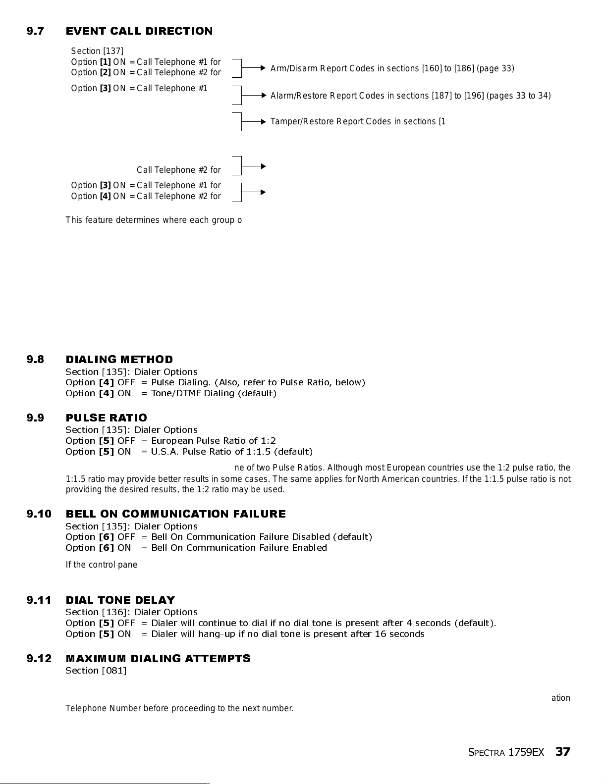
9.7 EVENT CALL DIRECTION
Section [137]
Option [1] ON = Call Telephone #1 for
Option [2] ON = Call Telephone #2 for
Option [3] ON = Call Telephone #1 for
Option [4] ON = Call Telephone #2 for
Option [5] ON = Call Telephone #1 for
Option [6] ON = Call Telephone #2 for
Section [138]
Option [1] ON = Call Telephone #1 for
Option [2] ON = Call Telephone #2 for
Option [3] ON = Call Telephone #1 for
Option [4] ON = Call Telephone #2 for
This feature determines where each group of events will be reported. The control panel events are divided into five groups (see
above) where each event group can be programmed to dial one or both Central Station Telephone Numbers. When a reportable
event occurs in the system, the control panel will verify that one of the two telephone numbers has been enabled. The control
panel will begin by dialing the selected telephone number(s). If both numbers were selected it will begin with Central Station
T el epho ne Number 1. Afte r the Maximum Dialing Attempts (see page 37) to one central stati on telepho ne number have fai led, the
control panel will then dial the backup telephone number. If the Alternate Dial Option (see page 38) is enabled, the control panel
will dial the programmed backup telephone number after every failed attempt. If no backup telephone number is programmed,
the control panel will never report to the backup telephone number. Also, refer to Delay Between Dialing Attempts on page 38.
Example: The system is armed and zone 1 has been breached caus ing an alarm. If option [3] is off and opti on [4] is on in section
[137], the control panel will attempt to communicate with Central Station Telephone Number 2 in order to transmit the Zone 1
Alarm Report Code programmed in sect ion [187].
Arm/Disarm Report Codes in sections [160] to [186] (page 33)
Alarm/Restore Re port Codes in sections [1 87] t o [196] (pages 33 to 34)
Tamper/Restore Report Codes in sections [197] to [20 4] (page 34)
Trouble/Restore Report Codes in sections [205] to [ 210] (pages 34 to 35)
Special Report Codes in sections [211] to [213] (page 35)
9.8 DIALING METHOD
Section [135]: Dialer Options
Option
Option
[4]
OFF = Pulse Dialing. (Also, refer to Pulse Ratio, below)
[4]
ON = Tone/DTMF Dialing (default)
9.9 PULSE RATIO
Section [135]: Dialer Options
Option
Option
When using Pulse dialing, you can select one of t w o Pulse Ratios. Although most European countries use t he 1:2 pulse ratio, the
1:1.5 ratio m ay provide better result s in some cases. The s am e applies for North American countries. If the 1: 1.5 pulse ratio is not
providing the desired results, the 1:2 ratio may be used.
[5]
OFF = Euro pean Pulse Ratio of 1:2
[5]
ON = U.S.A. Pulse Ratio of 1:1.5 (default)
9.10 BELL ON COMMUNICATION FAILURE
Section [135]: Dialer Options
Option
Option
If the control panel fails to communicate with the central station when the system is armed, it will enable the BELL output, sett ing
off any bells or sirens connected to the output.
[6]
OFF = Bell On Communication Failure Disabled (default)
[6]
ON = Bell On Communication Failure Enabled
9.11 DIAL TONE DELAY
Section [136]: Dialer Options
Option
Option
[5]
OFF = Dialer will continue to dial if no dial tone is present after 4 seconds (default).
[5]
ON = Dialer will hang-up if no dial tone is present after 16 seconds
9.12 MAXIMUM DIALING ATTEMPTS
Section [081]
001 to 016 attempts, Default = 8 attempts
The value programmed in section [081] determines how many times the control panel will re-dial the same Central Station
Telephone Number before proceeding to the next number.
S
PECTRA
1759EX
37
Page 40

9.13 DELAY BETWEEN DIALING ATTEMPTS
Section [082]
000 to 255 seconds, Default = 20 seconds
This delay determ ines the amount of time the control panel will wait between eac h dial ing attempt.
9.14 ALTERNATE DIAL OPTION
Section [136]: Dialer Options
Option
Option
With option [4] OFF, the control panel will dial the backup telephone number programmed in section [153] after all attempts to
one Central Station Telephone Number have failed (see section 9.12). With option [4] ON, the control panel will dial the backup
telephone number after every failed attempt.
[4]
OFF = Alternate Dial Disabled (default)
[4]
ON = Alternate Dial Enabled
9.15 RECENT CLOSE DELAY
Section [085]
000 to 255 seconds, Defau lt = no delay
If after having ar med the syste m, an alarm is gen erated wi thin the peri od defi ned by the Recent Close Delay, the control panel will
attempt to transm it the Recent Close report code programmed in section [195].
9.16 AU TO TEST REPORT
Sections [087]
000=disabled, 001 to 255 days, Default = disabled
Section [110]: Time (HH:MM)
The control panel will transmit the Test Report report code programmed into section [211] after the number of days programmed
into section [087] has elaps ed at t he time programmed int o section [110]. Use the 24-hour clock to program the time (i.e. 6:30PM
= 18:30). The first Test Report will be transmit ted within 24 hours after the feature is enabled at the time programmed in [110].
Example: Section [087] = 005 and section [110] = 13:00. The first Test Report will be sent at 1 PM that day and then the report
will be sent every 5 days at 1 PM.
9.17 POWER FAILURE REPORT DELAY
Section [086]
001 to 255 minutes, Default = 15 minutes
The control panel will transmit the AC Failure report code programmed in section [205] after the Power Failure Report Delay
period has elapsed.
9.18 DISARM REPORTING OPTIONS
Section [131]: Arming /Disarming Options
Option
Option
With option [1] OFF, the control panel will send the Disarming report codes (see page 33) to the central station every time the
system is disarmed. With option [1] ON, the control panel will send the Disarming report codes to the central station when the
system is disarmed following an alarm.
[1]
OFF = Alw ays Report Disarmin g
[1]
ON = Report Disarming Only After Alarm (default)
9.19 ZONE RESTORE REPORT OPTIONS
Section [132]: Zone Options
Option
Option
With option [6] OFF, the control panel will send the Zone Alarm Restore report codes (see page 34) to the central station when
the zone has returned to normal and the Bell Cut-O ff Timer has elapsed (see page 29). With option [6] ON, the control panel will
send the Zone Alarm Restore report codes to the central station as soon as the zone returns to normal or when the system is
disarmed.
[6]
OFF = Report On Bell Cut-Off (default)
[6]
ON = Report On Zone Closure
9.20 TELEPHONE LINE MONITORING (TLM)
When enabled, the system verifies the existence of a telephone line once every second. A line test failure occurs when the TLM
detects less than 3 volts for the period defined by the TLM Fail Timer. If the line test fails, the control panel’s
and generates one or more conditions as defined by the TLM settings below. These will be restored when the control panel
detects the telephone line again. Please note that when the diale r detects an incoming cal l, the TLM test will stop for 1 minute.
STATUS LED flashes
38
REFERENCE & INSTALLATION MANUAL
Page 41
Section [135]: Dialer Options
[1] OFF / [2] OFF: TLM Disabled
[1] OFF / [2] ON: Trouble Only
Upon line test failure, a TLM Trouble will appear in the keypads’ Trouble Display (see page 47).
[1] ON / [2] OFF: Alarm If System Armed
Upon line test failure, a TLM Trouble will appear in the keypads’ Trouble Display (see page 47) and if the system is armed, the
control panel wil l generate an alarm.
[1] ON / [2] ON: Silent Alarm Becomes Audible
Upon line test failure, a TLM Trouble will appear in the keypads’ Trouble Display (see page 47) and causes a silent zone or silent
panic alarm to switch to audible.
9.20.1 TLM FAIL TIMER
Section [079]
016 to 255 x 2 seconds, Defaul t = 32 seconds
If TLM does not detect the existence of a telephone line for the duration of this period, the control panel will generate
the condition(s) defined by the TLM optio ns (see above).
PART 10: PROGRAMMABLE OUTPUTS
A PGM is a programmable output that toggles to its opposite state (i.e. a normally open PGM will close) when a specific event has occurred
in the system. For example, a PGM can be used to reset smoke detectors, activate bells or strobe lights, open/close garage doors and
much more. When a PGM closes, the control panel supplies a ground to the PGM activating any device or relay connected to it. When a
PGM opens, the circuit opens from ground, theref ore, cutting power to any devices connected to it.
PGM1
A programmable output tha t provides
up to 150mA.
Refer to
Alarm Relay and PGMs on page 8.
PGM2
PGM2 is a programmable output that can provide up to 2.5A. PGM2 is designed to be used as a Strobe Output. For information refer to
PGM Strobe Options on page 40. For connections, refer to Alarm Relay and PGM s on page 8.
Global PGM
The Global PGM allows you to use the control panel’s PG M Event List to activate PGMs located on a modul e or LCD keypad. For example,
if you enable a module’s “Follows Global PGM” option, the PGM on the module will activate whenever the event programmed in section
[124] occurs. Every PGM on every keypad and/or expansion bus module can be programmed to follow the event(s) defined by the Global
PGM.
10.1 PGM ACTI VATION EVENT
Sections [120], [122], and [124]
This feature all ows you to progr am the control panel to activat e a PG M when a specific event occurs in th e system. The PGM will
remain in its active state until the programmed PGM Deactivation Event occurs or when the PGM Delay period elapses (see
page 40). For the Event List see the PGM Table in the Spectra 1759EX Programming Guide. To program a PGM Activation
Event:
1) Enter section that represents the desired PGM. PGM1 = [120], PGM2 = [122], Global PGM = [124]
2) Enter the Event Group #.
3) Enter the Sub- G roup #.
4) Enter the Partition #
01 = Partit io n 1
02 = Partit io n 2
99 = Both Partitions
The “AC Loss” PGM Event will only occur after the Power Failure Report Delay elapses (see page 38).
S
PECTRA
1759EX
39
Page 42

10.2 PGM DEACTIVATION EVENT
Sections [121], [123], [125]
After PGM activation, the PGM will return to its norm al state (deact ivate) when the program m ed PG M Deactivation Event o ccurs.
Instead of deactivating the PGM when a specific event occurs, the PGM can deactivate after a programmed period elapses (see
PGM Delay). For the Event List see the PGM Table in the Spe ctr a 1759EX Programming Guide. If using the PGM Delay, these
sections can be used as a second acti vation event.
1) Enter section that represents the desired PGM. PGM1 = [121], PGM2 = [123], Global PGM = [125]
2) Enter the Event Group #.
3) Enter the Sub-Group #.
4) Enter the Partition #
01 = Partition 1
02 = Partition 2
99 = Both Partitions
10.3 PGM DELAY
Section [066] = PGM1, [067] = PGM2, [068] = Global PGM
001 to 255 seconds, 000 = Follows Deactivation Event , Default = 5 seconds
Instead of deactivatin g the PGM on the occurrence of a specific event, the PGM will deactivate after the peri od programmed here
has el apsed .
If a PGM Delay is programmed, the deactivation event can be used as a second activation event.
10.4 PGM NORMAL STATE
Section [126]: Options
A PGM toggles to its opposite state (i.e. a normally open PGM will close) when a specific event has occurred in the system. You
can program each PGM output to be normally open (N.O.) or normally closed (N.C.) by enabling or disabling options [4], [5] and
[6] in section [126].
Option
Option
Option
Option
Option
Option
[4]
OFF = PGM1 Normally Closed (Defaul t)
[4]
ON = PGM1 Normal ly Open
[5]
OFF = PGM2 Normally Closed (Default)
[5]
ON = PGM2 Normal ly Open
[6]
OFF = Global PGM Normally Closed (Default)
[6]
ON = Global PGM Normally Open
[4], [5]
and
[6]
10.5 PGM2 STROBE OPTIONS
Section [129]: General Options
Option
Option
With option [1] enabled, PGM2 will flash on and off whenever activ ated. Otherwise, it will provide a steady output .
Option
Option
Whenever the system is armed, PGM2 will flash once every 30 seconds until the system is disarmed.
Option
Option
With this option enabled, PGM2 will flash once to indicate the system has been armed and will flash twice to indicate that the
system has been disarmed.
[1]
OFF = PGM2 Output is Steady (Default)
[1]
ON = PGM2 Output is Pulsed (Stro be)
[2]
OFF = Disable PGM2 Pulse When System is Armed (Default)
[2]
ON = Enable PGM2 Pulse When System is Armed
[3]
OFF = Disable PGM2 Pulse on Arm/Disarm (Default)
[3]
ON = Enable PGM 2 Pulse on Arm/Disarm Enabled
10.6 ALARM RELAY OPTIONS
Section [127]: General Options
Option
Option
With this option off, the optional Alarm Relay will activate or deactivate whenever the Bell Output activates or deactivates. With
the option on, the Alarm Relay will activate or deactivate whenever Global PGM activates or deactivates.
[7]
OFF = Alarm Relay Follows Bell Ou tput (Default)
[7]
ON = Alarm Relay Follows Global PGM
40
REFERENCE & INSTALLATION MANUAL
Page 43

PART 11: SYSTEM SETTINGS
11.1 HARDWARE RESET
Performing a hardware reset will set all control panel settings to factory default except for the Panel ID and PC Password. Also,
the event buffer will not be erased. To perform a power down reset:
1) Make sure the Installer Lock is disabled (see below)
2) Remove battery and AC power from the control panel.
3) Set the
4) Re-connect AC and battery power to the control panel.
5) Wait 10 seco nds and remove the jumper.
11.2 I N STALLER LOCK
Section [282]
000 = Disabled, 147 = Lock Enabled, Default = Disabled
Program 147 into section [282] to lock all programming. Performing a hardware reset will not affect the current panel settings. To
remove the Installer Lock, enter 000. Please note that four seconds after resetting the control panel the
control panel wil l f lash fast for 5 seconds to indicate that the installer lock is enabled.
11.3 KEYPAD LOCKOUT FEATURE
Sections [092] and [093]
If a consecutive numb er of invalid codes are entered into a keypad, the control panel can be set to deny access from all ke ypads
for a specified period and send the report code programmed in section [196]. Program the number of consecutive invalid codes
from 001 to 255 (000 = disabled) into section [092]. Program the duration of the Keypad Lockout from 001 to 255 minutes into
section [093]. If 000 is programmed in section [093], the keypads will not be locked-out, but the report code programmed in
section [196] will be sent.
RESET jumper to on by placing a jumper on the RESET pins of the control panel.
STATUS LED on the
11.4 BA TTERY CHARGE CURRENT
Section [127]: General Options
Option
Option
[5] OFF = Battery Charge Current: 350mA (default)
[5]
ON = Battery Charge Current: 700mA (40VA transformer required)
11.5 PARTITIONING
Section [127]: General Options
Option
Option
The Spectra sy stem is equipped wit h a partitioning feature wh ich can divide the alarm system into two distin ct areas identi fied as
Partition 1 and Partition 2. Partitioning can be used in inst allations where shared security sys tems are more practical, such as an
office/warehouse building. When partitioned, each zone, each User Code (see User Code Options on page14) and some of the
system's features can be assigned to Partition 1, Partition 2 or both (see Zone Partition Assignment on page 20). If the system
is not partitioned, all User Codes and features will be recognized as belonging to Partition 1.
• Users can only arm partitions t o which they have been assigned.
• Only zones assigned to Partition 1 will arm/disarm when Partition 1 is armed or disarmed.
• Only zones assigned to Partition 2 will arm/disarm when Partition 2 is armed or disarmed.
• Zones assigned to both partitions will a rm when both partitions are armed and will disarm when at least one disarms.
• The following features can be programmed separately for each partition: Entry/Exit Delay Timer, Auto-Arming Options, Bell Cut-Off
[1]
OFF = Partitioning Disabled (default)
[1]
ON = Partitioning Enabled
Timer, Switch to S t ay Arming , PGM Events and Account Numbers.
If the syst em is not partitioned, all zones, User Codes, and featur es will be r ecognized as bel onging to partition 1.
Zones that have been manually assigned to partition 2 will no longer function.
11.6 SYSTEM REAL-TIME CLOCK
Section [280]
Program the current time into section [280] using the 24-hour clock (i.e. 8:30PM = 20:30).
11.7 CLOCK ADJUST
Section [088]
000 = Disabled, 001 to 255, Default = Disabled
001 to 127 = + 1 to +127 seconds
128 to 255 = -1 to -127 seconds
S
PECTRA
1759EX
41
Page 44
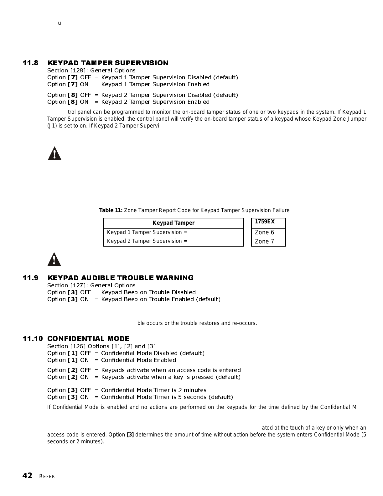
If you notice a gain or loss in control panel time, calculate the average gain or loss per day and program the opposite amount in
order to automatically correct the time setting every 24 hour s.
Example: If a control panel loses 4 minutes per month, this represents an average loss of 8 seconds per day. Therefore,
programming 008 (plus 8 seconds) into section [088] would compensate for the 8-second loss.
11.8 KEYPAD TAMPER SUPERVISION
Section [128]: General Options
Option
Option
[7]
OFF = Keypad 1 Tamper Supervision Disabled (default)
[7]
ON = Keypad 1 Tamper Supervision Enabled
Option
Option
The control panel can be programmed to monitor the on-board tamper status of one or two keypads in the system. If Keypad 1
Tamper Supervision is enabled, the control panel will verify the on-board tamper status of a keypad whose Keypad Zone Jumper
(J1) is set to on. If Keypad 2 Tamper Supervision is enabled, the control panel will verify the on-board tamper status of a keypad
whose Keypad Zone Jumper (J1) is set to off.
If a keypad tamper occurs, the control panel can transmit the appropriate Zone Tamper report code (see page 34) as originating
from the zones specified by the Table 11. If the zone (as specified by Table 11) is enabl ed, the control panel will report the tamper
as originating from the partition where the zone is assigned. If the zone is not enabled, the control panel will send the Zone
Tamper report code as ori ginating from partition 1. A Tamper/Zone Wiring Failure will al so appear in the keypads’ Trouble Display
(see page 47).
[8]
OFF = Keypad 2 Tamper Supervision Disabled (default)
[8]
ON = Keypad 2 Tamper Supervision Enabled
Regardless of whether the keypad zones are being used or not, if more than one keypad has the same Keypad
Zone Jumper setting, Keypad Ta mpe r Supervision will be lost. For example, if two of the keypads in your system
have the keypad zone jumper (J1) set to on, the control panel will not recognize a Keypad 1 Tamper Supervision
Failure.
Table 11:
When Reassign Ke ypad Zone 2 is enabled (see section 5.2), the Keypad Tamper Supervision for keypad zone 2 is
lost. Therefore, Keypad Tamper Supervision will
Zone Tamper Report Code for Keypad Tamper Supervision Failure
Keypad Tamper
Keypad 1 Tamper Supervision =
Keypad 2 Tamper Supervision =
ONLY f unction on Keypad Zone 1.
1759EX
Zone 6
Zone 7
11.9 KEYPAD AUDIBLE TROUBLE WARNING
Section [127]: General Options
Option
Option
When enabled, the keypads emit an intermittent beep tone whenever a trouble condition occurs in the system. The intermittent
beep tone remains activated until the user enters the Trouble Display by pressing the [
will re-initialize whenever a new trouble occurs or the trouble restores and re-occur s.
[3]
OFF = Keypad Beep on Trouble Disabled
[3]
ON = Keypad Beep on Trouble Enabled (default)
11.10 CONFIDENTIAL MODE
Section [126] Options [1], [2] and [3]
Option
Option
Option
Option
Option
Option
If Confidential Mode is enabled and no actions are performed on the keypads for the time defined by the Confidential Mode
Timer, all the keypads’ LEDs will be off and LCD screens will show “Paradox Family” until either a key is pressed or an access
code is entered. When the system exits Confidential Mode, the keypads will display the system’s status. Confidential Mode is
activated by enabling option [1]. Option [2] regulates whether the keypads will be acti vated at the touch of a key or only when an
access code is entered. Option [3] determines the amount of time without action before the system enters Confidential Mode (5
seconds or 2 minutes).
[1]
OFF = Con fi den tial Mod e Disab led (defa u lt)
[1]
ON = Con fi den tial Mod e Ena bl ed
[2]
OFF = Keypads ac tivate when an access code is entered
[2]
ON = Keypads activate when a key is pressed (default)
[3]
OFF = Confidential Mode Timer is 2 minutes
[3]
ON = Confidential Mode Timer is 5 seconds (default)
TBL] or [TRBL] key. The intermittent beeps
42
REFERENCE & INSTALLATION MANUAL
Page 45

11.11 INSTALLER QUICK FUNCTIONS KEYS
After entering the I nstaller Code, you can press a key to perform specific actions as descri bed below.
11.11.1 INSTALLER TEST MODE
[ENTER] + [INSTALLER CODE] + [TBL] OR [TRBL]
The Installer Test Mode allows you to perform walk tests where the bell or siren will squawk and the keypad will emit a
Confirmation Beep to indicate opened zones. To enter this mode, simply enter the Installer Code then press the [
or [
TRBL] key. The keypad will em it a c o n fir ma tio n beep. To disable this mode, press the [TBL] key again. The keypad
will emit a Rejection Beep .
11.11.2 TEST REPORT
[ENTER] + [INSTALLER CODE] + [MEM]
Sends the Test Report report code programmed in section [211] to the central station (see Reporting and Dialer
settings on pa ge32).
11.11.3 CALL WINLOAD SOFTWARE
[ENTER] + [INSTALLER CODE] + [BYP]
Refer to pa ge 45.
11.11.4 CANCEL COMMUNICATION
[ENTER] + [INSTALLER CODE] + [STAY]
Cancels all communi cation until the nex t rep ortable event.
11.11.5 ANSWER WINLOAD SOFTWARE
[ENTER] + [INSTALLER CODE] + [FORCE]
Refer to pa ge 45.
TBL]
11.12 PGM MODULES SUPERVISION
Section [129]: General Options
Option
Option
By enabling this option, the control panel will supervise the 4-PGM Output Module (APR3-PGM4) connected to the Spectra bus.
This means that whenever the module is disconnected or is not communicating with the control panel, the control panel will
attempt to transmit the Module Fault report code programmed in section [210] and the Module Loss Failure will appear in the
keypads’ Trouble Display (see page 47).
[7]
OFF = 4-PGM O u tput Module Supervision Disabled (default)
[7]
ON = 4-PGM Output Module Supervision Enabled
Modules with the APR- prefix are compa ti ble with Spectra (versions 2.0 and hig her) and Digipl ex. Modules with the APR3prefix are comp ati ble with Spectra( versions 2.0 and higher), Digi plex and DigiplexNE.
11.13 PRINTER MODULE SUPERVISION
Section [129]: General Options
Option
Option
By enabling this option, the control panel will supervise the Printer Module (APR3-PRT1) connected to the Spectra bus. This
means that whenever the Printer Module is disconnected or is not communicating with the control panel, the control panel will
attempt to transmit the Module Fault report code programmed in section [210] and the Module Loss Failure will appear in the
keypads’ Trouble Display (see page 47).
[8]
OFF = Printer Module Supervision Disabled (default)
[8]
ON = Printer Module Supervision Enabled
Modules with the APR- prefix are compa ti ble with Spectra (versions 2.0 and hig her) and Digipl ex. Modules with the APR3prefix are comp ati ble with Spectra( versions 2.0 and higher), Digi plex and DigiplexNE.
11.14 ZONE EXPANSION BUS MODULE SUPERVISION
Section [129]: General Options
Option
Option
By enabling this option, the control panel will supervise the 4- or 8-Zone Expansion Bus Module (SPC/APR3-ZX4 or SPC/APR3ZX8) connected to the Spectra bus. This means that whenever the Zone Expansion Bus Module is disconnected or is not
communicating with the control panel, the control panel will attempt to transmit the Module Fault report code programmed in
section [210] and the Module Loss Failure will appear in the keypads’ Trouble Display (see page 47).
[4]
OFF = Zone Expansion Bus Module Supervision Disabled (default)
[4]
ON = Zone Expansion Bus Module Supervision Enabled
Modules with the APR- prefix are compa ti ble with Spectra (versions 2.0 and hig her) and Digipl ex. Modules with the APR3prefix are comp ati ble with Spectra( versions 2.0 and higher), Digi plex and DigiplexNE.
S
PECTRA
1759EX
43
Page 46
11.15 WIRELESS TRANSMITTER LOW BATTERY SUPERVISION
Section [129]: General Options
Option [6] OFF = Wireless Transmitter Low Battery Super vision Disabled (def ault)
Option [6] ON = Wireless Trans mitter Low Battery Supervision Enabled
When option [6] in section [129] is enabled and the battery voltage of an Omnia wireless transmitter (motion detector or contact
switch) has dropped below recommended limits, the control panel will attempt to transmit the Wireless Transmitter Low Battery
report code programmed in section [210] and the Wireless Transmitter Low Battery Failure will appear in the keypads’ Trouble
Display (see page 47).
11.16 WIRELESS TRANSMITTER SUPERVISION OPTIONS
Section [132]: Zone Options
[7] OFF / [8] OFF: Supervision Failure Recognition Disabled (default)
When a tamper occurs on an Omnia wireless transmitter zone in a disarmed system, the cont ro l p an e l will disp l ay t h e z one as
open in the keypad display, but will not generate an alarm. When it occurs on in an armed system, the contro l panel will follo w
the zone's Alarm Types setting (see page 20). This option is not permitted on UL systems.
[7] OFF / [8] ON: Trouble Only
When a tamper occurs on an Omnia wireless transmitter zone in a disarmed system, a Wireless Transmitter Supervision Loss
will appear in the keypads’ Trouble Display (see page 47) and the control panel will attempt to transmit the TX Supervision Loss
report code programmed in section [213]. When it occurs on in an armed system, the cont ro l p an e l will follo w t h e z one's Alarm
Types setting (see page 20).
[7] ON / [8] OFF: Silen t Alarm
When a tamper occurs on an Omnia wireless transmitter zone in a disarmed system, it functions the same as the Trouble Only
setting, but it will also generate a silent alarm. A silent alarm will not trigger any bells or sirens, but the system will have to be
disarmed. I n an arm ed system, the control panel will follow the zone's Alarm Types setting (see page 20).
[7] ON / [8] ON: Audible Alarm
When a tamper occurs on an Omnia wireless transmitter zone in a disarmed system, it functions the same as the Trouble Only
setting, except it will also generate an audible alarm. In an armed system, the control panel will follow the zone's Alarm Types
setting (see page20).
11.16.1 RESTRICT ARMING ON SUPERVISION LOSS
Section [131]: Arming/Disarming Options
Option
Option
The control panel will not allow users to arm the system if it receives a Supervision Loss signal. Please note that the
Wire less Transm itter S upervi sion Op tions (see section 11. 16) must be enabled. The control panel will not arm any
partition until all Supervisi on Loss trouble conditions are rectified .
[6]
OFF = Disabled (defa ult)
[6]
ON = Restrict Arming on Wireless Transmitter Supervision Loss
11.16.2 SUPERVISION BYPASS OPTIONS
Section [131]: Arming/Disarming Options
Option
Option
When this feature is enabled, the Wireless Transmitter Supervision Options will follow th e zone's bypass de finition.
This means the control panel will not perform any action if a Supervision Loss occurs on a bypassed zone. When this
feature is disabled, the Wireless Transmitter Supervision Options will ignore the bypass definition. This means the
control panel will generate an incident as per Wireless Transmitter Supervision Options if a supervision loss occurs on
a bypassed zone.
[7]
OFF = Generate Supervision Loss if detected on a Bypassed Wireless Transmitter Zone
(default)
[7]
ON = No Supervision Loss if Detected on a Bypassed Wireless Transmitter Zone
11.17 REPROGRAM ALL EXPANSION MODULES
Section [750]
After removing an expansion bus module from the communication bus, the control panel keeps the module’s programmed
sections in memory. Therefore, if you add or replace a module or when you have downloaded the contents of the Paradox
Memory Key (see section 3.4), you can reprogram the modules with the settings saved in the control panel. To do so, enter
section [750] and press [
ENTER]. The keypad will emit 2 beeps every second while downloading.
44
REFERENCE & INSTALLATION MANUAL
Page 47

PART 12: SETTINGS FOR WINLOAD SOFTWARE
12.1 PA NEL ANSWER OPTI ONS
The following two opti ons defi ne how the control pane l answers an incoming cal l from a compu ter usi ng the WinLoad Sof tware for
Windows®.
12.1.1 ANSWERING MACHINE OVERRIDE
Section [077]
000 = Disabled, 010 to 255 seconds, Default = disabled
When using the WinLoad software to communicate remotely with an installation site that uses an answering machine
or service, the answering machine override must be programmed. Using the WinLoad software you wil l call the control
panel, hang up, then call back. If the installation site is called back within the programmed delay period, the control
panel will override the answering machine or service by picking-up the line after the first ring on the second call. You
must wait at least 10 seconds before attempting the second call, otherwise, the control panel will think it is the same
call. For detai ls on how to use the WinLoad software, r efer to the WinLoad Help Manual.
Example: A secu rity installation is using a n answe ring machine set to answ er after three ring s. If section
[077] has been programmed with 040 (40 seconds ) and the second call is made within 40 seconds, the
control panel will pick up the line on the first ring. If it takes more than 40 seconds, the control panel will not
answer on the first ring and the answering machine will answer after three rings.
12.1.2 N
UMBER OF RINGS
Section [078]
000 = disabled, 001 to 015 rings, Default = 8 rings
This value represents the number of rings the control panel will wait before picking-up the line. If the line is not
answered after the number of programmed rings, the control panel will answer the call. You must wait at least 10
seconds before attempting the second cal l or the control pane l will think it is the same call.
12.2 PA NEL IDENTIFIER
Section [141]
0000 to FFFF
This 4-digit code identifies the contro l panel to the WinLoad software before init iat ing communicati on. The control panel will verify
that the Panel Identifier in the WinLoad software is the same. If the codes do not match, the control panel will not establish
communication. Therefore, be sure to program the same panel identifier into both the Spectra control panel and the WinLoad
software.
12.3 PC PASSWORD
Section [142]
0000 to FFFF
This 4-digit password identifies the PC to the panel before establishing communication. Program the same PC Password into
both the Spectra control panel and the WinLoad sof twar e. If the passwords do not match, the WinLoad soft ware will not establish
communication.
12.4
PC TELEPHONE NUMBER
Section [150]
Up to 32 digits
The control panel will dial this number when trying to initiate communication with a computer using the WinLoad software. You
can enter any digit fro m 0 to 9 and any special keys or functi ons (see Table 9 on page 35) up to a maximum of 32 digits.
12.5 CA LL WINLOAD SOFTWARE
[ENTER] + [INSTALLER CODE] + [BYP]
The control panel will dial the PC Telephone Number programmed in section [150] in order to communicate with the WinLoad
software. The control panel and the WinLoad software will verify that the Panel Identifier and the PC Password match before
establishing communication.
12.6 ANS WER WINLOAD SOFTWARE
[ENTER] + [INSTALLER CODE] + [FORCE]
In order to perform on-site upload/download connect your computer directly to the control panel using an ADP-1 line adapter. In
the WinLoad software set Dialing Method to Blind Dial. Program the panel telephone number in WinLoad software and follow the
S
PECTRA
1759EX
45
Page 48

instructions on the ADP-1 adapter. When the computer has dialed, press [ENTER] followed by the Installer Code, then press the
[
FORCE] key to manual ly answer the WinLoad softwar e fr om the control panel.
12.7 AUTO EVENT BUFFER TRANSMISSION
Section [136]: Dialer Options
Option
Option
When the event buffer reaches 50% capacity, the control panel will make two attempts to establish communication with a PC
using the WinLoad software by calling the PC Telephone Number programmed in section [150]. The WinLoad software must be
in Wait to Dial mode. When the system establishes communication, it will upload the contents of the event buffer to the WinLoad
software. If communication is interrupted before completing transmission or if after two attempts communication is not
establi shed, the sys tem will wait until the Event Buffer attains another 50% capacit y before attempting to re-communicate wit h the
central station. When the Event Buff er is full, each subsequent new event will erase the oldest event in the buffer.
[2]
OFF = Auto Event Buffer Transmission Disabled (default)
[2]
ON = Auto Event Buffer Transmission Enabled
12.8 CALL BACK WINLOAD
Section [136]: Dialer Options
Option
Option
For additional security, when a PC using the WinLoad softwa re attempts to comm unicate with the c ontrol panel, t he control panel
can hang up and call the PC back in order to re-verify identification codes and re-establish communication. When the control
panel hangs up, the WinLoad software automatically goes into Wait for Call mode, ready to answer when the control panel calls
back. Please note that the PC Telephone Number must be programmed in section [150] i n order to use the Call Back feature .
[1]
OFF = Call Bac k WinLo ad Disa ble d (defa ul t)
[1]
ON = Call Bac k WinLo ad En ab led
46
REFERENCE & INSTALLATION MANUAL
Page 49

PART 13: USER OPERATION
13.1 TROUBLE DISPL AY
The Spectra system cont inuousl y monitor s fourt een possi ble tro uble condi tions . When a troubl e condit ion occur s, the [TBL] key or
[
TRBL] indicator wil l illuminate on the LED keypads or “Trouble” will appear on the LCD ke ypad’s screen. Press the [TBL] or [TRBL]
key to switch to the Tr ouble Display. The [
condition will illuminate on the LED keypads (see Table 12) or the appropriate trouble message will appear on the LCD keypad.
Press the [
CLEAR] key to exit the Trouble Display.
TBL] key or [TRBL] indicator will flash and lights corresponding to an existing trouble
Please note t hat the keypad can b e programmed to emit a
Pressing the [
LED # Description Details
[1]
[2]
[3]
[4]
[5]
[6]
[7]
[8]
[9]
[10]
[
STAY] or
[11]
TBL] or [TRBL] key will stop the beeping.
No/Low Battery Failur e The control panel performs a dynamic bat ter y test under load every 60 seconds.
This trouble indi cates that the back up batt e ry is disconnected or that the battery
should be repl aced, as it will not provide a dequate current in case of AC loss. This
trouble will also appe ar when th e control pa nel is running on batt ery power and the
battery voltage has dropped to 10.5 volts or lower. This means the battery m ust be
recharged or replaced.
Wireless Transmitter
Low Battery
Power Failure Upon power failure, the AC LED on all keypads will turn off. The control panel can
Bell Disconnected This trouble occurs when a bell or siren is not connected to the bell output
Maximum Bell Curr ent The
Maximum Auxiliary Current The auxiliary outp ut uses a fuseless circuit to protect the power sup ply against
Communicator Report Fail The control panel has failed all attempts to communicate with the central
Timer Loss The contro l panel ’s in ternal clock mus t be re-pro grammed. To re-program the timer
T am per/Z one Wiring Fail If the T amper Re cogni tio n optio ns are enab le d (see p age 30), this trouble i ndica tes
Telephone Line Monitoring If the Telephone Line Monitori ng (TLM) feature is enabl ed (see section [135]), thi s
Fire Loop Trouble Indicates a wiri ng problem on a Fir e Zone. Press [
The battery voltage of an Omnia wireless transmitter has dropped below
recommended lim it s. To determine the zones generating the tr ouble, examine the
Low Battery LED indicators on all the transmitters. The batteries should be
replaced.
transmit the report code programmed in section [205]. This report code can be
delayed by programmi ng a Power Failure Report Delay in section [086]. The AC
LED turns back on as soon as power is restored.
terminals. If you are not using the
the bell output.
BELL output uses a fuseless circuit and will automatically shut down if the
current excee ds 3A. Afte r openin g the short or reduci ng the load, the be ll cur rent i s
restored upon the following alarm generation. This trouble indicator will only
appear when a conditi on has occurred that would activate the bell outpu t (e. g.
during an alarm) .
current overload and automatically shuts down if the cur rent exceeds 1.1A. After
opening the short or reducin g the load, the panel will restore power to the auxiliary
output.
monitoring st ation.
press the [8] key followed by the current time using the 24-hour clock (i.e. 8: 30PM
= 20:30).
a wiring prob lem on one or more zones or t hat th e cove r has been r emove d on one
or more wireless tran sm itters. To provide line short recognit ion the zone
connections must have EOL resistors. If you press the [9] key , the keypad will
display which zones are in trouble. Enter the Installer Code to clear Tamper
troubles.
trouble indicates that the control panel has not detected the presence of a
telephone line for 30 seconds.
generating th is trouble.
BEEP every 5 seconds whenever a new tr ouble condi tion has occurred .
T able 12:
Trouble List
BELL terminals, connect a 1KΩ resistor across
STAY] to view the zones that are
S
PECTRA
1759EX
47
Page 50

LED # Description Details
FORCE]
[
or [16]
Keypad Fault If the keypad is no longer communic ating with the con trol pane l, the [
will flash, the [
and the keypad will emit four consecutive beeps at 5-second intervals. Press any
key on the keypad to term inate t he “beepi ng” seque nce. When communi cati on has
been restored, the system will revert to previous status.
[
BYP]
or [12]
[MEM]
or [13]
Module Loss
Wireless Transmitter
Supervision Loss
A bus module is no longer communicating with the control panel. The
module’s supervision option must be enabled [129].
One or more wireless transmitters are no longer communicating with the receiver.
If you press the [
13.2 PROGRAMMING ACCESS CODES
Access Codes are personal identification numbers that allow you to enter certain programming modes, arm or disarm your
system as well as activate or deactivate PGMs. The Spectra security system supports the following:
System Master Code arms or disarm partitions using any arming method and can create, modify or delete any User Access
Code. Only the System M aster Code can modify or delete User Access Codes assigned to both partitions.
Master Code 1 is permanently assigned to partition 1 and can be used to create, modify or delete User Access Codes that are
assigned to partition 1.
Master Code 2 is permanently assigned to partition 2 (except when partitioning is disabled, Master Code 2 will be assigned to
partit ion 1) and can be used to create, modify or delete User Access Codes that are assigned to the same partit ion.
45 User Access Codes (including 1 Duress code)
Table 12:
Tr ouble List
FORCE] key will illuminate (the LCD keypad displays “Keypad Fa ult”)
MEM] key, the keypad will display which zones are in trouble.
TBL] or [TRBL]
How Do I Prog ra m A ccess Codes?
1) Press [ENTER].
2) Key in the [
3) Key in 3-digit [
4) Key in new 4- or 6-digit [
[
ENTER] flashes. Return to step 3.
SYSTEM MASTER CODE] or [MASTER CODE].
SECTION] (see Table below).
ACCESS CODE].
How Do I Delete Access Code s?
1) Repeat steps 1 to 3 (see above).
2) Press the [
FORCE] key once for each digit in the access code (4 or 6 times) until the keypad emits a Confirmation Beep.
Section User Codes
[001]
[002]
[003]
[004] to [047]
[048]
User Code 001 = System Master Code
User Code 002 = Master Code 1
User Code 003 = Master Code 2
User Code 004 to User Code 047
User Code 048 or Duress Code
13.3 DISARMING & DEACTIVATING AN ALARM
To disarm an already armed system or to deactivate an al arm, simply key in a val id access code. Program a designated entry/exit
point, such as the front door or the garage door with an Entry Delay Tim er. When these entry/exit point are opened (breached), it
will set off a timer. The system will not generate an alarm until this timer elapses, giving users enough time to enter the premises
and disarm the system. Any user can disarm the system, except users have been assigned the Arm Only Option.
How Do I Disarm the Syst em or Deactivate an Alarm?
1) Key in your [ACCESS CODE]*.
The arm or alarm indic at ion will t urn off and the keypad will emit a Confirmation Beep.
*IF YOU HAVE ACCESS TO BOTH PARTITIONS
Press the key corres ponding to the partition you wish to Disarm or to Disarm both partitions, press the [1] key then after the
Confirmation Beep press the [2] key.
13.4 RE GULA R ARM IN G
This method, commonly used for day-to-day arming, will arm all the zones in the selected partition. If you make a mistake, the
48
REFERENCE & INSTALLATION MANUAL
:
Page 51

keypad will emit a Rej ection Beep. When you h ave correctly armed the system, the appropri ate ARM indication will turn on and the
Exit Delay will be initiated. Please note that Regular Arming can also be activated through Auto-Arming, Keyswitch Arming or
One-Touch Arming.
How Do I Regular Arm?
1) Green “READY” indicator must be illumin ated. Unless the syst em is partitioned, in which case all zones in the desired partition must be closed.
2) Key in a valid [
*IF YOU HA VE ACCESS TO BOT H PARTITIONS
Press the key corresponding to the partition you wish to arm. To arm both partitions, press the [1] key then after the
Confirmation Beep press the [2] key.
ACCESS CODE]*.
13.5 STAY ARMING
This method allows users to remain in the protected area while partially arming the system. For example, when going to sleep at
night, entry/exit points like doors and windows can be armed while other zones like motion detectors remain deactivated. Please
note that Fire Zones cannot be bypassed.
How Do I Stay Arm?
1) All zones in the desired partition (except Stay Zones) must be closed.
2) Press the [
3) Key in a valid [
*IF YOU HA VE ACCESS TO BOT H PARTITIONS
Press the key corresponding to the partition you wish to Stay Arm. To Stay Arm both partitions, press the [1] key then after the
Confirmation Beep press the [2] key.
If you make a mistake, the keypad will emit a Rejection Beep. When you have correctly Stay Armed the system, the appropriate
ARM or STAY indication appears and the Exit Delay is initiated. Stay Arming can also be activated using Auto-Arming, Keyswitch
Arming or One-Touch Arming. The User Code must have the Stay Arming Option enabled.
STAY] key.
ACCESS CODE]*.
:
:
13.6 IN STANT ARMING
After Stay Arming the system and during its Exit De lay, press and hold the [STAY] key for 3 seconds. You should hear a
Confirmation Beep. Thi s wil l switch all armed zones to Instant zones.
If you have access to both partitions:
To Instant Arm one partition, press [
To Instant Arm both partitions, press [
13.7 FORCE ARMING
Force Arming allows users to rapidly arm the system, without having to wait for all zones in the system to be closed. Force
Arming is commonly used when a motion detector is protecting the area occupied by a keypad. Therefore, when arming the
system, if the motion detector is set as a Force Zone, the control panel will ignore the zone and allow users to arm the system
even if the zone is open. Any open Force Zones at the time of arming will be considered deactivated by the control panel. If
during this period a deactivated zone is closed, the control panel will revert that zone to active status, hence, will generate an
alarm if breached.
How Do I Force Arm?
1) All zones in the desired partition (except For ce Zones) must be closed.
2) Press the [
3) Key in a valid [
*IF YOU HA VE ACCESS TO BOT H PARTITIONS
Press the key corresponding to the partition you wish to Force Arm. To arm both partitions , press the [1] key then after the
Confirmation Beep press the [2] key.
If you make a mistake, the keypad will emit a Rejection Beep. When correctly Force Armed, the appropriate arm indication
appears and the Exit Delay will initiate. Please note that Force Arming can also be activated using One-Touch Force Arming.
Also, note that the User Access Code m ust have the Force Arming Option enabled.
FORCE] key.
(NOT TO BE USED WITH UL INSTALLATIONS)
ACCESS CODE]*.
STAY] + [ACCESS CODE] + Select Partit ion + [CLEAR] + press & hold [STAY]
STAY] + [ACCESS CODE] + [1] + [2] + press & hold [STAY]
:
13.8 MANUAL B Y PASS PROGRAMMING
Manual Bypass Programming allows users to program the alarm system to ignore (deactivate) specified zones the next time the
system is armed. The Access Code must have the Bypass Programming Option enabled. Please note that Fire Zones cannot be
bypassed. Manual Bypass Programming can also be activated using One-Touch Bypass Programming.
S
PECTRA
1759EX
49
Page 52

How do I Program Bypass Entries?
1) Press the [BYP] key.
2) Key in a valid [
3) Select one or more [
ACCESS CODE]*.
ZONES] you wish to bypass.
4) Once you have entered the desired bypass entries, press the [
ENTER] key to accept these entries.
*IF YOU HAVE ACCESS TO BOTH PARTITIONS
Press the key corres ponding to the desired partition.
13.8.1 BYPASS RECALL FEATURE
After disarming the system, the control panel will erase the bypass entries. By using the Bypass Recall Feature, you
can reinstate the previous bypass entries saved in memory. This eliminates the need to manually program the bypass
entries every t ime you arm the system. The Access Code must have the Bypass Programming O pti on enabled.
How Do I Recall Byp ass Entries ?
1) Press the [BYP] key.
2) Key in your [
3) Press the [
4) Press the [
ACCESS CODE]*.
BYP] key. Previously byp assed zones will illuminate.
ENTER] key.
*IF YOU HAVE ACCESS TO BOTH PARTITIONS
Press the key corres ponding to the desired par tition.
13.9 ONE-TOUCH ARMING
One-Touch Arming allows users to arm the system without using an access code. Simply press and hold a key. One-Touch
Arming can be used to allow specific individuals like service personnel (i.e. cleaners, maintenance) to arm the system when
leaving the protected area, without giving them access to any other alarm system operations.
One-Touch Regular Arming
Press and hold the [
One-Touch Force Arming
Press and hold the [
One-Touch Bypass Programming
Press and hold the [
ENTER] key for 3 seconds* to arm al l zones in the partition.
FORCE] key for 3 seconds* to bypass any open Force Zones.
BYP] key for 3 seconds* to access Bypass Pro gramm ing Mode.
:
:
One-Touch Stay Arming
Press and hold the [
STAY] key for 3 seconds* to arm all zones not defined as Stay Zones.
Fast Exit - When the system is already Stay Armed:
• To Exit and Stay Arm: Press and hold the
period, the system will return to Stay Arming.
• To Exit and Regular Arm: Press and hold the
Delay period, the control pan el wil l swit ch to Regul ar Armin g.
• To Exit and Force Arm: Press and hold the
Delay period, the control pan el wil l swit ch to Forc e Arming.
* If you have access to both part itions af te r activa ting a one-touch f eature, press the key corres ponding to the desir ed pa rtiti on.
To select both partitions, press the [1] key then after the confirmati on beep press the [2] key.
13.10 KEYSWIT CH ARM IN G
A keyswitch can be used to a rm and disarm the system. Assign the keyswitch to a specific partition and program t he keyswitch to
Stay or Regular Arm the assigned partition. Also program the keyswitch to function as a Maintained or Momentary keyswitch. To
arm the system using a Maintained Keyswitch, set the keyswitch to the
OFF position. To arm the system using a Momentary Keyswitch, set the keyswitch to the ON position then turn it back to the OFF
position. Repeating this sequence will disarm the system.
13.11 PANIC ALARMS
In case of eme rgency, the Spectra system provides up to three panic alarms. These panic alarms, if programmed, will immediately
generate an alarm after pressing and holding two specific keys for two seconds, as described below.
Press and hold keys [1] and [3] for a panic alarm.
Press and hold keys [4] and [6] for a panic or medical ala rm.
Press and hold keys [7] and [9] for a panic or fir e alarm.
[STAY]
key for 3 seconds*. The system will switch to Exit Delay. At the end of the Exit Delay
[
ENTER
]
key for 3 seconds*. The system will switch to Exit Delay. At the end of the Exit
[FORCE]
key for 3 seconds*. The system will switch to Exit Delay. At the end of the Exit
ON position. To disarm t he system set the keyswitch to the
50
REFERENCE & INSTALLATION MANUAL
Page 53

13.12 AUTO-AR MING
(NOT TO BE USED WITH UL INSTALLATIONS)
Each partit ion can be pr ogrammed to arm every day at the time speci fied by the Auto-Arm Timer or for the period specified by the
No Movement Timer. The user can program the Auto-Arm Timer by using the System Master Code, Master Code 1 or Master
Code 2. Please note that the cont rol panel will enter a 60-second Exit Delay period before arming the system. At this point, Auto-
Arming can be cancelle d by entering a valid access cod e.
13.13 ALARM MEMORY DISPLAY
A record of all alarm situa tions that occur wi ll be stor ed in memory. After disarming the syst em, pressi ng the [MEM] key will display
which zones were in alarm during the alarm period. To exit the Alarm Memory Display, press the [
will erase the contents of the alarm memory ever y time the system is armed.
13.14 PR OG RAMMING CHIME ZONES
Users can program which zones will be Chim e Enabled. A Chime Enabled zone will cause the keypad to emit a rapid i ntermittent
beep tone (
separately.
10-Z
ONE LED KEYPAD:
Press and hold any key f rom [1] to [10] for 3 seconds t o activate o r deactivate Chiming for zones 1 to 10. For example, press and
hold the [1] key to enable chiming on zone 1. If after pressing and holding a key, the keypad emits a confirmation beep, this
means the chime feature has been enabled for that zone. If the keypad emits a rejec ti on beep, this means the chime feature has
been disabled for the corresponding zone.
16-Z
ONE LED KEYPAD:
Press and hold the [9] key. Enter the 2-digit (01 to 15) zone number(s). When the corresponding LED is on, the zone is chimed.
When the corresponding LED is off, the zone is unchimed. When the desired zones are chimed, press [
LCD K
Press and hold the [9] key. Enter the 2-digit (01 to 16) zone number(s), or use the arrow keys to scroll through the zones. and
when the appropriate zone is displayed, pres s the [
BEEP-BEEP-BEEP-BEEP) advising the user every time it is opened. Each keypad must be Chime Programmed
EYPAD:
CLEAR] key. The control panel
ENTER].
FNC1] key. When the desired zones are chimed, press [ENTER].
13.15 KEYPAD MUTING
(NOT TO BE USED WITH UL INSTALLATIONS)
Press and hold the [CLEAR] key for 3 seconds to enable or disable keypad muting. When muted, the keypad will only beep when
a key is pressed or when the keypad em its a Rejection or Confirmation Beep. All other beep functions are disabled.
13.16 KEYPAD BACKLIGHT (1686H and 1686V Only)
The illumination level behind the keys can be modified to suit the user’s needs. There are four backlight levels. The [MEM] key is
used to set the desired level. Each consecutive push of the [
reached. After reaching the maximum level, the backlight level will return to the lowest level and the whole process is repeated.
To change the backlight level:
How do I Modify Th e Backlight?
1) Press and hold the [MEM] key for 3 seconds.
2) The [
3) Press the [
4) Press [
MEM] key will illuminate.
MEM] key to set the desired backlight level.
CLEAR] or [ENTER] to exit.
MEM] key will i nc r ease the ba c k ligh t level un ti l th e m aximum lev e l is
S
PECTRA
1759EX
51
Page 54

FCC WARNINGS
IMPORTANT INFORMATION
This equipment complies with Part 68 of the FCC rules subpart D and CS-
03. Insi de the cover of th is equipment is a label th at co nt a in s, a mong ot he r
information, the FCC registration number of this equipment.
NOTIFICATION TO TELEPHONE COMPANY
Upon re qu es t, c us t o me r shall not if y te lephone c ompany of par t ic ular line to
which the connection will be made, and provide the FCC registration
number and the ringer equivalence of the protective circuit.
FCC REGISTRA TION NUMBER:5A7CAN-22633 - AL - E
RINGER EQUIVALENCE NUMBER:0.1B (U.S. & CANADA)
USOC JACK: RJ31X (USA), CA31A (CANADA)
TELEPHONE CONNECTION REQUIREMENTS
Except for telephone company provided ringers, all connections to the
telephone network shall be made through standard plugs and telephone
company provided jacks, or equivalent, in such a manner as to allow for
easy, immediate disconnection of terminal equipment. Standard jacks shall
be so arranged that, if plug connected thereto is withdrawn, no interference
to operation of equipment at customer's premises which remains connected
to telephone network shall occur by reason of such withdrawal.
INCIDENCE OF HARM
Should terminal equipment/protective circuitry cause harm to telephone
network, telephone company shall, where practicable, notify customer that
temporary disconnection of service may be required; however, where prior
notice is not practicable, the telephone company may temporarily
discontinue service if action is deemed reasonable in circumstances. In
case o f temporary discontinuance, telephone company shall promptly notify
custom e r and wil l be gi ven oppo rtunity to co r rect the sit uation.
CHANGES IN TELEPHONE COMPANY EQUIPMENT OR
FACILITIES
The tele phone company may m ak e c hanges in its com mu ni ca tion fac il iti es ,
equipm ent operatio ns or proce dures, wher e such actio ns are reas onably
required and proper in its business. Should any such changes render
custom er's termina l equipm ent incompa tible with t he telephon e company
facilities, the customer shall be given adequate notice to effect the
modifications to maintain uninterrupted service.
radio frequency energy, and, if not installed and used in accordance with
the inst ructi ons, may cause ha rmful interfe rence to r adio co mmuni cations .
However, there is no guarantee that interference will not occur in a
particular installation. If this equipment does cause harmful interference to
equipment intermittently, the user is encouraged to try to correct the
interference by one or more of the following measures: (1) re orient or
relocate the receiving antenna; (2) increase the separation between the
equipment and receiver; (3) connect the equipment to an outlet on a circuit
other than the one to which the receiver is connected, or (4) consult the
dealer or an experienced radio/tv technician for assistance.
CAUTION:
Changes or modifications not expressly approved by PARADOX
SECURITY SYSTEMS could void the user's authority to operate the
equipment.
WARRANTY
The Sell er warrant s its products to be free from de fects in mater ials and
workmanship under normal use for a period of one year (except as
indicated ot herwise). Except as spec ifically stat ed herein, all express or
implied warranties whatsoever, statutory or otherwise, including without
limitation, any implied warranty of merchantability and fitness for a
particular purpose, are expressly excluded. Because Seller does not install
or connect the products and because the products may be used in
conjunction with products not manufactured by Seller. Seller cannot
guaran tee the perfo rmance of the security sys tem. Seller o bligation and
liabil ity u nder t hi s war ranty is e xpr essly lim ite d to re pair ing o r re plac ing, at
Seller's opt ion, any product not meeting the speci fications. In no event shall
the Seller be liable to the buyer or any other person for any loss or
damag es whether di r ec t or indire ct or cons eq ue nt ial or inci de nt a l, in cluding
without limitation, any damages for lost profits stolen goods, or claims by
any o ther party, cau sed by def ective goods or otherwis e arising from th e
improper, incorrect or otherwise faulty installation or use of the
merchandise sold.
A TTACHMENT LIMITATION NOTICE
The Industry Canada label identifies certified equipment. This certification
means that the equipment meets certain telecommunications network
protective, operational and safety requirements. The Department does not
guarantee the equipment will operate to the user 's satisfaction.
GENERAL
This eq uipment shall not be use d on coin telephon e lines. Connect ion to
party line se r v ic e is sub j ec t to state tariffs .
RINGER EQUIVALENCE NUMBER (REN)
The ren is useful to determine the quantity of devices that you may connect
to your telephone line and still have all of those devices ring when your
telephone number is called. In most, but not all areas, sum of the ren's of
all devices connected to one line should not exceed five (5. 0). To be certain
of the num ber of dev ices th at you may c onne ct to your li ne , you m ay w ant
to contact your local telephone company.
EQUIPMENT MAINTENANCE FACILITY
If you experience trouble with this telephone equipment, please contact
facilit y indi cate d be lo w for i nf orma tion on o btain ing s ervi ce o r repairs . Th e
telephone company may ask that you disconnect this equipment from
network until problem is corrected or until you are sure that the equipment
is not malfunctioning.
FCC P ART 15, WARNINGS INFORMATION TO USER
This eq uipment has bee n tested and fo und to comply with the li mits for
Class B digital devices, pursuant to Part 15 of FCC rules. These limits are
designed to provide reasonable protection against harmful interference in a
residential installation. This equipment generates, uses and can radiate
52
REFERENCE & INSTALLATION MANUAL
Before installing this equipment, users should ensure that it is permissible
to be connected to the facilities of the local telecommunications company.
The equipment must also be installed using an acceptable method of
connection. The customer should be aware that compliance with the above
conditions may not prevent degradation of service in some situations.
Repair s to cert ifie d equi pmen t sh ould be made by an auth ori zed Can ad ian
maintenance facility designated by the supplier. Any repairs or alterations
made by t he user to this equip ment, or equipm ent mal funct ions, m ay give
the telecommunications company cause to request the user to disconnect
the equi pm en t.
Users should ensure for their own protection that the electrical ground
conne ctio ns of th e pow er utili ty, teleph one l ines and in ter nal me tallic wat er
pipe system, if present, are connected together. This precaution may be
particu larly important in rural are as .
CAUTION: Users should not attempt to make such connections
themselves, but should contact the appropriate electrical inspection
authority, or electrician, as appropriate.
The Load Number (LN) assigned to each terminal device denotes the
percentage of the total load to be connected to a telephone loop which is
used by the device, to prevent overloading. The termination on a loop may
Page 55

consist of any combination of devices subject only to the requirement that
the total of the Load Numbers of all of the devices does not excee d 100.
Industry Canada certification is only applicable to installation of devices
which include transformers approved by the Canadian Standards
Association (CSA).
RESTRICTIONS CONCERNANT LE RACCORDEMENT DE
MATÉRIEL
L'étiquette d'Industrie Canada identifie le matériel homologué. Cette
étiquette certifie que le matériel est conforme à certaines normes de
protection, d'exploitation et de sécurité des réseaux de
télécommunications. Le Ministère garantir toutefois pas que le matériel
fonctionnera à la satisfaction de l'utilisateur.
Avant d' in st a lle r c e m at ériel, l' uti li sateur d oi t s 'assure r q u'i l est pe rm is de le
raccorder aux installations de l'entreprise locale de télécommunication. De
plus, le matériel doit être installé en suivant une méthode acceptable de
raccordement. L'abonné ne doit pas oublier qu'il est possible que la
conformité aux conditions énoncées ci-dessus n'empêchent pas la
dégradation du service dans certaines situations.
Les réparations de matériel homologué doivent être effectuées par un
centre de s erv ice d'en tre tien ca nadi en au tor isé dési gné pa r l e fou rni sse ur.
La compagnie de télécommunications peut demander à l'utilisateur de
débrancher un appareil à la suite de réparations ou de modifications
effectuées par l'utilisateur ou à ca use d'un mauvais fonctionnement.
Pour sa propre prot ection, l'utilisate ur doit s'assu rer que tous les fils de
mise à l a t erre de l a sou rce d 'ene rgi e éle ctr ique , des lign es té léph on ique s
et des canal is at ion s d' ea u mét al li ques , s' i l y en a, sont rac cor dés ense mb le.
Cette précaution est particulièrement importante dans les régions rurales.
AVERTISSEMENT: L'utilisateur ne doit pas tenter de faire ces
racco rdements lui-mê me; il doit av oir recours à un e service d'ins pection
des installations électriques, ou à un électricien, selon le cas.
L'indice de charge (IC) assigné à chaque dispositif indique, pour éviter
toute surcharge, le pourcentage de la charge totale qui peut être raccordée
à un c ircui t té léph oniq ue bo uclé util isé pa r c e dis pos itif. La t ermin ai son du
circuit bouclé peut être constituée de n'importe quelle combinaison de
dispositifs, pourvu que la somme des indices de charge de l'ensemble des
disposi tifs ne dépasse pas 100.
UL AND ULC WARNI NGS
UL AND C-UL INSTAL LATION NOTES
This equipment is UL listed in accordance with standard UL1023
(Household Burglar -- A larm Systems Units), standard UL 985 (Household
Fire Warning Units) and standard UL1635 (Digital Alarm Communicator
System Units). This equipment has the capability of being programmed with
features not verified for use in UL installations. To stay within these
standards, the installer should use the following guidelines when
configuring the system:
• All components of the system should be UL listed for the intended
application.
• If the system will be used for “Fire” detection, the installer should refer
to NFPA Standards #72, Chapter 2. In ad dition, once installation is
complete, the local fire authority must be notified of the installation.
• This equipment must be verified by a qualified technician once every
three ye ar s.
• All keypads must us e a tamper switch.
• Maximum allowed entry delay is 45 seconds.
• Maximum al lowed exi t delay is 60 seconds.
• Mini mu m 4 minute s for bell cut-o ff tim e.
• The following features do not comply with UL requirements: Bypass
Recall and Aut o Trouble Shut down.
• Do not conn ect the pr imary indicating device to a relay. The inst aller
must use the bell output.
• To comply with UL985, the auxiliary power output should not exceed
200mA. Please refer to Table 2: Current Consumption Table on
page 8.
RECOMMENDED:
• EOL resistor part #2011002000
• For UL Installations: Basler Electric BE156240CAA007 16.5VAC
min. 40VA
• 12vdc 4Ah rechargeable acid/lead or gel cell backup battery (YUASA
model #NP7-12 recommended) for residential use. Use a 7Ah battery
to comply with fire requirements.
• Wheelock 46T-12 siren
All outputs are Class 2 or power-limited, except for the battery
terminal.The Class 2 and power-limited fire alarm circuits shall be
installed using CL3, CL3R, CL3P, or substitute cable permitted by
the National Electrical Code, ANSI/NFPA 70.
La certi fication d'Ind ustrie Canada s'applique se ulement aux ins tallati ons
d'appareils utilisant un transformateur approuvé par l'Association
Canadienne de Normalisation (CSA).
For technical support in the US and Canada, call 1-800-791-1919,
Monday to Friday, 8 a.m. to 8 p.m. EST.
Technical support can al so be reached by fax at (450) 491-2313, or
via e-mail at support@paradox.ca.
© 2002 Paradox Security Systems Ltd.
Spectra, WinLoad, InTouch, ParaVox, Digital Vision and Digigard
are trademarks of Paradox Security Systems Ltd.
S
PECTRA SERIES
53
Page 56

INDEX
Numerics
24Hr. Buzzer Zone ..........................................................19
24Hr. Delayed Fire Zone
24Hr. Standard Fire Zone
.................................................19
................................................19
A
AC Power ..........................................................................6
Access Code Length
Access Code Programming
Access Codes
Account Numbers
Ademco Contact ID
Ademco Contact ID Options
Ademco Express
Adjust Clock
Alarm Memory Display
Alarm Options
Alarm Relay
Alarm Relay Options
Alarm Report Code Transmission, Delay
Alarm Types
Alternate Dial Option
Answer Upload/Download Software
Answer WinLoad Software
Answering Machine Override
Arming and Disarming Options
Arming Report Codes
Auto Event Buffer Transmission
Auto Force Arming
Auto Test Report
Auto-Arming On No Movement
Auto-Arming On Time
Auto-Arming Options
Auxiliary Power
....................................................................41
.......................................................................8
....................................................................20
....................................................... 1 4
.............................................48
.................................................................14
............................................................35
.........................................................36
............................................36
.............................................................36
....................................................51
..................................................................29
....................................................... 4 0
........................21
....................................................... 3 8
................................43
..............................................45
..........................................45
.......................................27
......................................................33
......................................46
..........................................................27
.............................................................38
.......................................28
......................................................27
.......................................................28
..................................................................8
B
Backlight, Keypad ............................................................5 1
Backup Batte r y
Battery Charge Current
Battery, Backup
Beep On Exit Delay
Beep On Trouble
Bell Cut-Off Timer
Bell on Communication Failure
Bell Output Connection
Bell Squawk On Arm/Disarm With Keypad
Bell Squawk On Arm/disarm with Remote Control
Burglary Zones, 24 Hr.
Buzzer Zone
Bypa ss Opt ions, Su pervisio n
Bypass Programming
Bypass Recall Feature
Bypass Zones
..................................................................6
...................................................41
.................................................................6
......................................................... 2 8
.............................................................42
............................................................29
.......................................37
.....................................................8
......................29
..........29
....................................................19
....................................................................19
..........................................44
......................................................49
....................................................50
..................................................................20
C
Call Back Feature ............................................................46
Call Upload/Download Software
Call WinLoad Software
Cancel Communication
Central Station Telephone Numbers
Charge Current
Chime Zones
Clock Adjust
Configuring The LED Keypads
Connecting
Bells or Sirens ...............................................................8
Fire Zones ..................................................................10
Keypad Zones ...............................................................9
Keypads .......................................................................9
Keyswitches ................................................................10
PGMs ........................................................................... 8
Single Zone Inputs .........................................................9
Telephone Lines ............................................................ 8
Contact ID Options
Current Consumption Table
................................................................41
...................................................................51
....................................................................41
....................................................45
...................................................43
..........................................................36
......................................43
...............................35
........................................12
..............................................8
D
Data Display Mode ..........................................................11
Delay Before Alarm Report Code Transmission
Delay Between Dialing Attempts
Delay Power Failure Report
Delay, Pager Report
Delayed Fire Zone
Dial Tone Delay
Dialer settings
Dialing Attempts
Dialing Method
Disarm Reporting Options
Disarming
Duress Code
........................................................................48
...................................................................15
........................................................36
...........................................................19
...............................................................37
..................................................................32
.............................................................. 37
................................................................37
.....................................38
............................................38
...............................................38
.............21
E
Entry Delay ......................................................................18
EOL Zones
Event Buffer Transmission
Event Call Direction
Exclusive Zone Definitions
Delayed Fire Zone ....................................................... 19
Keyswitch Zone ...........................................................19
Standard 24Hr. Fire Zone .............................................19
Exit Delay
Expansion Input
Expansion Inputs Reassigned
......................................................................22
..............................................46
.........................................................37
........................................................................28
...............................................................16
.........................................17
F
Feature Select Programming Method .............................11
Fire Circuits
Fire Zone, Delayed
Fire Zone, Standard 24 Hr.
.....................................................................10
..........................................................19
..............................................19
54
REFERENCE & INSTALLATION MANUAL
Page 57

Follow Zones ...................................................................19
Force Arming
Force Zon es
...................................................................49
....................................................................21
No Exit Delay When Arming with Remote Control
No Movement Auto-Arming
Number of Rings
.............................................................45
.............................................28
..........29
G
Global PGM .....................................................................3 9
Ground
..............................................................................6
H
Hardware Reset .............................................................. 4 1
I
Input Speed .....................................................................22
Installation
Installer Code
Installer Lock
Installer Quick Functions Keys
Installer Test Mode
Instant Arming
Intellizone
.........................................................................6
..................................................................14
...................................................................41
........................................43
..........................................................43
.................................................................49
........................................................................21
K
Key. See Me mo r y C ard
Keypad Audible Trouble Warning
Keypad Backlight
Keypad Installation
Keypad Muting
Keypad Panic Options
Keypad Tamper Supervision
Keypad Zone Connection
Keyswitch Arming
Keyswitch Connections
Keyswitch Options
Keyswitch Zone
.............................................................51
............................................................9
................................................................51
.....................................................30
..................................................9
............................................................50
...................................................10
...........................................................21
...............................................................19
....................................4 2
........................................... 4 2
L
Length of Access Codes .................................................14
Location and Mounting
Lock Master Code
Lock-out
...........................................................................41
......................................................6
...........................................................15
M
Manual Bypass Programming ......................................... 4 9
Maximum Dialin g At t e mpts
Memory C ar d
Memory Display
Modify Zone Numbering
Mounting
Multiple Feature Select Programming Method
Muting
...................................................................13
...............................................................51
............................................................................6
..............................................................................5 1
..............................................37
.................................................. 1 7
................11
N
No Arming On Battery Fail ..............................................27
No Arming on Supervision Loss
No Arming On Tamper Trouble
No Audible Feedback Upon Stay Arming
......................................44
.......................................27
........................29
O
One-Touch Arming ....................................................28, 50
Options
Alarm ..........................................................................29
Arming and Disarming ..................................................27
Auto-Arming ................................................................28
Keyswitch ...................................................................21
User code ...................................................................14
Zone ...........................................................................20
Override Answering Machine
..........................................45
P
Pager Delay .....................................................................36
Pager Reporting Format
Panel Answer Options
Panel Identifier
Panic Alarms
Panic Options
Partition Account Numbers
Partition Assignment, Zone
Partitioning
PC Password
PC Telephone Number
PGM (Control Panel)
Activa ti o n Ev en t ...........................................................39
Deactivation Event ....................................................... 40
PGM Delay .................................................................40
Strobe Options ............................................................ 40
PGM Activation, User Code Option
Power
................................................................................6
Power Failure Report Delay
Programmable Output Connections
Programmable Outputs
Programming Access Codes
Programming Chime Zones
Programming Methods
Programming Using a Keypad
Programming Wireless Zones
Pulse Ratio
................................................................45
................................................................... 50
..................................................................30
......................................................................41
...................................................................45
......................................................................37
..................................................36
.....................................................45
..............................................35
.............................................20
....................................................45
.................................15
............................................38
..................................8
...................................................39
...........................................48
............................................51
....................................................11
........................................11
......................................... 22
Q
Quick Arming ...................................................................28
Quick Functions Keys (Installer)
......................................43
R
Real-Time Clock .............................................................. 41
Reassign Zones to Expansion Inputs
Recall Bypass
Recent Close Delay
Recycle Alarm
Regular Arming
Regular Arming Switches to Force Arming
Remote Controls
Assigning to 1759EX ....................................................25
..................................................................50
.........................................................38
.................................................................29
...............................................................48
..............................17
.....................27
55
REFERENCE & INSTALLATION MANUAL
Page 58

Assigning to User Access Codes ...................................25
Assignment Mode ........................................................24
Deleting ......................................................................25
Programming ...............................................................24
Programming Remote Control Buttons ...........................25
Report Codes
Reporting and Dialer settings
Reporting Formats
Re-Program All Expansion Modules
Reset, Hardware
Restrict Arming On Battery Fail
Restrict Arming on Supervision Loss
Restrict Arming On Tamper Trouble
Rings
...............................................................................45
..................................................................33
..........................................32
...........................................................35
...............................44
.............................................................41
.......................................27
..............................4 4
...............................2 7
S
Single Zone Inputs ............................................................9
Software, Upload/download
Special Alarm Report Codes
Special Arming Report Codes
Special Disarming Report Codes
Special Reporting Codes
Standard 24Hr. Fire Zone
Stay Arming
Stay Delay
Stay Zones
Strobe Options
Supervision Bypass Options
Supervision Options, Wireless Transmitter
Switch to Stay Ar mi ng
System Master Code
System Real-Time Clock
System Settings
System Trouble Report Codes
System Trouble Restore Codes
.....................................................................4 9
.......................................................................27
......................................................................20
................................................................40
.............................................................. 4 1
............................................11
........................................... 3 4
.........................................33
....................................33
.................................................3 5
................................................19
...........................................44
.....................44
.....................................................27
.......................................................1 4
.................................................4 1
........................................34
......................................35
T
Tamper Bypass Options ..................................................30
Tamper Recognition
Telephone Line Connection
Telephone Line Monitoring (TLM)
Telephone Number, PC
Telephone Numbers
Test Report, Automatic
Test Report, Manual
Timed Auto-Arming
Transformer Requirements
Trouble D is pla y
........................................................30
..............................................8
...................................38
...................................................4 5
........................................................3 5
....................................................38
........................................................4 3
.........................................................27
...............................................6
...............................................................47
Stay Arming ................................................................15
User Operation
................................................................47
W
Winload Software ............................................................11
Wireless Transmitters
Assigning ....................................................................22
Check-in Supervi sion ...................................................24
Check-in Supervision Timer Settings ..............................24
Deleting ......................................................................23
Low Battery Supervision .........................................24, 44
Programming ...............................................................22
Serial Number Display ..................................................23
Supervision Opt ions .....................................................44
Viewing Signal Strength ................................................23
Wireless Zone Programming
...........................................22
Z
Zone Alarm Report Codes ...............................................33
Zone Alarm Restore Report Codes
Zone Definitions
24Hr. Burglary Zones ...................................................19
24Hr. Buzzer ............................................................... 19
Entry Delay 1 ...............................................................18
Entry Delay 2 ...............................................................18
Follow Zones ...............................................................19
Instant Zones ..............................................................19
Zone Options
Alarm Types ................................................................20
Auto Zone Shutdown ....................................................20
Delay Before Alarm Report Code Transmission ...............21
Force Zones ................................................................21
Intellizone ...................................................................21
Keyswitch Options .......................................................21
Stay Zones ..................................................................20
Zone Partition Assignment
Zone Programming
Zone Programming, Wireless
Zone Restore Report Options
Zone Speed
Zone Tamper Report Codes
Zone Tamper Restore Report Codes
Zones Options
Bypass Zones .............................................................20
.....................................................................22
..........................................................16
..............................................20
.................................34
..........................................22
......................................... 38
............................................34
..............................34
U
Upload/Download Software .............................................1 1
User Code Options
Arm Only .....................................................................15
Bypass Programming ...................................................15
Force Arming ...............................................................1 5
Partition 1 Assignment ..................................................1 4
Partition 2 Assignment ..................................................1 5
PGM Activation ............................................................15
56
REFERENCE & INSTALLATION MANUAL
Page 59

Page 60

780 boul. Industriel, St. Eustache, Montréal, Québec J7R 5V3
Fax: (450) 491-2313 www.paradox.ca
PRINTED IN CANADA 02/2002 1759E X-EI00
 Loading...