

Page 1
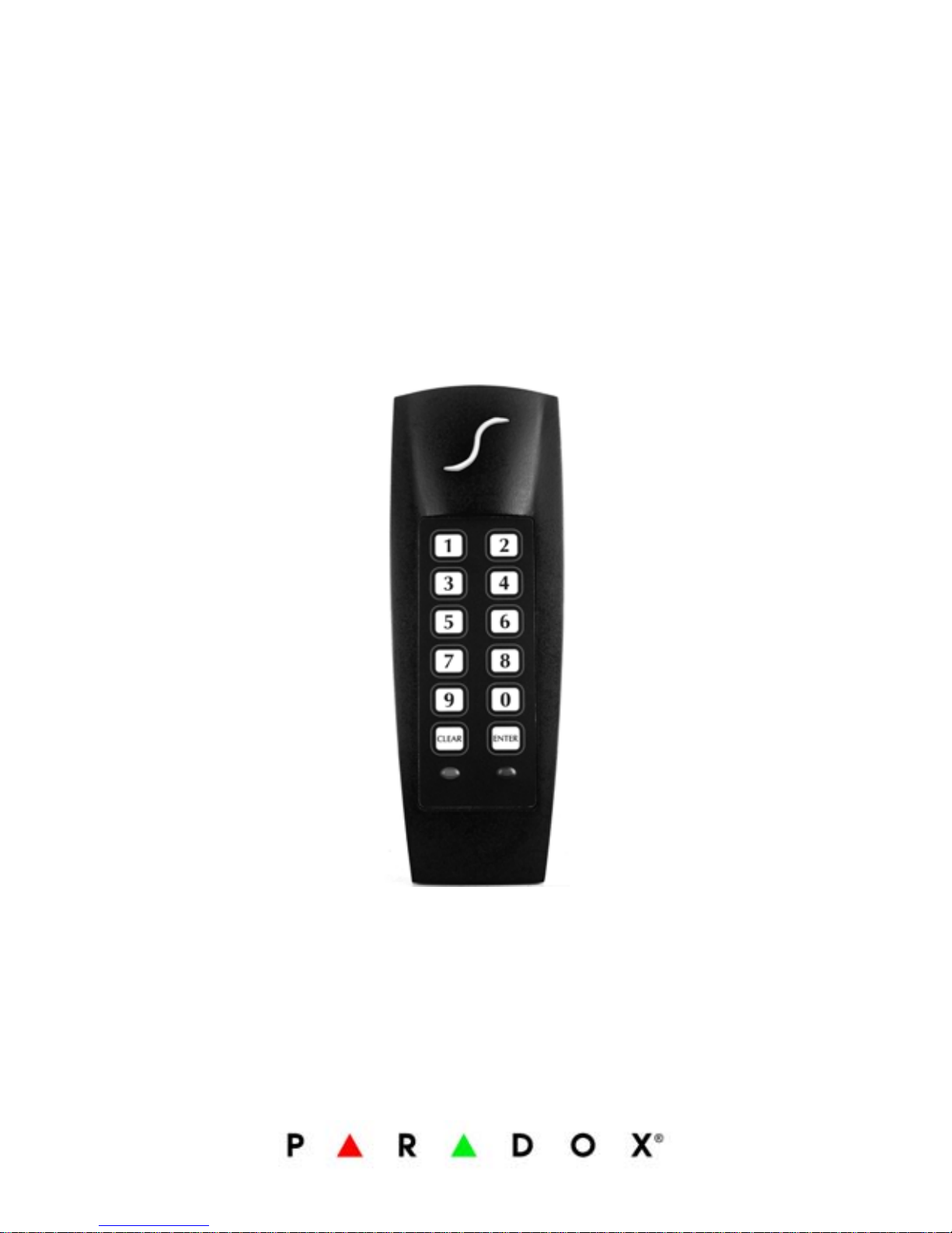
Indoor/Outdoor
Proximity Reader and
Keypad with 10cm (4in)
Read Range
Stand alone
R885S
Installation and Operating Instructions
V1.1
Page 2

Page 3

R885S 1
TABLE OF CONTENTS
Installation .............................................. 2
Mounting and Wiring ......................................... 2
Mounting on Metal Surfaces ............................... 3
Technical Specifications ..................................... 3
Feedback ......................................................... 7
Resetting to Default .......................................... 7
Card Presentation Test ...................................... 8
System Programming ............................... 9
Section [001] Card/Code Options ...................... 10
Section [002] Door Lock Control ......... .............. 10
Section [003] Access Granted Options ............... 11
Single Access Gr anted .................................. 11
Dual Access Granted .................................... 11
Dual Access Granted with Dual Panic Disarm ... 12
Section [004] Display on Card Read .................. 12
Section [005] Keypad Lockout .......... ................ 13
Section [101] Buzzer Setting ............................ 13
Section [102] Face Light Intensity ..................... 13
Section [103] Face Light Operation ........ ........... 14
Section [104] Face Light Colour ........ ................ 14
Section [200] Changing the Installer Code ......... 14
Resetting the Installer and Master Codes
to Default ................................................... 15
Master Programming ..............................16
Sections [201] and [202] Changing the
Master Codes .............................................. 16
Section [203] User Code Programming ... ........... 17
Deleting a User Code ....................................... 19
Section [204] User Code Reset ...... ................... 20
User Operation ........................................21
User Access ................................................... 21
Panic Alarm ................................................... 22
User Code Table ......................................24
Warranty ............................................... ..26
Page 4

2 Installation and Operating Instructions
INSTALLATION
To select an installation site:
• Avoid wiring the R885S’s cables in the same
conduit as AC power cables, lock power or
signal wiring.
• Reader wiring must remain a minimum of
30cm (12in) away from other wiring, such as
wiring for AC power, computer data,
telephones, electric locks, etc.
• Avoid sites within 1.1m (3.5ft) of computer
monitors or CRTs.
• Avoid sites near sources of broad spectrum
EMI noise, such as motors, pumps,
generators, DC to AC converters, AC
switching relays, power supplies and light
dimmers.
• Avoid sites near potential sources of RF
signals, such as cellular phones, two-way
radios, etc.
MOUNTING AND WIRING
Use the mounting plate as a guide to drill two
holes to secure the mounting plate and a hole for
the cable 0.95cm to 2.54cm (0.375in to 1in)
wide. Place a grommet around the edge of the
hole for the cable. Prepare the R885S’s cable by
cutting the cable jacket back 3.175cm (1.25in)
and stripping the wires back 0.635cm (0.25in).
Splice the R885S’s wires with a recommended
cable wire (see page 7) and connect as shown in
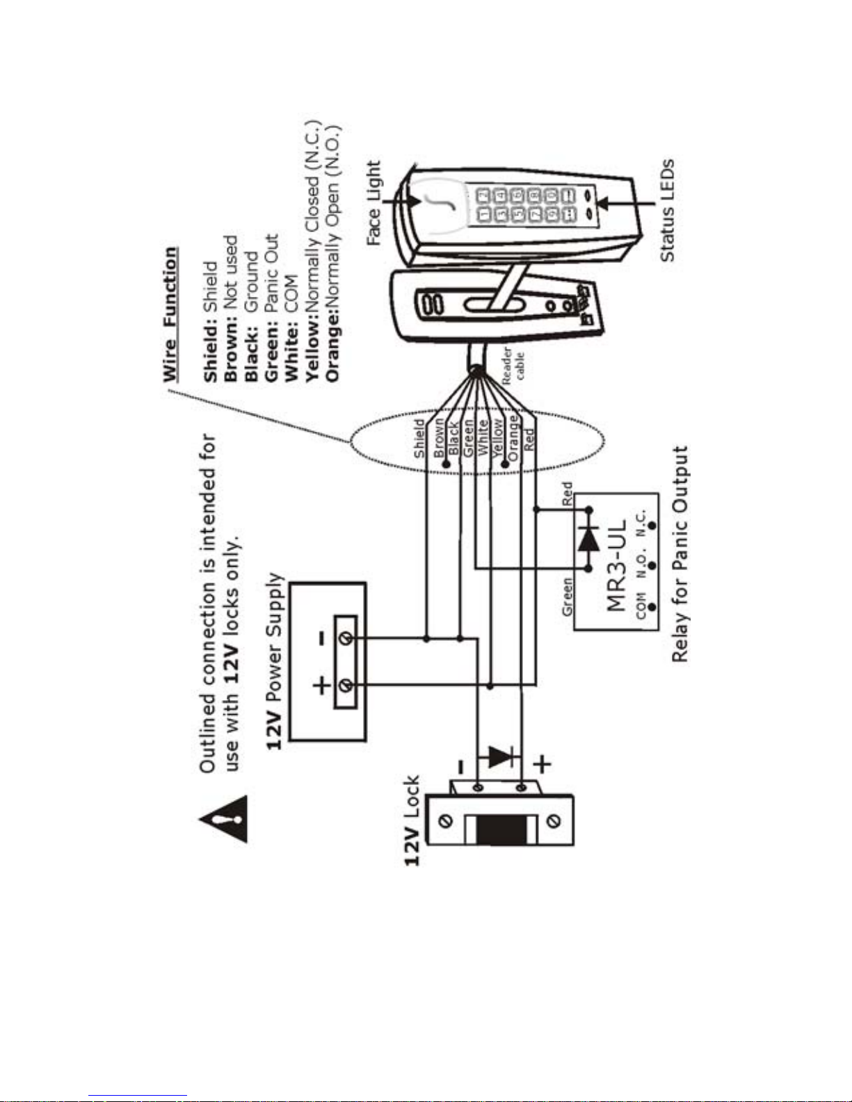
Figure 1 on page 5.
Page 5

R885S 3
MOUNTING ON METAL SURFACES
Although the read range may decrease, the
R885S can be mounted on metal. However, do
not box in or surround the card reader with any
kind of metal. If the reader must be installed in a
metal enclosure, ensure that the face of the card
reader is not covered and that at least 1.6" (4cm)
remain between the card reader and the metal on
all sides of the card reader.
TECHNICAL SPECIFICATIONS
Input Voltage: Typical: 13.8Vdc, min.:
11.0Vdc, max: 14.5Vdc
Input Current: Typical: 65mA @ 12.5Vdc,
with card: 105mA
Consumption: Typical: 812mW @ 12.5Vdc,
with card 1.31mW
Frequency: Exciter Field: 125kHz Pulse
Modulated, receive low:
12.5kHz, Receive high:
15.625KHz
Operating Temp: -25°C (-13°F) to +65°C
(+149°F)
Cable Distance: 152.4m (500ft)
Suggested Cables: 22AWG, 0.8mm, Multi-
conductor, Alpha 5196, 5198
18AWG, 1.2mm, Multi-
conductor, Alpha 5386, 5388
Belden 9553, 18AWG, 6-
conductor, stranded w/overall
shield
Indicators: Beeper, red LED and green
LED
Page 6

4 Installation and Operating Instructions
For CR-R885-S: red and
green Face Light
For R885S: blue and green
Face Light
Weight: 280g (9.8 oz.)
Material: Black, UV resistant, ABS
plastic
Dimensions: 99.5mm (5.75") x 118.5mm
(2") x 19.5mm (1")
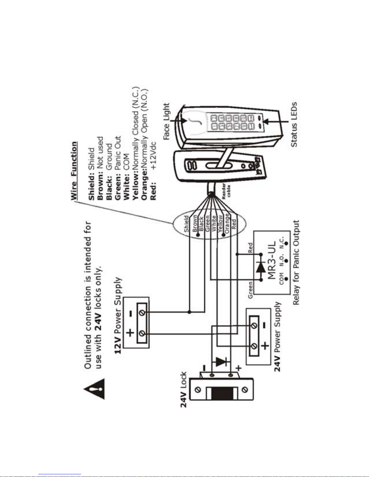
Wire Function: Brown: Not used
Black: G round
Green: Pan ic Out
White: COM
Yellow: N ormally Closed
(N.C.)
Orange: Normally Open
(N.O.)
Red: +12 Vdc
Page 7
R885S 5
Figure 1: Connection drawing (12V Locks)
Page 8
6 Installation and Operating Instructions
Figure 2: Connection Drawing (24V Locks)
Page 9

R885S 7
FEEDBACK
Depending on the programming mode chosen,
the feedback will differ. In the section System
Programming on page 9 and Master Programming
on page 16, the combinations of visual feedback
and beep tones are specified step by step.
Visual Feedback: When information is entered
on the reader’s keypad, the red and/or green
LEDs will flash, turn ON or turn OFF depending on
the step reached in programming.
Confirmation Beep: When an operation is
successfully entered, the reader emits a rapid
series of beep tones (“beep-beep-beep-beepbeep”).
Rejection Beep: When the system reverts to a
previous status or an operation is incorrectly
entered, the reader emits one long beep tone
(“beeeeeeeeeep”).
RESETTING TO DEFAULT
To reset all sections to factory defaults,
disconnect reader’s power supply. Press and hold
the [1] and [2] keys simultaneously while re-
connecting its power supply. The reader will emit
a confirmation beep. Repeat this procedure a
second time holding the [3] and [4] keys.
Sections are reset when the reader emits the
second confirmation beep.
Page 10
8 Installation and Operating Instructions
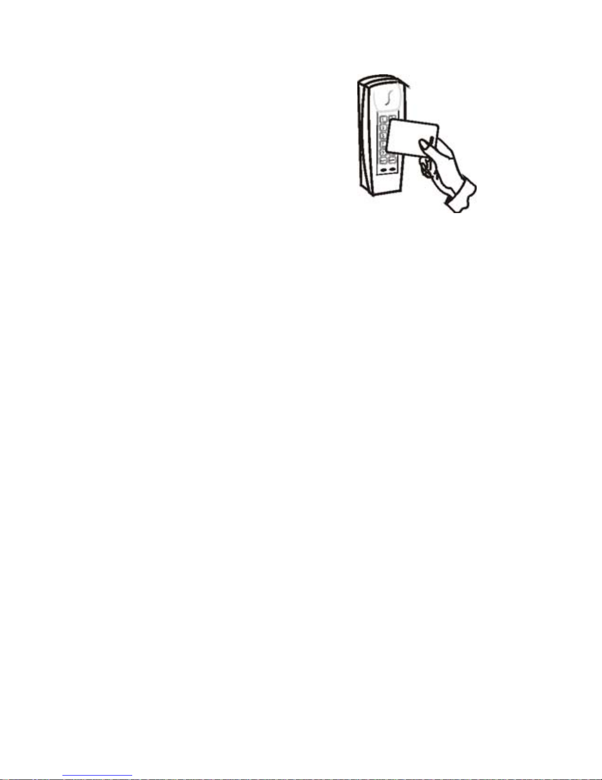
CARD PRESENTATION TEST
Place the card parallel to the
R885S reader (as shown in
the figure) and move it
toward the reader until the
reader provides audio or
visual feedback.
Page 11

R885S 9
SYSTEM PROGRAMMING
The Installer Code (default: 000000) can
program a new Installer Code PIN in section
[200] and program all the system sections from
[001] to [005] and [101] to [104].
To Enter System Programming Mode:
1. Press and hold the [
CLEAR] key for 4 seconds.
The reader emits a confirma tion beep, the
green LED turns ON and the red LED turns
OFF.
2. Enter the [
INSTALLER CODE] and press the
[
ENTER] key.
Reader emits a confirmation beep and the
green LED flashes.
3. Enter the 3-digit [
SECTION] and press the
[
ENTER] key.
Reader emits a confirmation beep and green
LED becomes constant.
4. Enter the required [
DATA] and press the
[
ENTER] key.
The reader emits a confirmation beep and the
green LED flashes.
Note: It may take several seconds for the
module to register the command and emit a
confirmation beep.
5. To program another section, repeat steps
3 and 4. To exit, press and hold the [
CLEAR]
key for 4 seconds.
The reader emits a rejection be ep and the
green LED turns OFF.
Page 12

10 Installation and Operating Instructions
SECTION [001] CARD/CODE OPTIONS
The R885S can function as a reader only, as a
keypad only or as a combined reader and
keypad. Option [3] by default
When a Card/Code option is set, it may
require several seconds for the system to
update the programming. The reader emits a
confirmation beep once the modification is
complete.
SECTION [002] DOOR LOCK CONTROL
The Door Lock Control determines the length of time
the locking device remains unlatched after an
Access Granted. When [0] is programmed, the lock
is unlatched after an Access Granted and remains
unlatched until it receives a second Access Granted
(functions like a key). When [1] to [5] is
programmed, the lock remains unlatched for the
defined time period. Option [2] by default.
Enter Description
[0] Keypad and reader disabled. For
programming only.
[1] Reader only. Present valid card to the
reader for Access Granted.
[2] Keypad only. Enter valid code on the
keypad for Access Granted.
[3] Keypad and reader enabled. A user must
present BOTH a valid card AND enter a
valid code to receive an Access Granted.
Page 13

R885S 11
SECTION [003] ACCESS GRANTED OPTIONS
The Access Granted Options depend on the Card/
Code Options set in section [001]. Option [0] by
default.
Single Access Granted
When [0] is programmed, one user can obtain
Access Granted by using a valid card, code or
both depending on the Card/Code Option set.
Dual Access Granted
When [1] is programmed, two users are required
to obtain Access Granted. Each user must use a
valid card, code or both depending on the Card/
Code Option set. Only one user is required to
disarm a Panic Alarm.
Enter Description
[0] Card/Code Controlled Free Access
(Latched).
[1] 1 second.
[2] 5 seconds.
[3] 10 seconds.
[4] 20 seconds.
[5] 60 seconds.
Enter Description
[0] Single Access Granted.
[1] Dual Access Granted.
[2] Dual Access Granted with Dual Panic
Disarm.
Page 14

12 Installation and Operating Instructions
Example: When the reader and the keypad are
enabled, User 1 must present a valid card and
enter a valid code and then User 2 must present
a valid card and enter a valid code for Access
Granted.
Dual Access Granted with Dual Panic
Disarm
When [2] is programmed, two users are required
to obtain Access Granted (same as Dual Access
Granted) and two users are required to disarm a
Panic Alarm.
For example, a Panic Alarm is triggered, User 1
must present a valid card and enter a valid code
and then User 2 must present a valid card and
enter a valid code to disarm the alarm.
SECTION [004] DISPLAY ON CARD READ
The visual feedback when a card is presented to
the reader can be adjusted according to the
installation’s requirements. Option [3] by
default.
Enter Description
[0] Display on Card Read disabled.
[1] Red Status LED flashes.
[2] Green Status LED flashes.
[3] Red and green Status LEDs flash.
[4] Face Light flashes.
[5] Face Light and red Status LED flash.
[6] Face Light and green Status LED flash.
[7] Face Light and both Status LEDs flash.
Page 15

R885S 13
Select [0] in Section [103] Face Light
Operation on page 14 to enable options
[0] to [3] in section [004] or select [1]
in Section [103] Face Light Operation on
page 14 to enable options [4] to [7] in
section [004].
SECTION [005] KEYPAD LOCKOUT
When Keypad Lockout is enabled and the Installer
Code is entered incorrectly 3 consecutive times,
the keypad ignores all entries for 60 seconds.
Option [0] by default.
SECTION [101] BUZZER SETTIN G
The number of beep tones emitted as a response
to a card being presented to the reader can be
adjusted from 0 (disabled) to 7 (7 rapid beep
tones). Option [3] by default.
SECTION [102] FACE LIGHT INTENSITY
The Face Light’s illumination can be adjusted
according to the installation’s requirements from
0 (off) to 8 (brightest). Option [4] by default.
Enter Description
[0] Keypad Lockout disabled.
[1] Keypad Lockout enabled.
Page 16
14 Installation and Operating Instructions
SECTION [103] FACE LIGHT OPERATION
The Face Light can be set to remain illuminated
continually or can follow the state of the Status
LEDs. Option [1] by default.
If [0] in section [103] is selected, this will
override options [4] to [7] in Section
[004] Display on Card Read on page 12. In
addition, if [1] in section [103] is
selected, this will override [0] to [3] in
Section [004] Display on Card Read on
page 12.
SECTION [104] FACE LIGHT COLOUR
The Face Light’s colour can be modified as
desired. Option [0] by default.
This feature only applies when Face Light
Operation programmed in Section [103] is
set for Option [0]: Face Light constant.
SECTION [200] CHANGING THE INSTALLER
CODE
The Installer Code (000000 by default) is used to
program all the system’s sections, but cannot
program the Master and User Codes (see
Enter Description
[0] Face Light constant.
[1] Face Light follows Status LEDs.
Enter Description
[0] Blue Face Light.
[1] Green Face Light.
Page 17

R885S 15
page 16). In section [200] enter six digits where
each digit can be any value from 0 to 9.
RESETTING THE INSTALLER AND MASTER
CODES TO DEFAULT
To reset the Installer Code, Master Code 1 and
Master Code 2 to factory defaults, disconnect the
reader’s power supply. Press and hold the [3]
and [4] keys simultaneously while re-connecting
its power supply. Installer Code, Master Code 1
and Master Code 2 are reset when the reader
emits a confirmation beep.
Page 18

16 Installation and Operating Instructions
MASTER PROGRAMMING
Master Programming Mode is used to program
Master and User Codes.
SECTIONS [201] AND [202] CHANGING THE
MASTER CODES
Master Code 1 (default: 111111) is used to
program both Master Codes, the User Codes and
the Section [002] Door Lock Control (see
page 10). Master Code 2 (default: 222222) can
program the User Codes and change its own PIN.
Master Code 2 cannot program Master Code 1 or
the Door Lock Control. In the desired section
enter the 6-digit personal identification number
(PIN) where each digit can be any value from 0 to
9.
To Change the Master Codes:
1. Press and hold the [
CLEAR] key for 4 seconds.
The reader emits a confirma tion beep, the
green LED turns ON and the red LED turns
OFF.
2. Enter [
MASTER CODE 1 or MASTER CODE 2] and
press the [
ENTER] key.
Reader emits a confirmation beep and the red
and the green LEDs flash simultaneously.
3. Enter [201] to change Master Code 1 or
[202] to change Master Code 2 and press the
[
ENTER] key.
Reader emits a confirmation beep and the
green LED becomes constant.
4. Enter the new PIN and press the [
ENTER] key.
Page 19

R885S 17
The reader emits a confirmation beep and both
LEDs flash.
5. To exit, press and hold the [
CLEAR] key for 4
seconds.
The reader emits a rejection be ep and the
green LED turns OFF.
SECTION [203] USER CODE PROG RAMMING
Master Code 1 and 2 can activate cards and
program the personal identification numbers
(PIN) for the User Codes. The R885S includes
1000 User Codes. User Code 000 to 999 can be
1 to 8 digits in length where each digit can be any
value from 0 to 9. You can use the table on
page 24 to record the User Codes.
To Program User Codes:
1. Press and hold the [
CLEAR] key for 4 seconds.
The reader emits a confirma tion beep, the
green LED turns ON and the red LED turns
OFF.
2. Enter [
MASTER CODE 1 or MASTER CODE 2] and
press the [
ENTER] key.
Reader emits a confirmation beep and the red
and the green LEDs flash simultaneously.
3. Enter [203] and press the [
ENTER] key.
Reader emits a confirmation beep and the red
and the green LEDs flash alternately.
4. Enter the number of the desired User Code.
Press the [
ENTER] key.
The reader emits a confirmation beep and the
green LED turns ON. If the red LED turns ON,
Page 20

18 Installation and Operating Instructions
the section is e mpty. If the r ed LED stays OFF,
a User Code is already programmed in the
section.
5. Program the card, access code (or both
combined) according to the option selected in
section [001] (see page 9). Then enable one of
the following options:
• Reader only: present the card to the reader
without pressing the [
ENTER] key. The reader
will automatically advance to the next User
Code.
• Keypad only (PIN is less than 8 digits): enter
PIN and press the [
ENTER] key to advance to
the next User Code.
• Keypad only (PIN is more than 8 digits):
enter PIN, the reader will automatically
advance to the next User Code after you
have entered the 8th digit.
• Keypad and reader: present the card to the
reader followed by the PIN. Press the
[
ENTER] key to advance to the next User
Code.
6. The reader automatically advances to the next
sequential user position. Return to step 5 to
program another card.
To e xit:
•Press [
CLEAR] key. The red and green LEDs
will flash alternately.
• Press the [
CLEAR] key a second time. Both
LEDs will flash simultaneously.
• Press and hold the [
CLEAR] key a third time
to exit this section.
Page 21

R885S 19
When you press the [CLEAR] key in step 5:
If the User Code is not programmed, the
R885S will revert to s tep 4. If a card or PIN
was entered, press the [
Enter] key to
confirm the removal and advance to the
next user code or press the [
CLEAR] key to
enter a new user code. If you press and
hold the [
CLEAR] key you will exit this
section entirely.
DELETING A USER CODE
User Codes can be deleted individually. When the
User Code is deleted, a new card and/or PIN can
be programmed in the section.
To Delete User Codes:
1. Press and hold the [
CLEAR] key for 4 seconds.
The reader emits a confirma tion beep, the
green LED turns ON and the red LED turns
OFF.
2. Enter [
MASTER CODE 1 or MASTER CODE 2] and
press the [
ENTER] key.
Reader emits a confirmation beep and the red
and the green LEDs flash simultaneously.
3. Enter [203] and press the [
ENTER] key.
Reader emits a confirmation beep and the red
and the green LEDs flash alternately.
4. Enter the 3-digit User Code (not the user’s
PIN) that you wish to delete. Press the
[
ENTER] key.
The reader emits a confirmation beep and the
green LED turns ON. The red LED should be
OFF, indicating that the user code has
Page 22

20 Installation and Operating Instructions
previously been programmed with a PIN/card.
If the red LED is ON, the user code is free.
5. Press the [
CLEAR] key.
The red LED flashes.
6. Press the [
ENTER] key to confirm the removal
and advance to the next section.
To exit:
•Press [
CLEAR] key. The red and green LEDs
will flash alternately.
• Press the [
CLEAR] key a second time. Both
LEDs will flash simultaneously.
• Press and hold the [
CLEAR] key a third time
to exit this section.
SECTION [204] USER CODE RESE T
User Code Reset is used to delete all the User
Codes (from User Code 000 to 999).
To Reset all User Codes:
1. Press and hold the [
CLEAR] key for 4 seconds.
The reader emits a confirma tion beep, the
green LED turns ON and the red LED turns
OFF.
2. Enter [
MASTER CODE 1 or MASTER CODE 2] and
press the [
ENTER] key.
Reader emits a confirmation beep and the red
and the green LEDs flash simultaneously.
3. Enter [204] and press the [
ENTER] key.
Reader emits a confirmation beep, the green
LED turns ON and the red LED turns OFF.
4. Press the [1] key and then press the [
ENTER]
key to confirm the reset.
Page 23

R885S 21
Note: It may take several seconds for the
module to register the command and emit a
confirmation beep.
When the User Codes are reset, it may
require several seconds for the system to
update the programming. The reader emit s
a confirmation beep once the modification
is complete.
USER OPERATION
USER ACCESS
Access is granted according to the Card/Code
Option (see page 10) and the Access Granted
Option set (see page 11).
Single Access
Granted
Dual Access
Granted
Reader
Only
1 user: user
presents a valid
card to the
reader.
2 users: each user
presents a valid card
to the reader.
Keypad
Only
1 user: user
enters a valid
User Code on
the keypad and
presses the
[
ENTER] key.
2 users: each user in
turn enters a valid
User Code on the
keypad and presses
the [
ENTER] key.
Page 24

22 Installation and Operating Instructions
The second user’s card and/or User Code
must be different from the first.
PANIC ALARM
A panic alarm can be generated by pressing and
holding the [
CLEAR] and [ENTER] keys for 2
seconds. The Panic Alarm will activate the panic
output (see Figure 1 on page 5). Access will not
Reader
and
Keypad
1 user: user
presents a valid
card to the
reader. The
reader emits a
confirmation
beep and the
green Status
LED flashes.
User must enter
a valid User
Code on the
keypad and
press the
[
ENTER] key
within 10
seconds.
2 users: the first
user presents a valid
card to the reader.
The reader emits a
confirmation beep
and the green Status
LED flashes. The first
user must enter a
valid User Code on
the keypad and press
the [
ENTER] key
within 10 seconds.
The reader will emit
a Confirmation Beep
and the red Status
LED flashes slowly.
The second user has
30 seconds to
present a valid card
to the reader and
then enter a valid
User Code.
Single Access
Granted
Dual Access
Granted
Page 25

R885S 23
be granted to users until the Panic alarm is
disarmed. Disarming a Panic Alarm depends on
the Card/Code Option (see page 10) and Access
Granted Option (see page 11). To disarm a Panic
Alarm:
The second user’s card and/or User Code
must be different from the first.
Single
Access
Granted
Dual
Access
Granted
Dual Access
Granted with
Dual Panic
Disarm
Reader
Only
Present 1 valid
card to the reader
2 users: each user
presents a valid
card to the reader.
Keypad
Only
Enter 1 valid User
Code and
press the [
ENTER]
key
2 users: each user
enters a valid User
Code and presses
the [
ENTER] key.
Reader
and
Keypad
Present 1 valid
card to the reader
then enter 1 valid
User Code and
press the [
ENTER]
key
2 users: the first
user presents a
valid card to the
reader. then must
enter a valid User
Code and press
the [
ENTER] key.
The second user
has 30 seconds to
present a valid
card to the reader
and then enter a
valid User Code.
Page 26

24 Installation and Operating Instructions
USER CODE TABLE
Use this table to keep a record of the User Codes.
If you require extra pages, photocopy this table.
The PIN column is provided for your convenience,
however, we recommend not using it for security
reasons.
User
Code
Name Card
Number
PIN
(optional)
Page 27

R885S 25
User
Code
Name Card
Number
PIN
(optional)
Page 28

26 Installation and Operating Instructions
WARRANTY
For complete warranty information, please visit
www.paradox.com/terms. Your use of the Paradox product
signifies your acceptance of all warranty terms and conditions.
For the latest product approvals, such as UL and CE, please visit
www.paradox.com. © 2010 Paradox Ltd. All rights reserved.
Specifications may change without prior notice.
PATENTS
One or more of the following US patents may apply: 7046142,
6215399, 6111256, 6104319, 5920259, 5886632, 5721542,
5287111, 5119069, 5077549 and RE39406 and other pending
patents may apply. Canadian and international patents may also
apply.
Page 29

R885S 27
Notes
Page 30

Page 31

Page 32

Printed in Canada - 11/2010 PARADOX.COM R885S-EI05
For technical support in Canada or the U.S., call 1-800-
791-1919, Monday to Friday from 8:00 a.m. to 8:00
p.m. EST. For technical support outside Canada and the
U.S., call 00-1-450-491-7444, Monday to Friday from
8:00 a.m. to 8:00 p.m. EST.
Please feel free to visit our website at
www.paradox.com.
 Loading...