

Page 1
PMD2P-EI01 - Printed in Canada 06/2013
PMD2P: Wireless PIR Motion Detector with Built-in Pet Immunity V1.0
Detector Settings - Quick View
Detector Settings - Details
Sensitivity
S2 (Slider) High = High sensitivity (default)
Low = Low sensitivity
Fast/Slow Mode
JP1 (Jumper) Off = Slow mode
On = Fast mode (default)
LED Feedback
JP2 (Jumper) Off = Disabled
On = Enabled (default)
Sensitivity - S2 (Slider)
High Sensitivity In high sensitivity mode, you should not be able to cross more than one complete zone (consisting
of two beams - left and right sensor elements) in the coverage area with any kind of movement. Use
this setting for the majority of installations.
Low Sensitivity In low sensitivity mode, the amount of movement required to generate an alarm is doubled. The use
of low sensitivity mode is recommended in areas where the incidence of false alarms may be
greater.
Fast/Slow Mode - JP1 (Jumper)
Slow Mode Recommended in areas where the incidence of false alarms may be greater.
Fast Mode Recommended for the majority of installations.
LED Feedback - JP2 (Jumper)
Alarm The red LED will illuminate for a period of 3 seconds whenever the motion detector detects any
kind of movement.
Low Battery The PMD2P performs a battery test every 12 hours. If battery voltage drops below a certain level,
the red LED flashes at 8 second intervals and the motion detector will send a low battery signal to
the receiver. A trouble is generated and then transmitted to the central monitoring station.
Signal
Transmission
The red LED blinks fast when transmitting.
Description
The Paradox PMD2P is an analog single-optic PIR motion detector with built-in
pet immunity for use with Magellan wireless receivers/transceivers. The PMD2P
is immune to animals weighing up to 18kg (40 pounds), and features automatic
temperature compensation.
The PMD2P is battery-powered and features an innovative three minute energy
save mode (after two detections within a five-minute period). Also, the ALIVE
software in the PMD2P ensures that the alarm LED continues to display when it
is in energy save mode without compromising battery life.
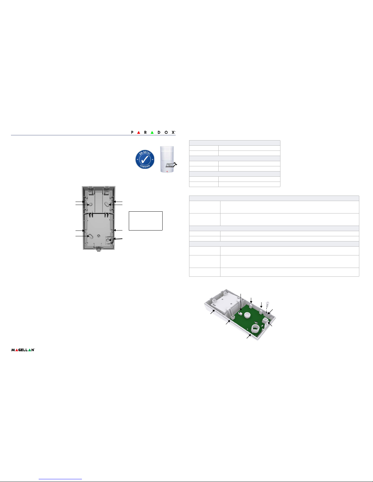
Installation
At the installation height of 2.1m (7ft)
±10%, the PMD2P provides full
coverage from 1.2m (3.9 ft) to 11m
(36 ft). Mounting lower than
recommended height will decrease
the long range performance; higher
will decrease short range
performance. Do not obscure the
detector, partially nor fully.
IMPORTANT: Do not touch the
sensor as this could result in
malfunction. Clean the sensor
surface using a soft cloth with pure
alcohol. Also, avoid bending,
cutting, or altering the antenna or
mounting the detector near metal as
this may affect transmission.
A - Corner mount
B - Flat surface mount
C - Wall tamper hole
A
B
A
B
A
B
A
C
Dual Tamper Mechanism - Wall and Cover
The PMD2P is equipped with dual tamper protection; an alarm is generated if the fr ont cover is removed or if the
detector is removed from the wall. In order for the wall tamper removal feature to be functional, a screw needs to be
inserted in the wall tamper hole (see PCB Overview at right).
Powering the Wireless Detector
Verifying proper polarity, insert three “AAA” alkaline batteries into the motion detector’s battery compartment. To replace
the batteries, remove the old batteries, then press and release the tamper switch and wait 60 seconds in order to reinitialize the unit. After initialization is complete, insert batteries while verifying proper polarity (verify proper polarity on
battery compartment connector as well). IMPORTANT: Make sure that when reinstalling the battery compartment that
the batteries are facing the back-plate.
Power-up Sequence
After inserting the batteries, a power-up sequence begins (lasting 10-20 seconds). During this time, the red LED flashes
and the detector will not detect an open zone or tamper.
Signal Strength Test
In order to verify proper signal reception, perform a signal strength test as described in the receiver’s Reference and
Installation Manual. Prior to performing the test, ensure the batteries have been installed. Also verify that the motion
detector has been assigned to a zone according to the instructions in the receiver’s Reference and Installation Manual.
If the transmission is weak, relocating the transmitter by a few inches ca n greatly improve the reception.
PCB Overview
Battery
compartment
S2
Antenna
JP1
JP2
Anti-tamper
switch
Battery
connector
Wall tamper
hole
Page 2
PMD2P-EI01 - Printed in Canada 06/2013
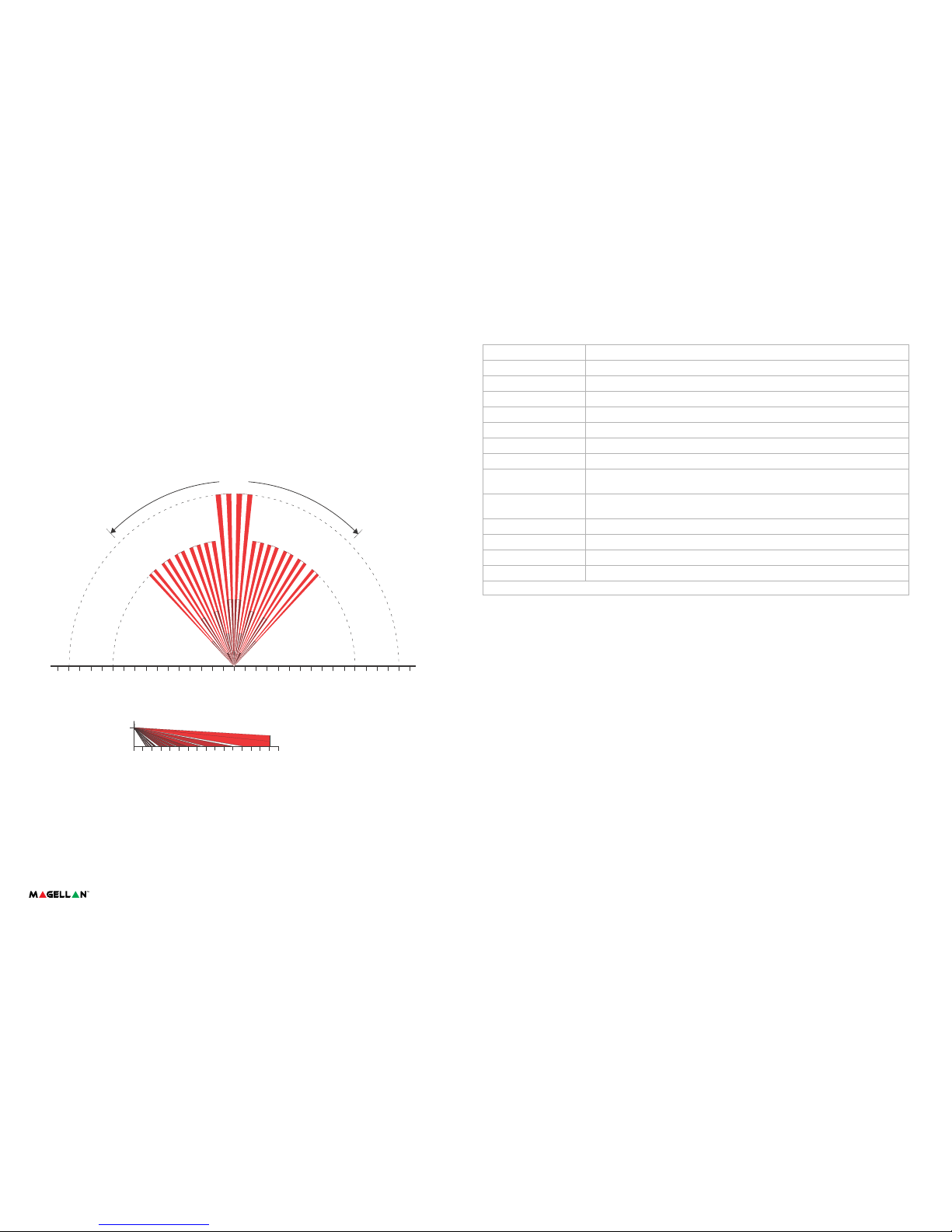
Specifications
Sensor Type Dual rectangular element
Coverage 88.5° - 11m (36ft) x 11m (36ft); Center bea ms: 15m (49ft)
Pet Immunity 18kg (40lbs)
RF Frequency 433 or 868 MHz with Magellan only
Lens 2nd generation Fresnel lens, LODIFF® segments
Walk Speed 0.2m to 3.5m/s (0.6ft to 11.5ft/s)
Battery Type & Life 3 x 1.5vDC “AAA” alkaline batteries; 2 years*
Current Rating 31uA standby / 15mA alarm
Transmitter Range 35m (115ft) with MG6130 / MG6160
70m (230ft) with MG5000 / MG5050 / RTX3; in a typical residential environment
Operating Temp. &
Humidity
0°C to 50°C (32°F to 122°F) / 5 to 90% max.
Dimensions & Weight 6.5 x 12.5 x 5.2cm (2.5 x 4.9 x 2.0 in) / 105 g (3.7 oz) with batteries
RF Immunity EN 50130-4: 10V/m 80MHz to 2.7GHz
Compatibility See paradox.com for compatibility details
Certification EN 50131 Grade 2 Class II; Certification body Intertek
* Battery life expectancy will vary according to the amount of traffic (movement) detected. Higher traffic levels wil l lower battery life.
Alive Software
To conserve the motion detector’s battery life, if the motion detector transmits two open zone signals (LED on for 3s)
within a five-minute period, the detector will fall into Energy Save Mode for approximately three minutes and will not
transmit any alarm signals. The red LED will continue to flash to indicate a detection. If the detector’s cover is removed
and then replaced while in Energy Save Mode, the first detection will trigger an alarm signal.
Walk-testing
To activate Walk-test Mode for three minutes, power up the detector or open and close the detector’s cover. With
sensitivity set to High (S2 = High), at 20°C, crossing more than one complete zone (consisting of two beams left and
right sensor detecting elements) with slow/fast walking or running shou ld initiate an alarm. With sensitivity set to Low
(S2= Low), the amount of movement required to generate an alarm is doubled.
Beam Pattern
2.1m
(6.8ft)
0
0
2m
(6.6ft)
2m
(6.6ft)
2m
(6.6ft)
4m
(13.1ft)
4m
(13.1ft)
4m
(13.1ft)
6m
(19.7ft)
6m
(19.7ft)
6m
(19.7ft)
8m
(26.3ft)
8m
(26.3ft)
8m
(26.3ft)
10m
(32.8ft)
12m
(39.4ft)
14m
(45.9ft)
16m
(52.5ft)
12m
(39.4ft)
14m
(45.9ft)
16m
(52.5ft)
10m
(32.8ft)
10m
(32.8ft)
12m
(39.4ft)
14m
(45.9ft)
16m
(52.5ft)
88.5°
Warranty : For complete warranty information on this product, please refer to the Limited Warranty Statem ent found on the Web site www.paradox.com/terms. Your use of the Paradox
product signifies your acceptance of all warranty terms and conditions.
© 2013 Paradox Ltd. All rights reserved. Specifications may change without prior notice.
Patents: One or more of the following US patents may apply: 7046142, 6215399, 6111256, 6104319, 5920259, 5886632, 5721542, 5287111, and RE39406 and other pending patents
may apply. Canadian and international patents may also apply.
 Loading...