

Page 1
PCS300 Universal IP
Reporting Module
V1.0
Reference and Installation Manual
Page 2

Patents: One or more of the following US patents may apply:
7046142, 6215399, 6111256, 6104319, 5920259, 5886632,
5721542, 5287111, 5119069, 5077549 and RE39406 and other
pending patents may apply. Canadian and international patents
may also apply.
Trademarks: Paradox is a trademark of Paradox Security Systems
Ltd. or its affiliates in Canada, the United States and/or other
countries.
Certification: For the latest information on products approvals,
such as UL and CE, please visit www.paradox.com.
Warranty: For complete warranty information on this product
please refer to the Limited Warranty Statement found on the
website www.paradox.com/terms. Your use of the Paradox
product signifies your acceptance of all warranty terms and
conditions.
© 2010 Paradox Security Systems Ltd. All rights reserved.
Specifications may change without prior notice.
Page 3

Page 3
Table of Contents
Chapter 1: Introduction ........................................ 4
Features....................................................................... 5
Chapter 2: Overview ............................................ 7
Module Components - Front View ............................... 7
Module Components - Inside View .............................. 8
Module Components - Bottom View ............................ 9
LED Feedback ........................................................... 10
Specifications............................................................. 11
Chapter 3: Connections ..................................... 12
GPRS12 Plug-In Communicator Module ................... 12
GPRS12 Module SIM Card Connection..................... 14
Connections for Reporting ......................................... 15
Optional Power Supply Connections ......................... 16
Chapter 4: Installation ....................................... 17
Wall-Mount Installation............................................... 17
Antenna Extension Installation................................... 18
Chapter 5: Firmware Upgrades .......................... 19
Accessing the In-Field Paradox Upgrade Software
Application ................................................................. 19
On-Site Firmware Upgrade (IP) ................................. 20
Remote Firmware Upgrade (GPRS).......................... 22
Chapter 6: PCS300 Web Interface Page ............. 25
Index ................................................................. 26
Page 4

Page 4
Introduction
Chapter 1: Introduction
The PCS300 Universal IP Reporting Module provides security
control panels with wireless communication capabilities to
report system events via IP and/or GPRS (using the GPRS12
Plug-In Communicator Module). System events can be
reported to up to two Paradox IPR512 GPRS/IP Monitoring
Receivers.
Configuring and monitoring the status of the PCS300 is done
using the PCS300 Web Interface page (via a web browser).
From the PCS300 Web Interface page, up to two separate,
unique reporting sequences can be defined, each one linked
to a specific phone number. Each reporting method can be
programmed to perform a specific number of attempts before
switching to alternate backup reporting methods.
The PCS300 can also be programmed to send SMS text
notifications when an input is activated or deactivated and/or
when a trouble occurs. The PCS300’s firmware can be
upgraded on-site (IP) or remotely through IP or GPRS (via the
GPRS12 Module) using the In-Field Paradox Upgrade
Software application.
Page 5

Page 5
Introduction
Features
• Report events via IP or GPRS (requires GPRS12 Plug-In
Communicator Module)
• Report in conjunction with landline or as a backup
• Supports two IPR512 GPRS/IP Monitoring Receivers; each
with separate, unique reporting sequences
• Module configuration and status via the PCS300 Web
Interface
• Support for up to two inputs with report activation capability
including SMS notification
• Firmware upgrades via IP or GPRS
• Supports standard GSM provider SIM cards
• Report via SMS (up to 8 cell phone numbers)
• Supports multiple languages for both the Web Interface
and SMS
• 256-bit (AES) encryption for GPRS/IP reporting and Web
Interface
Page 6

Page 6
Introduction
Included Items
• Phillips screws for top cover (4x)
• Green 4-pin removable connector
• Black 4-pin removable connector
• Rubber grommet
GPRS12 Plug-In Communicator Mod ule (optional)
• GPRS12 Module
• GSM Quad-Band antenna
• Lock washer
• Washer
Required/Optional Items
• Active standard GSM provider SIM card (required for GPRS
reporting)
• Antenna extension (optional when using the GPRS12
Module)
• 12 Vdc external power source (required)
Compatibility
Compatible with all security system control panels that support
CID reporting.
Page 7
Page 7
Overview
Chapter 2: Overview
This section provides an overview of the PCS300 Universal IP
Reporting Module. It covers technical specifications, lightemitting diode (LED) functionality, and an overview of the
PCS300 system components.
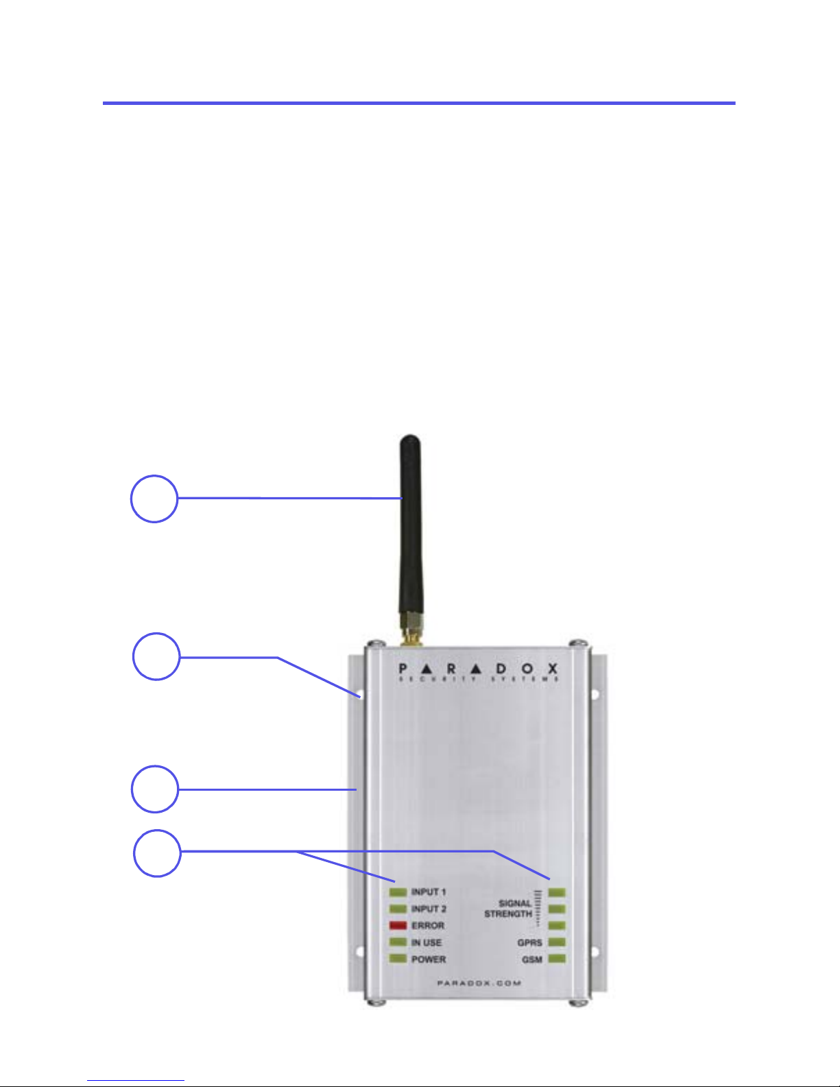
Module Components - Front View
1) GSM Quad-Band antenna: required when using the
GPRS12 Plug-In Communicator Module
2) Mounting holes
3) Durable aluminum casing
4) Module Status Indicator LEDs
1
2
4
3
Page 8
Page 8
Overview
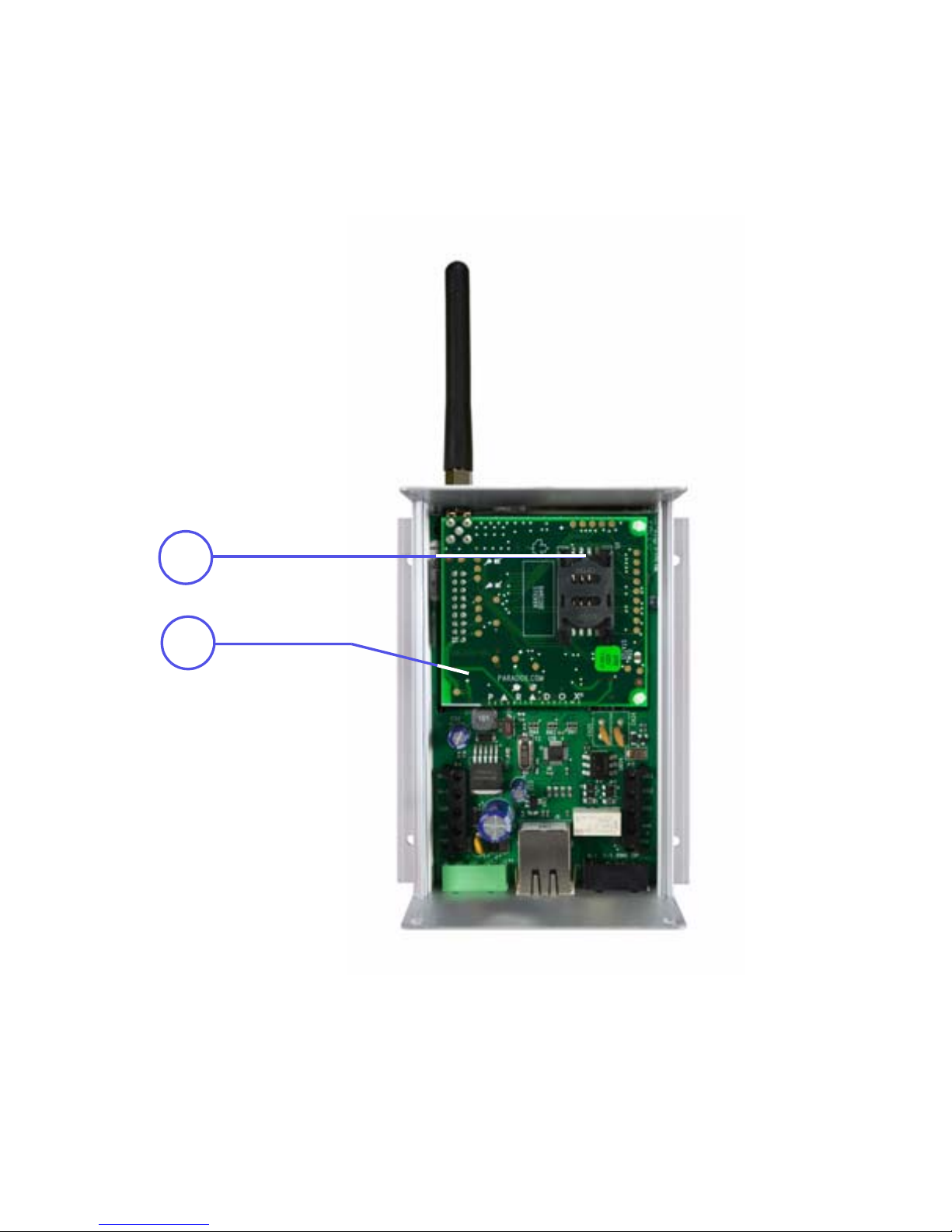
Module Components - Inside View
1) SIM Card slot: supports standard GSM provider SIM cards
2) GPRS12 Plug-In Communicator Module: optiona l for
GPRS reporting
1
2
Page 9
Page 9
Overview
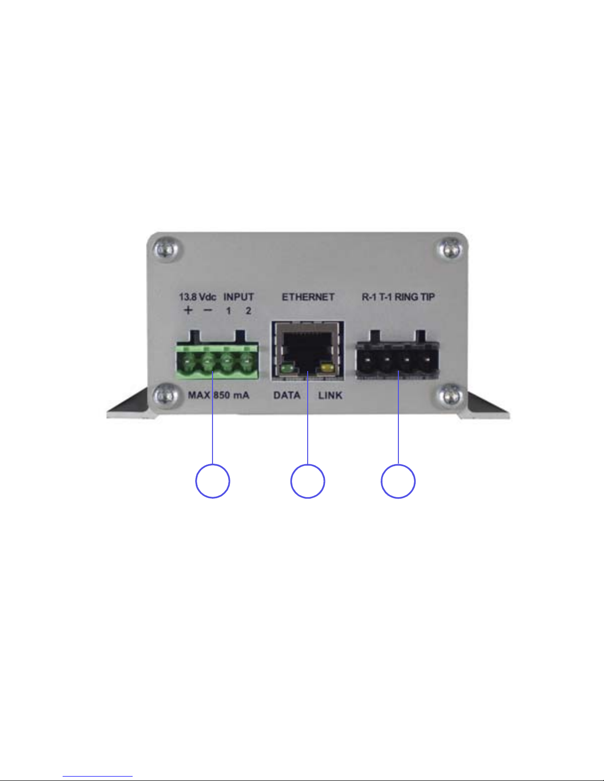
Module Components - Bottom View
1) Power/Input Terminals: used to connect the PCS300 to an
external power supply such as the PS817 (optional) and to
connect up to 2 inputs
2) Ethernet connector: used to connect the PCS300 to the IP
network
3) R-1/T-1 and Ring/Tip Terminals: used to connect the
PCS300 to the control panel and to the Telco, respectively
2
1
3
Page 10
Page 10
Overview
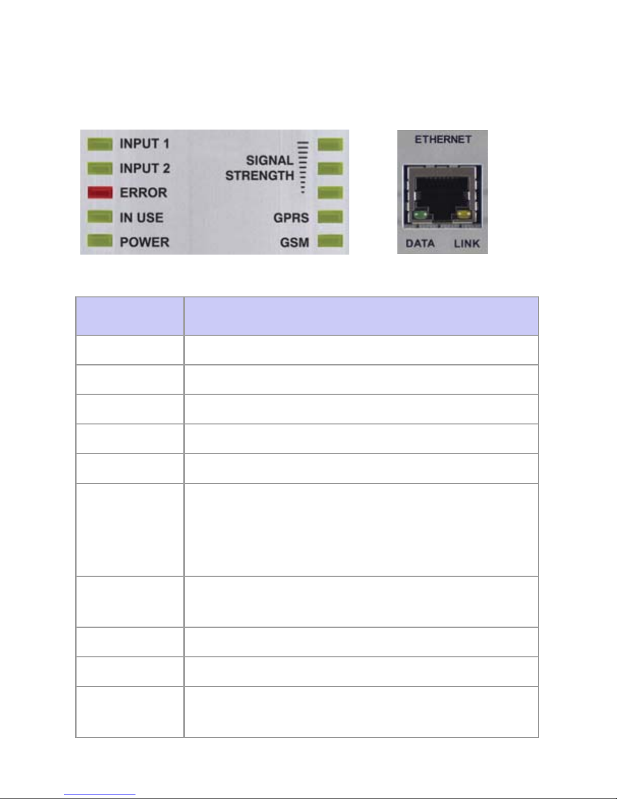
LED Feedback
The following table provides a description of the PCS300
LEDs.
LED Description
Input 1 Green: Input 1 has been activated
Input 2 Green: Input 2 has been activated
Error Red: an error has occurred on the module
In Use Green: module is communicating
Power Green: power is present
Signal
Strength
Indicates the quality of the signal
1 LED lit: weak signal (relocate module or use
an antenna extension)
3 LEDs lit: strong signal
GPRS Green: established a GPRS connection on
the GSM network
GSM Green: connected to the GSM network
Data Green flashing: module is communicating
Link Yellow: established a connection on the
Ethernet network
Bottom View LEDs
Front View LEDs
Page 11

Page 11
Overview
Specifications
The following table describes the technical specifications for
the PCS300.
Type Detail
Power Class 4 (2W) @ 850/900 MHz
Class 2 (1W) @ 1800/1900 MHz
Antenna
Bandwidth
70 / 80 / 140 / 170 MHz
Antenna Gain <3dBi; impedance 50 ohm
Input power >2W peak power
Power Input 12 Vdc (from control panel or external
power supply)
Consumption Standby: 150 mA
Average: 300 mA
Peak: 1.4A (during GPRS/GSM
transmission)
Dimensions 12 X 10.2 X 4.8 cm (4.7 X 4 X 1.9 in.)
Operating
Temperature
0ºC to 50ºC (32ºF to 122ºF)
Encryption 128-bit (MD5 and RC4) or 256-bit (AES)
SMS Protocol 8-bit (ISO 8859-1, Latin-1 character set) or
16-bit (UCS2 ISO/IEC 10646)
Page 12

Page 12
Connections
Chapter 3: Connections
The following sections guide you through the steps required to
connect the PCS300 Universal IP Reporting Module prior to
mounting the unit.
GPRS12 Plug-In Communicator Module
If you will be reporting via GPRS, the GPRS12 Module is
required. The GPRS12 Module is mounted directly onto the
PCS300’s PCB. When using GPRS reporting, certain
parameters must be defined in the PCS300 Web Interface
page. For more information on system configurations, refer to
“PCS300 Web Interface Page” on page 25.
To Install the GPRS12 Module
The following instructions are to be used only if you are
installing the GPRS12 Module because it was purchased
separately.
NOTE: Before installing the GPRS12 Module, disconnect all
power to the unit.
1) Unscrew the two top and two bottom screws holding the
top cover of the PCS300 into place.
2) Lift and remove the front cover of the PCS300.
3) Remove the two remaining screws holding the top plate
into place and remove the top plate. Remove rubber
grommet from the top plate.
4) Insert the plastic mounting rods over the holes located on
the PCS300’s PCB.
5) Place the GPRS12 Module directly onto the PCS300
plastic mounting rods and align with the 18-pin female
connector and snap into place. Slide the top plate over the
antenna connector and secure with screws. Place back
the PCS300 cover and secure with screws.
Page 13

Page 13
Connections
6) Insert lock washer over the antenna connector, followed
by the washer; tighten using pliers - turn approximately 1/8
of a turn. Screw the antenna securely into place.
Once the GPRS12 Module and the antenna have been
installed, re-assemble the PCS300 and connect power to the
unit.
1
2
1
3
4
5
6
Page 14

Page 14
Connections
GPRS12 Module SIM Card Connection
The PCS300 connects to your control panel providing wireless
communication capabilities to report system events to the
IPR512 Receiver. The PCS300 supports standard GSM
provider SIM cards. The SIM card contains all your cellular
telephone account information. In order to activate your SIM
card, you must contact your local GSM network provider.
Note: Prior to setting up your PCS300, it is important that the
Personal Identification Number (PIN) of the SIM card be
disabled. Refer to your cellular phone’s manual for more
information on how to disable the PIN.
To install the SIM card
Before installing the SIM card, remove the front cover of the
PCS300. If the cover is not installed, proceed to Step 1.
1) Slide the SIM card tray towards the top to unlock it.
2) Flip the SIM card tray open away from you. Open the SIM
card tray slowly to avoid damage to the tray.
3) Slide the SIM card into the tray with the cut-off corner
towards the top right.
4) Flip the SIM card tray closed towards you.
5) Slide the tray down to lock it into place.
OPEN
LOCK
1
3
2
4
5
SIM
Card
GPRS12
Module
Page 15

Page 15
Connections
Connections for Reporting
All required connections to the PCS300 are located at the
bottom of the unit. The PCS300 provides connections for an
external DC power source as well as connections for up to two
inputs. These inputs can then be configured via the PCS300
Web Interface page, please refer to the PCS300 Operations
Manual for more information. Additionally, connections to
provide reporting are also made from the bottom of the unit.
There are three different reporting connections that can be
made. These connections include the following:
1. GPRS
If GPRS reporting is required, ensure that the PCS300 is
equipped with the GPRS12 Module. If the GPRS12 Module
has been purchased separately, please refer to “GPRS12
Plug-In Communicator Module” on page 12 for installation
instructions. To connect the module for GPRS reporting,
ensure that the Ring/Tip terminals of the control panel are
connected to the R-1/T-1 of the PCS300.
Note: The trigger telephone number defined in the PCS300
Web Interface page and the telephone number of the control
panel number must match.
2. IP Reporting
If IP reporting is required, connect the Ethernet cable into the
Ethernet port and the other end into the network LAN. Ensure
that the LAN has access to the Internet.
3. Landline
In order to provide reporting via a conventional landline,
connect the Ring/Tip of the control panel to the R-1/T-1 of the
PCS300, and connect Ring/Tip of the PCS300 to the Telco
line.
Note: The trigger telephone number defined in the PCS300
Web Interface page and the telephone number of the control
panel number must match.
Page 16

Page 16
Connections
Optional Power Supply Connections
The PCS300 can be powered by the control panel (ensure that
the control panel can provide enough current). However, if you
want the PCS300 to function even if the control panel’s battery
is low, or if power failures are anticipated, an external power
supply with a backup battery (PS817) is highly recommended.
For more information on connecting to an external power
supply visit paradox.com.
AC AC + - TST
PS817
Transformer
Batt.
Input
1
Main Line
LAN
Input
2
Control Panel
TI P
RING
RED
GRN
Ground
Clamp
Cold Water
Pipe Grounding
or Grounded
AC Outlet
+
-
12
T1R1
R-1/T-1
To Ring/Tip
GPRS12
Module
Page 17

Page 17
Installation
Chapter 4: Installation
The following sections guide you through the steps required to
install the PCS300 Universal IP Reporting Module and how to
mount and connect the antenna.
Wall-Mount Installation
The PCS300 must be securely mounted on a wall or similar
type surface. It is important to mount the metal box as far
away as possible from any electronic equipment and that the
metal box is mounted as high as possible to ensure protection
from interference and to maximize signal quality.
To mount the PCS300
1) Use the module as a template to mark the four holes onto
the mounting surface.
2) Drill the holes.
3) Align the PCS300 and secure into place using the
appropriate hardware.
Mounting
Hole
Mounting
Hardware
Page 18

Page 18
Installation
Antenna Extension Installation
Antenna extensions are available to help improve reception.
The antenna extensions are optional for use with the GPRS12
Module. The antenna extension is sold with a wall-mounting
bracket.
To Install the Antenna Extension
1) Use the mounting bracket to mark the holes onto the
mounting surface.
2) Drill the holes and insert the antenna extension in the
bracket until it snaps into place.
3) Align the bracket and secure into place using the
appropriate mounting hardware.
Mounting Bracket
Screw Holes
Page 19

Page 19
Firmware Upgrades
Chapter 5: Firmware Upgrades
The following sections guide you through the steps required
when upgrading the PCS300 Universal IP Reporting Module’s
firmware. Firmware can be upgraded either on-site w ith a
connection to the network (IP) or remotely via the IP or GPRS
network using the GPRS12 Module.
The firmware is upgraded using the In-Field Paradox Upgrade
Software application. From this application, you can specify
the PCS300 Module to upgrade and which software version to
install. When you confirm the update, the PCS300 will be
upgraded with the selected version within minutes.
Accessing the In-Field Paradox Upgrade
Software Application
In order to access In-Field, the application must first be
installed on your hard drive. In-Field is available for download
from the Paradox website at www.paradox.com.
To Access In-Field
1) Locate the InField.exe file on your PC or double-click the
In-Field icon from your desktop.
2) If the icon is not on your desktop, double-click on the
executable file to launch the In-Field application.
The In-Field application will then be displayed on the screen.
Page 20

Page 20
Firmware Upgrades
On-Site Firmware Upgrade (IP)
To upgrade the firmware of the PCS300 on-site, a connection
to the network is required.
To Connect to the LAN Port of the PCS300
1) Connect a CAT5 network cable to the Ethernet port on the
PCS300.
2) Connect the other end of the cable to the router of the
network.
Once the connection has been established, you can now use
In-Field to upgrade the PCS300’s firmware.
To Upgrade the Firmware of the PCS300 via In-Field
The following steps describe how to upgrade the firmware of
the PCS300 using the In-Field application.
Step 1: Define Communication Settings
1) Select the Internet tab.
2) Enter the IP address of the PCS300 you wish to upgrade.
If you do not have this information, then press the Search
button and select the product from the list.
3) Define the Port. This must match the configured software
port number in the PCS300 Web Interface page.
4) Enter the IP Password. The IP Password is the password
used to log into the PCS300 Web Interface page.
Note: If you have modified the default password in the
PCS300 Web Interface page, enter the new password.
5) Proceed to Step 2: Select Devices.
Step 2: Select Device(s)
1) Click the Connect/Refresh button. A Progress dialog box
will appear. The progress dialog box detects the
connection to the network.
2) Select the Product to update from the list.
3) Proceed to Step 3: Select Firmware.
Page 21

Page 21
Firmware Upgrades
Step 3: Select Firmware
1) Select the firmware version from the list.
2) Click Browse to locate a file in another location (upgrade
files have a “.puf” extension).
3) Select the file from the Browse window. When the file is
selected, it will be displayed in the Select Firmware
window. You can also click on Get from Paradox.com to
download the latest firmware files directly from the
Paradox website.
Note: If you select a firmware version that is older than the
one currently installed on the PCS300, the system will
display a warning stating that you are about to transfer an
older firmware version. If you want to proceed, confirm the
message.
4) Proceed to Step 4: Transfer.
Step 4: Transfer
1) Click the Start Transfer button. The system will then
display a Progress dialog box.
2) Exit the application.
Once the firmware upgrade is complete, the PCS300 Module
will reboot. This may take a few minutes.
Page 22

Page 22
Firmware Upgrades
Remote Firmware Upgrade (GPRS)
The PCS300 can be upgraded remotely via the GPRS
network using the GPRS12 Module. For instructions on how to
install the GPRS12 Module, refer to “GPRS12 Plug-In
Communicator Module” on page 12.
In order to connect to the GPRS network (public and private),
a connection to the PCS300 must first be initiated by sending
an SMS text message to the module, refer to “Step 2: Select
Device(s)” on page 23. Sending the message will place the
PC into wait mode until a response is received from the
PCS300 Module, thus allowing you to begin the firmware
upgrade process.
Note: It is important that your router be set up for port
forwarding to ensure proper system functionality.
To Upgrade the Firmware of the PCS300 via In-Field
The following steps describe how to upgrade the firmware of
the PCS300 using the In-Field application.
Step 1: Define Communication Settings
1) Select the GPRS tab.
2) Enter the GPRS Password. The GPRS Password is the
password used to log into the PCS300 Web Interface
page.
Note: If you have modified the default password in the
PCS300 Web Interface page, enter the new password.
3) Define the Port. This must match the configured software
port number in the PCS300 Web Interface page.
4) Enable the “W ait for GPRS call back (Local IP Port)” radio
button.
5) Proceed to Step 2: Select Devices.
Page 23

Page 23
Firmware Upgrades
Step 2: Select Device(s)
1) Click the Connect/Refresh button. A dialog box will
appear. The dialog box provides the information required
to initiate the connection to the PCS300. In order to initiate
the connection to the PCS300, you will require a cellular
telephone and the PCS300’s SIM card phone number . For
more information on the SIM card phone number, please
refer to the PCS300 Operations Manual.
2) Enter the SMS text information to be sent to the PCS300
as it is displayed on the screen using a cellular phone.
e.g., Pparadox.A10.10.1.100.P10001
Once the connection has been established the dialog box
will close automatically.
3) Select the PCS300 Module to update from the list.
4) Proceed to Step 3: Select Firmware.
Code Description
P Defines the login password used when
logging into the PCS300 Web Interface page.
A Defines the IP address of the PC used to
initiate communication.
P Defines the Port of the PC used to initiate
communication.
Page 24

Page 24
Firmware Upgrades
Step 3: Select Firmware
1) Select the firmware version from the list.
2) Click Browse to locate a file in another location (upgrade
files have a “.puf” extension).
3) Select the file from the Browse window. When the file is
selected, it will be displayed in the Select Firmware
window. You can also click on Get from Paradox.com to
download the latest firmware files directly from the
Paradox website.
Note: If you select a firmware version that is older than the
one currently installed on the PCS300, the system will
display a warning stating that you are about to transfer an
older firmware version. If you want to proceed, confirm the
message.
4) Proceed to Step 4: Transfer.
Step 4: Transfer
1) Click the Start Transfer button. The system will then
display a Progress dialog box.
Note: Once the firmware update via GPRS has been
completed a “Transfer completed successfully” message
will appear. In order to display the new version, a system
refresh must be performed. To do so, another SMS
message must be sent to the PCS300. Press Yes if you
wish to proceed or Cancel to cancel the operation. If you
continue with the refresh, the PCS300 Module will reboot.
This may take a few minutes.
2) Exit the application.
Page 25

Page 25
PCS300 Web Interface Page
Chapter 6: PCS300 Web Interface Page
This now completes the installation for the PCS300 Universal
IP Reporting Module. The next step is to configure the
PCS300 via the PCS300 Web Interface page. From the
PCS300 Web Interface page you will:
• Configure the PCS300
• Register the PCS300 to the IPR512 GPRS/IP Monitoring
Receiver
• Define reporting sequences
• Configure inputs and set SMS notifications
• Define additional configuration settings
In order to begin the configuration of the PCS300, a
connection to a computer on the network that has access to
the Internet is required. Once the configuration of the PCS300
has been defined through the PCS300 Web Interface page,
the PCS300 module is ready for reporting. For more
information on how to configure the PCS300 via the PCS300
Web Interface page, please refer to the PCS300 Operations
Manual.
Page 26

Page 26
Index
Numerics
256-bit encryption........ 5
4-pin removable
connector .................... 6
A
Aluminum casing .........7
Antenna
bandwidth.......... 11
bracket .............. 18
connection ......... 13
connector .......... 12
extension ........... 18
B
Backup battery.......... 16
C
Call back ................... 22
Connections .............. 12
Connections for
reporting.................... 15
Consumption ............. 11
Control panel 4, 6, 11, 14,
15, 16
D
Dimensions ............... 11
E
Encryption ............. 5, 11
Error .......................... 10
Ethernet connector ...... 9
Ethernet port ........15, 20
External power supply 16
F
Firmware upgrades 5, 19
G
GPRS 5, 6, 8, 10, 11, 12
GPRS12......... 5, 6, 12, 13,
14, 15, 18, 19, 22
GSM ................ 6, 10, 11
GSM Quad-Band
antenna ...................6, 7
I
Included items .............6
In-Field ......4, 19, 20, 22
Inputs .................5, 9, 15
IP address ...........20, 23
L
LAN port ....................20
LED
Error .................. 10
GPRS ................ 10
GSM .................. 10
In Use ................10
Input 1 ............... 10
Input 2 ............... 10
Power ................ 10
Signal Strength ..10
Page 27

Page 27
LED feedback ............ 10
Lock washer .......... 6, 13
M
Module components
bottom view ......... 9
front view ............. 7
inside view .......... 8
Mounting holes ............7
Mounting rods ........... 12
Mounting the PCS300 17
O
Operating Temperature 11
P
PCS300 Web Interface
page ..12, 15, 20, 22, 23, 25
Plastic mounting rods 12
Port ................ 20, 22, 23
Port forwarding .......... 22
Power ........................ 11
Power failures ........... 16
Power input ............... 11
Power supply ....... 11, 16
Power/input terminals.. 9
R
R-1/T-1 terminals .. 9, 15
Remote firmware
upgrade ..................... 22
Required/optional items 6
Ring/Tip terminals . 9, 15
S
Signal quality............. 17
Signal Strength .......... 10
SIM card .................... 14
SIM card installation ..14
SIM card slot ............... 8
SMS ...............23, 24, 25
SMS Protocol ............11
SMS text message ....22
SMS text notifications ..4
Software port number 20
Specifications ............ 11
Start transfer ........21, 24
T
Top plate ...................12
U
Upgrade files .......21, 24
W
Wall-mount installation 17
Wall-mounting bracket 18
Washer ..................6, 13
Page 28

Notes
_________________________________________________
_________________________________________________
_________________________________________________
_________________________________________________
_________________________________________________
_________________________________________________
_________________________________________________
_________________________________________________
_________________________________________________
_________________________________________________
_________________________________________________
_________________________________________________
_________________________________________________
_________________________________________________
_________________________________________________
_________________________________________________
_________________________________________________
_________________________________________________
_________________________________________________
_________________________________________________
_________________________________________________
_________________________________________________
_________________________________________________
_________________________________________________
_________________________________________________
_________________________________________________
_________________________________________________
_________________________________________________
_________________________________________________
_________________________________________________
_________________________________________________
_________________________________________________
_________________________________________________
_________________________________________________
Page 29

Notes
_________________________________________________
_________________________________________________
_________________________________________________
_________________________________________________
_________________________________________________
_________________________________________________
_________________________________________________
_________________________________________________
_________________________________________________
_________________________________________________
_________________________________________________
_________________________________________________
_________________________________________________
_________________________________________________
_________________________________________________
_________________________________________________
_________________________________________________
_________________________________________________
_________________________________________________
_________________________________________________
_________________________________________________
_________________________________________________
_________________________________________________
_________________________________________________
_________________________________________________
_________________________________________________
_________________________________________________
_________________________________________________
_________________________________________________
_________________________________________________
_________________________________________________
_________________________________________________
_________________________________________________
_________________________________________________
Page 30

Notes
_________________________________________________
_________________________________________________
_________________________________________________
_________________________________________________
_________________________________________________
_________________________________________________
_________________________________________________
_________________________________________________
_________________________________________________
_________________________________________________
_________________________________________________
_________________________________________________
_________________________________________________
_________________________________________________
_________________________________________________
_________________________________________________
_________________________________________________
_________________________________________________
_________________________________________________
_________________________________________________
_________________________________________________
_________________________________________________
_________________________________________________
_________________________________________________
_________________________________________________
_________________________________________________
_________________________________________________
_________________________________________________
_________________________________________________
_________________________________________________
_________________________________________________
_________________________________________________
_________________________________________________
_________________________________________________
Page 31

Page 32

PCS300-EI01 03/2010 PARADOX.COM Printed in Canada
For technical support in Canada or the U.S., call 1-800-7 91-1919,
Monday to Friday from 8:00 a.m. to 8:00 p.m. EST.
For technical support outside Canada and the U.S.,
call 00-1-450-491-7444, Monday to Friday
from 8:00 a.m. to 8:00 p.m. EST.
Please feel free to visit our website at www.paradox.com.
The whole Paradox team wishes you a
successful and easy installation.
 Loading...