

Page 1
PCS250-EI07 05/2018
Installation and Programming Guide
**Compatible with Insite GOLD
and SWAN Server**
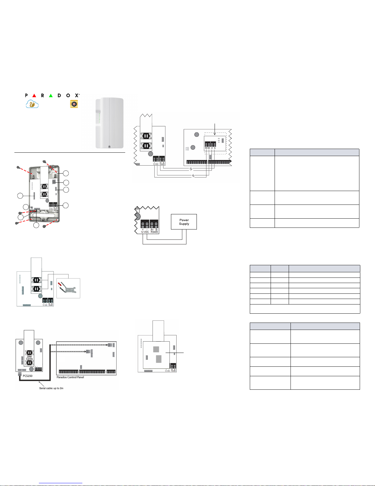
Installation
SIM Card Connection
The PCS250 supports two standard GSM provider SIM cards.
To install the SIM cards, open the SIM Card tray and insert card into slot,
as shown. SIM Card 1 is used as “Primary” and SIM Card 2 for
“Backup”.
Panel Connections
Connect the PCS250’s serial out to the serial connector on the panel.
• For GPRS reporting, connect to the Serial port of the panel.
• For GSM reporting, connect to the EBUS port of the panel.
RS485 Connection
A CVT485 module can be connected onto the control panel’s EBUS in
order to lengthen the distance (up to 300 m. / 1000 ft.) between the
panel and the PCS250. Refer to the drawing for connections.
*Optional Power Supply Connections (for RS485)
The PCS250 is designed to be powered by the control panel up to 50m
(160 ft.) with an 18 gauge wire. If you are using a CVT485 module to
increase the distance from your panel, an external power supply should
be used. Refer to the drawing below.
Antenna Extension Connection
Use an antenna extension kit to improve RF reception if your module’s
signal strength is weak. Antenna kits are purchased separately.
IP150 Connection
The PCS250 can be connected to the IP150 Internet Module’s PCS
port. For more information on how to configure this option, please refer
to the IP150’s Installation manual.
UC300 Connection
The PCS250 can be connected to the UC300 Serial port. For more
information on how to configure this option, please refer to the UC300’s
Installation manual.
VDMP3 Connection (GSM mode only)
If using a VDMP3 module for personal reporting, mount the VDMP3
directly onto the PCS250 Communicator Module to enable the VDMP3
to dial out using the GSM cell phone network.
Powering-up the PCS250
Once your hardware connections are completed, the PCS250 module
will begin its power up sequence.
• SIM1, SIM2, GPRS, and GSM LEDs will flash intermittently for
several seconds.
• SIM card 1 LED will slowly flash green while searching for the GSM
network; once found the LED will be solid green and signal strength
LEDs turn on (depending on network strength)
If configured for GPRS reporting, you will need to configure network
provider information. Refer to Programming.
LED Functionality
Programming
In order to configure the PCS250 for reporting, you will need to first
configure your SIM cards. Please note that SIM Card 1 can be
configured via panel programming and SIM Card 2 via SMS.
GPRS Reporting (Serial Port Connection)
Network Provider Information
Network Provider Information via SMS
1 Mounting holes
2 Audio jack
3 InField upgrade connector
4 RS485 / power terminal
5 Serial connector
6 Tamper screw hole
7 Tamper switch
8 Audio module connector
(e.g., VDMP3)
3
4
5
7
2
8
1
6
GSM (EBUS Connector)
GPRS (Serial Connector)
CVT485
Up to 300m (1000 ft.)
* Up to 50m (160 ft.) AWG18
12 Vdc
VDMP3 Module
LED Functionality
SIM1 and
SIM2
Solid green - SIM Card 1/2 is installed on the GPRS
module
Quick green flashing - SIM card 1/2 is exchanging
data
Slow green flashing - Searching the network
Flash red (once) SIM Card 1/2 is defective
Off - SIM Card 1/2 is not installed, not active, or
currently not in use
GPRS Solid green - unit is set for GPRS operation
Quick green flashing - exchanging data
(when this LED in ON, the GSM LED stays OFF)
GSM Solid green - unit is set for GSM operation
Quick green flashing - exchanging data
(when this LED in ON, the GPRS LED stays OFF)
Signal
Stre ngth
Three LEDs indicate network strength
MG/SP EVO Feature
[921] [2960] APN part 1 (characters 1-16)
[922] [2961] APN part 2 (characters 17-32)
[923] [2962] APN user name part 1 (1-16)
[924] [2963] APN user name part 2 (17-32)
[925] [2964] APN password part 1 (1-16)
[926] [2965] APN password part 2 (17-32)
Important: This information can be obtained from your mobile network
provider.
Command Description
P[password].
APN2.NAME.
[Access Point Name]
Used to program the SIM Card 2 Access
Point Name
P[password].
APN2.USER.
[Access Point Name]
Used to program the SIM Card 2 Access
Point User
P[password].APN2.PSW.
[Access Point Name]
Used to program the SIM Card 2 Access
Point Password
P[password].
APN2.CLEAR
Used to clear the SIM Card 2 Access Point
Name
P[password].VAPN2.
[CALL BACK PHONE
NUMBER]
Used to view the SIM Card 2 Access Point
Name information
PCS250
GPRS/GSM Communicator Module
Page 2
PCS250-EI07 05/2018
GPRS Reporting Options
GSM Reporting (EBUS Connection)
Reporting Options
SMS Messages for Backup
List of SMS Commands Technical Specifications
If you have any comments please write to us at Paradox.com/products/
feedback.
MG/SP EVO Feature Details
[918]
[919]
[2976] to
[2983]
Account / Partition
Registration
MG/SP: Sections
represent account/
partition 1 and 2
EVO: Sections
represent account /
partition 1 to 8
[806] [2975] [7] Off + [8] Off = landline only
[7] Off + [8] On = GPRS primary / landline
backup (default)
[7] On + [8] Off = landline only
[7] On+ [8] On = landline and GPRS in parallel
Receiver Settings MG/SP
Receiver #:
IP address*
IP port **
IP address WAN 2
IP port WAN2
Receiver password
Security Profile
1
[929]
[930]
[931]
[932]
[933]
[934]
2
[936]
[937]
[938]
[939]
[940]
[941]
Backup
[943]
[944]
[945]
[946]
[947]
[948]
Module registration - Press [ARM]
to register
[935] [942] [949]
Receiver Settings EVO
Receiver #:
IP address*
IP port **
IP address WAN 2
IP port WAN2
Receiver password
Security Profile
1
[2984]2[2986]3[2988]4[2990]
* For 1 or 2 digit numbers, add “0’s” before the digit: e.g.,
138.002.043.006
** Default = 10000
Enter [MEM] for blank space
MG/SP EVO Details
[805] [2950] [1] Off + [2] Off = landline only (default)
[1] Off + [2] On = landline primary / GSM
backup (default)
[1] On + [2] Off = GSM primary / landline
backup
[1] On + [2] On = GSM only
[815] to
[817]
[3071] to
[3074]
Telephone numbers
[811] to
[812]
[3061] to
[3068]
Account numbers
Command Description
P[PASSWORD].SMS[GSM MODEM
TELEPHONE #].[IPRS-7
PASSWORD]
Used to program the receiver’s
SMS parameters
Command Description
P[password].A[IP address].
P[port number]
Used for GPRS remote access
P[password].IP.[call back phone
number]
Used to obtain the IP address and IP
port of the PCS250 and whether or
not the “bandwidth saver” option is
being used
P[password].RESET Used to reset the PCS250
P[password].BWS.ON Used to enable bandwidth saver
mode
P[password].BWS.OFF Used to disable bandwidth saver
mode
P[password].VOLOUT.[GSM
output volume]
Used to set the GSM output volume;
values range between 50 to 100
P[password].STATUS.[phone
number]
Used to obtain the signal strength,
signal quality, GPRS connection sta-
tus, and APN settings of the current
SIM card
P[password].APN1.NAME.
[Access Point Name]
Used to program the SIM Card 1
APN
P[password].APN1.USER.
[Access Point Name]
Used to program the SIM card 1
APN User Name
P[password].APN1.PSW.
[Access Point Name]
Used to program the SIM card 1
APN Password
P[password].APN1.CLEAR Used to clear the SIM Card 1 APN
P[password].VAPN1.NAME.
[Access Point Name]
Used to view the SIM card 1 APN
P[password]. APN2.NAME.
[Access Point Name]
Used to program the SIM card 2
APN
P[password]. APN2.USER.
[Access Point Name]
Used to program the SIM card 2
APN User Name
P[password].APN2.PSW.
[Access Point Name]
Used to program the SIM card 2
APN Password
P[password].APN2.CLEAR Used to clear the SIM card 2 APN
P[password].VAPN2.[CALL
BACK PHONE NUMBER]
Used to view the SIM card 2 APN
information
P[password].[IP1W1/ IP1W2/
IP2W1/ IP2W2/ IP3W1/ IP3W2/
IP4W1/ IP4W2].[domain name]
Set domain name for GPRS receiver
P[password].[IP1W1/ IP1W2/
IP2W1/ IP2W2/ IP3W1/ IP3W2/
IP4W1/ IP4W2].CLEAR
Clear domain name for GPRS
receiver
P[password].DNS.[ip address] Set domain name server (DNS) IP
address
P[password].DNS.CLEAR Clear domain name server (DNS) IP
address
P[password].VIP.[phone num-
ber]
Get domain name server (DNS) info
C[user code].[ARM/OFF].A[area
number], [area number], [area
number]TO[area number]
Arm/Disarm
P[password].---S Disable SWAN polling
(V4.10.011 and up)
P[password].+++S Enable SWAN polling
(V4.10.011 and up)
Specifications Description
RF Power Class 4 (2W) @ 850/1900 MHz
Class 2 (1W) @ 1800/1900 MHz
Antenna Bandwidth 70 / 80 / 140 / 170 MHz
Antenna Gain <3dBi; impedance 50 ohm
Input power >2W peak power
Voltage Input 12 VDC nominal
Consumption (1.2A peak)
during GPRS/GSM transmission
100mA standby
Average 450 mA
Encryption 128-bit (MD5 and RC4) or 256-bit
(AES)
SMS Protocol 8-bit (IRA:ITU-T.50)
or 16-bit (UCS2 ISO/IEC10646)
Humidity 5 - 90% non-condensing
Weight 200 gr (7.05 oz)
Dimensions 17.2 x 9.8 x 4.4 cm
6.8 x 3.9 x 1.7 in.
Certifications Please visit Paradox.com for the lat-
est certification information
Warranty
The Limited Warranty Statement can be found on the website
www.paradox.com/terms.
Patents
Your use of the Paradox product signifies your acceptance of these terms
and conditions. The following US patents may apply 5,886,632 and
6,215,399. Other Canadian and international patents may apply.
©2018 Paradox Security Systems (Bahamas) Ltd. All rights reserved.
Specifications may change without prior notice.
 Loading...