

Page 1
Wireless Receiver Module V1.1
Reference & Install ati on Manual
Page 2

Page 3

TABLE OF CONTENTS
INTRODUCTION ........................................................................................3
Technical Specifications ...................................................................................3
System Features ...............................................................................................3
INSTALLATION .........................................................................................4
Location ............................................................................................................4
Connections and Mounting ...............................................................................4
PROGRAMMING .......................................................................................6
How to Enter Programming Mode ....................................................................6
Wireless Transmitter Programming ..................................................................6
Viewing the Transmitter Signal Strength ..........................................................8
Viewing Unknown Serial Numbers .................................................................10
System Reset .................................................................................................10
SUPERVISION OPTIONS ........................................................................10
Check-In Supervision ......................................................................................10
Check-In Supervision Timer Settings .............................................................11
Low Battery Supervision .................................................................................12
On-Board Module Tamper Supervision Zone Assignment .............................12
PROGRAMMABLE OUTPUTS (PGMs) ..................................................13
PGM Activation ...............................................................................................13
PGM Deactivation ...........................................................................................13
REMOTE CONTROL PROGRAMMING ..................................................14
Assigning a Remote Control to the Receiver Module .....................................14
Assigning the Remote Controls to User Access Codes ..................................15
Programming the Remote Control Buttons .....................................................15
Deleting Remote Controls ...............................................................................18
Replacing the Remote Control Batteries ........................................................19
LIST OF SECTIONS ................................................................................20
Page 4

Page 5

1.0 INTRODUCTION
The Omnia Wireless Receiver Module (OMN-RCV3) allows you to add up to 8 fully
supervised Omnia wireless motion detectors and/or door contacts, and up to 8
programmable remote controls to the Spectra system.
1.1 TECHNICAL SPECIFICATIONS
• Di-pole antenna
• Error Correction Algorithm
• Code-Ho ppi ng Technology
• Frequency: 433 MHz
• Range (line of sight): PIRs & door contacts = 500ft (150m)
remote controls = 300ft (100m)
• Sensitivity: -120 dBm
• Current consumption: 50 mA
• Dimensions (no antenna): 15cm H x 16cm L x 3cm W
(6in H x 6.5in L x 1.1in W)
• Operating temperature: 0°C to 50°C (32°F to 122°F)
• Operati ng hum id ity : 85%
• PGM outputs: 1 relay (1 additional PGM output is available)
• PGM output current: 5A
•Approvals:
1.2 SYSTEM FEATURES
• Auto-Panel Recognition
• Add 8 wireless motion detectors and/or door contacts to the Spectra system
• Add 8 remote controls to the Spectra system
• Reflow des ign
• On-board tamper switch
• Full system supervision (check-in, low battery and tamper)
• Transmitter signal strength indicator
Omnia 3
Page 6

2.0 INSTALLATIO N
The following sections will detail how to mount and connect the Omnia Wireless
Receiver Module (OMN-RCV3).
2.1 LOCATION
Mount the Omnia Wireless Receiver on a wall allowing at least 5cm (2”) around the
module to pe rmit ad equat e vent ilati on an d heat dissip atio n. Sel ect a site th at is not
susceptible to drastic temperature changes. Avoid installation near or in the path of
strong RF fields (i.e. neon lights, computers), on or near metal objects, circuit
breaker boxe s, ai r con di tioners, and heater du cts sin ce they may ca us e inte rfer enc e
and reduce the module’s sensitivity. We recommend installing the module in a
centralized location on the main floor. Avoid installing the module in the basement.
Refer to the appropriate Spectra Reference & Installation Manual for maximum
allowable distances between the control panel and the Wireless Receiver Module.
2.2 CONNECTIONS AND MOUNTING
Firmly screw the antenna into the connector marked "
as shown in Figure 2.1 on page 5. Using a drill or screwdriver, punch out the four
mounting holes on the back of the plastic case. Align the six holes of the printed
circuit board wi th the si x pins on the back plasti c moun ting cas e and sn ap into pl ace.
If placed correctly, the antenna will lean directly over the groove in the mounting
case.
Do not cut, bend, or alter the antenna. Avoid mounting the Receiver
Module n ear or o n me tal as t hi s ma y a ff ect t he m odul e’ s s ens itivi ty.
Do not conn ect more than one OMN-RC V3 modul e to the control pane l.
The OMN-RCV3 does not function with the 1758/1758EX Spectra
control panel.
" on the Receiver Module
ANT
The Omnia Wireless Receiver Module is connected to the Spectra control panel's
communication bus in a star or daisy chain configuration. Refer to Figure 2.1 on
page 5.
4 Reference & Installation Manual
Page 7
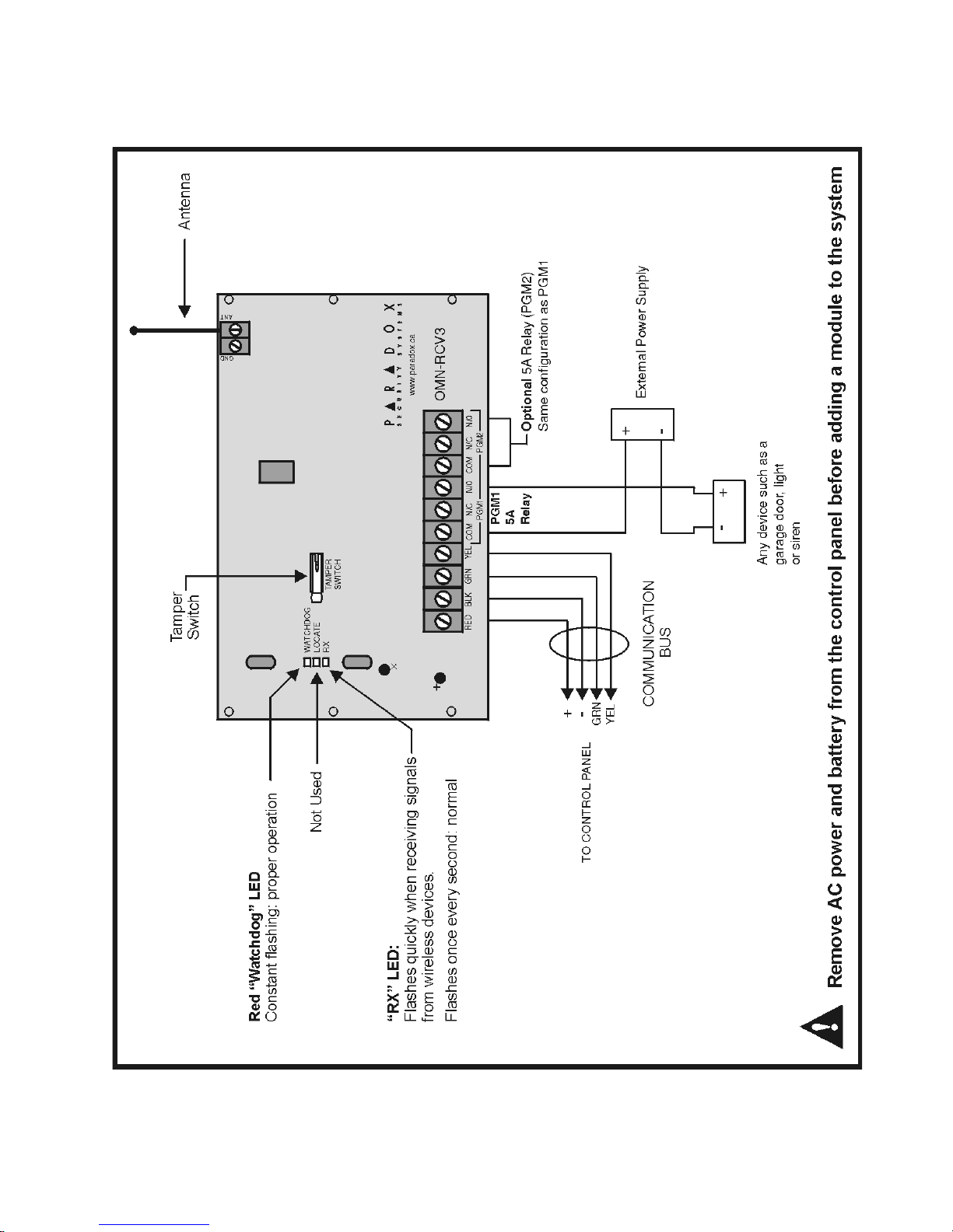
Figure 2.1: Connecting the OMN-RCV3 to the control panel
Omnia 5
Page 8

3.0 PROGR A MMI N G
To successfully install an Omnia wireless system to your Spectra system, ensure
that the following step s are com pl eted:
1. Install the Omnia Receiver. Connect the Omnia Receiver to the Spectra control
panel and power up.
2. Ass ign the remote controls if necessary.
3. Assign the transmitters (door contacts and motion detectors), and program their
zones.
4. Install the transmitters. Insert the batteries, and close the transmitter cover.
5. Wait for the control panel to be in “ready” mode. The status light on the keypad
will be green when the control panel is ready.
6. In order to ensure proper synchronization between the transmitters and receiver,
open and close the transmitters’ covers and zones.
3.1 HOW TO ENTER PROGRAMMING MODE
Programming of the OMN-RCV3 is done in Programming Mode through any keypad
connected to the Spectra control panel.
How to enter programming mode.
1. Press the [
2. Enter your [
3. Enter the [
ENTER
INSTALLER CODE
SECTION NUMBER] you wish to program.
4. Enter the required [
] button.
DATA
] (default = 000000).
].
The OMN-RCV3’s programming guide can be found in the appropriate
Spectra Programming Guide.
3.2 WIRELESS TRANSMITTER PROGRAMMING
The programming of the wireless transmitters (detectors and door contacts) is
accomplished in two steps:
1. Assigning the detectors and door contacts to the Wireless Receiver Module.
2. Programming the zones in the Spectra control panel.
6 Reference & Installation Manual
Page 9
3.2.1 A
SSIGNING DETECTORS AND DOOR CONTACTS TO THE RECEIVER
SECTIONS
[601] TO [608]
In Spectra systems, up to 8 wireless transmitters (detectors and door
contacts) can be assigned to each Receiver Module. Section [601] to [608]
represent expansion inputs 1 to 8 respectively. For example, section [601] is
assigned to ex pan si on in pu t 1, section [602] is assigned to expan sion input 2,
etc. (refer to Table 3.1). Each Expansion Input represents a specific zone in
the system depending on the type of Spectra control panel being used and
whether the ATZ option is enabled (refer to the appropriate Spectra control
panel Programming Guide).
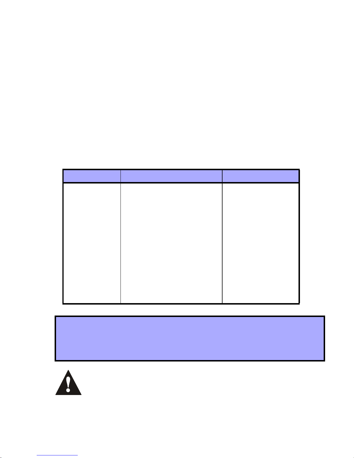
Table 3.1: Sections and Expansion Inputs
Section # 6-digit Serial Number Expansion Input
[601]
[602]
[603]
___/___/___/___/___/___ Input 1
___/___/___/___/___/___ Input 2
___/___/___/___/___/___ Input 3
[604]
[605]
[606]
[607]
[608]
___/___/___/___/___/___ Input 4
___/___/___/___/___/___ Input 5
___/___/___/___/___/___ Input 6
___/___/___/___/___/___ Input 7
___/___/___/___/___/___ Input 8
How to assign detectors & door contacts to the receiver module.
In step 3 in section 3.1 on page 6:
1. Enter the desired [
SECTION NUMBER
] (601 to 608).
2. Enter the 6-digit serial number of the detector or door contact.
Do not assi gn dete ction de vices from dif ferent module s to the same
expansion inpu t. For exampl e, do not assig n a wir eless transm itt er
to sectio n [601], t hen conn ect a det ection de vice to i nput Z1 of the
APR3-ZX8.
Omnia 7
Page 10

The serial nu mb er is loc at ed on the in sid e o f the tran smi t te r or you
can use the Unknown Serial Number Display method (refer to
section 3.4 on page 10) to determine its serial number.
The transmi tters must be ac tivated once h aving been assi gned to
the Receiver. T o activate a transmitter, insert the batteries and close
the cover. To ensure proper synchronizati on between the receiver
and the tr ansmitte r, open and close t he zone correspon ding t o the
transmit te r.
3.2.2 D
ELETING THE DETECTORS AND DOOR CONTACTS
SECTIONS
[601] TO [608]
How to delete the assigned transmitters.
In step 3 in section 3.1 on page 6:
3.2.3 P
1. Enter the desired [
2. Press the [
ROGRAMMING THE ZONES IN THE SPECTRA CONTROL PANEL
FORCE
SECTION NUMBER
] button six times to clear the serial number.
] (601 to 608).
The zones allocated to the wireless transmitters must be programmed in the
Spectra control panel. Refer to the appropriate Spectra Reference &
Installation Manual for instructions on programming the zones.
3.3 VIEWING THE TRANSMITTER SIGNAL STRENGTH
SECTIONS
[631] TO [638]
Once the detectors and/or door contacts have been installed and assigned to the
Receiver Module, the signal strength of each transmitter can be verified in sections
[631] to [638]. Each section represents the signal strength viewer for a specific
device. For example, section [631] is the viewer for the device in section [601] and
section [638] is the viewer for the device in section [608]. Please note that this
feature will only work with wireless transmitters that have already been assigned to
an Expansion I npu t (zon e) as desc rib ed in section 3.2.1 on pag e 7. A read ing of 1 is
the weakest and a reading of 8 is the strongest. An average reading of 3 and up is
8 Reference & Installation Manual
Page 11
acceptable. Sometimes moving the transmitter or receiver by a small amount will
greatly increase the signal reception.
How to view a transmitter’s signal strength.
In step 3 in section 3.1 on page 6:
1. Enter the desired [
SECTION NUMBER
] (631 to 638).
2. Press the transmitter’s tamper switch, or open the corresponding zone.
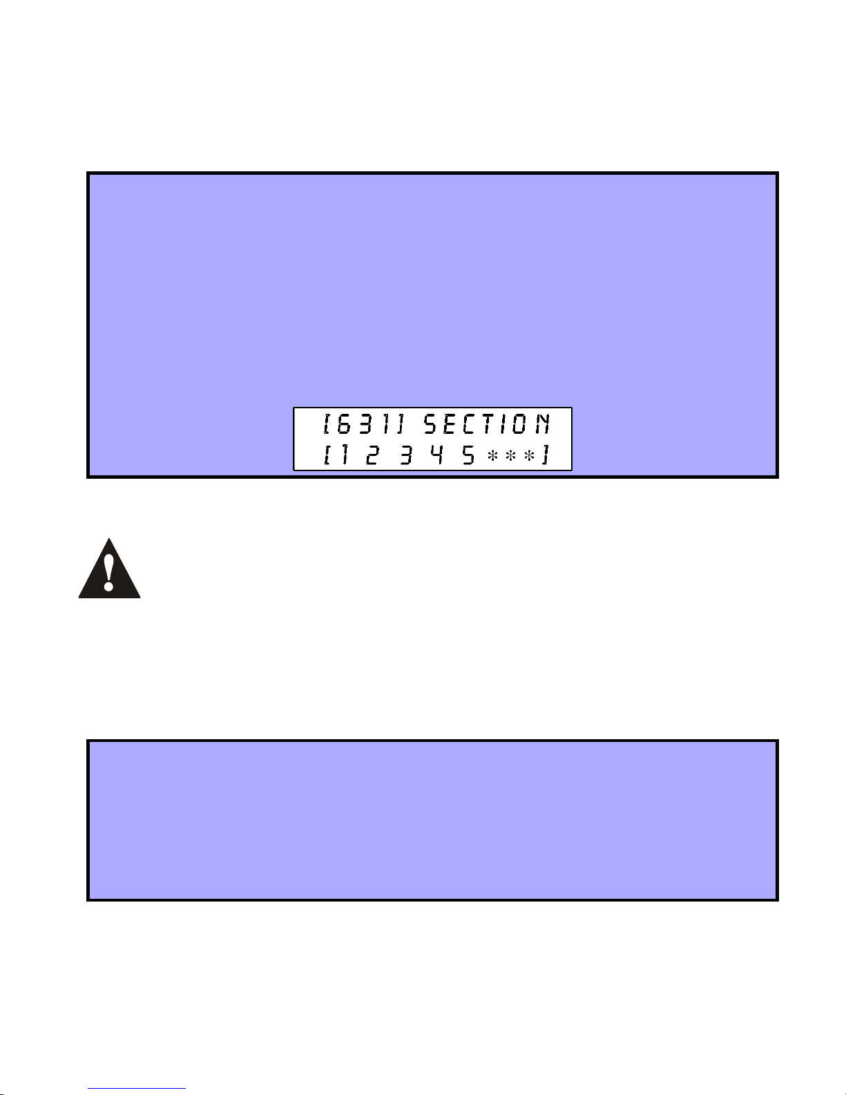
On an LED keypad: The keypad will illuminate numbers 1 to 8.
On an LCD keypad: The keypad will display from 1 to 8 characters on the
screen. For example, in the figure below the LCD screen shows a signal
strength reading of 5.
After entering the desired section, ignore the first reading as it will not be
accurate.
You can also use the OMN-RCV3’s beep sequence feature to verify a transmitter’s
signal strength. When you press a transmitter’s tamper switch, beep tones
emanating from all the keypads connected to the communicatio n bu s will advise yo u
of the transmitter’s signal strength.
How to attain a transmitter’s signal strength using the beep sequence.
1. Press the transmitter’s tamper switch.
2. Listen for the beep tones:
If the signal strength is less than 3 = One beep
If the signal strength is between 3 and 6 = Two beeps
If the signal strength is greater than 6 = Three beeps
Omnia 9
Page 12

3.4 VIEWING UNKNOWN SERIAL NUMBERS
S
ECTION
[630]
This feature will display the serial number of any Omnia motion detector or door
contact on any Spectra keypad.
How to view unknown transmitter serial numbers.
In step 3 in section 3.1 on page 6:
1. Enter section [630].
2. Press the tamper switch of any Omnia wireless motion detector or door
contact. When the signal has been received, the keypad will emit a
confirmation beep (“Beep-Beep-Beep-Beep-Beep”).
3. On an LED Keypad: The serial number digits will appear one at a time by
illuminating the corresponding LED light. To view the next digit press the
ENTER
[
] button.
On an LCD K eyp ad: T he f irs t 3 d igi ts of th e s eri al n um ber will appear. Press
the [
ENTER
] button 3 times to view the next 3 digits.
3.5 SYSTEM RESET
Refer to the appropriate Spectra Reference and Installation Manual.
4.0 SUPERVISION OPTIONS
4.1 CHECK-IN SUPERVISION
S
ECTION
Option [1] enables the Check-in Supervision feature. The Wireless Receiver Module
waits for each of its assigned detectors and/or door contacts to send a status signal
within a specified time period (as programmed in section 4.2) to confirm their
presence and functionality. If a device has not sent a signal within that time period,
the Wireless Receiver Module will transmit a supervision loss signal to the control
panel. The control panel can then generate a trouble, an alarm, and/or can transmit
[610]: O
PTION
[1]
10 Reference & Installation Manual
Page 13

a report code to the monitoring station. For details refer to the appropriate Spectra
Reference & Ins tallation Manual.
How to enable check-in supervision.
In step 3 in section 3.1 on page 6:
1. Enter section [610].
2. Enable or disable option [1].
Option [1] OFF = Check-In Supervision disabled (default)
Option [1] ON = Check-In Supervision enabled
4.2 CHECK-IN SUPERVISION TIMER SETTINGS
S
ECTION
[610]: O
PTIONS
[2]
AND
[5]
Options [2] and [5] define the time period that must elapse before the Omnia
transmitters send a status signal to the Wireless Receiver Module. For example, if
the timer is set to 12 min (option [5]=off ; option [2]=on), the transmitters will send a
status signal every 12 minutes to the Receiver Module. If the OMN-RCV3 does not
receive a s ignal from one of its w ireles s trans mitters w ithi n the pe riod de fined h ere, it
can send a Supervision Loss signal to the control panel. Refer to section 4.1 for
instructio ns on ena bli ng check-in supervision.
How to set the check-in supervision timer.
In step 3 in section 3.1 on page 6:
1. Enter section [610].
2. Enable or disable options [2] & [5].
Option [2] OFF = hours (default)
Option [2] ON = minutes
Option [5] OFF = 12 (default)
Option [5] ON = 6
The assigned transmitters must be set to the same Check-In timer setting
as the Re ceiver. For exa mple, if the R eceiver Check-I n timer is set at 12
hours, the transmitters’ Check-In timers must also be 12 hours.
Omnia 11
Page 14

4.3 LOW BATTERY SUPERVISION
When the battery voltage of an Omnia wireless transmitter (motion detector or door
contact ) drops to les s than 3.1V, the Sp ectra contr ol panel will s end a low batt ery
report code to the monitoring station, and a trouble will appear in the keypad’s
trouble display.
4.4 ON-BOARD MODULE TAMPER SUPERVISION ZONE ASSIGNMENT
S
ECTION
[615]:
The OMN-RCV3 comes equipped with an on-board tamper switch. This feature will
allow a module tamper to report through one of the module’s Expansion Inputs
(zone). When a tamper is detected on the module, it will send a Zone Tamper report
code to the control panel via the communication bus. The Zone Tamper report code
will originate from the zone defined by the Expansion Input (001-008) you have
programmed in section [615]. Please note that the corresponding zone must be
programmed (refer to the appropriate Spectra Reference & Installation Manual for
more details).
For example, when you program 003 (Expansion Input 3) in section [615] of a
Spectra 1728 panel wi th the ATZ feature enabled, and a tampe r occu rs on the OMNRCV3 module, the control panel will transmit the Zone Tamper report code as
originating from zone 15.
If you En able t he OMN-R CV 3’s t amp er s wit ch in se cti on [6 15 ], the ta mp er
switch will occupy one of the zones.
How to assign the Receiver’s tamper switch to a zone.
In step 3 in section 3.1 on page 6:
1. Enter section [615].
2. Enter an [
INPUT NUMBER
000=Disabled (default)
12 Reference & Installation Manual
] (001-008).
Page 15

5.0 PROGRAMMABLE OUTPUTS (PGMs)
5.1 PGM ACTIVATION
The Omnia Wireless Receiver Module comes equipped with one on-board 5A PGM
relay output (programmable output). A second 5A PGM output is available as an
option. PGM1 and PGM2 are always enabled and are activated only through the
Omnia Remote Control (OMN-RCT1). Remote control button 1 (C) controls PGM1,
and button 2 (D) c ontrols PGM2 (refer to Fig ure 6.4 on page 1 8 fo r b utto n l ocati ons ).
Press the appropriate remote control button to activate the corresponding PGM. If
the PGM deactivation mode is set at “Manually” (refer to section 5.2), the button
used to activate the PGM will also be used to deactivate the PGM.
5.2 PGM DEACTIVATION
SECTION
[610] :
OPTIONS
[6]
AND
[7]
Once a PGM has been activated (refer to sec tio n 5.1), optio ns [6] and [7] determine
how the respective PGM will deactivate. If the option is OFF, the activated PGM will
automatically deactivate after 2 seconds. If the option is ON, the activated PGM can
only be deactivated by pressing the appropriate button on the Omnia Remote
Control (refer to section 5.1).
How to set the PGM deactivation mode.
In step 3 in section 3.1 on page 6:
1. Enter section [610].
2. Enable or disable options [6] and [7].
Option [6] OFF = PGM1: 2 second timer (default)
Option [6] ON = PGM1: Manually
Option [7] OFF = PGM2: 2 second timer (default)
Option [7] ON = PGM2: Manually
Omnia 13
Page 16

6.0 REMOTE CONTROL PROGRAMMING
The Omnia Wireless Receiver Module accepts up to eight fully programmable
remote controls. Programming the remote controls is accomplished in three steps:
1. The remote controls must be assigned to the Wireless Receiver Module.
2. The remote controls from the Wireless Receiver Module must be assigned to
User Access Codes.
3. The buttons on the remote controls must be programmed.
In Spectra systems, sections [721]/[731] to [728]/[738], [701] to [708], and [711] to
[718] are all interrelated. For example, when assigning a remote control to the
Receiver Module:
1. The remote control is assigned using the Automatic Learning method in sections
[721]/[731] to [728]/[738].
2. The remote control is assigned to User Access Codes in sections [701] to [708].
3. The remote control’s buttons are programmed in sections [71 1] to [718].
The remote control will transmit a signal for only 1 second when a button is
pressed. This is done to conserve the remote control’s batteries.
6.1 ASSIGNING A REMOTE CONTROL TO THE RECEIVER MODULE
S
ECTIONS
Remote controls are assigned to the module using the Automatic Learning method.
Depending on which Spectra system version you are using, the automatic learning
method dif fers .
For installations using a Spectra control panel version 1.23 or lower:
How to assign a remote control to the receiver module (V1.23 and lower).
In step 3 in section 3.1 on page 6:
1. Enter the desired [
2. Enter [111111]. A rejection beep will sound, and it will exit the section.
3. Press any button on the remote control twice, or until you hear three
[721] / [731] TO [728] / [738]
SECTION NUMBER
] (721 to 728).
consecutive rejection beeps (“Beeeeeeeeeeeeeeep”).
14 Reference & Installation Manual
Page 17
For installations using a Spectra control panel version 2.0 or higher:
How to assign a remote control to the receiver module (V2.0 and higher).
In step 3 in section 3.1 on page 6:
1. Enter desired [
SECTION NUMBER] (731 to 738).
2. Press any button on the remote control twice, or until the confirmation beep
sounds (“Beep-Beep-Beep-Beep-Beep”).
If you are having trouble assigning the remote control, the environment
may be to o noisy. Therefore, we recommend that you assign the remote
controls bef ore i nstall ing t he d et ector s an d do or co ntac ts.
6.2 ASSIGNING THE REMOTE CONTROLS TO USER ACCESS CODES
S
ECTIONS
Each remote control must be assigned to a User Access Code. All User Access Codes
are given a User Number from 001 to 048. Enter the desir ed User Nu mber in a secti on
from [701] to [708] that represent the remote control assigned in sections [721]/[731] to
[728]/[738] (refer to section 6.1 on page 14). For example, the remote control assigned
in section [731] will be assigned to the User Access Code designated in section [701].
[701] TO [708]:
How to assign a remote control to a user access code.
In step 3 in section 3.1 on page 6:
1. Enter the desired [
SECTION NUMBER
] (701 to 708).
2. Enter the User Number to be assigned to the remote control (001 to 048).
6.3 P ROGRAMMING THE REMOTE CONTROL BUTTONS
S
ECTIONS
Each remote control can be programmed to send a signal to the control panel to perform
up to 8 different actions. Each digit in sections [711] to [718] represents a button or
combination of buttons (refer to Table 6.1 on page 16). When a user arms or disarms
using the remote control, the contr ol panel will arm or disa rm all the ar eas assigned t o
the User Access Code. For example, you arm with a remote control whose User Access
Code is assigned to areas 1 and 2, the control panel will attempt to arm areas 1 and 2.
[711] TO [718]
Omnia 15
Page 18

Sections [711] to [718] represent the remote controls assigned to sections [721]/
[731] to [728]/[738] (refer to section 6.1 on page 14). For example, the buttons for
the remote control assigned in section [731] will be programmed in sec tion [711].
How to program the remote control buttons:
In step 3 in section 3.1 on page 6:
1. Enter the desired [
SECTION NUMBER
] (711 to 718).
2. Enter the hexade cima l value (0 to D) o f the des ired opti ons from Table 6.2 on
page 17 in the appropriate space (refer to Table 6.1 on page 16). If you do
not wish to program all the buttons or button combinations, simply press the
ENTER
[
] button at any time to save and exit.
Note: To delete the hexadecimal values in a particular section (711-718),
press the [
FORCE
] button once for every value.
Table 6.1: Remote Control Button Programming
Remote Control Button Programming (refer to Table 6.2)
Section
[711] ____/____/____/____/____/____/____/____
A B C D A+B C+D A+C B+D
[712] ____/____/____/____/____/____/____/____
A B C D A+B C+D A+C B+D
remote control #1
remote control #2
[713] ____/____/____/____/____/____/____/____
A B C D A+B C+D A+C B+D
[714] ____/____/____/____/____/____/____/____
A B C D A+B C+D A+C B+D
[715] ____/____/____/____/____/____/____/____
A B C D A+B C+D A+C B+D
[716] ____/____/____/____/____/____/____/____
A B C D A+B C+D A+C B+D
[717] ____/____/____/____/____/____/____/____
A B C D A+B C+D A+C B+D
[718] ____/____/____/____/____/____/____/____
A B C D A+B C+D A+C B+D
16 Reference & Installation Manual
remote control #3
remote control #4
remote control #5
remote control #6
remote control #7
remote control #8
Page 19

Table 6.2: Button Options
[FORCE
] = Button Disabled [7] = Regular Arm and Disarm
[1] = Regular Arm [8] = Generate a Panic 1 Alarm (Police)
[2] = Stay Arm [9] = Generate a Panic 2 Alarm (Medical)
[3] = Instant Arm [A] = Generate a Panic 3 Alarm (Fire)
[4] = Force Arm [B] = Activates any PGMs that have Event Group
#07 as their Activation Event
[5] = Disarm [C] = Activates any PGMs that have Event Group
#08 as their Activation Event
[6] = Disarm when there is
no alarm
[D] = Activates any PGMs that have Event Group
#09 as their Activation Event
Table 6.3: Decimal & Hexadecimal Programming Table
What Do I
What Do I See?
Value or Action
Press?
10-Zone LED 16-Zone LED LCD
Values 1 to 9 [1] to [9] [1] to [9] [1] to [9] [1] to [9]
A (hex a only) [0] [0 (10)] [10] 0
B (hex a only) [
C (hexa only) [
STAY
BYP
D (hexa only) [MEM
E (hex a only) [
F (hexa only) [PG] / [
Exit Without
TBL
[CLEAR
] / [
FNC
Saving
Insert Blank
[
FORCE
][
][
][
][
TRBL
1] [PG][15] F
][
ENTER
flashes
] Displays next digit or next section
][11] B
STAY
][12] C
BYP
][13] D
MEM
][14] E
TBL
]
[
ARM
[STAY
1] &
1] flash
“SECTION [ ]”
Digit
Save Data [
ENTER
] Advances to the next section
Omnia 17
Page 20
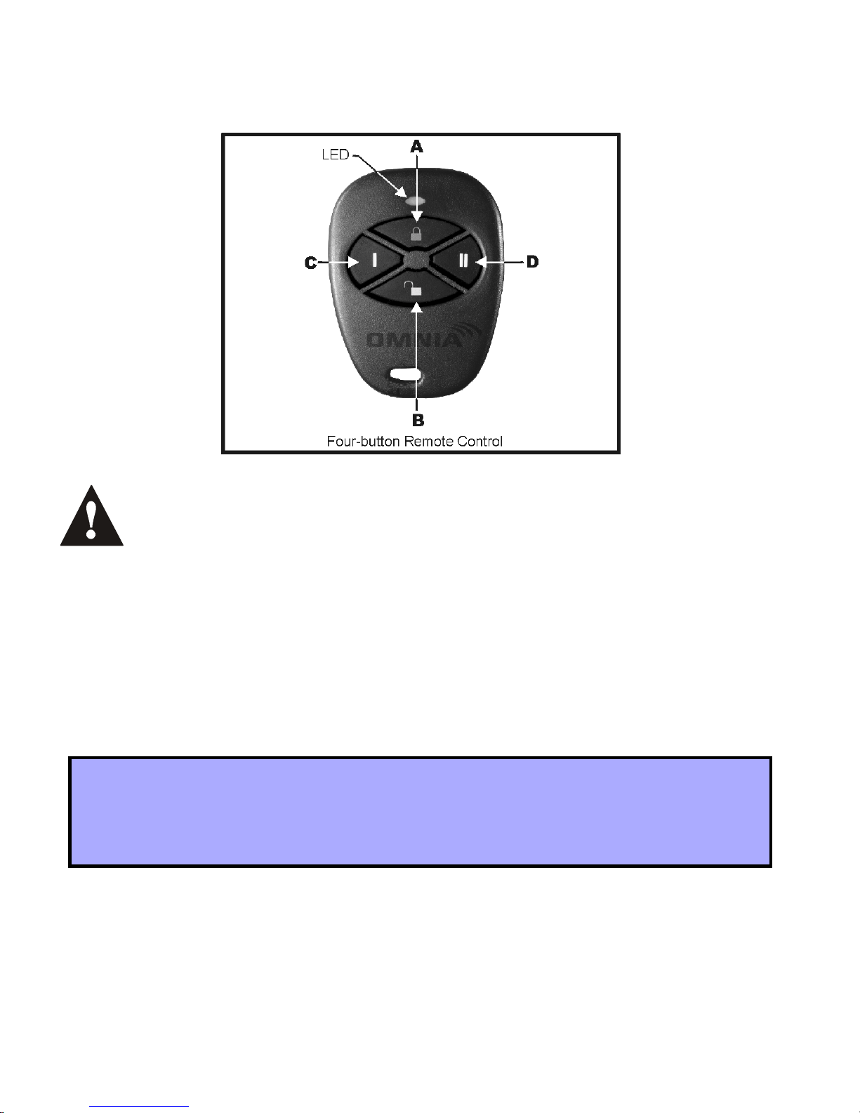
Figure 6.4: Remote Control Button Identification
The User Code assigned to the remote control (refer to section 6.2 on page
15) must have the same User Options enabled. For example, if you enable
the Force A rming button opt ion, you must enab le the appropri ate Force
Arming user option. Also, if you enable any Panic button options, you
must enable the Panic options in the Spectra control panel (refer to the
appropriate Spectra Reference & Installation Manual).
6.4 DELETING REMOTE CONTROLS
S
ECTIONS
For installations using a Spectra control panel version 1.23 or lower:
How to delete a remote control (Spectra version 1.23 or lower):
In step 3 in section 3.1 on page 6:
1. Enter the desired [
2. Enter [000000].
[721]/[731] TO [728]/[738]
SECTION NUMBER
] (721 to 728).
18 Reference & Installation Manual
Page 21
For installations using a Spectra control panel version 2.0 or higher:
How to delete a remote control (Spectra version 2.0 or higher):
In step 3 in section 3.1 on page 6:
1. Enter the desired [
2. Press the [
FORCE
] button.
SECTION NUMBER
] (731 to 738).
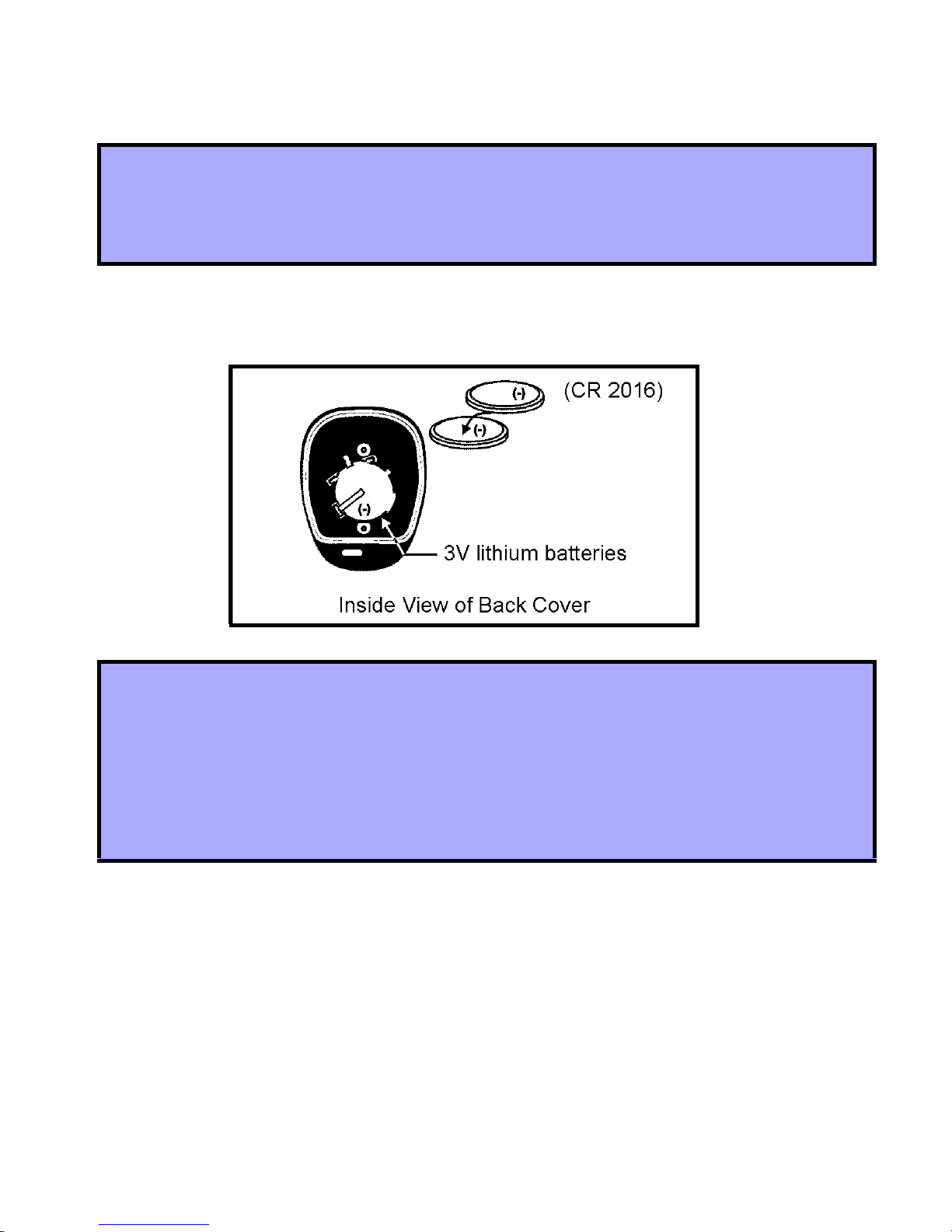
6.5 REPLACING THE REMOTE CONTROL BATTERIES
How to replace the remote control batteries.
1. Remove the two screws from the back of the remote control and remove the
back cover.
2. Remove the old batteries from inside the remote control.
3. Replace with tw o 3 V li thi um ba tteries (CR2016 ) en su ring proper polarity. The
positive of the batteries is inserted face down.
4. Set the back cover in place, and fasten it with the two screws.
Omnia 19
Page 22

7.0 LIST OF SECTIONS
Section Description
[601] to [608] - Assign detectors an d door contacts to the receiver
- Delete the detectors and door contacts
[610] Option [1]: Check-in supervision
Option [2]: Check-in supervision base time
Option [5]: Check-in supervision time value
Option [6]: PGM1 deactivation mode
Option [7]: PGM2 deactivation mode
[615] On-board module tamper supervision zone assignment
[630] View unknown serial numbers
[631] to [638] View the detector and door contact signal strengths
[701] to [708] Assign the remote controls to user access codes
[711] to [718] Programming the remote control buttons
- Assign a remote control to the receiver
[721] to [728]
[731] to [738]
For Spectra versions 1.23 or lower
For Spectra versions 2.0 or higher
- Delete a remote control
20 Reference & Installation Manual
Page 23

WARRANTY
The Seller warrants its products to be free from defects in materials and
workmanship under normal use for a period of one year. Except as specifically
stated herein, all express or implied warranties whatsoever, statutory or otherwise,
including without limitation, any implied warranty of merchantability and fitness for a
particular purpose, are expressly excluded. Because Seller does not install or
connect the products and because the products may be used in conjunction with
products not manufactured by Seller, Seller cannot guarantee the performance of
the security system. Seller obligation and liability under this warranty is expressly
limited to repairing or replacing, at Seller's option, any product not meeting the
specifications. In no event shall the Seller be liable to the buyer or any other person
for any loss or damages whether direct or indirect or consequential or incidental,
including without limitation, any damages for lost profits, stolen goods or claims by
any other party caused by defective goods or otherwise arising from the improper,
incorrect or otherwise faulty installation or use of the merchandise sold.
Omnia 21
Page 24

NOTES
Page 25

Page 26

Page 27

Page 28

 Loading...