

Page 1

748P-EI01
Page 2

Page 3

Table of Contents
TABLE OF CONTENTS
INTRODUCTION . . . . . . . . . . . . . . . . . . . . . . . . . . . . . . . . . . . . . . . . . . . . . . . . . . . . . . . . . . . . . . . . . . . . . . . . . . . . . . . . . 1
1.1 About This Manual . . . . . . . . . . . . . . . . . . . . . . . . . . . . . . . . . . . . . . . . . . . . . . . . . . . . . . . . . . . . . . . . . . . . . . . . . . . 1
1.2 Features . . . . . . . . . . . . . . . . . . . . . . . . . . . . . . . . . . . . . . . . . . . . . . . . . . . . . . . . . . . . . . . . . . . . . . . . . . . . . . . . . . . 1
1.3 Specifications . . . . . . . . . . . . . . . . . . . . . . . . . . . . . . . . . . . . . . . . . . . . . . . . . . . . . . . . . . . . . . . . . . . . . . . . . . . . . . . 2
1.4 Accessories & Keypads . . . . . . . . . . . . . . . . . . . . . . . . . . . . . . . . . . . . . . . . . . . . . . . . . . . . . . . . . . . . . . . . . . . . . . . 2
1.5 About Paradox . . . . . . . . . . . . . . . . . . . . . . . . . . . . . . . . . . . . . . . . . . . . . . . . . . . . . . . . . . . . . . . . . . . . . . . . . . . . . . 2
INSTALLATION . . . . . . . . . . . . . . . . . . . . . . . . . . . . . . . . . . . . . . . . . . . . . . . . . . . . . . . . . . . . . . . . . . . . . . . . . . . . . . . . . . 3
2.1 Location & Mounting . . . . . . . . . . . . . . . . . . . . . . . . . . . . . . . . . . . . . . . . . . . . . . . . . . . . . . . . . . . . . . . . . . . . . . . . . 3
2.2 Earth Ground . . . . . . . . . . . . . . . . . . . . . . . . . . . . . . . . . . . . . . . . . . . . . . . . . . . . . . . . . . . . . . . . . . . . . . . . . . . . . . . 3
2.3 Power . . . . . . . . . . . . . . . . . . . . . . . . . . . . . . . . . . . . . . . . . . . . . . . . . . . . . . . . . . . . . . . . . . . . . . . . . . . . . . . . . . . . . 3
2.4 Telephone Line Connection . . . . . . . . . . . . . . . . . . . . . . . . . . . . . . . . . . . . . . . . . . . . . . . . . . . . . . . . . . . . . . . . . . . . 4
2.5 Bell/Siren Output . . . . . . . . . . . . . . . . . . . . . . . . . . . . . . . . . . . . . . . . . . . . . . . . . . . . . . . . . . . . . . . . . . . . . . . . . . . . 5
2.6 Programmable Outputs (PGM) . . . . . . . . . . . . . . . . . . . . . . . . . . . . . . . . . . . . . . . . . . . . . . . . . . . . . . . . . . . . . . . . . 5
2.7 Keypad & Keyswitch Connections . . . . . . . . . . . . . . . . . . . . . . . . . . . . . . . . . . . . . . . . . . . . . . . . . . . . . . . . . . . . . . . 5
2.8 Keypad Zone Connections . . . . . . . . . . . . . . . . . . . . . . . . . . . . . . . . . . . . . . . . . . . . . . . . . . . . . . . . . . . . . . . . . . . . . 5
2.9 Single Zone Input Terminal Connections . . . . . . . . . . . . . . . . . . . . . . . . . . . . . . . . . . . . . . . . . . . . . . . . . . . . . . . . . . 7
2.10 Advanced Technology Zone (ATZ) Connections . . . . . . . . . . . . . . . . . . . . . . . . . . . . . . . . . . . . . . . . . . . . . . . . . . . . 9
2.11 Fire Circuit . . . . . . . . . . . . . . . . . . . . . . . . . . . . . . . . . . . . . . . . . . . . . . . . . . . . . . . . . . . . . . . . . . . . . . . . . . . . . . . . 10
2.12 Serial Output Connector . . . . . . . . . . . . . . . . . . . . . . . . . . . . . . . . . . . . . . . . . . . . . . . . . . . . . . . . . . . . . . . . . . . . . . 11
ACCESS CODES . . . . . . . . . . . . . . . . . . . . . . . . . . . . . . . . . . . . . . . . . . . . . . . . . . . . . . . . . . . . . . . . . . . . . . . . . . . . . . . . 12
3.1 Installer Code . . . . . . . . . . . . . . . . . . . . . . . . . . . . . . . . . . . . . . . . . . . . . . . . . . . . . . . . . . . . . . . . . . . . . . . . . . . . . . 12
3.2 Master & User Codes . . . . . . . . . . . . . . . . . . . . . . . . . . . . . . . . . . . . . . . . . . . . . . . . . . . . . . . . . . . . . . . . . . . . . . . . 12
3.3 User / Access Code Length . . . . . . . . . . . . . . . . . . . . . . . . . . . . . . . . . . . . . . . . . . . . . . . . . . . . . . . . . . . . . . . . . . . 12
3.4 Duress . . . . . . . . . . . . . . . . . . . . . . . . . . . . . . . . . . . . . . . . . . . . . . . . . . . . . . . . . . . . . . . . . . . . . . . . . . . . . . . . . . . 12
3.5 Installer Lock . . . . . . . . . . . . . . . . . . . . . . . . . . . . . . . . . . . . . . . . . . . . . . . . . . . . . . . . . . . . . . . . . . . . . . . . . . . . . . 12
PROGRAMMING METHODS . . . . . . . . . . . . . . . . . . . . . . . . . . . . . . . . . . . . . . . . . . . . . . . . . . . . . . . . . . . . . . . . . . . . . 13
4.1 Espload Software . . . . . . . . . . . . . . . . . . . . . . . . . . . . . . . . . . . . . . . . . . . . . . . . . . . . . . . . . . . . . . . . . . . . . . . . . . . 13
4.2 Keypad . . . . . . . . . . . . . . . . . . . . . . . . . . . . . . . . . . . . . . . . . . . . . . . . . . . . . . . . . . . . . . . . . . . . . . . . . . . . . . . . . . . 13
PANEL SETTINGS FOR ESPLOAD . . . . . . . . . . . . . . . . . . . . . . . . . . . . . . . . . . . . . . . . . . . . . . . . . . . . . . . . . . . . . . 16
5.1 Panel Answer Options . . . . . . . . . . . . . . . . . . . . . . . . . . . . . . . . . . . . . . . . . . . . . . . . . . . . . . . . . . . . . . . . . . . . . . . 16
5.2 Panel Identifier . . . . . . . . . . . . . . . . . . . . . . . . . . . . . . . . . . . . . . . . . . . . . . . . . . . . . . . . . . . . . . . . . . . . . . . . . . . . . 17
5.3 PC Password . . . . . . . . . . . . . . . . . . . . . . . . . . . . . . . . . . . . . . . . . . . . . . . . . . . . . . . . . . . . . . . . . . . . . . . . . . . . . . 17
5.4 Computer Telephone Number . . . . . . . . . . . . . . . . . . . . . . . . . . . . . . . . . . . . . . . . . . . . . . . . . . . . . . . . . . . . . . . . . 17
5.5 Call Espload . . . . . . . . . . . . . . . . . . . . . . . . . . . . . . . . . . . . . . . . . . . . . . . . . . . . . . . . . . . . . . . . . . . . . . . . . . . . . . . 17
5.6 Answer Espload . . . . . . . . . . . . . . . . . . . . . . . . . . . . . . . . . . . . . . . . . . . . . . . . . . . . . . . . . . . . . . . . . . . . . . . . . . . . 17
5.7 Cancel Communication . . . . . . . . . . . . . . . . . . . . . . . . . . . . . . . . . . . . . . . . . . . . . . . . . . . . . . . . . . . . . . . . . . . . . . 18
5.8 Call Back . . . . . . . . . . . . . . . . . . . . . . . . . . . . . . . . . . . . . . . . . . . . . . . . . . . . . . . . . . . . . . . . . . . . . . . . . . . . . . . . . 18
5.9 Automatic Event Buffer Transmission . . . . . . . . . . . . . . . . . . . . . . . . . . . . . . . . . . . . . . . . . . . . . . . . . . . . . . . . . . . 18
EVENT REPORTING . . . . . . . . . . . . . . . . . . . . . . . . . . . . . . . . . . . . . . . . . . . . . . . . . . . . . . . . . . . . . . . . . . . . . . . . . . . . 19
6.1 Reporting Options . . . . . . . . . . . . . . . . . . . . . . . . . . . . . . . . . . . . . . . . . . . . . . . . . . . . . . . . . . . . . . . . . . . . . . . . . . 20
6.2 Central Station Telephone Number 1 . . . . . . . . . . . . . . . . . . . . . . . . . . . . . . . . . . . . . . . . . . . . . . . . . . . . . . . . . . . . 21
6.3 Central Station Telephone Number 2 . . . . . . . . . . . . . . . . . . . . . . . . . . . . . . . . . . . . . . . . . . . . . . . . . . . . . . . . . . . . 22
6.4 System Account Codes . . . . . . . . . . . . . . . . . . . . . . . . . . . . . . . . . . . . . . . . . . . . . . . . . . . . . . . . . . . . . . . . . . . . . . 22
6.5 Communicator Formats . . . . . . . . . . . . . . . . . . . . . . . . . . . . . . . . . . . . . . . . . . . . . . . . . . . . . . . . . . . . . . . . . . . . . . 22
6.6 Reporting Event Codes . . . . . . . . . . . . . . . . . . . . . . . . . . . . . . . . . . . . . . . . . . . . . . . . . . . . . . . . . . . . . . . . . . . . . . 24
6.7 Auto Test Report . . . . . . . . . . . . . . . . . . . . . . . . . . . . . . . . . . . . . . . . . . . . . . . . . . . . . . . . . . . . . . . . . . . . . . . . . . . 26
6.8 Manual Test Report . . . . . . . . . . . . . . . . . . . . . . . . . . . . . . . . . . . . . . . . . . . . . . . . . . . . . . . . . . . . . . . . . . . . . . . . . 26
6.9 Power Failure Report Delay . . . . . . . . . . . . . . . . . . . . . . . . . . . . . . . . . . . . . . . . . . . . . . . . . . . . . . . . . . . . . . . . . . . 26
6.10 Recent Close Delay . . . . . . . . . . . . . . . . . . . . . . . . . . . . . . . . . . . . . . . . . . . . . . . . . . . . . . . . . . . . . . . . . . . . . . . . . 26
6.11 Report Zone Restore Options . . . . . . . . . . . . . . . . . . . . . . . . . . . . . . . . . . . . . . . . . . . . . . . . . . . . . . . . . . . . . . . . . 27
6.12 Report Code Disarming Options . . . . . . . . . . . . . . . . . . . . . . . . . . . . . . . . . . . . . . . . . . . . . . . . . . . . . . . . . . . . . . . 27
ZONE DEFINITIONS . . . . . . . . . . . . . . . . . . . . . . . . . . . . . . . . . . . . . . . . . . . . . . . . . . . . . . . . . . . . . . . . . . . . . . . . . . . . 28
7.1 Zone Speed . . . . . . . . . . . . . . . . . . . . . . . . . . . . . . . . . . . . . . . . . . . . . . . . . . . . . . . . . . . . . . . . . . . . . . . . . . . . . . . 29
i
Page 4

Table of Contents
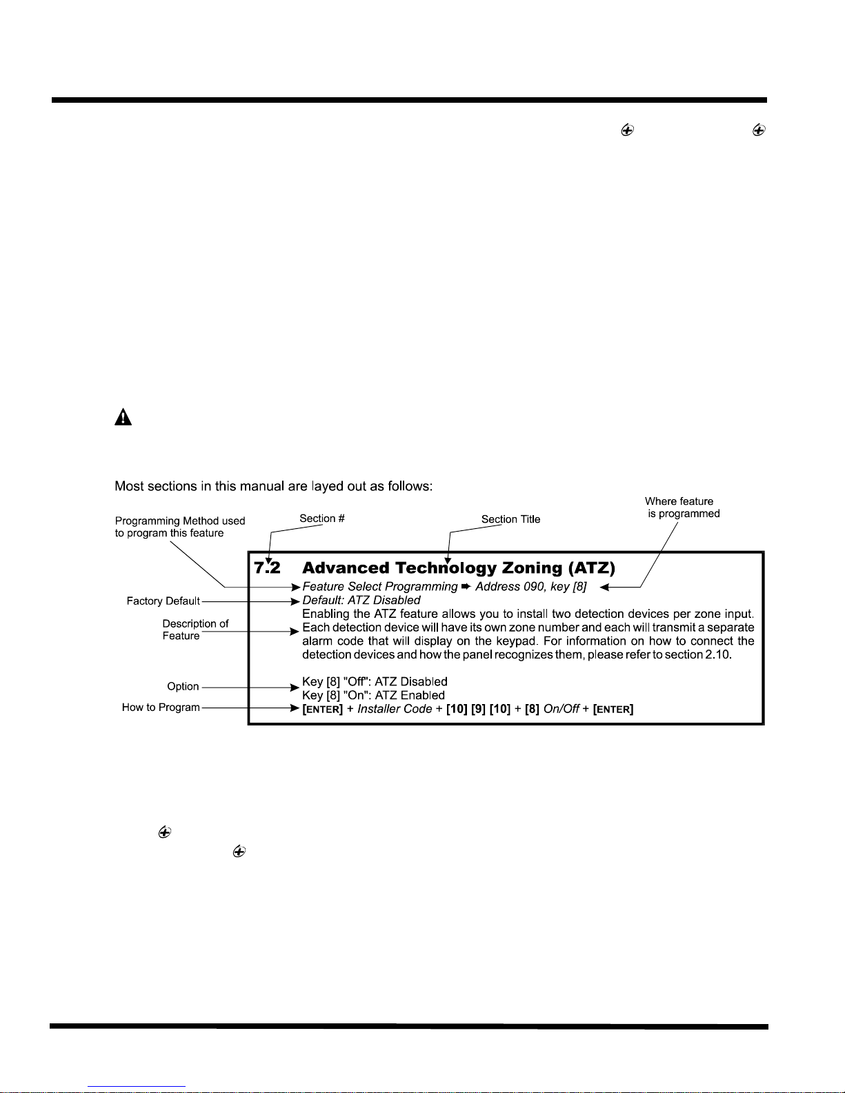
7.2 Advanced Technology Zoning (ATZ) . . . . . . . . . . . . . . . . . . . . . . . . . . . . . . . . . . . . . . . . . . . . . . . . . . . . . . . . . . . . 29
7.3 Intellizones . . . . . . . . . . . . . . . . . . . . . . . . . . . . . . . . . . . . . . . . . . . . . . . . . . . . . . . . . . . . . . . . . . . . . . . . . . . . . . . . 29
7.4 Silent Zones . . . . . . . . . . . . . . . . . . . . . . . . . . . . . . . . . . . . . . . . . . . . . . . . . . . . . . . . . . . . . . . . . . . . . . . . . . . . . . . 30
7.5 "24 Hour" & Fire Zones . . . . . . . . . . . . . . . . . . . . . . . . . . . . . . . . . . . . . . . . . . . . . . . . . . . . . . . . . . . . . . . . . . . . . . 30
7.6 Instant Zones . . . . . . . . . . . . . . . . . . . . . . . . . . . . . . . . . . . . . . . . . . . . . . . . . . . . . . . . . . . . . . . . . . . . . . . . . . . . . . 30
7.7 Follow Zones . . . . . . . . . . . . . . . . . . . . . . . . . . . . . . . . . . . . . . . . . . . . . . . . . . . . . . . . . . . . . . . . . . . . . . . . . . . . . . 30
7.8 Entry Delay 1 . . . . . . . . . . . . . . . . . . . . . . . . . . . . . . . . . . . . . . . . . . . . . . . . . . . . . . . . . . . . . . . . . . . . . . . . . . . . . . 31
7.9 Entry Delay 2 . . . . . . . . . . . . . . . . . . . . . . . . . . . . . . . . . . . . . . . . . . . . . . . . . . . . . . . . . . . . . . . . . . . . . . . . . . . . . . 31
7.10 Partitioning . . . . . . . . . . . . . . . . . . . . . . . . . . . . . . . . . . . . . . . . . . . . . . . . . . . . . . . . . . . . . . . . . . . . . . . . . . . . . . . . 31
7.11 Bypass Enabled Zones . . . . . . . . . . . . . . . . . . . . . . . . . . . . . . . . . . . . . . . . . . . . . . . . . . . . . . . . . . . . . . . . . . . . . . 32
7.12 EOL Zones (Enabled/Disabled) . . . . . . . . . . . . . . . . . . . . . . . . . . . . . . . . . . . . . . . . . . . . . . . . . . . . . . . . . . . . . . . . 32
7.13 Keypad Zone 1 Supervision . . . . . . . . . . . . . . . . . . . . . . . . . . . . . . . . . . . . . . . . . . . . . . . . . . . . . . . . . . . . . . . . . . . 33
7.14 Keypad Zone 2 Supervision . . . . . . . . . . . . . . . . . . . . . . . . . . . . . . . . . . . . . . . . . . . . . . . . . . . . . . . . . . . . . . . . . . . 33
ARM/DISARM & ALARM OPTIONS . . . . . . . . . . . . . . . . . . . . . . . . . . . . . . . . . . . . . . . . . . . . . . . . . . . . . . . . . . . . . . 34
8.1 "Timed" Auto Arming . . . . . . . . . . . . . . . . . . . . . . . . . . . . . . . . . . . . . . . . . . . . . . . . . . . . . . . . . . . . . . . . . . . . . . . . 35
8.2 "No Movement" Auto Arming . . . . . . . . . . . . . . . . . . . . . . . . . . . . . . . . . . . . . . . . . . . . . . . . . . . . . . . . . . . . . . . . . . 35
8.3 "One-Key" Regular Arming . . . . . . . . . . . . . . . . . . . . . . . . . . . . . . . . . . . . . . . . . . . . . . . . . . . . . . . . . . . . . . . . . . . 36
8.4 "One-Key" Stay/System A Arming . . . . . . . . . . . . . . . . . . . . . . . . . . . . . . . . . . . . . . . . . . . . . . . . . . . . . . . . . . . . . . 36
8.5 Arming using a keyswitch . . . . . . . . . . . . . . . . . . . . . . . . . . . . . . . . . . . . . . . . . . . . . . . . . . . . . . . . . . . . . . . . . . . . . 36
8.6 Bell Squawk . . . . . . . . . . . . . . . . . . . . . . . . . . . . . . . . . . . . . . . . . . . . . . . . . . . . . . . . . . . . . . . . . . . . . . . . . . . . . . . 36
8.7 Exit Delay . . . . . . . . . . . . . . . . . . . . . . . . . . . . . . . . . . . . . . . . . . . . . . . . . . . . . . . . . . . . . . . . . . . . . . . . . . . . . . . . . 37
8.8 Beep on Exit delay . . . . . . . . . . . . . . . . . . . . . . . . . . . . . . . . . . . . . . . . . . . . . . . . . . . . . . . . . . . . . . . . . . . . . . . . . . 37
8.9 Alarm Transmission Delay . . . . . . . . . . . . . . . . . . . . . . . . . . . . . . . . . . . . . . . . . . . . . . . . . . . . . . . . . . . . . . . . . . . . 37
8.10 Silent Zones & Silent Panics Option . . . . . . . . . . . . . . . . . . . . . . . . . . . . . . . . . . . . . . . . . . . . . . . . . . . . . . . . . . . . 37
8.11 Bell Cut-Off Time . . . . . . . . . . . . . . . . . . . . . . . . . . . . . . . . . . . . . . . . . . . . . . . . . . . . . . . . . . . . . . . . . . . . . . . . . . . 37
8.12 Code Priority . . . . . . . . . . . . . . . . . . . . . . . . . . . . . . . . . . . . . . . . . . . . . . . . . . . . . . . . . . . . . . . . . . . . . . . . . . . . . . 38
PGM (PROGRAMMABLE OUTPUT) . . . . . . . . . . . . . . . . . . . . . . . . . . . . . . . . . . . . . . . . . . . . . . . . . . . . . . . . . . . . . 39
9.1 PGM Types . . . . . . . . . . . . . . . . . . . . . . . . . . . . . . . . . . . . . . . . . . . . . . . . . . . . . . . . . . . . . . . . . . . . . . . . . . . . . . . 39
9.2 PGM Timer Setting . . . . . . . . . . . . . . . . . . . . . . . . . . . . . . . . . . . . . . . . . . . . . . . . . . . . . . . . . . . . . . . . . . . . . . . . . . 40
9.3 PGM Options . . . . . . . . . . . . . . . . . . . . . . . . . . . . . . . . . . . . . . . . . . . . . . . . . . . . . . . . . . . . . . . . . . . . . . . . . . . . . . 40
OTHER OPTIONS . . . . . . . . . . . . . . . . . . . . . . . . . . . . . . . . . . . . . . . . . . . . . . . . . . . . . . . . . . . . . . . . . . . . . . . . . . . . . . . 41
10.1 Telephone Line Monitoring (TLM) . . . . . . . . . . . . . . . . . . . . . . . . . . . . . . . . . . . . . . . . . . . . . . . . . . . . . . . . . . . . . . 41
10.2 Dialing Options . . . . . . . . . . . . . . . . . . . . . . . . . . . . . . . . . . . . . . . . . . . . . . . . . . . . . . . . . . . . . . . . . . . . . . . . . . . . . 41
10.3 Dialing Pulse Rates . . . . . . . . . . . . . . . . . . . . . . . . . . . . . . . . . . . . . . . . . . . . . . . . . . . . . . . . . . . . . . . . . . . . . . . . . 41
10.4 Keypad Panic Options . . . . . . . . . . . . . . . . . . . . . . . . . . . . . . . . . . . . . . . . . . . . . . . . . . . . . . . . . . . . . . . . . . . . . . . 41
10.5 Panel Time . . . . . . . . . . . . . . . . . . . . . . . . . . . . . . . . . . . . . . . . . . . . . . . . . . . . . . . . . . . . . . . . . . . . . . . . . . . . . . . . 42
10.6 Time Correction . . . . . . . . . . . . . . . . . . . . . . . . . . . . . . . . . . . . . . . . . . . . . . . . . . . . . . . . . . . . . . . . . . . . . . . . . . . . 42
10.7 Tamper/Wire Fault Recognition Options . . . . . . . . . . . . . . . . . . . . . . . . . . . . . . . . . . . . . . . . . . . . . . . . . . . . . . . . . 43
10.8 Tamper Bypass Options . . . . . . . . . . . . . . . . . . . . . . . . . . . . . . . . . . . . . . . . . . . . . . . . . . . . . . . . . . . . . . . . . . . . . . 43
10.9 Installer Test Mode . . . . . . . . . . . . . . . . . . . . . . . . . . . . . . . . . . . . . . . . . . . . . . . . . . . . . . . . . . . . . . . . . . . . . . . . . . 43
10.10 Exclude Power Failure From Trouble Display . . . . . . . . . . . . . . . . . . . . . . . . . . . . . . . . . . . . . . . . . . . . . . . . . . . . . 44
10.11 Audible Trouble Warning . . . . . . . . . . . . . . . . . . . . . . . . . . . . . . . . . . . . . . . . . . . . . . . . . . . . . . . . . . . . . . . . . . . . . 44
10.12 Power Down Reset . . . . . . . . . . . . . . . . . . . . . . . . . . . . . . . . . . . . . . . . . . . . . . . . . . . . . . . . . . . . . . . . . . . . . . . . . 44
USER/KEYPAD FUNCTIONS . . . . . . . . . . . . . . . . . . . . . . . . . . . . . . . . . . . . . . . . . . . . . . . . . . . . . . . . . . . . . . . . . . . . 45
11.1 Programming Master & User Codes . . . . . . . . . . . . . . . . . . . . . . . . . . . . . . . . . . . . . . . . . . . . . . . . . . . . . . . . . . . . 45
11.2 Regular Arming . . . . . . . . . . . . . . . . . . . . . . . . . . . . . . . . . . . . . . . . . . . . . . . . . . . . . . . . . . . . . . . . . . . . . . . . . . . . 45
11.3 Away Arming . . . . . . . . . . . . . . . . . . . . . . . . . . . . . . . . . . . . . . . . . . . . . . . . . . . . . . . . . . . . . . . . . . . . . . . . . . . . . . 46
11.4 Stay Arming . . . . . . . . . . . . . . . . . . . . . . . . . . . . . . . . . . . . . . . . . . . . . . . . . . . . . . . . . . . . . . . . . . . . . . . . . . . . . . . 46
11.5 Arming/Disarming Partitions . . . . . . . . . . . . . . . . . . . . . . . . . . . . . . . . . . . . . . . . . . . . . . . . . . . . . . . . . . . . . . . . . . . 47
11.6 System Disarming . . . . . . . . . . . . . . . . . . . . . . . . . . . . . . . . . . . . . . . . . . . . . . . . . . . . . . . . . . . . . . . . . . . . . . . . . . 48
11.7 Alarm Memory . . . . . . . . . . . . . . . . . . . . . . . . . . . . . . . . . . . . . . . . . . . . . . . . . . . . . . . . . . . . . . . . . . . . . . . . . . . . . 48
11.8 Keyswitch or Pushbutton Arming/Disarming . . . . . . . . . . . . . . . . . . . . . . . . . . . . . . . . . . . . . . . . . . . . . . . . . . . . . . 48
11.9 Manual Zone Bypassing . . . . . . . . . . . . . . . . . . . . . . . . . . . . . . . . . . . . . . . . . . . . . . . . . . . . . . . . . . . . . . . . . . . . . 48
11.10 Bypass Recall . . . . . . . . . . . . . . . . . . . . . . . . . . . . . . . . . . . . . . . . . . . . . . . . . . . . . . . . . . . . . . . . . . . . . . . . . . . . . 49
11.11 Keypad Chime Zones . . . . . . . . . . . . . . . . . . . . . . . . . . . . . . . . . . . . . . . . . . . . . . . . . . . . . . . . . . . . . . . . . . . . . . . . 49
11.12 Trouble Display Monitoring . . . . . . . . . . . . . . . . . . . . . . . . . . . . . . . . . . . . . . . . . . . . . . . . . . . . . . . . . . . . . . . . . . . 49
11.13 Key Access Programming . . . . . . . . . . . . . . . . . . . . . . . . . . . . . . . . . . . . . . . . . . . . . . . . . . . . . . . . . . . . . . . . . . . . 51
ii
Page 5
Thank you for placing your trust in Paradox and its improved Esprit 748 / 748 EXPRESS
control panel.
depend on with added reliability, improved lightning protection and a new innovative dialer circuit.
You have selected a sophisticated, user-friendly control panel designed to meet all of your
technological, performance and security requirements.
The enhanced control panel offers to you the same great features you have come to
1.1 About This Manual
This manual provides all the information you will need to understand panel operation, features and
functions. If you are familiar with other security control panels, we recommend that you read this
manual at least once to familiarize yourself with panel features and programming. Please refer to
the index for a complete list of this manual's contents.
The following terminology is used throughout this manual:
[ ] = indicates a key on the keypad
[ ] = indicates a key on the keypad must be pressed
= indicates a warning or important note
italic = indicates data that must be entered, reference to a section in the manual, or an example
“SMALL CAPS” = indicates terminals or LEDs that are located on the control panel, keypad, etc.
Introduction
INTRODUCTION
1.2 Features
? Improved Lightning Protection
? New and Innovative Dialer Circuit
? 748 : 24 zones (12 on-board inputs with ATZ = 24 zones including 2 keypad zones)
748 EXPRESS : 14 zones (12 on-board inputs + 2 keypad zones)
? Powerful 16-bit RISC processor with built in analog to digital converters
? User-friendly programming
? "False Alarm Prevention" features such as: Intellizones, Auto Zone Shutdown, Beep on Exit
Delay, Programmable Delay Before Alarm Transmission, and Recent Closing Report
? 2 Flexible Partitions
? High-Speed Communication Formats
? 256 Event Buffer with time and date stamp
? 2 fully programmable outputs (PGMs)
1
Page 6

Introduction
Regular Arming, "Stay" Arming, "Double Stay" Arming, Force "Away" Arming, "One- Key” Regular
Two auxiliary outputs rated at 1A each. Fuseless electronic shutdown
If you would like to obtain more information on the following keypads, security system accessories
or other security products, please contact your local Paradox distributor or come and visit us at our
Paradox Security Systems strives to design and manufacture the best security products money
could buy. Our products are of the highest quality standards and most importantly meet the needs
By refusing to settle for the limitations of existing technology, Paradox makes it clear, we are not
interested in mirroring the products already on the market. Breaking down barriers to better
The guiding principle behind Paradox research and development has always been to create
security products that make sense. Whether the situation calls for a full range of "intelligent" and
easy to use control panels, efficient peripheral security devices, or "false alarm free" motion or
breaking glass detectors. We are putting all our resources into developing products that reflect our
? Upload & Download capability with Espload Software
? Alarm Relay (Optional on 748 EXPRESS )
? 48 User Codes + 1 Master Code + 1 Installer Code
? Telephone Line Supervision
? 3 keypad activated panic alarms
?
Arm, "One-Key" Stay Arm, "One-Key" Exit & Re-arm, "Auto Arming", Key Switch/PS1 Arming
1.3 Specifications
Battery Charger: 360mA with dynamic Battery test.
Aux. power:
at 1.1A, automatic restore
Bell Out: 1A, Fuseless electronic shutdown at 3A, automatic restore
AC input: 16.5 VAC, 40VA min. (recommended: 75VA), 50 - 60Hz
PGM outputs: N.C. or N.O to ground, 50mA Max.
Serial Data Output: (1200, 1, N) for use with accessory modules (not UL systems).
1.4 Accessories & Keypads
web site http://www.paradox.ca
? Esprit 636/646 Keypads
? Esprit 642 LCD Keypads
? A wide range of analog and digital Motion Detectors
? Glass Break Detector
? SRI18 Programmable Output (18) Expander Module
? 708 Secondary Digital Communicator
1.5 About Paradox
and expectations of our customers.
technology is what innovation is all about.
twin philosophies of innovation and user-friendliness. Now we invite you to reap the benefits.
2
Page 7
2.1 Location & Mounting
Remove the printed circuit board, mounting hardware and keypad from the packaging inside the
panel box. The circuit board should not be mounted into the back of the cabinet, until all cables are
pulled into the cabinet and prepared for connection. Before mounting the cabinet, push the five
white nylon-mounting studs into the back of the cabinet. Select an installation site that is not easily
accessible to intruders. Leave at least 2" around the panel box to permit adequate ventilation and
heat dissipation. The installation site should be dry and close to an AC source, ground connection
and telephone line connection.
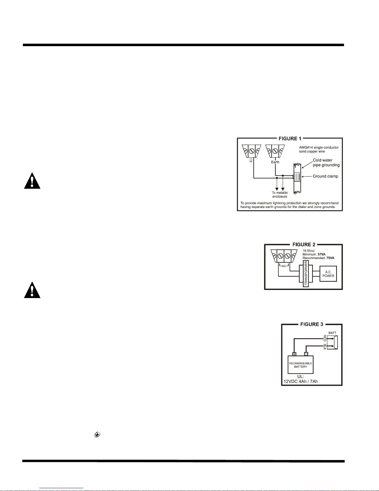
2.2 Earth Ground
Connect the zone and dialer ground terminals from the
control panel to the metallic enclosure and cold water pipe or
grounding rod as per local electrical codes. For UL
installations, the metallic enclosure must be grounded to the
cold water pipe or grounding rod.
For maximum lightning protection use separate earth
grounds for the zone and dialer grounds (see figure 1)!
Installation
INSTALLATION
2.3 Power
2.3.1 AC Power
Use a 16.5VAC (50-60Hz) transformer with a MINIMUM 40VA
rating to provide sufficient AC power (AUX outputs = 500mA
each); RECOMMENDED 75VA rating to provide maximum
power output (AUX outputs = 1A each). Do not use any switch-
controlled outlets to power the transformer. UL listed systems
require the K12 model T16V40 or T16V75 transformer.
Do not connect the transformer or the back-up battery until all wiring is completed!
2.3.2 Back-up Battery
We recommend connecting a back-up battery to power the control
panel, in case of power loss. UL installations require the use of a backup battery. Use a 12VDC 4Ah / 7Ah rechargeable acid/lead or gel cell
battery. Connect the back-up battery after applying the AC power.
When installing the battery, verify proper polarity, as reversed
connections will blow the battery fuse. Connect the "red" battery lead
to the positive battery terminal, and the "black" battery lead to the
negative battery terminal of the control panel. Use the Battery Charge
Current Jumper on the PCB to determine the charging current of the backup battery. With
the jumper ON, the charging current will be set at 350mA. With the jumper OFF, the
charging current will be set at 700mA.
2.3.3 Auxiliary Power Terminals
The 748 has two auxiliary outputs each of which can provide a maximum of 1A 12VDC with
a 75VA transformer and 500mA with a 40VA transformer (250mA 12VDC for 24hr standby on
UL installations). You can use the auxiliary power supply to power the motion detectors,
3
Page 8
Installation
keypads and other accessories in your security system. Their combined current consumption
(see Table 1) on each auxiliary output should not exceed 1A. The auxiliary supply is
microprocessor-protected against current overload and automatically shuts down if the
current exceeds 1.1A. Auxiliary power will resume once the overload condition has restored
The control panel conducts a dynamic battery test under load every 60 seconds. If the battery
is disconnected, or its capacity is too low, the [1] key in the trouble display mode will be on.
Key [1] also comes "on" if the battery voltage drops to 10.5 volts or less when the control
panel is running on the back-up battery (no AC). At 8.5 volts, the panel shuts down and all
We recommend conducting a "power-up" test on keypads installed far from the control panel.
To do so temporarily connect the keypads near the control panel and connect the transformer.
After 10 seconds, begin entering random commands on the keypad and verify that the
keypad "beeps" in response to these commands. Then open a zone to ensure that the
keypad and the control panel are responding to these signals. If the keypad does not respond
is present at the "AC"
terminals. If AC is present, check the keypad wiring and verify there isn't a short between the
"black" and "red" keypad wires. If the keypad does not respond, please contact your local
and within 1-60 seconds after performing the dynamic battery test (see below).
Table 1 - Current Consumption
Motion Detectors 10-50mA typ. 636/646 Keypads 15mA DC typ.
(see detector instructions for details) 30mA DC max.
708 Comm. Module 35mA DC typ. 642 LCD Keypads 40mA DC typ.
75mA DC max. 55mA DC max.
SRI-18 46mA DC typ
135mA DC max.
2.3.4 Battery Test
outputs close.
2.3.5 Keypad Function Test
and indicator lights do not illuminate, verify that approximately 16VAC
Paradox Distributor.
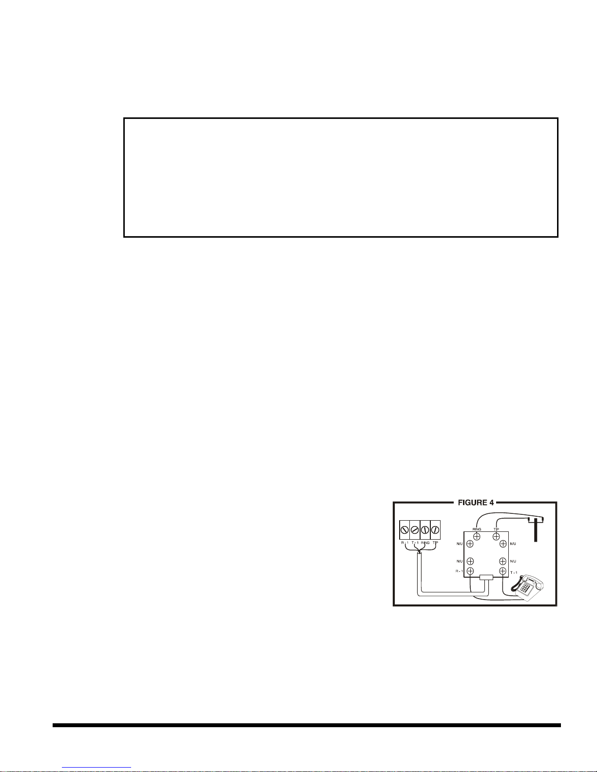
2.4 Telephone Line Connection
Connect the incoming telephone company wires into the TIP
and RING connections of the control panel. Then run the wires
from T-1 and R-1 to the telephone system as shown in figure 4.
4
Page 9

2.5 Bell/Siren Output
The BELL+ and BELL- terminals power bells and/or other warning
devices requiring a steady voltage output during an alarm. The bell
output supplies 12VDC upon alarm and can support two 20-watt or two
30-watt sirens. The bell output is microprocessor-controlled and will
automatically shut down if the current exceeds 3A. If the load on the
BELL terminals returns to normal (?3A), the control panel will re-instate
power to the BELL terminals. When connecting sirens (speakers with
built-in siren drivers) please verify correct polarity. Connect the positive
lead to the BELL+ terminal and the negative lead to the BELL- terminal
of the control panel as shown in figure 5. The Alarm Relay (optional),
which is rated at 5A, can also be used to power bells and/or other
warning devices requiring a steady voltage output during an alarm (see
figure 5). The Alarm Relay is activated (toggles to opposite state)
whenever the local bell/siren output is activated.
Installation
If the Bell/Siren output is not being used
output, the [4] trouble indicator (see section 11.12.3) will always be on. To avoid this, connect a
1K?resistor across the bell output.
when connecting a bell or siren to an optional relay
2.6 Programmable Outputs (PGM)
The Esprit “Plus” control panels include two fully
programmable output (PGM). When a specific event or
condition occurs in the system, a PGM can be used to
reset smoke detectors, activate strobe lights, open/close
garage doors and much more. The PGMs provide a
maximum 50mA output. If the current draw on a PGM
output is to exceed 50mA we recommend the use of a
relay as show in figure 6. The PGMs can be programmed
to toggle on and off from more than a thousand different
events. For example, PGM1 can open and close an
automatic garage door by pressing keys [1] and [2]
simultaneously on the keypad. For details on how to
program the PGMs, refer to section 9.
2.7 Keypad & Keyswitch Connections
Connect the four keypad connections labeled RED, BLACK, GREEN
and YELLOW to the corresponding colour terminals on the control
panel as indicated in figure 7. Note, on some keypads you may
have to remove the back panel to make the connections.
Connect the keyswitch to the “GRN” and “BLK” terminals of the
control panel as shown in figure 7. To enable this function
please refer to sections 8.5 and 11.8 for more information on
keyswitches.
2.8 Keypad Zone Connections
Each keypad comes with one input terminal, allowing you to connect one detector or door contact
directly to the keypad.
5
Page 10

If a keypad has the ATZ (zone doubling) feature, two detection devices can be connected to one
input terminal. Each device will be assigned a zone (see table below) and each will transmit a
separate alarm code, therefore, capable of adding one or two zones to your security system.
Regardless of the number of keypads in the system, the control panel supports a maximum of two
Note if using two keypad zones, one keypad must be defined as keypad zone 1 while the other
must be defined as keypad zone 2. Unless you are using an LCD keypad with the ATZ (zone
doubling) feature enabled, in which case the LCD will automatically define the keypad zones. The
If the keypad zone input terminal is not being used, disable it by shorting the blue zone wire with
COM
Installation
Example: A door contact located at the entry point of an establishment can be wired
directly to the input terminal of the entry point keypad instead of wiring the door contact
all the way to the control panel.
keypad zones.
Example 1: A security installation is comprised of five keypads. Of these five keypads
only two can have their zone input terminals enabled (see figure 9). The other three
keypads must have their zone input terminals disabled as described below.
Example 2: A security installation is comprised of three 636 keypads and two 642 LCD
keypads. You can enable the ATZ (Zone Doubling) feature on one of the 642 keypads,
providing you with 2 zones on one keypad input terminal (see Figure 10). The remaining
four keypads must have their input terminals disabled as described below.
control panel will recognize these added zones as shown in the table below.
Disabling 636/646 Keypad Zones:
the black COM wire of the keypad.
Disabling 642 Keypad Zones:
If the keypad zone input terminal is not being used, disable it by shorting the ZONE and
terminals of the keypad with a 1K? resistor.
Keypad Zone Recognition
If using an LED keypad simply set the Zone Select Jumper at the back of the keypad:
Zone Select Jumper "OFF" = Keypad Zone 1
Zone Select Jumper "ON" = Keypad Zone 2
Note:
If the zone select jumper is changed, the control panel will only recognize the change
when the keypad is disconnected and re-connected.
If using an LCD keypad with ATZ disabled, program the keypad definition as follows:
Keypad Programming Mode, option [2] (Keypad Options); Key [3] OFF = Keypad Zone 1
Keypad Programming Mode, option [2] (Keypad Options); Key [3] ON = Keypad Zone 2
The control panel will display open keypad zones as follows:
748 and 748 EXPRESS
Kpd Zone 1 = Zone [13]
Kpd Zone 2 = Zone [14]
Note: When the ATZ feature is enabled in the control panel, it will not be able to distinguish
between zone 13 and keypad zone 1 and between zone 14 and keypad zone 2
(see section 2.10)
6
Page 11

Installation
Once the keypad zones have been defined you must enable "Keypad Zone Supervision" (see
section 7.13 & 7.14) in the control panel. Figures 8 and 9 demonstrate typical keypad zone input
installations.
2.9 Single Zone Input Terminal Connections
The system hardware recognizes the following single zone input terminal connections. For more
information on programming the options mentioned below refer to ZONE DEFINITIONS in section 7.
2.9.1 N.C. Contacts, Without EOL Resistor
If your security installation does not require
7
Page 12
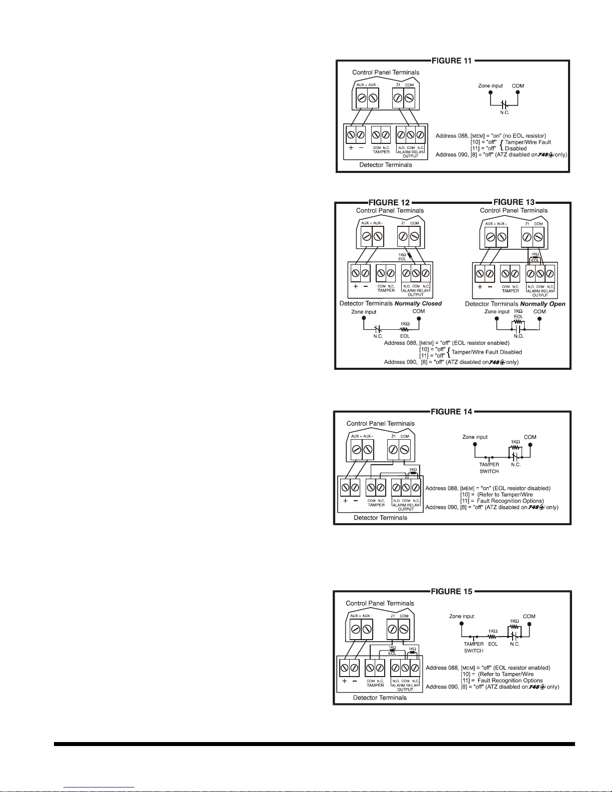
Installation
tamper or wire fault detection, connect the
detection devices and program the control
panel as shown in figure 11. This setup will
communicate an open or closed zone to the
control panel, displaying open zones on the
keypad. Do not use devices with normally
open contacts in this setup, as this will
cause the control panel to remain in alarm.
2.9.2 N.O. and N.C. Contacts, With EOL Resistor (UL)
If your security installation does not require
tamper or wire fault recognition but some
detection devices will use normally open
contacts. Connect all detection devices
using a 1K? end of line (EOL) resistor
and program the control panel as shown
in figures 12 and 13. This setup will
communicate an open or closed zone to
the control panel, displaying open zones
on the keypad.
2.9.3 N.C. Contacts, Without EOL Resistor, With Tamper Recognition
If your security installation requires tamper
recognition, all detection devices must
use normally closed contacts. Connect
the devices and program the control
panel as shown in figure 14. This setup
will communicate an open or closed zone
to the control panel, displaying open
zones on the keypad. The control panel
will also communicate any detected
tampers (cuts) as per Tamper/Wire Fault
Recognition Options (see section 10.7).
2.9.4 N.C. Contacts, With EOL Resistor, With Tamper and Wire Fault
Recognition (UL)
If your security installation requires tamper
(cut) and wire fault (short) recognition, all
detection devices must use normally
closed contacts. Connect the devices and
program the control panel as shown in
figure 15. This setup will communicate an
open or closed zone to the control panel,
displaying open zones on the keypad.
The control panel will also communicate
any detected tampers (cuts) and/or wire
faults (short) as per Tamper/Wire Fault Recognition Options (see section 10.7).
8
Page 13

2.10 Advanced Technology Zone (ATZ) Connections
This feature is not available on the 748 EXPRESS control panel.
Enabling the ATZ feature (see section 7.2) allows you install two detection devices per input
terminal, therefore, doubling zone capacity of the control panel. Advanced Technology Zoning is a
software-oriented feature, there is no need for extra modules, simply install the devices as shown
in figures 17 to 19. The control panel will recognize the installed devices as shown in figure 16. The
extra zones function exactly like any other zone displaying zone status on the keypad and sending
separate alarm codes for each zone. For more information on programming the options mentioned
in the following sections refer to ZONE DEFINITIONS in section 7.
Installation
When ATZ is enabled, keypad zones are recognized as zones 13 and 14. This means that the
control panel will not be able to distinguish between zone 13 and keypad zone 1 and
between zone 14 and keypad zone 2.
2.10.1 N.C. Contacts, Without EOL Resistor
If your security installation does not require
tamper or wire fault recognition but you are
using the ATZ feature, connect the detection
devices and program the control panel as
shown in figure 17. Do not use devices with
normally open contacts, as this will cause the
system to remain in alarm. This setup will
communicate the status of each device to the
control panel (see figure 16), displaying open
zones on the keypad.
9
Page 14
Installation
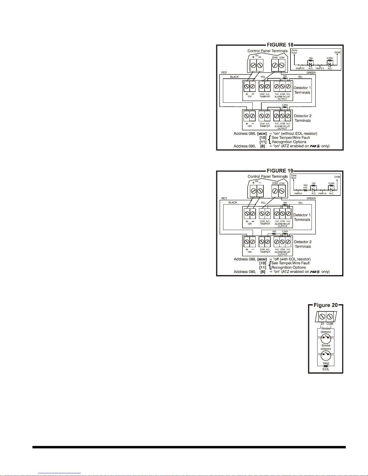
2.10.2 N.C. Contacts, Without EOL Resistor, With Tamper Recognition
If your security installation requires tamper
recognition and you are using the ATZ feature,
connect the detection devices and program
the control panel as shown in figure 18. Do not
use devices with normally open contacts, as
this will cause the zone to remain open. This
setup will communicate the status of each
zone to the control panel (see figure 16),
displaying open zones on the keypad. The
control panel will also communicate any
detected tampers (cuts) on the system as per
Tamper/Wire Fault Recognition Options (see
section 10.7).
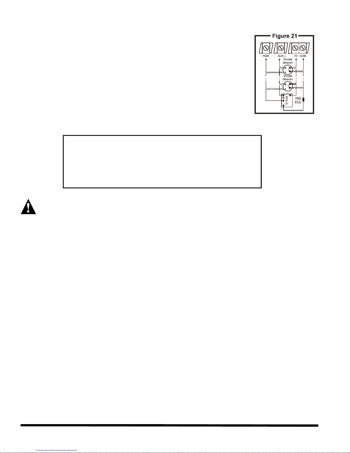
2.10.3 N.C. Contacts, With EOL Resistor, With Tamper & Wire Fault
Recognition (UL)
If your system requires tamper (cut) and wire
fault (short) recognition, connect two detection
devices to one input terminal with a 1K? end
of line (EOL) resistor and program the control
panel as shown in figure 19. Do not use
devices with normally open contacts, this will
cause the zone to remain open. This setup will
communicate the status of each zone to the
control panel (see figure 16), displaying open
zones on the keypad. Any tampers (cuts)
and/or wire fault (shorts) detected on the
system are communicated as per Tamper/Wire
Fault Recognition Options (see section 10.7).
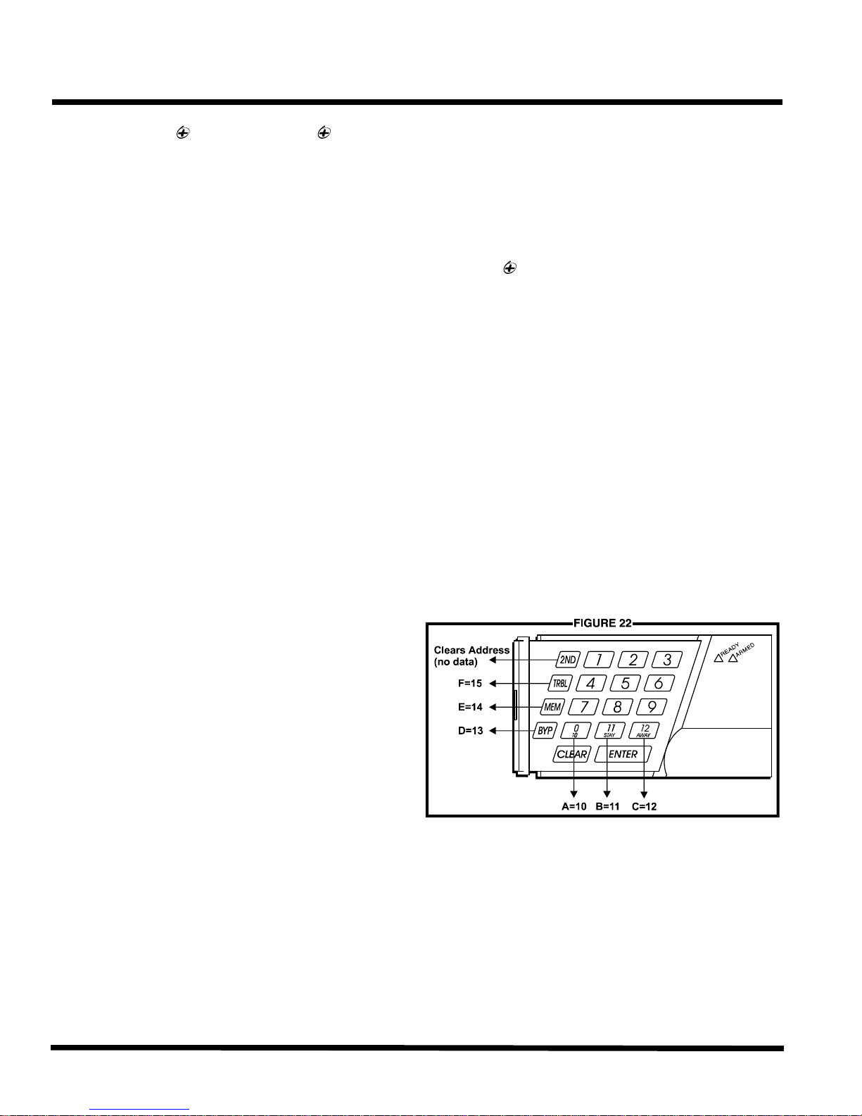
2.11 Fire Circuit
If your security installation requires the use of smoke detectors, define zone 3 as a
"24-hour" fire zone; please refer to section 7.5.
2.11.1 Standard Installation
Connect the smoke detectors to zone 3 as shown in figure 20. Note that a fire
zone must use a 1K? EOL resistor. If there is a line short or if the smoke
detector becomes active, whether the system is armed or disarmed, the
control panel will generate an alarm (see Fire Alarm Output figure on page 30).
If the line is "open", the control panel will send a "fire loop" trouble report to the
central station and trouble indicator, key [11], will appear in the keypad’s
trouble display.
10
Page 15
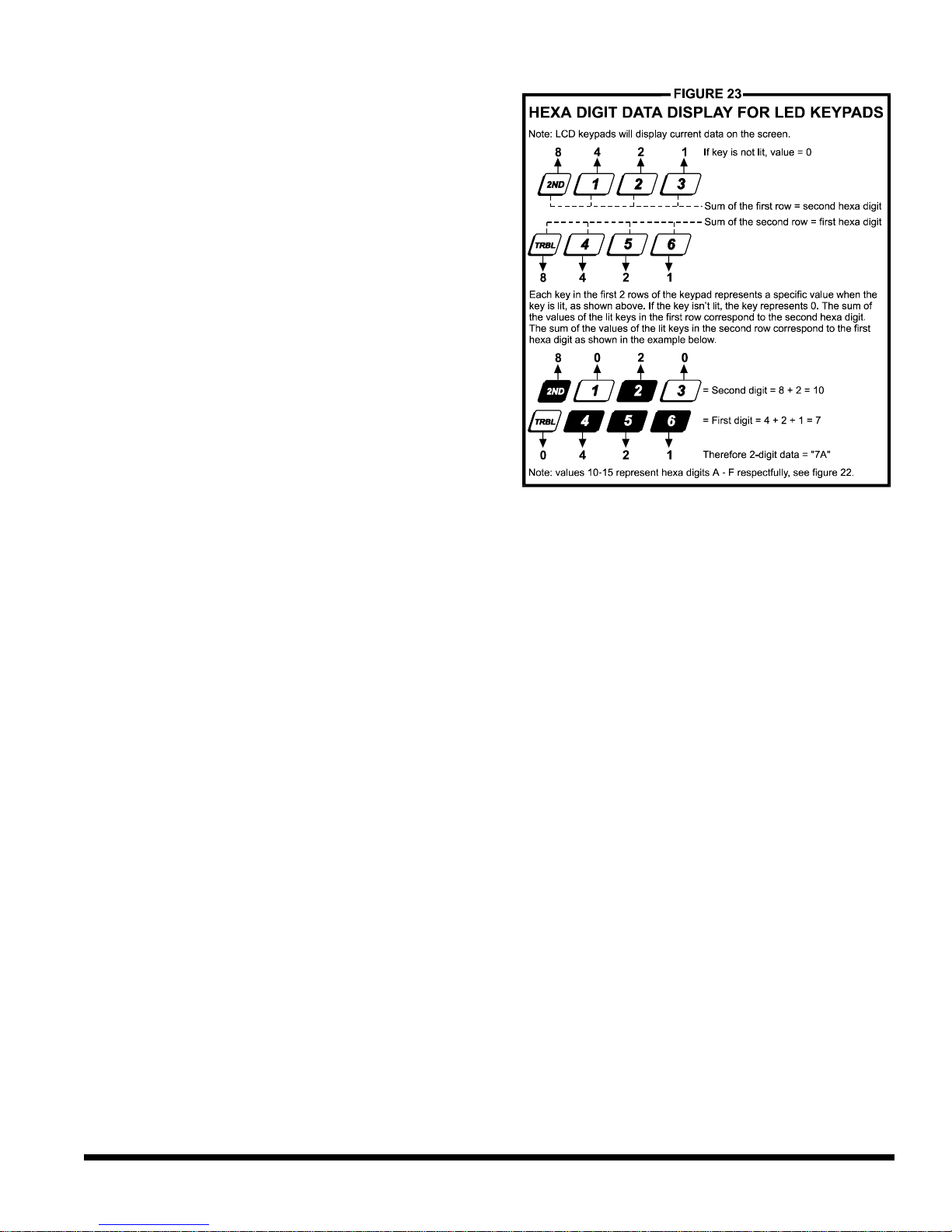
2.11.2 UL Installation
For UL installations, use a 4-wire, latching, smoke detector (UL Falcon Model 5454). To supervise the power supply, install an "end
of line" relay (Model MR3). Connect the smoke detectors and relay
as shown in figure 21. In the event power is interrupted the relay will
cause a FIRE TROUBLE report to be generated (see section 7.5).
To reset (unlatch) the smoke detectors after an alarm, momentarily
interrupt power to the detectors. To do so, verify that the negative (-)
of the smoke detectors is connected to a PGM. Set the PGM for
"Timed N.C." (normally closed), and program the PGM to "open"
when any two keys on the keypad are pressed simultaneously. For
more information on programming the PGM refer to section 9.
EXAMPLE: To program PGM1 to conduct a smoke detector reset
when the [CLEAR] and [ENTER] keys are pressed at the same time.
Address 039 = [BYP] [2ND]
Address 040 = [5] [10]
Address 042 = [2ND] [6]
Address 056 = [10] [10] [4]
Installation
It is recommended to connect all 4-wire smoke detectors using a daisy chain configuration.
2.12 Serial Output Connector
The four pin Serial Output Connector is used to connect additional devices such as the 708DVACS
communicator, the Esprint printing module and the SRI-18 PGM Expander Module to the control
panel. For serial output connector specifications refer to section 1.3.
11
Page 16

Only the installer code allows you to program all control panel settings, except the Master and User
codes. To program any setting in the control panel you must enter the programming mode by
nstaller code. The installer code contains six digits and
nel can accept 4-digit codes, when
[10] [10] [2]
You can not use the installer code to program the master and user codes. Only the master and
When programming user codes an option for either 4-digit or 6-digit access codes can be
git code will allow the person
forced to disarm a system, a User can enter the User Code #48 instead of their
Program 147 into address 058 to lock all programming. Hence, performing a hardware reset (see section
Access Codes
ACCESS CODES
3.1 Installer Code
Streamline - Section 00 ? Hexa Programming - Addresses 000-002
Default: 748 = 484848/ 748 EXPRESS = 747474
pressing the [ENTER] key followed by the i
each digit can be any value from 0 to 9. Although the control pa
programming the installer code, always enter six digits. To change the installer code press:
[ENTER] + Installer Code + [10] [10] [10] + First 2 digits + [10] [10] [1] + Next 2 digits +
+ Final 2 digits + [ENTER]
3.2 Master & User Codes
Default Master Code: 474747
user 1 codes can program these access codes. (See section 11.1)
3.3 User / Access Code Length
Feature Select Programming ? Address 088, key [9]
Default: 6-digit Access Codes
programmed. When the 4-digit option is selected, entering a 4-di
access. Using the 6-digit option, entering 6 digits is required to allow access.
Key [9] "Off": 6-digit Access Codes
Key [9] "On": 4-digit Access Codes
[ENTER] + Installer Code + [10] [8] [8] + [9] On/Off + [ENTER] twice
3.4 Duress
Feature Select Programming ? Address 090, key [10]
Default: Duress Disabled
When unwillingly
usual code. This code will disarm the system and send a silent alert (Duress Code) to the Central.
Key [10] "Off": Duress Disabled
Key [10] "On": Duress Enabled
[ENTER] + Installer Code + [10] [9] [10] + [10] On/Off + [ENTER] twice
3.5 Installer Lock
Decimal Programming ? Address 058
Default: Address Empty
10.12) will not affect the current settings. To remove the installer lock, enter any value besides 147.
[ENTER] + Installer Code + [10] [5] [8] + [1] [4] [7] + [ENTER]
12
Page 17
PROGRAMMING METHODS
The 748 & 748 EXPRESS Control Panels can be programmed using either the keypad or the
Espload Software. We highly recommend programming the control panels using the Espload
Software, as it simplifies the process and reduces the potential of data entry errors. You can also
program the control panels manually by using a keypad.
4.1 Espload Software
With the Espload Software, you can program the 748 family of control panels remotely via
modem or locally using an ADP-1 adapter. The advanced Espload software can execute fast
uploads or downloads and provides many powerful features. These include a comprehensive
"monitoring" mode to oversee all panel activity, a "scheduler" to initiate pre-programmed tasks at
set intervals, and a "batch" mode to carry out pre-programmed tasks following a call from the
control panel. Using Espload there is no limit to the number of account files or panel defaults
created and you can assign thousands of programming combinations to the PGM outputs. Espload
can also be converted to the language of your choice. Contact your local Paradox Distributor for
your FREE copy of the Espload software.
Programming Methods
4.2 Keypad
When programming, use the supplied "Programming Guide" to keep track of which addresses were
programmed and how. Before you begin programming the control panel, we recommend you read
sections 5 through 11 of this manual in order to acquire a good understanding of the control panel
and its many features. When programming with the keypad, certain addresses are programmed
using different methods. These methods are described in detail below. Each section in this manual
will reference the appropriate programming method.
4.2.1 Hexa Programming
Addresses 000 to 043 and 300 to 527
are programmed using the Hexa
Programming method. In this mode,
you can enter any hexa-digit from 0-F
where keys [1] to [9] represent digits 1
to 9 respectively; the other keys
represent hexa-digits A to F as shown
in figure 22. To program using the
Hexa Programming method:
13
Page 18
This is an alternate method to Hexa Programming. The addresses (000-043 and 300-527)
programmed in the Hexa Programming method are grouped into 67 sections where each
section contains four addresses (i.e. section 00 = addresses 000-003). Using this method
allows you to program 8 digits (4 addresses) without having to exit and re-enter addresses.
Note: the keypad will not display the current data in the Hexa Streamlined Programming
keys will flash to indicate you are in streamlined programming mode
The keypad will "beep" to indicate that the section has been programmed, data is saved
Addresses 044 to 061 are programmed using the Decimal Programming method. Values
entered must contain three digits from 000 to 255 (where the [10] key = 0). To program using
Programming Methods
1) Press [ENTER] + Installer Code
2) The [ENTER] key will flash indicating
you are in programming mode
3) Enter the desired 3-digit address
4) The keypad will display the 2-digit
data currently saved at this address
as described in figure 23
5) Enter 2-digit data; after entering data
you do not need to press enter, the
software will automatically save the
data into the selected address
6) Return to step 2 to continue
programming or press [CLEAR] to exit
programming mode
4.2.2 Hexa Streamlined Section Programming
When entering the final digit, the software will automatically advance to the next section.
Example: If you complete the "Programming Guide" with the desired data, you
can program the 68 sections by entering all digits without pressing [ENTER] or
entering any other addresses. This greatly reduces programming time.
method. To program using the Hexa Streamlined Section method:
1) Press [ENTER] + Installer code + [7]
2) The [ENTER] and [2ND]
3) Enter 2-digit section (00-67)
4) The [ENTER] key will remain on and the [2ND] key will turn off
5) Enter 8-digit data to program the section
6)
and the software has advanced to the next section
7) Return to step 4 to continue programming or press [CLEAR] to exit programming mode
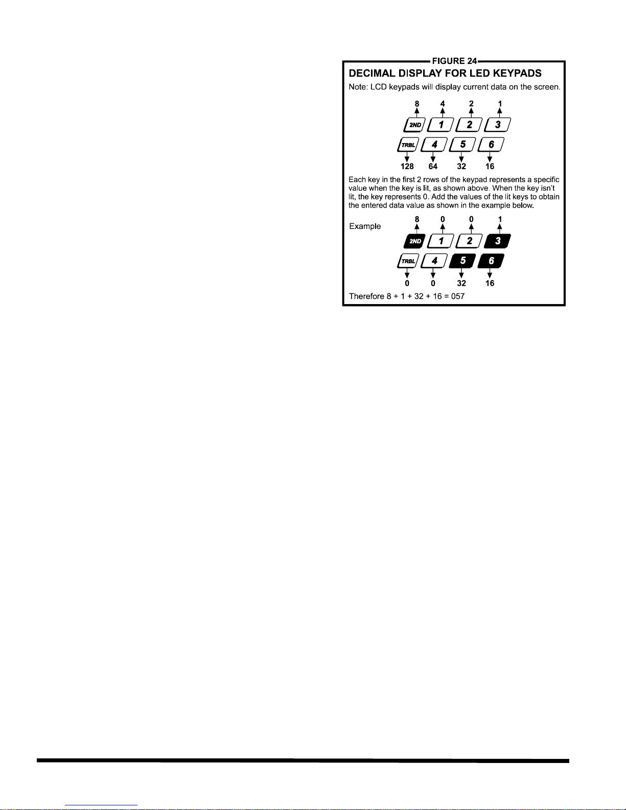
4.2.3 Decimal Programming
the Decimal Programming method:
14
Page 19
Programming Methods
1) Press [ENTER] + Installer Code
2) The [ENTER] key will flash to indicate you
are in programming mode
3) Enter 3-digit address (044-061)
4) The keypad will now display the current
3-digit data currently saved at this
address as described in figure 24
5) Enter 3-digit data (decimal) value; after
entering data you do not need to press
[ENTER], the software will automatically
save the data into the selected address
6) Return to step 2 to continue
programming or press [CLEAR] to exit
programming mode
4.2.4 Feature Select Programming
Addresses 062 to 126 are programmed using the Feature Select Programming method. In
this method, every key in each address on the keypad represents an option or feature.
Pressing a key will display it on the keypad and pressing it again will extinguish the key. The
On/Off status of each key determines the selected feature. To program using the Feature
Select Programming method:
1) Press [ENTER] + Installer Code
2) The [ENTER] key will flash to indicate you are in programming mode
3) Enter 3-digit address (062-126)
4) After entering the address, the keypad will display the feature selection status. The
On/Off status of the keys determines the selected features as described in the
"Programming Guide" and in the appropriate sections of this manual. Turn the keys
On/Off by pressing the appropriate key until the desired options are set. Then press the
[ENTER] key to accept, there will be a confirmation "beep" indicating the options have
been accepted. The [ENTER] key will flash to indicate that the software is awaiting the
next address entry
5) Return to step 3 to continue programming or press [CLEAR] to exit programming mode
4.2.5 Key Access Programming
This method allows for quick programming of features without entering addresses or section
numbers. The following features are programmed using the installer code as well as the
master and user 1 codes.
? Installer Test Mode: see section 10.9
? Auto Arm Time: see section 8.1.1 ? Cancel Communication: see section 5.7
? Answer Espload: see section 5.6 ? Manual Test Report: see section 6.8
? Call Espload: see section 5.5 ? Panel Time: see section 10.5
15
Page 20

The following two options will define how the control panels answer an incoming call from a
In order for the Espload software to remotely communicate with the control panel, call the
in address 003
with any value from 1-F (see table 2 below), this value represents the delay period the control
panel will wait between the first and second call. Using the Espload software, call the installation
on the keyboard to hang-up. After hanging up, the
Espload software will immediately call the installation site back. If the installation site is called back
within the programmed delay period, the control panel will override the answering machine or
or [1] as the first digit in
represents the number of rings the control panel will wait before picking-up the
line. If the line is not answered after the number of re-programmed rings, the control panel will
answer the call. Note the control panel resets the "ring" counter every 64 seconds. Therefore, if
someone or an answering machine answers a call before the number of pre-programmed rings
has elapsed, the control panel will keep the number of rings in memory for 64 seconds. If you hang-
up and call the installation site back within 64 seconds, the control panel will continue to count the
number of rings from the first call. After reaching the total number of rings, the control panel will
answer the call. The number of rings can be set from 1-15 by programming the second digit at
to disable this option.
Panel Settings for Espload
PANEL SETTINGS FOR ESPLOAD
5.1 Panel Answer Options
Streamline - Section 00 ? Hexa Programming - Address 003
Default: Answering Machine Override Disabled & Maximum 8 rings
computer using the Espload software.
installation site twice using the Espload Software. To do so, program the first digit
site and on the second ring press [ENTER]
service by picking-up on the first ring. To disable this option program [2ND]
address 003.
Example: A security installation is using an answering machine set to answer after 3
rings, the first digit at address 003 has been programmed with [5] (40 sec.) and the
second digit has been programmed with 8. When you call the installation site with the
Espload software the first time, wait two rings and press [ENTER] on the keyboard. The
Espload software will immediately call the installation site back. If the second call is made
within 40 seconds, the panel will pick up the line on the first ring. If it takes more than 40
seconds, the panel will not answer on the first ring and the answering machine will
answer after three rings.
Table 2 - Answering Machine Override Options
[2ND] or [1] = Answering Machine Override disabled
[2] = 16 seconds [4] = 32 seconds [6] = 48 seconds [8] to [TRBL] = 60 seconds
[3] = 24 seconds [5] = 40 seconds [7] = 56 seconds
[ENTER] + Installer Code + [10] [10] [3] + 1st digit + 2nd digit (1-15 rings) + [ENTER]
The second digit
address 003 with any hexa-digit from 1-F. Program the second digit with [2ND]
Example: Address 003 = [2ND] [8]. Using the Espload software, you call an installation
site where there is no answering machine or service and no one is home. Since there is
no one to answer the telephone call, the control panel will pick-up the line on the eighth
ring. If someone happens to be home and answers the telephone, say, after three rings,
the control panel will keep the three rings in memory for 64 seconds. If you hang-up and
call back the installation site within 64 seconds the control panel will answer the call on
16
Page 21

the fifth ring. If you call back after 64 seconds the "ring" counter will have been reset and
the control panel will answer the call on the eighth ring.
If you program four or less rings, the control panel will always reset the counter!
5.2 Panel Identifier
Streamline - Section 01 ??Hexa Programming - Addresses 004-005
This four-digit code identifies the control panel to the Espload software before initiating upload.
Program the same 4-digit code into the control panel and the Espload software before attempting to
establish communication. If the codes do not match, the control panel will not establish
communication. Enter any hexa digits from 0 to F.
[ENTER] + Installer Code + [10] [10] [4] + First 2 digits + [10] [10] [5] + Final 2 digits + [ENTER]
5.3 PC Password
Streamline - Section 01 ? Hexa Programming - Addresses 006-007
This four-digit download password identifies the PC to the panel, before beginning the download
process. Enter the same password into the Espload software and the control panel. If the passwords
are not the same, Espload will not establish communication. Enter any hexa digits from 0 to F.
Panel Settings for Espload
[ENTER] + Installer Code + [10] [10] [6] + First 2 digits + [10] [10] [7] + Final 2 digits + [ENTER]
5.4 Computer Telephone Number
Streamline Section 02 & 03 ? Hexa Programming - Address 008-015
The control panel will dial this telephone number when trying to initiate communication with the PC
(see section 5.5 Call Espload). There is no default telephone number and you can enter any
number from 0-9 up to a maximum of 16 digits. If you would like to enter any special keys or
functions refer to table 3 in section 6.3. If the telephone number contains less than 16 digits, press
the [TRBL] key to indicate the end of the telephone number.
[ENTER] + Installer Code + [7] + [10] [2] + Telephone Number (if <16 digits press [TRBL]) + [ENTER]
5.5 Call Espload
Key Access Programming ? key [TRBL]
The control panel will dial the telephone number entered at addresses 008-015 (see section 5.4) in
order to communicate with the Espload software. The control panel and the computer will verify that
the Panel Identifier and the PC Password match before establishing communication (see sections
5.2 and 5.3).
Press [ENTER] + (Installer, Master, or User 1 Code) + [TRBL]
5.6 Answer Espload
Key Access Programming ? Key [AWAY]
By entering the code sequence listed below, you can manually force the control panel to answer
any incoming calls from the Espload software. This option can also be used to perform an on-site
upload/download by connecting your computer directly to the control panel using an ADP-1 line
adapter and manually answering Espload from the control panel. In Espload go to:
17
Page 22

Set "Dialing Condition" to "Blind Dial". Program the panel telephone number in Espload and follow
Use the Installer Code to cancel all communication and erase any unreported events in the buffer
until the next reportable event. Use the Master or User 1 code to cancel communication attempts
For additional security, when a PC using the Espload software attempts to communicate with the
control panel, the control panel can hang-up and call the PC back in order to re-verify identification
codes and re-establish communication. When the control panel answers the call, it will verify if the
Panel ID and PC Passwords match and if they do, the control panel will hang-up and call the
Espload software back. The Espload software will automatically go into "wait for dial tone", ready to
(see
When the event buffer reaches 50% capacity, the control panel will make two attempts to establish
communication with a PC. The control panel will call the Computer Telephone Number (see section
5.4) programmed at addresses 008 to 015. The Espload software must be in "wait for dial tone"
mode. When the system establishes communication, it will upload the contents of the event buffer
to the Espload software. If communication is interrupted before transmission of the complete
contents of the buffer, or if after two attempts, communication is not established, the system will
wait until the event buffer is full before attempting to re-communicate with Espload. When the Event
Panel Settings for Espload
Main Menu ? Program Setup ? Modem & Printer Configuration
the instructions on the ADP-1 adapter. When the computer has dialed press:
[ENTER] + (Installer, Master, or User 1 Code) + [AWAY]
5.7 Cancel Communication
Key Access Programming ? key [STAY]
with Espload.
[ENTER] + (Installer, Master & User 1 Code) + [STAY]
5.8 Call Back
Feature Select Programming ? Address 086, key [4]
Default: Call Back Disabled
answer when the control panel calls back. Please note the Computer Telephone Number
section 5.4) must be programmed in order to use the "Call Back" feature.
Key [4] "Off": Call Back Disabled
Key [4] "On": Call Back Enabled
[ENTER] + Installer Code + [10] [8] [6] + [4] On/Off + [ENTER] twice
5.9 Automatic Event Buffer Transmission
Feature Select Programming ? Address 088, key [2ND]
Default: Automatic Event Buffer Transmission Disabled
Buffer is full, each subsequent new event will erase the oldest event in the buffer.
Key [2ND] "Off": Automatic Event Buffer Transmission Disabled
Key [2ND] "On": Automatic Event Buffer Transmission Enabled
[ENTER] + Installer Code + [10] [8] [8] + [2ND] On/Off + [ENTER] twice
18
Page 23

EVENT REPORTING
Event Reporting
19
Page 24

When a specific event occurs in the system, the control panel will attempt to report the appropriate
event code (if programmed) to the Central Station. The four available Reporting Options described
in the table below, define where the event codes are reported. In order to establish communication
with the Central Station the control panel will first access a telephone line and wait a maximum of 8
seconds for a dial tone. If a dial tone is recognized or if after 8 seconds there is no dial tone, the
control panel will dial the appropriate Central Station Telephone Number as defined by the
Reporting Options listed in the table below. If communication is established, the control panel will
transmit the events in the event buffer to the Central Station. If communication fails during
transmission, the control panel will dial the next central station telephone number, as defined by the
reporting options listed below, and report only those events not reported during the interrupted
Using regular reporting the event codes are reported to the central station using either
telephone number 1 or 2. The control panel will begin by dialing central station telephone
number 1. If communication fails, the dialer will hang up, wait a predetermined period and dial
central station telephone number 2. This sequence will repeat 4 times, switching back and
forth between the 1st and 2nd number (see figure 26 on the following page) until
communication is established. After eight unsuccessful attempts, the redial sequence ends
and a "communicator report failure" will appear in the keypad's trouble display (key [7] "on").
When the next event occurs (reportable or non-reportable), the control panel will begin the
, the control panel will report all Event Codes to Central
Station Telephone 2. If communication fails, the dialer will hang-up, wait a predetermined
period and dial the number again. The control panel will dial the number eight times until
communication is established (see figure 26 on the following page). After eight unsuccessful
attempts, the redial sequence ends and a "communicator report failure" will appear in the
keypad's trouble display (key [7] "on"). When the next event occurs (reportable or non-
, the control panel will report all Event Codes to Central Station
Telephone 1. Any ongoing communication (upload/download or reporting to Telephone 2) will
stop immediately and the panel will dial Telephone 1. If communication fails, the dialer will
hang-up, wait a predetermined period and dial the number again. The control panel will dial
the number eight times until communication is established (see figure 26 below). After eight
unsuccessful attempts, the redial sequence ends and a "communicator report failure" will
Event Reporting
6.1 Reporting Options
Feature Select Programming ? Address 086, key [11] & [12]
Default: Reporting Disabled
attempt. For information on Reporting Event Codes see section 6.6.
[ENTER] + Installer Code + [10] [8] [6] + [11] & [12] On/Off + [ENTER]
6.1.1 Reporting Disabled
The Control Panel will never transmit any event codes to the central station.
6.1.2 Regular Reporting
dialing sequence again.
6.1.3 Split Reporting
When the system is not in alarm
reportable), the control panel will begin the dialing sequence again.
When the system is in alarm
20
Page 25

Event Reporting
appear in the keypad's trouble display (key [7] "on"). When the next event occurs (reportable
or non-reportable), the control panel will begin the dialing sequence again.
6.1.4 Double Reporting
In double reporting, the control panel will report each event code to both central station
telephone numbers. The control panel will begin by attempting communication with central
station telephone 1 and if communication fails, the dialer will hang-up, wait a predetermined
period and dial the number again. The control panel will dial the number eight times until
communication is established (see figure 26). After eight unsuccessful attempts, the redial
sequence ends and a "communicator report failure" will appear in the keypad's trouble
display (key [7] "on"). If communication has been established and the event codes
transmitted or if after eight attempts communication has not been established, the control
panel will report the same Event Codes to Central Station Telephone 2.
6.2 Central Station Telephone Number 1
Streamline - Section 04 & 05 ? Hexa Programming - Addresses 016-023
The control panel will dial the programmed telephone number when reporting an event code to the
central station computer (see Reporting Options in section 6.1). For example, if the alarm system is
armed and a zone with a motion detector opens, the control panel may dial the telephone number
in order to send the programmed event code to the central station computer. There is no default
telephone number and you can enter any number from 0-9 up to a maximum of 16 digits. If you
would like to enter any special keys or functions, refer to table 3 below. If the telephone number
contains less than 16 digits, press the [TRBL] key to indicate the end of the telephone number.
[
ENTER
]
+ Installer Code +
[7]+ [10] [4]
+ Telephone Number +
[
ENTER] OR[TRBL
]
if number is <16 digits
21
Page 26

The control panel can communicate with two central station numbers. The control panel may at
see section 6.1. If the
central station does not have a second number, you must enter the same number as the first.
There is no default telephone number and you can enter any number from 0-9 up to a maximum of
16 digits. If you would like to enter any special keys or functions refer to table 3 below. If the
key to indicate the end of the
All report codes are preceded by a 3 or 4-digit system account code to ensure correct identification
to the central station, identifying from which security system the event originated. For example, if a
zone opens, the control panel will first send the account code followed by the appropriate report
code. In a partitioned system, the control panel can send a separate account code for each system.
This will identify to the central station from which partition the report code originated. To do so,
program a different number into each account code. Where account code #1 will represent “System
key followed by the 3-digit account number.
]
The following option will determine which format the control panel will use to communicate with the
. Using table 4 below, select the appropriate communication format. The first digit
represents the Communication Format for Central Station Telephone Number 1 and the second
Event Reporting
6.3 Central Station Telephone Number 2
Streamline - Section 06 & 07 ? Hexa Programming - Addresses 024-031
times dial the second number depending on the selected Reporting Options
telephone number contains less than 16 digits, press the [TRBL]
telephone number.
[
ENTER
]
+ Installer Code +
Enter special instructions in the telephone numbers using these keys:
[10] = the number "0" [BYP] = switch from pulse to tone while dialing
[11] =
*
[12] = # [TRBL] = end of telephone number
[7]+ [10] [6]
Table 3 - Telephone number Special Instructions
+ Telephone Number +
[MEM] = pause 4 seconds
[
ENTER] OR[TRBL
]
if number is <16 digits
Both Central Station Telephone Numbers must be programmed in order for event reporting
to function properly!
6.4 System Account Codes
Streamline - Section 08 ? Hexa Programming - Addresses 032-035
A" and account code #2 will represent “System B".
If partitioning is disabled, program the same value for both account numbers.
There are no defaults and you can enter any hexa digit from 0 to F. Please note if required, system
account codes can have 3 digits. To do so, press the [2ND]
[
ENTER
]
+ Installer Code +
[ENTER] + Installer Code + [7] + [10] [8] + [2ND] + 3-digit Account Code #1 + [2ND] 3-digit Account
Code #2 + [ENTER]
[7]+ [10] [8]
+ 4-digit Account Code #1 + 4-digit Account Code #2 +
[
ENTER
6.5 Communicator Formats
Streamline - Section 09 ? Hexa Programming - Address 038
Default: Ademco Slow for both numbers
Central Station. You can select a different communicator format for each Central Station Telephone
Number
22
Page 27

Event Reporting
digit represents the Communication Format for Central Station Telephone Number 2. Below you will
find a brief description of all available Communicator Formats.
[ENTER] + Installer Code + [10] [3] [8] + First digit = (Central Station Telephone #1) + Second digit =
(Central Station Telephone #2) + [ENTER]
6.5.1 Ademco Contact ID (all codes)
Please note that this format must use a 4-digit system account code (see section 6.4).
Ademco Contact ID is a fast communicator format that uses tone transmission instead of
pulse transmission. This communicator format also uses a pre-defined list of industry
standard messages and event codes that should suit most of your basic installation needs.
Using the "All Codes" format, the control panel will automatically generate the Contact ID
event codes (see table 5 below) for every event in addresses 300 to 527. Therefore, you do
not need to program addresses 300 to 527.
6.5.2 Ademco Contact ID (programmable codes)
Please note that this format must use a 4-digit system account code (see section 6.4). Ademco
Contact ID is a fast communicator format that uses tone transmission instead of pulse
transmission. Use the Ademco Contact event list of industry standard messages and event codes
found in the programming guide to program the desired event codes into addresses 300 to 527.
23
Page 28

This high-speed reporting format communicates 2-digit (00 to FF) events programmed at
addresses 300 to 527 at a speed of 2 seconds per event. Unlike other Ademco formats, the
Contact ID Event Codes are not used. Please note this format must use a 4-digit system
This format is the same as the Ademco contact ID (programmable codes) except there is no
verification of the report code sent (no handshake). Use this format in reporting situations where a
central station receiver is not connected to the telephone number. It is also useful for personal
reporting where a "handshake" is not required. For example, in "double reporting" mode, the first
central station number can be connected to a receiver, while the second can be used for personal
reporting using "no handshake" format. The panel will make two attempts to call the "no handshake"
The control panel supports the following pulse reporting formats (see table 4 on the previous
An Event Code is a 2-digit hexadecimal value, consisting of numbers from 00-FF. Each address between
". When an
event occurs in the system, the control panel will attempt to transmit the 2-digit Event Code programmed
at the corresponding address to the central station. The method of Event Code transmission is
(see section 6.1).
Note:You do not need to program addresses 300-527 if using the Ademco Contact I.D. (all codes)
Whenever the system is armed, the control panel will send the programmed event code to
Whenever the system is disarmed, the control panel will send the programmed event code to
Whenever an alarm occurs, the control panel will send the programmed event code to the
The control panel will send the programmed event code to the Central Station as soon as the
rm or as soon as the zone closes after bell cut-off.
Event Reporting
6.5.3 Ademco Express
account code (see section 6.4).
6.5.4 DTMF - no handshake
number. Please note this format must use a 4-digit system account code (see section 6.4).
6.5.5 Standard Pulse Formats
page): Ademco slow, Silent Knight, Sescoa, and Radionics.
6.6 Reporting Event Codes
Streamline - Sections 11 to 67 ? Hexa Programming - Addresses 300-527
300 and 527 represents a specific event, as described below and in the "Programming Guide
dependent on the Communicator Formats (see section 6.5) and the Reporting Options
format. If you plan to program most of the event code addresses, we suggest you use the Hexa
Streamlined Section Programming Method as described in section 4.2.2. Otherwise, use the Hexa
Programming Method as described in section 4.2.1.
6.6.1 Arming Codes
Streamline - Sections 11 to 23 ? Hexa Programming - Addresses 300-349
the Central Station identifying who or how the system was armed.
6.6.2 Disarming Codes
Streamline - Sections 23 to 35 ? Hexa Programming - Addresses 350-399
the Central Station identifying who disarmed the system.
6.6.3 Alarm Codes
Streamline - Section 36 to 41 ? Hexa Programming - Addresses 400-423
Central Station identifying which zone generated an alarm.
6.6.4 Restore Codes
Streamline - Sections 42 to 47 ? Hexa Programming - Addresses 424-447
zone closes after having generated an ala
For more information, please see Report Zone Restore Options in section 6.11.
24
Page 29

Event Reporting
6.6.5 Shutdown Codes
Streamline - Sections 48 to 53 ? Hexa Programming - Addresses 448-471
If the Auto Zone Shutdown (see section 7.11.1) feature is enabled, the control panel will send
the programmed event code to the Central Station identifying which zones were shutdown.
6.6.6 Tamper/Trouble Codes
Streamline - Sections 54 to 56 ? Hexa Programming - Addresses 472-483
If the Tamper/Wire Fault Recognition Options are disabled (see section 10.7), the control
panel will never transmit these event codes. Otherwise, whenever a tamper occurs on a
zone, the control panel will send the programmed Event Code to the Central Station. With
Advanced Technology Zoning (ATZ) enabled (see section 7.2) each Tamper Code address
will represent two zones (e.g. Tamper 1 = zones 1 & 2, Tamper 2 = zones 3 & 4, etc.). The
control panel will send the programmed Event Code when a tamper occurs on either zone.
6.6.7 Trouble/Restore Codes
Streamline - Sections 60 to 63 ? Hexa Programming - Addresses 496-511
Each of the these addresses represent a specific trouble or restore condition. The control
panel will report the appropriate event code to the central station when one of the following
conditions occurs or after the condition has returned to normal.
496 - Max. Auxiliary Current: the current draw from auxiliary is ? 1.1A.
504 - Max. Auxiliary Current Restore
497 - Bell Disconnect/Max. Bell Current: Bell is disconnected or Bell current is ? 3A.
505 - Bell Disconnect Restore: No restore code for bell current.
498 - Battery Disconnect/Low Voltage: Battery disconnected or battery voltage ? 10.5V.
506 - Battery Disconnect/Low Voltage Restore
499 - Power Failure: Voltage on AC input is ? 12.5V.
507 - Power Failure Restore
500 - Fire Loop Trouble: A tamper occurs on a fire zone (Zone 3/24hr.).
508 - Fire Loop Trouble Restore
501 - Timer Loss: The control panel detects a loss in the panel timer.
509 - Timer Programmed
502 to 503 - Reserved for Future Use
510 - All Tamper/Trouble Codes (see section 6.6.6) have returned to "normal".
511 - TLM Trouble Restore: Telephone line has restored after the TLM (see section 10.1)
has detected the loss of a telephone line.
6.6.8 Special Codes
Streamline - Sections 64 to 67 ? Hexa Programming - Addresses 512-527
Each address represents a special condition in the system. When one of these special
conditions occur, the control panel will report the event code associated with the address.
512 - Test Report: The test report has been activated either manually (see section 6.8) or
automatically (see section 6.7).
513 - Panic 1: Keys [1] and [3] or a PS1 is pressed to activate a Panic 1 alarm
514 - Panic 2: Keys [4] and [6] are pressed to activate a Panic 2 alarm
515 - Panic 3: Keys [7] and [9] are pressed to activate a Panic 3 alarm
For more information on Keypad Panic Options see section 10.4
516 - Late To Close: "Timed" Auto Arming is enabled (see section 8.1) and the system has
not automatically armed itself at the specified time.
517 - No Movement: "No Movement" Auto Arming is enabled (see section 8.2) and no
movement has occurred for the designated amount of time.
25
Page 30

Whenever the system is "Away" armed, "Stay" armed, or armed
An alarm occurs shortly after the system has been armed, refer to
The Duress feature is enabled (see section 3.4) and a User disarms the
The report code programmed at address 512 will be reported to the central station after the number
of days programmed at address 046 and the time programmed at address 047 (hours) and 048
(minutes) has elapsed. To disable this feature, program 000 at address 046. Also note that if
[10] [4] [8]
Activating the manual test report will send the Event Code programmed at address 512 to the
After a power failure, the control panel will delay transmission of the event code programmed at
The system will transmit the recent close event code programmed at address 519 if after arming
the system, an alarm occurs within the period programmed at this address (001 to 255 minutes).
Event Reporting
518 - Partial Arming:
while one or more zones are bypassed.
519 - Recent Close:
Recent Close Delay in section 6.10.
520 - Duress:
system using the User Code #48.
524 - Log-In (Espload): Espload software is used to communicate with the Control Panel.
525 - Program Change: The installer code is used to enter the programming mode
521 to 523 - Reserved for Future Use
526 to 527 - Reserved for Future Use
6.7 Auto Test Report
Decimal Programming ? Addresses 046-048
Default: Auto Test Report Disabled
[2ND][2ND] is programmed at address 512 nothing will be reported.
[ENTER] + Installer Code + [10] [4] [6] + 3 digits (days) + [10] [4] [7] + 3 digits (hours) +
+ 3 digits (minutes) + [ENTER]
6.8 Manual Test Report
Key Access Programming ? key [BYP]
Central Station.
[ENTER] + (Installer, Master, or User 1 Code) + [BYP] + [ENTER]
6.9 Power Failure Report Delay
Decimal Programming ? Addresses 054
Default: 30 minutes
address 499 by the period programmed at this address (001 to 255 minutes).
[ENTER] + Installer Code + [10] [5] [4] + 3-digit decimal value (001-255) + [ENTER]
6.10 Recent Close Delay
Decimal Programming ? Addresses 060
Default: Recent Close Delay Disabled
Program 000 into address 060 to disable this feature.
[ENTER] + Installer Code + [10] [6] [10] + 3-digit decimal value (001-255) + [ENTER]
26
Page 31

6.11 Report Zone Restore Options
Feature Select Programming ? Address 088; key [BYP]
Default: Zone Restore Codes Transmit on Bell Cut-Off
With the [
BYP
] key "Off", the report codes programmed at addresses 424-447 (see Restore Codes in
section 6.6.4) will only transmit if the zone has returned to normal after bell cut-off (see section 8.11).
With the [
BYP
] key "On", the codes will transmit as soon as the zone returns to normal (zone closure).
Key [BYP] "Off": Report on Bell Cut-Off
Key [BYP] "On": Report on Zone Closure
[ENTER] + Installer Code + [10] [8] [8] + [BYP] On/Off + [ENTER]
6.12 Report Code Disarming Options
Feature Select Programming ? Address 088; key [TRBL]
Default: Disarming Codes Transmit on User Disarming
With the [TRBL] key "OFF", the Disarming Codes programmed at addresses 350-399 (see in
section 6.6.2) will transmit whenever a User disarms the system. With the [TRBL] key "ON", the
control panel will transmit these codes when a User disarms a system in alarm.
Key [TRBL] "Off": Always Report Disarm
Key [TRBL] "On": Report Disarm Only After Alarm
[ENTER] + Installer Code + [10] [8] [8] + [TRBL] On/Off + [ENTER]
Event Reporting
27
Page 32

Zone Definitions
ZONE DEFINITIONS
28
Page 33

7.1 Zone Speed
Decimal Programming ? Address 053
Default: 600mS
The zone speed applies to all zones whether the system is armed or disarmed. The zone speed
defines how quickly the control panel will respond to an open zone. The control panel will not
display and/or respond to an open zone until the programmed zone speed elapses. All other zone
definitions and options do not come into effect until the zone speed has elapsed.
Example: The system is armed and the zone speed is set for 1.2 seconds. A zone opens
and closes in less than 1.2 seconds the control panel will not respond (i.e. no reporting,
no alarm and no display on keypad).
The zone speed can be set from 15ms to 3.8s (001 to 255 X 15ms). This feature prevents any
momentary glitches in the system from causing an alarm or unnecessary reporting.
[ENTER] + Installer Code + [10] [5] [3] + 3 digit decimal value (001-255) + [ENTER]
7.2 Advanced Technology Zoning (ATZ)
Feature Select Programming ? Address 090, key [8]
Default: ATZ Disabled
This feature is not available on the 748 EXPRESS control panels. Enabling the ATZ feature allows
you to install two detection devices per zone input. Each detection device will have its own zone number
and each will transmit a separate alarm code that will display on the keypad. For information on how to
connect the detection devices and how the panel recognizes them, please refer to section 2.10.
Zone Definitions
Key [8] "Off": ATZ Disabled
Key [8] "On": ATZ Enabled
[ENTER] + Installer Code + [10] [9] [10] + [8] On/Off + [ENTER]
7.3 Intellizones
Feature Select Programming ? Addresses 092 & 094, keys [1] to [12]
If an alarm condition occurs on a zone identified as Intellizone, the control panel will trigger a timer
and will not generate an alarm until one of the following conditions occurs within a specified period
(see Intellizone Time Delay below):
? An alarm condition occurs on another zone during intellizone time delay.
? The zone that is in alarm has restored and re-occurred during intellizone time delay.
? The zone that is in alarm remains in alarm the entire intellizone time delay.
Note: Intellizone timer will only begin after the zone speed period has elapsed (see section 7.1).
Do not use the Intellizone feature on zones programmed with any Entry Delay! An alarm may
occur when disarming the system.
7.3.1 Intellizone Time Delay
Decimal Programming ? Address 057
Default: 48 seconds
You can set the Intellizone Time Delay between 010 and 255 seconds. Before an Intellizone can
generate an alarm, one of three conditions must occur during this time delay (see section 7.3).
[ENTER] + Installer Code + [10] [5] [7] + 3-digit decimal value (010-255) + [ENTER]
29
Page 34

", select which zones will be defined as Silent Zones.
in
section 6) to the central station without triggering any bells and/or sirens. Note if zone 3 is defined as
24 hour (fire zone), the control panel will generate an audible alarm, overriding a silent zone definition.
", select which zones will be defined as 24 hour
. Regardless of the system’s
If zone 3 is defined as "24 hour", it becomes a "Fire Zone". Connect the smoke detectors as
Alarms will generate an intermittent output signal (see figure below), regardless of the system's
If the ATZ feature is enabled and zone 3 has been set as a fire zone, zone 15 must be
", select which zones will be defined as Instant
Zones. If an "Instant" zone opens, the control panel will immediately generate an alarm after the
", select which zones will be defined as Follow
Zone Definitions
7.4 Silent Zones
Feature Select Programming ? Addresses 096 & 098, keys [1] to [12]
Using the "Feature Select Programming Method
If an alarm occurs on a Silent Zone, the control panel will report the alarm (see Event Reporting
7.5 "24 Hour" & Fire Zones
Feature Select Programming ? Addresses 100 & 102 , keys [1] to [12]
Using the "Feature Select Programming Method
Zones.
armed status, an open “24hr” zone will always generate an alarm.
described in section 2.11. An open "Fire Zone" will generate the following:
? The panel will send a fire loop trouble report (if programmed at address 500) to the Central.
? A trouble indicator, key [11], and a fire zone indicator, key [3], will flash on the keypad.
?
? Alarms are always audible, regardless of other settings.
Keypad zones should not be programmed as 24hr zones
current arming status.
7.5.1 Zone 15 (Enable/Disable)
Feature Select Programming ? Address 090, key [1]
Default: Zone 15 Enabled
disabled if it is not going to be used.
Key [1] "Off": Zone 15 Enabled
Key [1] "On": Zone 15 Disabled
[ENTER] + Installer Code + [10] [9] [10] + [1] On/Off + [ENTER]
7.6 Instant Zones
Feature Select Programming ? Addresses 104 & 106, keys [1] to [12]
Using the "Feature Select Programming Method
"Zone Speed" has elapsed.
7.7 Follow Zones
Feature Select Programming ? Addresses 108 & 110, keys [1] to [12]
Using the "Feature Select Programming Method
30
Page 35

Zones. Follow zones function as follows:
? If a follow zone opens and no entry delay zones have been triggered; the control panel will
immediately generate an alarm after the zone speed has elapsed.
? If a follow zone opens during another zone's entry delay period, the control panel will wait until
the end of the entry delay period before generating an alarm.
? If a follow zone opens when more than one entry delay zone has been triggered, the panel will
wait until the end of the entry delay zone that opened first before generating an alarm.
7.8 Entry Delay 1
Decimal Programming ? Address 050
Default: 45 seconds
Any zone that has not been identified as either Instant Zones, Follow Zones, Entry Delay 2, or "24
Hour" & Fire Zones (see above) will automatically default to Delay 1. You can program the Delay 1
period between 001 and 255 seconds into address 050. If a zone defined as Delay 1 opens in an
armed system, the control panel will wait the pre-programmed period before generating an alarm.
This provides the users the time required to disarm the system when entering the protected area.
[ENTER] + Installer Code + [10] [5] [10] + 3-digit decimal value (001-255) + [ENTER]
Zone Definitions
7.9 Entry Delay 2
Feature Select Programming ? Addresses 112 & 114, keys [1] to [12]
Using the "Feature Select Programming Method", select which zones will be defined as Entry
Delay 2 Zones. If a zone defined as Delay 2 opens in an armed system, the control panel will wait
the Entry Time Delay 2 (see below) period before generating an alarm. This provides the users the
time required to disarm the system when entering the protected area.
7.9.1 Entry Time Delay 2
Decimal Programming ? Address 051
Default: 45 seconds
This applies to all zones defined as Delay 2 (see Entry Delay 2 above). You can program the
Delay 2 between 001 and 255 seconds.
[ENTER] + Installer Code + [10] [5] [1] + 3-digit decimal value (001-255) + [ENTER]
7.10 Partitioning
Feature Select Programming ? Address 086, key [8]
This feature divides the alarm system into two distinct systems, identified as "System A" and
"System B". You can assign each zone to System A, System B, both systems, or neither system.
Partitioning works as follows:
? Zones assigned to System A, will arm/disarm when the system is "System A Armed/Disarmed".
? Zones assigned to System B, will arm/disarm when the system is "System B Armed/Disarmed".
? Zones assigned to both systems ("dual area") will arm when the system is either "System A
Armed", "System B Armed" or when both systems are armed and will disarm only when both
systems disarm.
? Zones not identified to any system ("common area") will arm only when the system is both
"System A Armed" and "System B Armed" and will only disarm when at least one of the two
systems disarms.
31
Page 36

", select which zones will be assigned to
"System A" or if the system isn’t partitioned which zones will be identified as Stay Zones. For
see
", select which zones will be assigned to
Using the "Feature Select Programming Method", select which zones will be defined as Bypass
(section
The control panel will automatically bypass any "Bypass Enabled Zones" which initiate 5
consecutive alarms in the same-armed period. Therefore, the zone will no longer generate an
alarm. After the control panel has bypassed a zone, it will report an event code to the Central
This feature is also a function of the Report Zone Restore Options (see section 6.11). If this
option is set for report zone restore on bell cut-off, the zone will only be bypassed after the
bell or siren has cut-off 5 consecutive times in the same armed period. While if the option is
set for report zone on zone closure, the zone will be bypassed when the zone has opened
end of line resistors on zone input terminals, enable this
Zone Definitions
For more information on arming and disarming partitions, see section 11.5. Also see Code Priority
in section 8.12.
7.10.1 "System A"/Stay Zones
Feature Select Programming ? Addresses 116 & 118, keys [1] to [12]
Using the "Feature Select Programming Method
details on "System A" zones refer to Partitioning above. For details on Stay Arming
section 11.4.
7.10.2 "System B" Zones
Feature Select Programming ? Address 120 & 122, keys [1] to [12]
Using the "Feature Select Programming Method
"System B". For details on "System B" zones refer to Partitioning above.
7.11 Bypass Enabled Zones
Feature Select Programming ? Addresses 124 & 126, keys [1] to [12]
Enabled. Only zones defined as bypass enabled can be used for Manual Zone Bypassing
11.9) or during Auto Zone Shutdown (see below).
7.11.1 Auto Zone Shutdown
Feature Select Programming ? Address 086 key [TRBL]
Default: Auto Zone Shutdown Disabled
Station if programmed at addresses 448-461.
and closed 5 consecutive times in one armed period.
Key [TRBL] "Off": Auto Zone Shutdown Disabled
Key [TRBL] "On": Auto Zone Shutdown Enabled
[ENTER] + Installer Code + [10] [8] [6] + [TRBL] On/Off + [ENTER]
7.12 EOL Zones (Enabled/Disabled)
Feature Select Programming ? Address 088; key [MEM]
If the system requires the use of 1K?
feature (see Zone Connections in sections 2.8 to 2.10).
Key [MEM] "Off": Input Zones use EOL Resistors
Key [MEM] "On": Input Zones do not use EOL Resistors
[ENTER] + Installer Code + [10] [8] [8] + [MEM] On/Off + [ENTER]
32
Page 37

7.13 Keypad Zone 1 Supervision
Feature Select Programming ? Address 090, key [11]
Default: Disabled
When using a keypad defined as keypad zone 1, enable this feature. When enabled, the control
panel will verify the presence of a keypad and the keypad zone. For more information see Keypad
Zone Connections in section 2.8.
Key [11] "Off": Keypad Zone 1 Disabled
Key [11] "On": Keypad Zone 1 Enabled
[ENTER] + Installer Code + [10] [9] [10] + [11] On/Off + [ENTER]
7.14 Keypad Zone 2 Supervision
Feature Select Programming ? Address 090, key [12]
Default: Disabled
When using a keypad defined as keypad zone 2, enable this feature. When enabled, the control
panel will verify for the presence of a keypad and the keypad zone. For more information see
Keypad Zone Connections in section 2.8.
Key [12] "Off": Keypad Zone 2 Disabled
Key [12] "On": Keypad Zone 2 Enabled
[ENTER] + Installer Code + [10] [9] [10] + [12] On/Off + [ENTER]
Zone Definitions
33
Page 38

Arm/Disarm & Alarm Options
ARM/DISARM & ALARM OPTIONS
34
Page 39

8.1 "Timed" Auto Arming
Feature Select Programming ? Address 086, key [5]
Default: "Timed" Auto Arming Disabled
The alarm system will automatically arm itself at a specified time everyday. Note, as with regular
arming, the system will not arm if a zone is open and will report a "late to close" to the central. If
this occurs, the system will not arm until the next day. The type of arming is dependent on the Auto
Arming Options (see below). Program the Auto Arm Time as described below.
8.1.1 Auto Arm Time
The control panel will automatically arm itself at the specified time if "Timed" Auto Arming (see
above) is enabled. The time is programmed using the 24-hour clock (i.e. 8:00PM = 20:00).
There are two methods of programming the "Auto Arm Time" as described below.
? Decimal Programming ? Address 044 & 045
Program the "Auto Arm Time" in hours into address 044 and the "Auto Arm Time" in
minutes into address 045.
[ENTER] + Installer Code + [10] [4] [4] + 3-digit decimal value (hours) + [10] [4] [5] + 3-digit
decimal value (minutes) + [ENTER]
? Key Access Programming ? key [9]
The User 1, Master, or Installer can program the "Auto Arm Time" using this method.
[ENTER] + (Installer, Master, or User 1 Code) + [9] + 2 digits representing hours + 2 digits
representing minutes + [ENTER]
Arm/Disarm & Alarm Options
8.1.2 Auto Arming Options
Feature Select Programming ? Address 090, key [2]
Default: Regular Arming
The "Auto Arm" feature will arm the system as described in the table below.
[ENTER] + Installer Code + [10] [9] [10] + [2] On/Off + [ENTER]
8.2 "No Movement" Auto Arming
Feature Select Programming ? Address 086, key [6]
Default: Disabled
If the control panel does not detect any movement (zone openings) for a specified period, the panel
will arm the system and transmit the event code programmed at address 517. Note the type of
arming is dependent on the Auto Arming Options (see section 8.1.2). Program the "No Movement"
Auto Arm Time as described below.
Key [6] "Off": No Movement Auto Arm Disabled
Key [6] "On": No Movement Auto Arm Enabled
[ENTER] + Installer Code + [10] [8] [6] + [6] On/Off + [ENTER]
8.2.1 "No Movement" Auto Arm Time
Decimal Programming ? Address 055
Default: Disabled
000 = disabled; (001-255) X 15 minutes
35
Page 40

If the "No Movement" Auto Arming (see above) feature is disabled and a time is programmed,
the control panel will transmit the event code programmed at address 517 if no movement is
Press and hold the [11] key for 2 seconds to "Stay" arm the system if partitioning is disabled. If the
With this feature enabled, the bell or siren will emit a half-second "squawk" upon arming and two
Arm/Disarm & Alarm Options
detected during the programmed period.
[ENTER] + Installer Code + [10] [5] [5] + 3-digit decimal value (001-255) + [ENTER]
8.3 "One-Key" Regular Arming
Feature Select Programming ? Address 088, key [7]
Default: Disabled
A User can "Regular" arm the system by pressing and holding the [10] key for 2 seconds.
Key [7] "Off": "One Key" Regular Arming Disabled
Key [7] "On": "One Key" Regular Arming Enabled
[ENTER] + Installer Code + [10] [8] [8] + [7] On/Off + [ENTER]
8.4 "One-Key" Stay/System A Arming
Feature Select Programming ? Address 088, key [8]
Default: Disabled
system is partitioned, the control panel will arm System "A".
Key [8] "Off": "One Key" Stay/System A Arming Disabled
Key [8] "On": "One Key" Stay/System A Arming Enabled
[ENTER] + Installer Code + [10] [8] [8] + [8] On/Off + [ENTER]
8.5 Arming using a keyswitch
Feature Select Programming ? Address 086, key [2] & [3]
Default: Disabled
The User can use a keyswitch to "Stay" arm or
"Regular" arm/disarm the system. If the system
is ready and the button is pressed the system
will arm. Pressing the button again will disarm
the system. The keyswitch will not disarm a
“Stay” armed system in alarm. Refer to section
2.7 for installation of a keyswitch.
[ENTER] + Installer Code + [10] [8] [6] + [2] &
[3] On/Off + [ENTER]
8.6 Bell Squawk
Feature Select Programming ? Address 086; key [MEM]
Default: Disabled
half-second "squawks" upon disarming.
Key [MEM] "Off": Bell Squawk Disabled
Key [MEM] "On": Bell Squawk Enabled
[ENTER] + Installer Code + [10] [8] [6] + [MEM] On/Off + [ENTER]
36
Page 41

8.7 Exit Delay
Decimal Programming ? Address 049
Default: 60 seconds
Exit Delay applies to all zones. This option determines how much time the user has to leave the
protected area before the system arms after entering a valid access code. You can program the
Exit Delay from 001 to 255 sec.
[ENTER] + Installer Code + [10] [4] [9] + 3 digit decimal value (001-255) + [ENTER]
8.8 Beep on Exit delay
Feature Select Programming ? Address 088, key [12]
Default: Disabled
With this feature enabled, the keypad will emit an intermittent "beep" during the programmed exit
delay period (except when in "stay" arming). The frequency of intermittent beeps increases during
the last 10 seconds of the exit delay period. For more information on Exit Delay refer to section 8.7.
Key [12] "Off": Beep on Exit Delay Disabled
Key [12] "On": Beep on Exit Delay Enabled
[ENTER] + Installer Code + [10] [8] [8] + [12] On/Off + [ENTER]
Arm/Disarm & Alarm Options
8.9 Alarm Transmission Delay
Decimal Programming ? Address 059
This time limit, set between 5 and 63 seconds, is the delay period before reporting an alarm to the
central station after an alarm condition. During this period, disarming the system will cancel all
pending alarms and send the restore codes. Programming 000-004 in this address disables this
feature. Maximum 30 seconds on UL listed systems.
[ENTER] + Installer Code + [10] [5] [9] + 3-digit decimal value (005-063) + [ENTER]
8.10 Silent Zones & Silent Panics Option
Feature Select Programming ? Address 086, key [9]
If the [9] key is on, silent zones or silent panics only transmit a report to the central station. The
system will not indicate an alarm and will not have to be disarmed.
Although, the control panel can still activate a PGM. If a keypad panic has been defined as audible,
the control panel will override this option.
Key [9] "Off": Silent Zones & Silent Panics generate a silent alarm
Key [9] "On": Silent Zones & Silent Panics generate a report only
[ENTER] + Installer Code + [10] [8] [6] + [9] On/Off + [ENTER]
8.11 Bell Cut-Off Time
Decimal Programming ? Address 052
Default: 5 minutes
After an audible alarm, the bell or siren will stop after the programmed time has elapsed.
[ENTER] + Installer Code + [10] [5] [2] + 3-digit decimal value (001-255) minutes + [ENTER]
37
Page 42

In order for a user to arm a partitioned system, to "Stay" arm, to "Away" arm or to manually bypass
",
identify which arming method each user can use. For more information on arming/disarming
for additional
Arm/Disarm & Alarm Options
8.12 Code Priority
Feature Select Programming ? Address 062-078, [all] keys
zones, the user must be given code priority. Using the "Feature Select Programming Method
methods please refer to section 11. Also refer to the “Programming Guide”
information.
? Partitioning Disabled:
Addresses 062-066: Selected keys indicate which user codes can activate "Stay" arming.
Addresses 068-072: Selected keys indicate which user codes can activate "Away" arming.
Addresses 074-078: Selected keys indicate which user codes can "Bypass" zones.
? Partitioning Enabled:
Addresses 062-066: Selected keys indicate which user codes can arm “System A".
Addresses 068-072: Selected keys indicate which user codes can arm “System B".
Addresses 074-078: Selected keys indicate which user codes can "bypass" zones.
38
Page 43

PGM (PROGRAMMABLE OUTPUT)
We strongly suggest using of the Espload software to program the PGM.s
9.1 PGM Types
Streamline - Sections 09 ? Hexa Programming - Address 039
These control panels have two programmable outputs (PGMs). When a PGM closes, a ground is
supplied to activate any device or relay connected to it, providing up to a maximum of 50mA (UL
30mA). When a PGM opens, the circuit is opened from ground, therefore not providing any power to
devices connected to it. To program a PGM you must define the PGM state (normally open or normally
closed), the timing (regular or timed) and you must define the type of logic ("OR", "AND", "EQUAL").
To do so, use table 7 to determine which hexa digit to program into address 039, where the first hexa
digit programmed corresponds to PGM1 and the second hexa digit corresponds to PGM2.
? Regular N.O./N.C.
A triggered PGM will switch to its opposite state (i.e. closed to open or opened to closed). The
PGM will return to its original state once the event(s) that triggered it have terminated.
? Timed N.O./N.C.
A triggered PGM will switch to its opposite state (i.e. closed to open or opened to closed). The
PGM will remain in its opposite state for the period programmed at address 056 (see section
9.2). If the PGM is triggered again before the period has elapsed, the PGM will remain in its
opposite state and reset the timer.
PGM (Programmable Output)
? "OR" Logic
Will trigger a PGM when at least one event occurs from a specific group of events (e.g. key [1]
and/or key [2] is pressed on the keypad).
? "AND" Logic
The "AND" logic will trigger a PGM when all events, or more, occur from a specific group of
events (e.g. Keys [1] and [2] are pressed simultaneously. Note that pressing those two keys in
conjunction with any other key will also trigger the PGM).
? "EQUAL" Logic
The "EQUAL" logic will trigger a PGM only when the events from a specific group of events
occur (e.g. Key [1] and [2] are pressed. Note the PGM will only trigger when pressing keys [1]
and [2] simultaneously, if any other key is pressed at the same time (e.g. [1], [2] & [3]) the PGM
will not trigger).
[ENTER] + Installer Code + [10] [3] [9] + first digit (PGM1) + second digit (PGM2) + [ENTER]
39
Page 44

You can program the PGM Timer from 1 to 127 seconds or 1 to 127 minutes. The PGM Timer
The PGM options define which sequence of events will trigger the PGM. The PGM options are
virtually endless. Therefore, to list them in the manual is impractical. Table 8, contains a list of the
most commonly used PGM options with the required 2-digit data for each address. If other options
are required, you can fax your requests to Paradox Technical Support, you can visit our web site at
key to view the "Hexadecimal Mode". This mode will display the 2-digit data for
Record these numbers and program them into the control panel or use the Espload Software to
copy from your local
PGM (Programmable Output)
9.2 PGM Timer Setting
Decimal Programming ? Address 056
Default: 5 seconds
applies to both PGMs. To determine the 3-digit decimal value, do the following:
? To program seconds, the required time is respective to the decimal value
1 second = 001, 55 seconds = 055, 127 seconds = 127.
? To program the minutes add the required minutes to 128:
5 minutes: 128 + 5 = 133
127 minutes: 128 +127 = 255
[ENTER] + Installer Code + [10] [5] [6] + 3-digit decimal value (001-255) + [ENTER]
9.3 PGM Options
Streamline - Section 10 ? Hexa Programming - Addresses 040 to 043
http://www.paradox.ca. or the 2-digit data can be derived using the Espload Software as follows:
1) From the "Main Menu" select Accounts
2) Select a current Account or create a new one
3) Press the ?key until page 9 appears
4) Using the arrow keys and space bar select the PGM options, state, logic and type for the PGM
5) Press the ?
addresses 039 to 043.
6)
download the data directly to the control panel.
If you do not have a copy of the Espload Software, you can obtain a FREE
Paradox distributor.
40
Page 45

OTHER OPTIONS
10.1 Telephone Line Monitoring (TLM)
Feature Select Programming ? Address 086, key [2ND] & [1]
Default: TLM Disabled
When enabled, the system verifies the existence of a telephone line every 4 seconds. After each
successful test, the dialer LED (green light) on the control panel flashes briefly. If the test fails the
LED flashes on and off until the control panel detects the telephone line again. TLM will activate a
trouble when less than 3 volts is detected in four consecutive tests.
Note: when the dialer detects a telephone ring, the TLM test stops for 1 minute.
There are three TLM options, which are set as indicated in table 9:
1) OFF/ON: Line test failure will generate a trouble
indication; key [10] will illuminate on the keypad.
2) ON/OFF: Line test failure will generate a trouble
indication and an alarm if the system is armed.
3) ON/ON: Line test failure will generate a trouble
indication and cause a silent zone or a silent panic
alarm to switch to audible mode.
Other Options
[ENTER] + Installer Code + [10] [8] [6] + [2ND] & [1] On/Off + [ENTER]
10.2 Dialing Options
Feature Select Programming ? Address 086, key [7]
Default: Pulse Dialing
You can program the control panel to use the pulse dialing or tone/DTMF dialing format.
Key [7] "Off": Pulse Dialing
Key [7] "On": Tone/DTMF Dialing
[ENTER] + Installer Code + [10] [8] [6] + [7] On/Off + [ENTER]
10.3 Dialing Pulse Rates
Feature Select Programming ? Address 086, key [10]
This selection reflects the ratio between "pulse" time and "quiet" time. Select Pulse Europe for a 1:2
ratio and select Pulse USA for 1:1.5. Must be set to pulse dialing mode, refer to section 10.2.
Key [10] "Off": Pulse Europe 1:2
Key [10] "On": Pulse USA 1:1.5
[ENTER] + Installer Code + [10] [8] [6] + [10] On/Off + [ENTER]
10.4 Keypad Panic Options
Feature Select Programming ? Address 088 keys [1] to [6]
This feature will generate an alarm when the User presses two specific keys on the keypad
simultaneously for 2 seconds as described below:
Key [1] "on" = Panic 1 (keys [1] and [3] or PS1) enabled
Key [2] "on" = Panic 2 (keys [4] and [6]) enabled
Key [3] "on" = Panic 3 (keys [7] and [9]) enabled
41
Page 46

When using the panic keys or the PS1, the control panel will emit a single confirmation beep. The
control panel will transmit the event codes programmed at addresses 513, 514, and 515. The alarm
will latch (no audible alarm) and the "armed" light on the keypad will flash until the system is
Same as silent operation, except the alarm output (bell/siren) will activate until the system is
Same as audible operation except that bell/siren output will be pulsed (see Fire Alarm Output figure
If you notice a gain or loss in the control panel time, calculate the average gain or loss per day;
select the "opposite" amount from the Time Correction table in order to automatically correct the
Other Options
Keypad panic options:
Key [4] "off" = Panic 1 silent
Key [4] "on" = Panic 1 audible
Key [5] "off" = Panic 2 silent
Key [5] "on" = Panic 2 audible
Key [6] "off" = Panic 3 silent
Key [6] "on" = Panic 3 fire alarm
[ENTER] + Installer Code + [10] [8] [8] + [1] to [6] On/Off + [ENTER]
Silent operation:
disarmed by a valid User code.
Audible operation:
disarmed by a valid User code or until the Bell Cut-Off Time (see section 8.11) elapses.
Fire operation:
on page 30).
10.5 Panel Time
Key Access Programming ? key [MEM]
To program the current time into the control panel press:
[ENTER] + (Installer, Master, or User 1 Code) + [MEM] + 2 digits representing hours (00-23) + 2 digits
representing minutes (00-59)
10.6 Time Correction
Streamline - Section 09 ? Hexa Programming - Address 037
time setting every 24 hours.
Example: The control panel loses 4 minutes per month, representing an average loss of
8 seconds per day. Therefore, program [2] (plus 8 seconds) as the second digit in
address 037 to compensate for the 8-second loss.
42
Page 47

10.7 Tamper/Wire Fault Recognition Options
Feature Select Programming ? Address 088, keys [10] to [11]
If the control panel detects an open or a short on a zone when the system is armed, regardless of
the tamper/wire settings it will always generate an alarm and trouble indicator (key [9]). Alarms will
be audible or silent depending on individual zone definitions. If an open or short occurs on a
disarmed system, the control panel will generate an incident depending on the following settings:
"Tamper/wire" disabled
Tamper/wiring failure recognition is disabled. Not permitted on UL listed systems.
"Trouble" enabled
Tamper/wiring failure will generate a trouble indicator (key [9]) and a trouble report code (see
Tamper/Trouble Codes in section 6.6.6.) when the system is disarmed.
Other Options
"Silent alarm" enabled
Tamper/wiring failure will generate a trouble indicator (key [9]), a trouble report code (see
Tamper/Trouble Codes in section 6.6.6.) and a silent alarm (no bells/sirens)
"Audible alarm" enabled
Tamper/wiring failure will generate a trouble indicator (key [9]), a trouble report code (see
Tamper/Trouble Codes in section 6.6.6.) and an audible alarm.
Exception! When the zone definition is "24 hour", the tamper definition follows the
audible/silent alarm definition of the "24 hour" zone.
10.8 Tamper Bypass Options
Feature Select Programming ? Address 090, key [6]
With this option enabled, the control panel will not generate an alarm if a tamper is detected on a
bypassed zone while the system is armed. With this option disabled, the control panel will generate
an alarm if a tamper is detected on a bypassed zone while the system is armed.
Key [6] "Off": Arm the system if Tamper on Bypassed Zone
Key [6] "On": Do not arm the system if Tamper on Bypassed Zone
[ENTER] + Installer Code + [10] [9] [10] + [6] On/Off + [ENTER]
10.9 Installer Test Mode
Key Access Programming ? key [8]
The "Test Mode" will allow you to perform walk tests where the bell or siren will squawk, to indicate
opened zones. To enter or exit the control panel "Test Mode" press:
[ENTER] + Installer Code + [8] to enable; press [8] again to disable
43
Page 48

Trouble conditions will emit an intermittent "beep" on the keypad. To silence the trouble warning,
Performing a power down reset will set the installer and master codes to factory default. Values
).
Programmed values for all other addresses do not change. To perform a reset, the installer lock
Other Options
10.10 Exclude Power Failure From Trouble Display
Feature Select Programming ? Address 090, key [2ND]
Default: Disabled
Excludes the Power Failure, key [2], from the Trouble Display (see section 11.2).
10.11 Audible Trouble Warning
Feature Select Programming ? Address 090, key [9]
Default: Disabled
press the [TRBL] key.
10.12 Power Down Reset
entered at addresses 008-043, 062-124, 300-527, and all user codes will be erased ([2ND], [2ND]
must be disabled. To perform a power down reset perform the following:
1) Verify installer lock is disabled (see section 3.5)
2) Remove the battery and AC power from the control panel.
3) Set the reset jumper to on by placing a jumper on the reset pins of the control panel.
4) Re-connect the AC and battery power to the control panel.
5) Wait 10 seconds and remove the jumper.
44
Page 49

User/Keypad Functions
USER/KEYPAD FUNCTIONS
The innovative Esprit keypads take a new approach to security features and functions. Each
numeral from 1 to 12 on the keypad respectively represents each zone from 1 to 12 on the control
panel. When the [2ND] key flashes, press the [2ND] key to view zones 13 to 24, where keys [1] to
[12] represent zones 13-24 respectively. When the zone light is "off", the status in the protected
zone is normal. If the zone light is "on", this means the zone is open. An LCD keypad will display
the open zone numbers on the screen.
The green "ready" indicator on the keypad will illuminate when the status of all the zones is normal
(zones are closed). Therefore, all protected windows and doors must be closed and motion
detectors must not detect any movement except those zones that have been bypassed.
Confirmation Beep: an intermittent series of beeps ("BEEP-BEEP-BEEP") indicates a successful
keypad entry or system operation.
End/Rejection Beep: one long tone ("BEEEEEEEP") indicates incorrect keypad entry or unsuccessful
system operation.
11.1 Programming Master & User Codes
The Esprit control panels have one Master (00) code and up to 48 User (01-48) codes. The
default Master code is 474747. The Master code can arm the system using any arming method,
can create/modify user codes and can perform Key Access Programming (see section 10.13). The
User 1 code can create/modify access codes and perform key access programming. The access
code consists of either 4 or 6-digits and each digit can be any value from 0 to 9.
Note: do not enter [2ND] when programming the master code as this will invalidate the master code.
[ENTER] + Master or User 1 Code + 2-digit code number (00-48) + 4 or 6-digit access code + [ENTER]
11.2 Regular Arming
This method, commonly used for day-to-day arming, will arm all the zones in the system. To do so,
the keypad's green "READY" light must be illuminated, indicating that all zones are closed. All doors
and windows must be closed, and there can be no movement in areas monitored by motion
detectors. Once the "READY" light is on, a valid user access code must be entered. If a mistake is
made entering the code or if the "READY" indicator is not on when the code was entered, the keypad
will emit a "rejection beep" (BEEEEEEEP).
When the correct user access code is entered, the keypad will emit a "confirmation beep" (BEEP-
BEEP-BEEP) and the red "ARM" indicator will illuminate. The "READY" light will flash and the keypad will
"beep" during the exit delay period (see section 8.7). During the final 10 seconds of the exit delay,
the keypad will "beep" and the "READY" indicator will flash at a faster rate. At the end of the exit
delay, the keypad will emit a "confirmation beep", the green "READY" indicator will extinguish and the
red "ARM" indicator will remain illuminated to indicate that the system is armed.
11.2.1 "One-Key" Regular Arming
To use this feature, enable the "One-Key" Regular Arming option (see section 8.3). When the
green "READY" light is on, pressing and holding the [10] key for 2 seconds will arm all zones in
the system. This feature can be used to allow specific individuals like service personnel (i.e.
cleaners, maintenance) to arm the system when leaving the protected area, without giving
45
Page 50

them access to any other control panel operations. The use of a valid access code is still
" indicator, simply press the
] key followed by a valid access code. Once the exit delay expires, any open zones will be
considered "deactivated" by the control panel. If while the system is armed a "deactivated" zone is
). When
) and
key will flash and the keypad will
"beep" during the exit delay period (see section 8.7). During the final 10 seconds of the exit delay,
key will flash at a faster rate. At the end
" indicator will remain
key will flash. If programmed at address 518, the control panel will send a
"partial arm" report code to the central station. Note, to use this method the user must have "away"
"Stay" arming allows the user to remain in the protected area while partially arming the system.
This means that they can stay in and move around the establishment, while certain designated
zones are armed. For example, entry/exit points like doors or windows, the basement, or perhaps
all the zones on the perimeter of the establishment may be armed when going to sleep at night,
while the other zones remain deactivated. To program which zones will be activated when "stay
arming" the system refer to "System A"/Stay Zones in section 7.10.1. Also note that fire zones must
" indicator does not have to be illuminated. Only doors and
windows programmed as "stay zones" must be closed, and there can be no movement in areas
key followed
by a valid access code. If a mistake is made entering the code or if a "stay zone" is open when
). After entering the correct user
" indicator will
key will flash during the exit delay period. During
] key will flash at a faster rate. At the
" indicator will stop
] key will flash. Note, to use this
To use this feature, enable the "One-Key" Stay/"System A" Arming option (see section 8.4).
] key for 2 seconds will arm
] key for 2
seconds until you hear a single "beep". This will switch all "entry delay" zones to "instant"
zones (see sections 7.6, 7.8 and 7.9). Therefore, any entry delay zone that is breached will
User/Keypad Functions
required to disarm the system. For details on "Regular Arming", refer to section 11.2.
11.3 Away Arming
To rapidly arm the system without having to wait for the green "READY
[AWAY
closed, the control panel will revert that zone to "active" status, generating an alarm if breached.
If a mistake is made entering the code, the keypad will emit a "rejection beep" (BEEEEEEEP
the correct user code is entered, the keypad will emit a "confirmation beep" (BEEP-BEEP-BEEP
the red "ARM" indicator will illuminate. The "READY" light and [AWAY]
the keypad will "beep" and the "READY" indicator and [AWAY]
of the exit delay, the green "READY" indicator will stop flashing, the red "ARM
illuminated and the [AWAY]
arming priority, see Code Priority in section 8.12)
11.4 Stay Arming
be programmed as "stay zones"; they can not be bypassed.
Unlike regular arming, the green "
monitored by motion detectors in "stay zones". To "stay" arm the system, press the [
entering the code, the keypad will emit a "rejection beep" (
access code, the keypad will emit a "confirmation beep" (
illuminate and the green "
the final 10 sec. of the exit delay, the "
end of the exit delay, the keypad will emit a "confirmation beep", the "
flashing, the "
method the user must be given "stay" arming priority, see Code Priority in section 8.12.
11.4.1 "One-Key" Stay Arming
ARM
READY
BEEEEEEEP
BEEP-BEEP-BEEP
READY
" indicator and [
READY
STAY
]
" indicator and [
STAY
" indicator will remain illuminated and the [
STAY
), the "
READY
STAY
ARM
]
When all "stay zones" are closed, pressing and holding the [STAY
only zones programmed as "stay zones". For details on "Stay Arming", refer to section 10.4.
11.4.2 "One-Key" Double Stay Arming
During the "stay" arming exit delay (see section 11.4), press and hold the [STAY
immediately generate an alarm instead of waiting a pre-determined period.
46
Page 51

11.4.3 Fast Exit
This feature is only available when the system is "Stay" armed (see section 11.4). This
feature will allow the user to exit premises while the system is already armed and keep the
system armed. This can be done one of two ways:
With the system already "stay" armed (after its exit delay), press and hold the [STAY] key for 2
seconds. The system will switch to exit delay mode (green "READY" indicator flashes), allowing
time for the user to exit the premises. At the end of the exit delay period, the system will return
to "stay" arm mode.
With the system already "stay" armed, press and hold the [10] key for 2 seconds. The system
will switch to exit delay mode (green "READY" indicator flashes). At the end of the exit delay
period, the system will "regular" arm the system (see section 11.2).
11.5 Arming/Disarming Partitions
Thanks to the partitioning feature, two distinct systems (A and B) can be created and controlled by
the control panel. Partitioning can be used in installations where shared security systems are more
practical, such as office/warehouse buildings, or apartment/condominium complexes. Each zone
can be assigned to System A, System B, both systems or given no system assignment. User
access codes can also be programmed to arm/disarm one system or both systems simultaneously
(see Code Priority in section 8.12). Unlike regular arming, the green "READY" indicator does not
have to be illuminated. All doors and windows pertaining to the desired system must be closed, and
there can be no movement in areas monitored by motion detectors in the desired system.
User/Keypad Functions
1) If a user is not given any code priorities, the user can not arm or disarm a partitioned system.
2) If a user is given code priority to one of the two systems, entering the correct access code will
arm or disarm the system to which the user was given priority.
3) If a user is given code priority to arm/disarm both systems A & B, it will function as follows:
? If the User enters the correct access code when systems "A" and "B" are disarmed, it will
completely arm both systems.
? If the User enters the correct access code when systems "A" and "B" are armed, it will
completely disarm both systems.
? When the system is partially armed, (i.e. only “System A" or only “System B" is armed)
entering the correct access code will arm the other system.
? To arm/disarm each system separately, do the following:
Press [STAY] + [VALID ACCESS CODE] to arm/disarm "System A".
Press [AWAY] + [VALID ACCESS CODE] to arm/disarm "System B".
If a mistake is made entering the code or if a zone in the desired system is open when entering the code,
the keypad will emit a "rejection beep" (
will emit a "confirmation beep" (
"System A" is armed, the [
key and "
ARM
" indicator will remain on. When both systems are armed, all three lights will remain on.
BEEP-BEEP-BEEP
STAY
] key and "
BEEEEEEEP
). The keypad can display the status of both systems. When
ARM
" indicator will remain on. If System B is armed, the "
). When the access code is correctly entered, the keypad
AWAY
"
11.5.1 One-Key "System A" Arming
This feature allows the user to arm "System A" without the use of an access code. To use this
feature, enable the "One-Key" Stay/"System A" Arming option (see section 7.4). When all the
zones in "System A" are closed, press and hold the [STAY] key for 2 seconds to arm "System
A". This feature can be used to allow specific individuals like service personnel (i.e. cleaners,
maintenance) to arm the system when leaving the protected area, without giving them access
to any other control panel operations. For details on "System A" Arming refer to section 11.5.
47
Page 52

The user must enter the protected area through a designated entry/exit point. The keypad will "beep"
during the entry delay reminding the user to disarm the system. Upon entry of a valid access code, the
)
denoting the system has been disarmed. If an incorrect access code is entered, the keypad will emit a
at any time to clear data and re-enter another
access code. If an alarm was generated from a fire or 24-hour zone while the system was armed,
entering a valid user code will silence the siren. However, you should then check the zone and eliminate
] key will turn on. A record of all
alarm situations that occur is stored in memory. After disarming the system, pressing once on the
key will display which zones were open during the alarm period by illuminating the
corresponding zone indicator(s) or by displaying it on the LCD screen depending on the type of
key is pressed again when using LED keypads (636 and 646)
you will enter the event display which can only be decoded with a 642 LCD keypad. To exit the
key
keys to scroll through the event list in memory.
The alarms will remain in memory until the system is armed and disarmed without generating an
the system. If the system is ready and the button is pressed, the system will arm. Pressing the button
again will disarm the system. If a "Stay" armed system is in entry delay or if an alarm has been
generated while "Stay" armed, the keyswitch or push button can not be used to disarm the system. In
this case, only a keypad can disarm the system. In a partitioned system the keyswitch or push button
will arm/disarm "System A" regardless of the "System B" status. To enable this feature and set the
When a zone is bypassed it will no longer be monitored by the control panel, hence, will not generate
an alarm. A user may wish to bypass certain zones when, for example, workers are renovating part of
the establishment or if a component in the system is damaged. Manual bypass arming instructs the
control panel to ignore ("deactivate") specified zones in order to arm the remainder of the system.
Verify that the following options are set in the control panel so that a user can manually bypass zones:
You must first define which zones are Bypass Enabled Zones (see section 7.11). Zones not
] key followed by a valid access code. If the wrong code was
). If the
] key will flash to indicate that you are now in "bypass mode". If
there are any currently bypassed zones, their respective zone indicators will turn on. Press the key
corresponding to the zone you wish to bypass until their respective zone indicator turns on. If the
User/Keypad Functions
11.6 System Disarming
red "
ARM
" indicator will extinguish and the keypad will emit a confirmation "beep" (
BEEP-BEEP-BEEP
rejection "beep" (
BEEEEEEEEP
). Press the [
CLEAR
] key
the cause of the alarm. If you are unable to pinpoint the reason for the alarm, call your installer.
11.7 Alarm Memory
If an alarm condition occurs when the system is armed, the [
[
MEM
]
keypad used. Please note if the [
alarm memory display, press the
followed by the
[
INFO
]
key and use the UPand
MEM
]
[
CLEAR
]
key. If using a 642 LCD keypad press the
DOWN
alarm.
MEM
11.8 Keyswitch or Pushbutton Arming/Disarming
A keyswitch or push button can be used to "Stay" (section 11.4) or "Regular" (section 11.2) arm/disarm
[
MEM
]
options (stay or regular arming) refer to Arming Using Keyswitch in section 8.5.
11.9 Manual Zone Bypassing
?
identified as Bypass Enabled can not be bypassed.
? Only users with the appropriate Code Priority (see section 8.12) can bypass zones.
? Please note, the control panel can not bypass fire zones.
To bypass zones, press the [BYP
entered or a code without bypass priority, the keypad will emit a "rejection beep" (BEEEEEEEP
correct code is entered, the [BYP
48
Page 53

zone you wish to bypass has not been programmed as "bypass enabled", the corresponding zone
indicator will never turn on. Press the [CLEAR] key to erase the current zone bypass entries and exit
the "bypass mode". If you have entered the correct bypass entries, press the [ENTER] key to accept
these entries. The [BYP] key will remain on, denoting that zones in the system are currently
bypassed, hence, the next time the system is armed, certain zones will be bypassed. When the
system is disarmed, the bypass entries will be erased.
11.10 Bypass Recall
This feature permits users to reinstate the last zone bypass entries saved in memory. When the system
is disarmed, the bypass entries will be erased. By using the "bypass recall" feature, you can reinstate the
previous bypass entries saved in memory. While in the "bypass mode", press the [
and the previous bypass status will be re-established. This eliminates the need to re-enter the bypass
entries every time the system is armed. If a user is in the process of entering new bypass entries on the
keypad, pressing the [
BYP
] key will override new information and reinstate previous bypass entries.
11.11 Keypad Chime Zones
A chimed zone "advises" you when a zone is opened by creating a rapid intermittent beep tone
(BEEP-BEEP-BEEP-BEEP-BEEP). Up to six zones plus the local keypad zone can be programmed as
chime zones. To turn on the "chime zone" feature, press and hold the key corresponding to the
desired zone ([1] to [6]) for three seconds until the intermittent chime beep is heard. This means
that the chime feature has been activated. If a continuous beep is heard, this means that the chime
beep has been deactivated. To enable the chime feature on the keypad zone, press and hold the
[8] key for three seconds. To mute the keypad's alarm sounder, press and hold the [9] key for three
seconds until the intermittent chime beep is heard. This means that the muting feature has been
activated. If a continuous beep is heard, this means that the muting feature has been deactivated.
If there is more than one keypad in the system, please "chime" program each keypad separately.
Keypad chimes must be reprogrammed if the panel suffers a total power loss.
User/Keypad Functions
BYP
] + [
ENTER
] keys
Key [1]-[6]: Turns chime "on" or "off" in zones numbered 1-6
Key [8]: Turns chime "on" and "off" for the local keypad zone
Key [9]: Turns the keypad's alarm sounder muting "on" or "off"
11.12 Trouble Display Monitoring
Trouble conditions are continuously monitored by the control panel, which recognizes and displays
10 different trouble conditions on the keypad. When a trouble condition occurs, the [TRBL] key will
illuminate and the keypad will emit an intermittent beep if the Audible Trouble Warning (see section
10.11) is enabled. Press the [TRBL] key to switch to "trouble display" mode. The [TRBL] key will flash
and any illuminated keys correspond to a current trouble condition as described below. Press any
key to exit the "trouble display" mode.
11.12.1 No Battery/Low Battery - Key [1]
The control panel conducts a dynamic battery test under load every 60 seconds. The
illumination of the [1] key indicates that the back-up battery is disconnected or that the battery
should be replaced, as it will not provide adequate back-up current in case of AC loss. If the
control panel is currently running on battery power, the illumination of the [1] key indicates
that the battery voltage has dropped to 10.5 volts or lower.
11.12.2 Power Failure - Key [2]
The control panel conducts a dynamic battery test under load every 60 seconds. The control
49
Page 54

12.5V) has occurred during the
period between two AC power tests (64 to 116 seconds). If a power loss remains present
(see section 6.9), the panel will transmit the
key will flash rapidly indicating a
power failure. The trouble indicator is restored if AC is detected during the dynamic battery
test. You can remove the power failure trouble indicator from the trouble display by enabling
The illumination of the [4] key indicates that there is no bell or siren connected to the bell
output terminals of the panel. Please note that when connecting a bell or siren to an optional
resistor
across the bell output. The control panel only recognizes bells or siren connected directly to
The bell output is microprocessor controlled and will automatically shutdown when the current
exceeds 3A. If this occurs, the [5] key will illuminate. After opening the short or reducing the
The illumination of the [6] key indicates that the auxiliary current has exceeded 1A. This will
cause automatic shutdown of the auxiliary output. After opening the short or reducing the
load, the panel will restore power to the auxiliary output following the dynamic battery test
If the control panel was unsuccessful when attempting to communicate with the central
The illumination of the [8] key indicates that the control panel’s internal clock must be re-
+
Options (see section 10.7) are enabled, the [9] key will
illuminate to indicate a short or cut on a zone input. In order to provide line short recognition the zone
feature (see section 10.1) is enabled, the [10] key will
illuminate to indicate that the control panel has not detected the presence of a telephone line
The illumination of the [11] key indicates a tamper on zone 3, if identified as a fire zone (see
User/Keypad Functions
panel will detect a power loss if a continuous loss of AC (?
throughout the Power Failure Report Delay
report code programmed at address 507 and the [TRBL]
the Exclude Power Failure From Trouble Display option (see section 10.10).
11.12.3 Bell Disconnected - Key [4]
relay output the trouble indicator will always be on. To avoid this, connect a 1K?
the bell output of the control panel not those connected through a relay.
11.12.4 Maximum Bell current - Key [5]
load, the bell current is restored upon the following alarm generation.
This trouble indicator will only appear when the bell is activated (i.e. during an alarm)
11.12.5 Maximum Auxiliary Current - Key [6]
(approximately 60 seconds).
11.12.6 Communicator Report Failure - Key [7]
station computer or the Espload software the [7] key will illuminate.
11.12.7 Timer Loss - Key [8]
programmed. To re-program the timer press:
[ENTER] + (Installer, Master or User 1 Code) + [MEM] + 2 digits (00 to 23) representing hours
2 digits (00 to 59) representing minutes + [ENTER]
11.12.8 Tamper/Zone Wiring Failure - Key [9]
If the Tamper/Wire Fault Recognition
connections must have EOL resistors (see Zone Input Terminal Connections sections 2.8 to 2.10).
11.12.9 Telephone Line Monitoring - Key [10]
If the Telephone Line Monitoring (TLM)
for 30 seconds.
11.12.10 Fire Trouble - Key [11]
"24 Hour" & Fire Zones in section 7.5).
50
Page 55

11.13 Key Access Programming
This method allows for quick programming of features without entering addresses or section
numbers. The following features are programmed using the installer code as well as the master
code and user 1 codes.
? Auto Arm Time: for details see section 8.1.1
? Panel Time: for details see section 10.5
? Manual Test Report: for details see section 6.8
? Call Espload: for details see section 5.5
? Answer Espload: for details see section 5.6
? Cancel Communication: for details see section 5.7
??Installer Test Mode: for details see section 10.9
User/Keypad Functions
51
Page 56

Requirements and Guidelines for UL INSTALLATIONS
UL has only evaluated the 708, 728, 728 EXPRESS, 738, 738 EXPRESS, 748 and 748ES for compatibility
with the Ademco model 685, FBI model CP220FB, SUR-GUARD SG-MLR2-D6 and Silent Knight model 9000.
UL985
Some operational features are not permitted in UL installations. To respect the standards for household
If the installation is a FIRE ALARM application, refer to NFPA Standard 74 for details on smoke detector
All outputs are Class 2 or power-limited, except for the battery terminal. The Class 2 and power-limited
fire alarm circuits shall be installed using CL3, CL3R, CL3P or substitute cable permitted by the National
Austel-approved installations: use a transformer approved by the State Electricity commission, such as
UL listed in accordance with standard UL1023 (Household Burglar - Alarm System Units), standard
(Household Fire Warning Units) and UL1635 (Digital Alarm Communicator System Units).
Look for the mark on the product. Only products bearing this mark are UL listed.
applications, the installer should follow these guidelines when configuring the system.
1. ALL components of the system should be UL listed for the intended application.
2.
locations. There must be at least one UL-Listed Indoor Fire Alarm Warning Signaling Appliance.
3. For UL Burglar Applications:
Maximum entry time = UL 45 seconds
Maximum exit time = UL 60 seconds
Minimum bell cutoff time = 4 minutes
4. Keypad Models 636, 646 and 642, are not UL listed.
5. The upload/download software should not be used on UL listed systems.
6.
Electrical Code, ANSI/NFPA 70.
Requirements and Guidelines for AUSTEL INSTALLATIONS
"Dyen" PA series 15VAC 22VA. With this transformer, do not exceed the following maximum currents:
- maximum Auxiliary current (including keypads): 300mA
- maximum Bell current :600mA
52
Page 57

FCC WARNINGS
IMPORTANT INFORMATION
This equipment complies with Part 68 of the FCC rules. Inside the cover of this equipment is a label that contains, among other
information, the FCC registration number of this equipment.
NOTIFICATION TO TELEPHONE COMPANY
Upon request, customer shall notify telephone company of particular line to which the connection will be made, and provide the FCC
registration number and the ringer equivalence of the protective circuit.
FCC REGISTRATION NUMBER: 5A7CAN-22633 - AL - E
RINGER EQUIVALENCE NUMBER: 0.1B
USOC JACK: RJ31X (USA), CA31A (CANADA)
TELEPHONE CONNECTION REQUIREMENTS
Except for telephone company-provided ringers, all connections to the telephone network shall be made through standard plugs and
telephone company-provided jacks, or equivalent, in such a manner as to allow for easy, immediate disconnection of terminal
equipment. Standard jacks shall be so arranged that, if plug connected thereto is withdrawn, no interference to operation of equipment
at customer's premises which remains connected to telephone network shall occur by reason of such withdrawal.
INCIDENCE OF HARM
Should terminal equipment/protective circuitry cause harm to telephone network, telephone company shall, where practicable, notify
customer that temporary disconnection of service may be required; however, where prior notice is not practicable, the telephone
company may temporarily discontinue service if action is deemed reasonable in circumstances. In case of temporary discontinuance,
telephone company shall promptly notify customer and will be given opportunity to correct the situation.
CHANGES IN TELEPHONE COMPANY EQUIPMENT OR FACILITIES
The telephone company may make changes in its communication facilities, equipment operations or procedures, where such actions
are reasonably required and proper in its business. Should any such changes render customer's terminal equipment incompatible with
the telephone company facilities, the customer shall be given adequate notice to effect the modifications to maintain uninterrupted
service.
GENERAL
This equipment shall not be used on coin telephone lines. Connection to party line service is subject to state tariffs.
RINGER EQUIVALENCE NUMBER (REN)
The REN is useful to determine the quantity of devices that you may connect to your telephone line and still have all of those devices
ring when your telephone number is called. In most, but not all areas, sum of the REN's of all devices connected to one line should not
exceed five (5.0). To be certain of the number of devices that you may connect to your line, you may want to contact your local
telephone company.
EQUIPMENT MAINTENANCE FACILITY
If you experience trouble with this telephone equipment, please contact facility indicated below for information on obtaining service or
repairs. The telephone company may ask that you disconnect this equipment from network until problem is corrected or until you are
sure that the equipment is not malfunctioning.
FCC PART 15, WARNINGS INFORMATION TO USER
This equipment has been tested and found to comply with the limits for Class B digital devices, pursuant to Part 15 of FCC rules.
These limits are designed to provide reasonable protection against harmful interference in a residential installation. This equipment
generates, uses and can radiate radio frequency energy, and, if not installed and used in accordance with the instructions, may cause
harmful interference to radio communications.
However, there is no guarantee that interference will not occur in a particular installation. If this equipment does cause harmful
interference to equipment intermittently, the user is encouraged to try to correct the interference by one or more of the following
measures: (1) reorient or relocate the receiving antenna; (2) increase the separation between the equipment and receiver; (3) connect
the equipment to an outlet on a circuit other than the one to which the receiver is connected, or (4) consult the dealer or an
experienced radio/tv technician for assistance.
CAUTION:
Changes or modifications not expressly approved by PARADOX SECURITY SYSTEMS could void the user's authority to
operate the equipment.
53
Page 58

ATTACHMENT LIMITATION NOTICE
rotective, operational and safety requirements. The Department does not guarantee the equipment will
Before installing this equipment, users should ensure that it is permissible to be connected to the facilities of the local
Users should ensure for their own protection that the electrical ground connections of the power utility, telephone lines and internal
de protection, d'exploitation et de sécurité des réseaux de télécommunications. Le Ministère n'assure toutefois pas que le matériel
Les réparations de matériel homologué doivent être effectuées par un centre d'entretien canadien autorisé désigné par le fournisseur.
téléphoniques et des canalisations d'eau métalliques, s'il y en a, sont raccordés ensemble. Cette précaution est particulièrement
"L'indice de charge (IC) assigné à chaque dispositif indique, pour éviter toute surcharge, le pourcentage de la charge totale qui peut
La certification d'Industrie Canada s'applique seulement aux installations d'appareils utilisant un transformateur approuvé par
The Industry Canada label identifies certified equipment. This certification means that the equipment meets certain
telecommunications network p
operate to the user's satisfaction.
telecommunications company. The equipment must also be installed using an acceptable method of connection. The customer should
be aware that compliance with the above conditions may not prevent degradation of service in some situations.
Repairs to certified equipment should be made by an authorized Canadian maintenance facility designated by the supplier. Any repairs
or alterations made by the user to this equipment, or equipment malfunctions, may give the telecommunications company cause to
request the user to disconnect the equipment.
metallic water pipe system, if present, are connected together. This precaution may be particularly important in rural areas.
CAUTION: Users should not attempt to make such connections themselves, but should contact the appropriate electrical inspection
authority, or electrician, as appropriate.
The Load Number (LN) assigned to each terminal device denotes the percentage of the total load to be connected to a telephone loop
which is used by the device, to prevent overloading. The termination on a loop may consist of any combination of devices subject only
to the requirement that the total of the Load Numbers of all of the devices does not exceed 100. The Load Number of this unit is 33.
Industry Canada certification is only applicable to installation of devices which include transformers approved by the Canadian
Standards Association (CSA).
RESTRICTIONS CONCERNANT LE RACCORDEMENT DE MATÉRIEL
L'étiquette d’Industrie Canada identifie le matériel homologué. Cette étiquette certifie que le matériel est conforme à certaines normes
fonctionnera à la satisfaction de l'utilisateur.
Avant d'installer ce matériel, l'utilisateur doit s'assuré qu'il est permis de le raccorder aux installations de l'entreprise locale de
télécommunication. Le matériel doit également être installé en suivant une méthode acceptée de raccordement. L'abonné ne doit pas
oublier qu'il est possible que la conformité aux conditions énoncées ci-dessus n'empêchent pas la dégradation du service dans
certaines situations.
La compagnie de télécommunications peut demander à l'utilisateur de débrancher un appareil à la suite de réparations ou de
modifications effectués par l'utilisateur ou à cause d’un mauvais fonctionnement.
Pour sa propre protection, l'utilisateur doit s'assurer que tous les fils de mise à la terre de la source d'energie électrique, des lignes
importante dans les régions rurales.
AVERTISSEMENT: L'utilisateur ne doit pas tenter de faire ces raccordements lui-même; il doit avoit recours à une service d'inspection des
installations électriques, ou à un électricien, selon le cas.
être raccordée à un circuit téléphonique bouclé utilisé par ce dispositif. La terminaison du circuit bouclé peut être constituée de
n'importe quelle combinaison de dispositifs, pourvu que la somme des indices de charge de l'ensemble des dispositifs ne dépasse pas
100." L'indice de charge de ce produit est 33.
l'Association Canadienne de Normalisation (CSA).
54
Page 59

INDEX
A
AC Power. . . . . . . . . . . . . . . . . . . . . . . . . . . . . . . . . . . . . . . . 3
Access Codes . . . . . . . . . . . . . . . . . . . . . . . . . . . . . . . . . . . 12
Accessories & Keypads. . . . . . . . . . . . . . . . . . . . . . . . . . . . . 2
Advanced Technology Zoning (ATZ). . . . . . . . . . . . . . . . 9, 29
Alarm Memory . . . . . . . . . . . . . . . . . . . . . . . . . . . . . . . . . . . 48
Alarm Report Codes . . . . . . . . . . . . . . . . . . . . . . . . . . . . . . 24
Alarm Transmission Delay. . . . . . . . . . . . . . . . . . . . . . . . . . 37
Answer Espload. . . . . . . . . . . . . . . . . . . . . . . . . . . . . . . . . . 17
Answering Machine Override . . . . See Panel Answer Options
Arm/Disarm & Alarm Options. . . . . . . . . . . . . . . . . . . . . . . . 34
Arming Report Codes . . . . . . . . . . . . . . . . . . . . . . . . . . . . . 24
Arming using PS1 or keyswitch . . . . . . . . . . . . . . . . . . . . . . 36
Arming/Disarming Partitions . . . . . . . . . . . . . . . . . . . . . . . . 47
Audible Trouble Warning . . . . . . . . . . . . . . . . . . . . . . . . . . . 44
Auto Arm Time. . . . . . . . . . . . . . . . . . . . . . . . . . . . . . . . . . . 35
Auto Arming Options . . . . . . . . . . . . . . . . . . . . . . . . . . . . . . 35
Auto Test Report . . . . . . . . . . . . . . . . . . . . . . . . . . . . . . . . . 26
Auto Zone Shutdown . . . . . . . . . . . . . . . . . . . . . . . . . . . . . . 32
Automatic Event Buffer Transmission . . . . . . . . . . . . . . . . . 18
Auxiliary Power Terminals . . . . . . . . . . . . . . . . . . . . . . . . . . . 3
Away Arming . . . . . . . . . . . . . . . . . . . . . . . . . . . . . . . . . . . . 46
B
Back-up Battery . . . . . . . . . . . . . . . . . . . . . . . . . . . . . . . . . . . 3
Battery Test . . . . . . . . . . . . . . . . . . . . . . . . . . . . . . . . . . . . . . 4
Beep on Exit delay. . . . . . . . . . . . . . . . . . . . . . . . . . . . . . . . 37
Bell Cut-Off Time . . . . . . . . . . . . . . . . . . . . . . . . . . . . . . . . . 37
Bell Squawk. . . . . . . . . . . . . . . . . . . . . . . . . . . . . . . . . . . . . 36
Bell/Siren Output . . . . . . . . . . . . . . . . . . . . . . . . . . . . . . . . . . 5
Bypass Arming. . . . . . . . . . . . . . See Manual Zone Bypassing
Bypass Enabled Zones . . . . . . . . . . . . . . . . . . . . . . . . . . . . 32
Bypass Recall . . . . . . . . . . . . . . . . . . . . . . . . . . . . . . . . . . . 49
C
Call Back . . . . . . . . . . . . . . . . . . . . . . . . . . . . . . . . . . . . . . . 18
Call Espload. . . . . . . . . . . . . . . . . . . . . . . . . . . . . . . . . . . . . 17
Cancel Communication . . . . . . . . . . . . . . . . . . . . . . . . . . . . 18
Central Station Telephone Number 1 . . . . . . . . . . . . . . . . . 21
Central Station Telephone Number 2 . . . . . . . . . . . . . . . . . 22
Chime Zones . . . . . . . . . . . . . . . . . See Keypad Chime Zones
Code Priority . . . . . . . . . . . . . . . . . . . . . . . . . . . . . . . . . . . . 38
Codes . . . . . . . . . . . . . . . . . . . . . . . . . . . . See Access Codes
Communicator Formats . . . . . . . . . . . . . . . . . . . . . . . . . . . . 22
Computer Telephone Number . . . . . . . . . . . . . . . . . . . . . . . 17
Control Panel Reset. . . . . . . . . . . . . . See Power Down Reset
D
Decimal Programming . . . . . . . . . . . . . . . . . . . . . . . . . . . . . 14
Dialing Options. . . . . . . . . . . . . . . . . . . . . . . . . . . . . . . . . . . 41
Dialing Pulse Rates . . . . . . . . . . . . . . . . . . . . . . . . . . . . . . . 41
Disarming Report Codes . . . . . . . . . . . . . . . . . . . . . . . . . . . 24
Disarming the System. . . . . . . . . . . . . See System Disarming
Double Reporting. . . . . . . . . . . . . . . . . . . . . . . . . . . . . . . . . 21
Double Stay Arming . . . . . See One-Key Double Stay Arming
Double Zone Input Terminal Connections
. . . . . . See Advanced Technology Zoning (ATZ) Connections
Duress . . . . . . . . . . . . . . . . . . . . . . . . . . . . . . . . . . . . . . . . . 12
E
Earth Ground . . . . . . . . . . . . . . . . . . . . . . . . . . . . . . . . . . . . . 3
Entry Delay 1 . . . . . . . . . . . . . . . . . . . . . . . . . . . . . . . . . . . . 31
Entry Delay 2 . . . . . . . . . . . . . . . . . . . . . . . . . . . . . . . . . . . . 31
EOL Zones (Enabled/Disabled). . . . . . . . . . . . . . . . . . . . . . 32
Espload Software. . . . . . . . . . . . . . . . . . . . . . . . . . . . . . . . . 13
Event Reporting. . . . . . . . . . . . . . . . . . . . . . . . . . . . . . . . . . 19
Exclude Power Failure From Trouble Display . . . . . . . . . . . 44
Exit Delay. . . . . . . . . . . . . . . . . . . . . . . . . . . . . . . . . . . . . . . 37
F
Factory Defaults. . . . . . . . . . . . . . . . . See Power Down Reset
Fast Exit. . . . . . . . . . . . . . . . . . . . . . . . . . . . . . . . . . . . . . . . 46
Feature Select Programming. . . . . . . . . . . . . . . . . . . . . . . . 15
Features. . . . . . . . . . . . . . . . . . . . . . . . . . . . . . . . . . . . . . . . . 1
Fire Circuit . . . . . . . . . . . . . . . . . . . . . . . . . . . . . . . . . . . . . . 10
Fire Zones . . . . . . . . . . . See Twenty-Four Hour & Fire Zones
Follow Zones . . . . . . . . . . . . . . . . . . . . . . . . . . . . . . . . . . . . 30
G
Grounding. . . . . . . . . . . . . . . . . . . . . . . . . . See Earth Ground
H
Hexa Programming . . . . . . . . . . . . . . . . . . . . . . . . . . . . . . . 13
Hexa Streamlined Section Programming. . . . . . . . . . . . . . . 14
I
Input Terminal Connections for Single Zones
. . . . . . . . . . . . . See Single Zone Input Terminal Connections
Input Terminal Connections for Zone Doubling
. . . . . . See Advanced Technology Zoning (ATZ) Connections
Installation . . . . . . . . . . . . . . . . . . . . . . . . . . . . . . . . . . . . . . . 3
Installer Code. . . . . . . . . . . . . . . . . . . . . . . . . . . . . . . . . . . . 12
Installer Lock . . . . . . . . . . . . . . . . . . . . . . . . . . . . . . . . . . . . 12
Installer Test Mode . . . . . . . . . . . . . . . . . . . . . . . . . . . . . . . 43
Instant Zones. . . . . . . . . . . . . . . . . . . . . . . . . . . . . . . . . . . . 30
Intellizones. . . . . . . . . . . . . . . . . . . . . . . . . . . . . . . . . . . . . . 29
Introduction . . . . . . . . . . . . . . . . . . . . . . . . . . . . . . . . . . . . . . 1
K
Key Access Programming . . . . . . . . . . . . . . . . . . . . . . . 15, 51
Keypad & Keyswitch Connections. . . . . . . . . . . . . . . . . . . . . 5
Keypad Chime Zones . . . . . . . . . . . . . . . . . . . . . . . . . . . . . 49
Keypad Function Test . . . . . . . . . . . . . . . . . . . . . . . . . . . . . . 4
Keypad Functions . . . . . . . . . . . . See User/Keypad Functions
Keypad Panic Options . . . . . . . . . . . . . . . . . . . . . . . . . . . . . 41
Keypad Zone 1 Supervision. . . . . . . . . . . . . . . . . . . . . . . . . 32
Keypad Zone 2 Supervision. . . . . . . . . . . . . . . . . . . . . . . . . 33
Keypad Zone Connections. . . . . . . . . . . . . . . . . . . . . . . . . . . 5
Keyswitch or Pushbutton Arming/Disarming . . . . . . . . . . . . 48
L
Location & Mounting . . . . . . . . . . . . . . . . . . . . . . . . . . . . . . . 3
M
Manual Test Report . . . . . . . . . . . . . . . . . . . . . . . . . . . . . . . 26
Manual Zone Bypassing . . . . . . . . . . . . . . . . . . . . . . . . . . . 48
Master & User Codes. . . . . . . . . . . . . . . . . . . . . . . . . . . . . . 12
55
Page 60

N
No Movement Auto Arm Time . . . . . . . . . . . . . . . . . . . . . . . 35
No Movement Auto Arming . . . . . . . . . . . . . . . . . . . . . . . . . 35
O
One-Key "System A" Arming . . . . . . . . . . . . . . . . . . . . . 36, 47
One-Key Double Stay Arming . . . . . . . . . . . . . . . . . . . . . . . 46
One-Key Regular Arming. . . . . . . . . . . . . . . . . . . . . . . . 36, 45
One-Key Stay Arming . . . . . . . . . . . . . . . . . . . . . . . . . . 36, 46
P
Panel Answer Options . . . . . . . . . . . . . . . . . . . . . . . . . . . . . 16
Panel Identifier. . . . . . . . . . . . . . . . . . . . . . . . . . . . . . . . . . . 17
Panel Settings for Espload. . . . . . . . . . . . . . . . . . . . . . . . . . 16
Panel Time. . . . . . . . . . . . . . . . . . . . . . . . . . . . . . . . . . . . . . 42
Panic Options . . . . . . . . . . . . . . . . See Keypad Panic Options
Partitioning. . . . . . . . . . . . . . . . . . . . . . . . . . . . . . . . . . . . . . 31
PC Password. . . . . . . . . . . . . . . . . . . . . . . . . . . . . . . . . . . . 17
PGM (Programmable Output) . . . . . . . . . . . . . . . . . . . . . 5, 39
PGM Options . . . . . . . . . . . . . . . . . . . . . . . . . . . . . . . . . . . . 40
PGM Timer Setting . . . . . . . . . . . . . . . . . . . . . . . . . . . . . . . 40
PGM Types . . . . . . . . . . . . . . . . . . . . . . . . . . . . . . . . . . . . . 39
Power. . . . . . . . . . . . . . . . . . . . . . . . . . . . . . . . . . . . . . . . . . . 3
Power Down Reset . . . . . . . . . . . . . . . . . . . . . . . . . . . . . . . 44
Power Failure Report Delay. . . . . . . . . . . . . . . . . . . . . . . . . 26
Programming Master & User Codes . . . . . . . . . . . . . . . . . . 45
Programming Methods. . . . . . . . . . . . . . . . . . . . . . . . . . . . . 13
Telephone Line Connection. . . . . . . . . . . . . . . . . . . . . . . . . . 4
Telephone Line Monitoring (TLM) . . . . . . . . . . . . . . . . . . . . 41
Testing Mode (System) . . . . . . . . . . . See Installer Test Mode
Time Correction . . . . . . . . . . . . . . . . . . . . . . . . . . . . . . . . . . 42
Timed Auto Arming . . . . . . . . . . . . . . . . . . . . . . . . . . . . . . . 35
Trouble Display Monitoring . . . . . . . . . . . . . . . . . . . . . . . . . 49
Trouble/Restore Report Codes . . . . . . . . . . . . . . . . . . . . . . 25
Twenty-Four Hour & Fire Zones . . . . . . . . . . . . . . . . . . . . . 30
U
User / Access Code Length. . . . . . . . . . . . . . . . . . . . . . . . . 12
User Code Programming
. . . . . . . . . . . . . . . . . See Programming Master & User Codes
User/Keypad Functions . . . . . . . . . . . . . . . . . . . . . . . . . . . . 45
Z
Zone Bypassing. . . . . . . . . . . . . See Manual Zone Bypassing
Zone Definitions. . . . . . . . . . . . . . . . . . . . . . . . . . . . . . . . . . 28
Zone Speed . . . . . . . . . . . . . . . . . . . . . . . . . . . . . . . . . . . . . 29
R
Recent Close Delay. . . . . . . . . . . . . . . . . . . . . . . . . . . . . . . 26
Regular Arming . . . . . . . . . . . . . . . . . . . . . . . . . . . . . . . . . . 45
Regular Reporting . . . . . . . . . . . . . . . . . . . . . . . . . . . . . . . . 20
Report Code Disarming Options . . . . . . . . . . . . . . . . . . . . . 27
Report Zone Restore Options . . . . . . . . . . . . . . . . . . . . . . . 27
Reporting Event Codes . . . . . . . . . . . . . . . . . . . . . . . . . . . . 24
Reporting Options . . . . . . . . . . . . . . . . . . . . . . . . . . . . . . . . 20
Reset Factory Defaults . . . . . . . . . . . See Power Down Reset
Restore Report Codes. . . . . . . . . . . . . . . . . . . . . . . . . . . . . 24
S
Serial Output Connector . . . . . . . . . . . . . . . . . . . . . . . . . . . 11
Shutdown Report Codes . . . . . . . . . . . . . . . . . . . . . . . . . . . 25
Silent Zones. . . . . . . . . . . . . . . . . . . . . . . . . . . . . . . . . . . . . 30
Silent Zones & Silent Panics Option . . . . . . . . . . . . . . . . . . 37
Single Zone Input Terminal Connections. . . . . . . . . . . . . . . . 7
Software, Espload . . . . . . . . . . . . . . . . See Espload Software
Special Report Codes . . . . . . . . . . . . . . . . . . . . . . . . . . . . . 25
Specifications. . . . . . . . . . . . . . . . . . . . . . . . . . . . . . . . . . . . . 2
Split Reporting . . . . . . . . . . . . . . . . . . . . . . . . . . . . . . . . . . . 20
Stay Arming . . . . . . . . . . . . . . . . . . . . . . . . . . . . . . . . . . . . . 46
Streamlined Section Programming
. . . . . . . . . . . . . See Hexa Streamlined Section Programming
System A/Stay Zones . . . . . . . . . . . . . . . . . . . . . . . . . . . . . 31
System Account Codes . . . . . . . . . . . . . . . . . . . . . . . . . . . . 22
System B Zones. . . . . . . . . . . . . . . . . . . . . . . . . . . . . . . . . . 32
System Disarming . . . . . . . . . . . . . . . . . . . . . . . . . . . . . . . . 48
T
Tamper Bypass Options . . . . . . . . . . . . . . . . . . . . . . . . . . . 43
Tamper/Trouble Report Codes . . . . . . . . . . . . . . . . . . . . . . 25
Tamper/Wire Fault Recognition Options . . . . . . . . . . . . . . . 43
Telephone Formats . . . . . . . . . . . See Communicator Fomats
56
Page 61

57
 Loading...