

Page 1

4 to 32 Zone Security Systems
Esprit E55 V2.0
Esprit E65 V2.1
Always Armed,
Never Disarmed
Programming Guide
PARADOX.COM
Page 2

Warranty
For complete warranty information on this product please refer to the Limited Warranty Statement found on the website
www.paradox.com/terms. Your use of the Paradox product signifies your acceptance of all warranty terms and conditions.
Limitations of Alarm Systems
We strongly advise that you review and take into consideration the “Limitations of Alarm Systems” document available on our website at
http://paradox.com/Terms/
.
Warning for Connections to Non-Traditional Telephony (e.g. VoIP)
Paradox alarm equipment was designed to work effectively around traditional telephone systems. For those customers who are using a
Paradox alarm panel connected to a non-traditional telephone system, such as "Voice Over Internet Protocol" (VoIP) that converts the
voice signal from your telephone to a digital signal traveling over the Internet, you should be aware that your alarm system may not
function as effectively as with traditional telephone systems.
For example, if your VoIP equipment has no battery back-up, during a power failure your system's ability to transmit signals to the central
station may be compromised. Or, if your VoIP connection becomes disabled, your telephone line monitoring feature may al so be
compromised. Other concerns would include, without limitation, Internet connection failures which may be more frequent than regular
telephone line outages.
We therefore strongly recommend that you discuss these and other limitations involved with operating an alarm system on a VoIP or
other non-traditional telephone system with your installation company. They should be able to offer or recommend measures to reduce
the risks involved and give you a better understanding.
TBR-21: In order to comply with TBR-21, standard force dialing must be enabled.
UL AND ULC WARNINGS
This equipment has the capability of being programmed with features not verified for use in UL installations. To stay within these
standards, the installer should use the following guidelines when configuring the system:
• All components of the system should be UL listed for the intended application.
• If used for “Fire” detection, the installer should refer to NFPA St andards #72, Chapter 2. In addition, once installation is complete, the
local fire authority must be notified of the installation.
• WARNING: This equipment must be installed and maintained by qualified service personnel only
• This equipment must be verified by a qualified technician once every three years.
• All keypads must use an anti-tamper switch.
• Do not bypass fire zones.
• Maximum allowed entry delay is 45 seconds.
• Maximum allowed exit delay is 60 seconds.
• Minimum 4 minutes for bell cut-off time.
• The following features do not comply with UL requirements: Bypass Recall and Auto Trouble Shutdown.
• Do not connect the primary indicating device to a relay. The installer must use the bell output.
• To comply with UL985, the auxiliary power output should not exceed 200mA.
• Do not connect the zone ground terminal with UL Listed products.
• The metallic enclosure must be grounded to the cold water pipe.
• All outputs are Class 2 or power-limited, except for the battery terminal.The Class 2 and power-limited fire alar m circuits shall be
installed using CL3, CL3R, CL3P, or substitute cable permitted by the National Electrical Code, ANSI/NFPA 70.
• EOL resistor part #2011002000
• For UL Installations: Universal UB1640W 16.5VAC min 40VA
• All outputs are rated from 11.3Vdc to 12.7Vdc
• 12Vdc 4Ah rechargeable acid/lead or gel cell backup battery (YUASA model #NP7-12 recommended) for residential use. Use a 7Ah
battery to comply with fire requirements.
• Wheelock 46T-12 siren
Patents
One or more of the following US patents may apply: 7046142, 6215399, 6111256, 6104319, 5920259, 5886632, 5721542, 5287111,
5119069, 5077549 and RE39406. Canadian and international patents may also apply.
© 2008 Paradox Security Systems Ltd. All rights reserved. Specifications may change without prior notice. Esprit, Esprit E55 and Esprit
E65 are trademarks or registered trademarks of Paradox Security Systems Ltd. or its affiliates in Canada, the United States and/or other
countries.
Page 3
Table of Contents
System Overview ...........................................................1
Comparison Chart ..........................................................1
Entering Programming Mode .........................................2
Data Entry & Display ......................................................2
Viewing Version Numbers .............................................3
System Planning ............................................................4
Zone Programming .......................................................5
Keypad Programming ..................................................10
Partition Programming .................................................11
System Programming ..................................................12
Communication Programming ........... ... ... ....... ... ... .... ...13
Programmable Output Programming ..........................19
System Report Codes ..................... ... ... .... ... ... ............ 24
Ademco Contact ID Report Codes .............................. 26
Automatic Report Code List ........................................ 28
Installer Function Keys ................................................ 30
Trouble Display ........................................................... 30
User Programming ......................... ... ... .... ... ... ... ......... 31
Hardware Connections ................................................ 33
Connecting to WinLoad ...... ... ... .... ... ... ... .... ... ... ............ 36
Metal Box Installation .................................................. 36
Installer Quick Menu .................................................... 39
NOTE: Suggestion or reminder.
More detailed information can be found in the Refe rence & Inst allation Manual, wh ich can be download ed from our website
at paradox.com.
Conventions
Default Settings:
Warning or important information. Quick Menu (see page 39)
Options which are bold signify the default value:
e.g. Access code length:
N6 digits 4 digits (4 dig it s is the default value).
System Overview
Module Description Maximum
K636*
K10V/H
K32
K32I
VDMP3 Plug-In Voice Dialer 1 Min. = 28mA / Max. = 28mA
IP100 Internet Module 1 Min. = 90mA / Max. = 120mA
PCS100 GSM Communicator Module 1 Min. = 400mA / Max. = 1A
ZX8 & ZX8SP 8-Zone Expansion Modules 3 Min. = 29mA / Max. = 31mA
* When using a K636 keypad, only partition 1 is available. To use both partitions, use a K10V/H, K32, or K32I keypad.
K636: 10-zone, 1-partition LED keypad
K10V/H: 10-zone LED keypads
K32: 32-zone LED keypad
K32I: 32-zone, fixed-LCD keypad
Comparison Chart
Feature Esprit E55 Esprit E65 Esprit 728ULT
StayD
Maximum Zones* 32 32 8
On-board Zones 4 9 4
Keypad Zones 15 15 2
Partitions** 222
User Codes 32 32 49
PGMs 1 3 1
Event Buffer 256 256 256
Internet TCP/IP Communication (IP100)
Landline (dialer)
Plug-In Voice Module (VDMP3)
In-Field Firmware Upgradeable
Upload/Download with WinLoad Software
GSM Reporting
* When used with a K636 or K10V/H keypad, only zones 1-10 can be displayed.
** When used with a K636 keypad, only partition one can be displayed.
Esprit E55 / E65 1
Current
number per system
15 total
(including ZX8s)
33
33
3
3
33
33
33
- 3
via GSM only -
Consumption
K636: Min. = 15mA / Max. = 30mA
K10V/H: Min. = 44mA / Max. = 72mA
K32: Min. 49mA / Max. = 148mA
K32I: Min. = 30mA / Max. = 70mA
-
-
-
-
-
Page 4
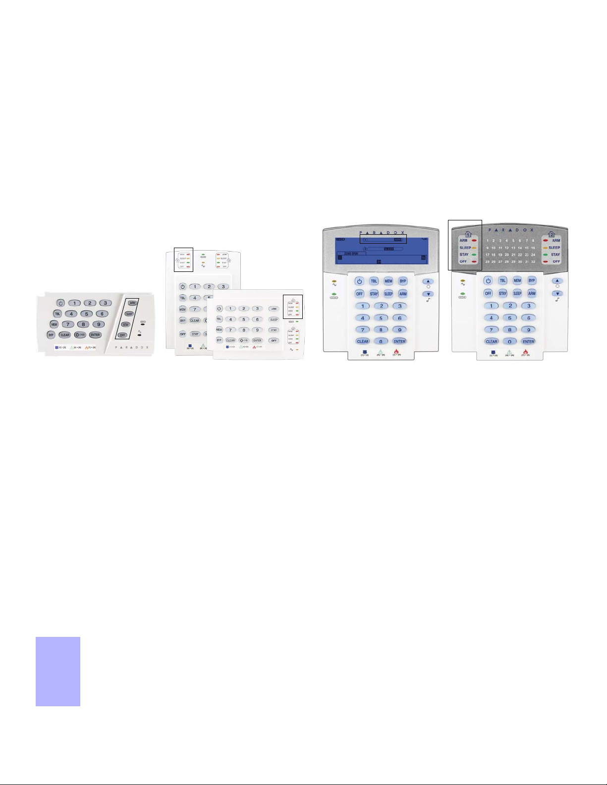
Entering Programming Mode
To access the Data Display Mode, press the [ENTER] key after entering a section and before entering any data.
The three keys / four LEDs as indicated below will begin to flash indicating that you are in the Data Display Mode.
Each time the [
ENTER] key is pressed, the keypad will display the next digit in the current section and will continue through all the
following sections one digit at a time without changing the programmed values. Not available for sections using the Multiple Feature
Select Method. Press the [
CLEAR] key at any time to exit the Data Display Mode.
K636 K10V/H
K32I
K32
1. Press [ENTER].
2. Enter your [
To modify codes, see System Codes on page 31.
3. Enter 3-digit [
4. Enter required [DATA].
WARNING: StayD Mode must be deactivated in order to enter programming mode. To deactivate StayD, press [
[OFF].
INSTALLER CODE] (default: 000000) or [MAINTENANCE CODE] (no default). [ARM] and [STAY] lights flash.
SECTION] you wish to program. [ARM] and [STAY] lights are ON.
Data Entry & Display
OFF] + [CODE] +
There are two methods that can be used to enter data when in programming mode: Single Digit Data Entry and Feature Select
Programming methods:
Single Digit Data Entry Method
After entering programming mode, some sections will require that you enter decimal values from 000 to 255. Other sections will require
that you enter hexadecimal values from 0 to F. The required data will be clearly indicated in this manual. When entering the final digit in a
section, the panel will automatically save and advance to the next section.
Feature Select Programming Method
After entering certain sections, eight options will be displayed where each option from [1] to [8] represents a specific feature. Press the
key corresponding to the desired option. This means the option is ON. Press the key again to remove the digit, thereby, turning OFF the
option. Press the [
next section.
CLEAR] key to set all eight options to OFF. When the options are set, press the [ENTER] key to save and advance to the
Important Settings and Modes
Section Description
[950] Reset all programmable sections to factory default values
[955] Clear bus module trouble (remove disconnected module from the bus)
[970] Download memory key into panel (see the Reference & Installation Manual)
[975] Upload panel into the memory key (see the Reference & Installation Manual)
[980] Display version number of the panel (see Viewing Version Numbers on page 3)
2 Programming Guide
Page 5
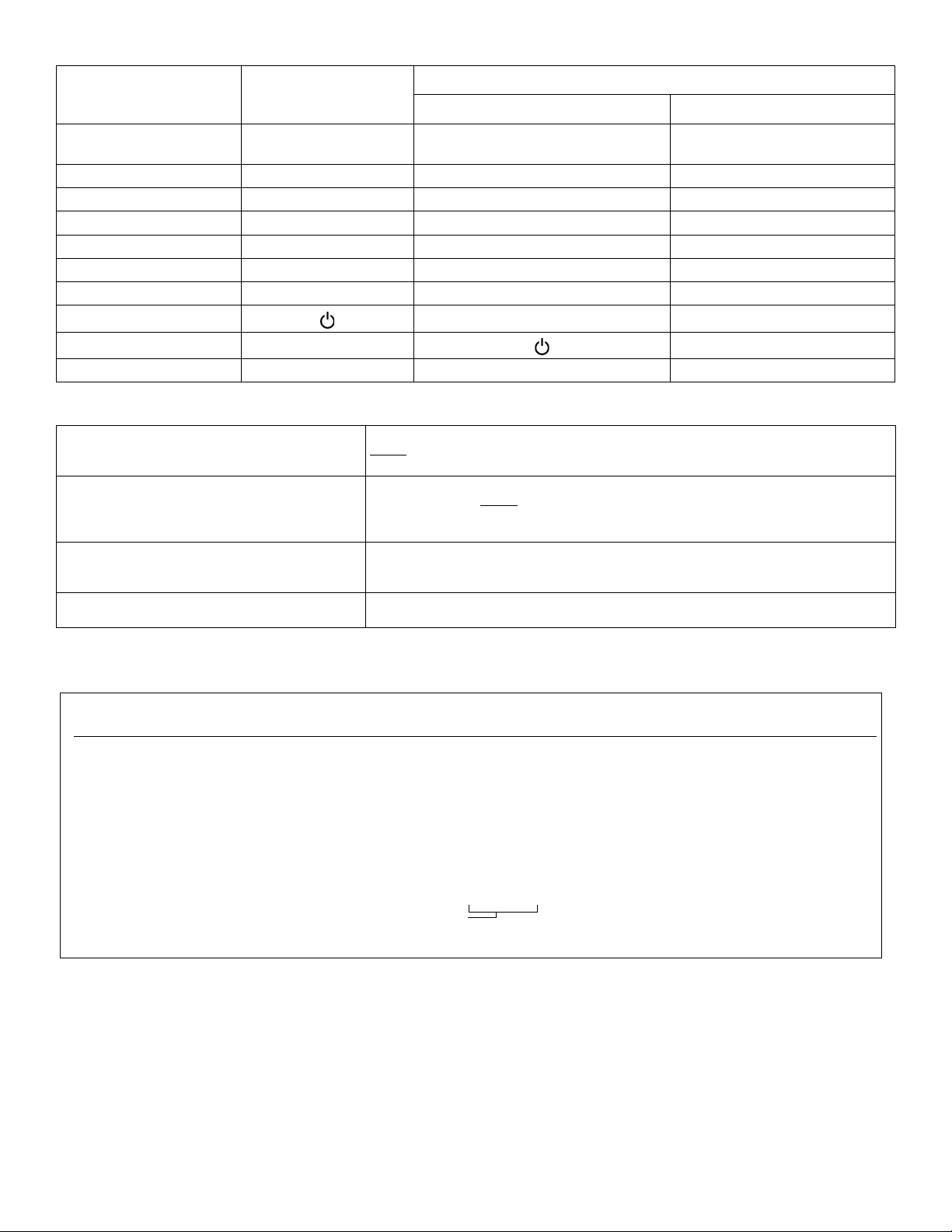
Decimal and Hexadecimal Values
Example:
Version 01.42.
Digits 1-4
NOTE: K10V/H / K636 keypad version numbers cannot be viewed.
Step Action Details When Viewing Keypad Version
1 Enter Viewing Mode:
-For panel version, Enter section [980].
-For keypad version, Enter Installer Programming,
then press and hold [
ARM].
The first digit is displayed
(usually “0”)
Digit 1 D [
ARM] is illuminated
2 Press [
ENTER] The second digit is displayed. Digit 2 D [SLEEP] is illuminated
3 Press [ENTER] The third digit is displayed. Digit 3 D [STAY] is illuminated
4 Press [
ENTER] The fourth digit is displayed. Digit 4 D [OFF] is illuminated
Value or Action What Do I Press?
Value 0 / Replace Current
SLEEP] Erase digit and remain in section Erase digit and remain in section
[
Digit with 0
Values 1 to 9 [1] to [9] Erase digit and remain in section Zone 1 to 9
A (hex only) [0] Keys 1 to 9 Zone 10
B (hex only) [
C (hex only) [
D (hex only) [
E (hex only) [
F (hex only)
Exit Without Saving [
Save Data (hex only) [
OFF] Key 0(10) Zone 11
BYP] OFF Zone 12
MEM] BYP Zone 13
TBL] MEM Zone 14
[]
CLEAR]
ENTER] ARM & STAY LED flash Advances to the next section
Codes and Panel Reset
Installer Code (Default: 0000 / 000000)
Maintenance Code (No Default)
System Master Code (Default: 1234 / 123456)
Panel Reset
What Do I See?
10-zone LED 32-zone LED
TBL Zone 15
A
[]
The Installer code is used to enter programming mode, which allows you to program everything
except
user codes. T o change the default code, go to section [397] on page 31 and refer to sec-
tion [701] option [1] on page 31.
The Maintenance code is used to enter programming mode, which allows you to
program everything except
[398], [815], [816], [817], [910], and [911]). To set the default code, go to section [398] on
page 31 and refer to section [701] option [1] on page 31.
The System Master code can use any arming method and can program user codes. To change
the default code, go to section [399] on page 31 and refer to section [701] option [1] on
page 31.
Before powering-up the panel, connect a wire from the zone 1 input to the PGM input. Power up
the panel and wait 6 seconds. Remove the wire and the panel will be reset to default.
for user codes and communication settings (sections [395], [397],
RM & STAY LED flash
Viewing Version Numbers
Esprit E55 / E65 3
Page 6

System Planning
Serial # Sticker Description
Keypad 1 / ZX8
/ ZX8SP
Keypad 2 / ZX8
/ ZX8SP
Keypad 3 / ZX8
/ ZX8SP
Keypad 4 / ZX8
/ ZX8SP
Keypad 5 / ZX8
/ ZX8SP
Keypad 6 / ZX8
/ ZX8SP
Path Zone
(Entry Point)
Path Zone Path Zone Path Zone
Keypad 7 / ZX8
/ ZX8SP
Keypad 8 / ZX8
/ ZX8SP
Keypad 9 / ZX8
/ ZX8SP
Keypad 10 / ZX8
/ ZX8SP
Keypad 11 / ZX8
/ ZX8SP
Keypad 12 / ZX8
/ ZX8SP
Keypad 13 / ZX8
/ ZX8SP
Keypad 14 / ZX8
/ ZX8SP
Keypad 15 / ZX8
/ ZX8SP
NOTE: Maximum of three ZX8 or ZX8SP modules.
4 Programming Guide
Page 7

Zone Programming
See Quick Menus on page 39
To program zone definitions, zone partitions and assign options:
Zone Recognition
When expanding zones via ZX8, up to 3 ZX8 modules can be added to the system and are identified by the ZX8 3-position jumpers +1,
+9 and +17.
E 55 No ATZ E 55 ATZ E65 No ATZ E65 ATZ
Zone 1: Panel Input 1 Zone 1: Panel Input 1A Zone 1: Panel Input 1 Zone 1: Panel Input 1A
Panel Zone 2: Panel Input 2 Zone 2: Panel Input 2A Zone 2: Panel Input 2 Zone 2: Panel Input 2A
Zone 3: Panel Input 3 Zone 3: Panel Input 3A Zone 3: Panel Input 3 Zone 3: Panel Input 3A
Zone 4: Panel Input 4 Panel Zone 4: Panel Input 4A Zone 4: Panel Input 4 Zone 4: Panel Input 4A
Zone 5: Input 1 Zone 5: Panel Input 1B Panel Zone 5: Panel Input 5 Zone 5: Panel Input 5A
Zone 6: Input 2 Zone 6: Panel Input 2B Zone 6: Panel Input 6 Zone 6: Panel Input 6A
ZX8 Zone 7: Input 3 Zone 7: Panel Input 3B Zone 7: Panel Input 7 Zone 7: Panel Input 7A
Jumper Zone 8: Input 4 Zone 8: Panel Input 4B Zone 8: Panel Input 8 Zone 8: Panel Input 8A
Panel + 1 Zone 9: Input 5 Zone 9: Input 1 Zone 9: Panel Input 9 Panel Zone 9: Panel Input 9A
Zone 10: Input 6 Zone 10: Input 2 Zone 10: Input 1 Zone 10: Panel Input 1B
Zone 11: Input 7 ZX8 Zone 11: Input 3 Zone 11: Input 2 Zone 11: Panel Input 2B
Zone 12: Input 8 Jumper Zone 12: Input 4 ZX8 Zone 12: Input 3 Zone 12: Panel Input 3B
Zone 13: Input 1 Panel + 1 Zone 13: Input 5 Jumper Zone 13: Input 4 Zone 13: Panel Input 4B
Zone 14: Input 2 Zone 14: Input 6 Panel + 1 Zone 14: Input 5 Zone 14: Panel Input 5B
ZX8 Zone 15: Input 3 Zone 15: Input 7 Zone 15: Input 6 Zone 15: Panel Input 6B
Jumper Zone 16: Input 4 Zone 16: Input 8 Zone 16: Input 7 Zone 16: Panel Input 7B
Panel + 9 Zone 17: Input 5 Zone 17: Input 1 Zone 17: Input 8 Zone 17: Panel Input 8B
Zone 18: Input 6 Zone 18: Input 2 Zone 18: Input 1 Zone 18: Panel Input 9B
Zone 19: Input 7 ZX8 Zone 19: Input 3 Zone 19: Input 2 Zone 19: Input 1
Zone 20: Input 8 Jumper Zone 20: Input 4 ZX8 Zone 20: Input 3 Zone 20: Input 2
Zone 21: Input 1 Panel + 9 Zone 21: Input 5 Jumper Zone 21: Input 4 ZX8 Zone 21: Input 3
Zone 22: Input 2 Zone 22: Input 6 Panel + 9 Zone 22: Input 5 Jumper Zone 22: Input 4
ZX8 Zone 23: Input 3 Zone 23: Input 7 Zone 23: Input 6 Panel + 1 Zone 23: Input 5
Jumper Zone 24: Input 4 Zone 24: Input 8 Zone 24: Input 7 Zone 24: Input 6
Panel + 17 Zone 25: Input 5 Zone 25: Input 1 Zone 25: Input 8 Zone 25: Input 7
Zone 26: Input 6 Zone 26: Input 2 Zone 26: Input 1 Zone 26: Input 8
Zone 27: Input 7 ZX8 Zone 27: Input 3 Zone 27: Input 2 Zone 27: Input 1
Zone 28: Input 8 Jumper Zone 28: Input 4 ZX8 Zone 28: Input 3 Zone 28: Input 2
Zone 29: N/A Panel + 17 Zone 29: Input 5 Jumper Zone 29: Input 4 ZX8 Zone 29: Input 3
Zone 30: N/A Zone 30:Input 6 Panel + 17 Zone 30: Input 5 Jumper Zone 30: Input 4
Zone 31: N/A Zone 31: Input 7 Zone 31: Input 6 Panel + 9 Zone 31: Input 5
Zone 32: N/A Zone 32: Input 8 Zone 32: Input 7 Zone 32: Input 6
Esprit E55 / E65 5
Page 8

Zone Definitions
[1]- N/A
[2]- N/A
[3]- N/A
[4] OFF = Disarm
ON = Disarm only if Stay/Sleep
armed
[5] = Arm only
[6] = Stay arming‡
[7] = Sleep arming‡
[8] = N/A
‡ Select only one. If all are off, keyswitch will regular arm.
[1] = Auto-zone Shutdown
[2] = Bypassable Zone
[3] = N/A
[4] [5]
OFF OFF Audible Alarm
OFF ON Pulsed Alarm
ON OFF Silent Alarm
ON ON Report Only
[6] = Intellizone
[7] = Delay alarm transmission
[8] = Force Zone
[1]- Partition 1†
[2]- Partition 2†
[3]- Both partitions†
†
When using a K636 keypad, only
partition 1 is available. To use both
partitions, use a K10V/H, K32, or K32I
keypad.
Table 2 Partition Assignment Table 3 Zone Options Table 4 Keyswitch Options
To program zone definitions, zone partitions and assign options:
Step Action Details
1 [
ENTER] + [INSTALLER CODE]
(default: 0000 / 000000)
[ARM] + [STAY] = flash. [MAINTENANCE CODE] may also be used.
2 Enter 3-digit zone you wish to program
[
ARM] + [STAY] = on (see table on page 7)
[001] to [032]
3 Enter a 2-digit zone definition 2 digits: 01 to 32 (see Table 1 below)
4 Assign Partition
By default, all zones are assigned to partition 1. (see Table 2)
[1], [2] or [3]
5 Select or deselect zone options using
buttons [1] to [8]
See Table 3 for zone options. ON = feature activated
See Table 4 for keyswitch options. OFF = feature deactivated
6 To save and proceed to the next zone,
ENTER]
press [
Table 1: Zone Definitions
Zone Definitions Stay Arm Sleep Arm Fully Arm Zone Definitions
00 = Zone Disabled (default) - - -
11 = Instant Fire†
01 = Entry Delay 1 Entry Delay 1 Entry Delay 1 Entry Delay 1 12 = Delayed Fire†
02 = Entry Delay 2 Entry Delay 2 Entry Delay 2 Entry Delay 2 13 = Instant Fire Silent†
03 = Entry Delay 1 (Full Arm)
Not Armed Not Armed Entry Delay 1 14 = Delayed Fire Silent†
04 = Entry Delay2 (Full Arm) Not Armed Not Armed Entry Delay 2 15 = 24Hr. Buzzer
05 = Follow Follow* Follow* Follow* 16 = 24Hr. Burglary
06 = Follow (Sleep/Full Arm)
Not Armed Follow* Follow 17 = 24Hr. Hold-up
07 = Follow (Full Arm) Not Armed Not Armed Follow 18 = 24Hr. Gas
08 = Instant Instant* Instant* Instant* 19 = 24Hr. Heat
09 = Instant (Sleep/Full Arm)
Not Armed Instant* Instant 20 = 24Hr. Water
10 = Instant (Full Arm) Not Armed Not Armed Instant 21 = 24Hr. Freeze
18 = 24Hr. Gas
* Flex-Instant = Zone will follow the delay at section [720], (default is 15 seconds / 0 = instant zone) 19 = 24Hr. Heat
** On-board hardwire control panel zones 1 to 4 (E55) or 1 to 9 (E65) 20 = 24Hr. Water
† Only on-board zones can be defined as fire zones 21 = 24Hr. Freeze
†† This alarm will follow the Panic 1 option (section [702], option [1]) 22 = 24hr. Panic††
23 = Follow No Pre-Alarm
NOTE: For more zone options, see sections [705] and [706] on page 8. 24 = Instant No Pre-Alarm
25 = Keyswitch Maintain**
26 = Keyswitch Momentary**
6 Programming Guide
Page 9

Partition
Section Zone*
[001] Zone 1: __________________________ _____/_____ ________ 12345678
[002] Zone 2: __________________________ _____/_____ ________ 12345678
[003] Zone 3: __________________________ _____/_____ ________ 12345678
[004] Zone 4: __________________________ _____/_____ ________ 12345678
[005] Zone 5: __________________________ _____/_____ ________ 12345678
[006] Zone 6: __________________________ _____/_____ ________ 12345678
[007] Zone 7: __________________________ _____/_____ ________ 12345678
[008] Zone 8: __________________________ _____/_____ ________ 12345678
[009] Zone 9: __________________________ _____/_____ ________ 12345678
[010] Zone 10: _________________________ _____/_____ ________ 12345678
[011] Zone 11: _________________________ _____/_____ ________ 12345678
[012] Zone 12: _________________________ _____/_____ ________ 12345678
[013] Zone 13: _________________________ _____/_____ ________ 12345678
Zone
Definition
(For a one-partition system,
use K636 keypads. For a
two-partition system, use
K10V/H, K32, or K32I
keypads.)
Zone Options
[014] Zone 14: _________________________ _____/_____ ________ 12345678
[015] Zone 15: _________________________ _____/_____ ________ 12345678
[016] Zone 16: _________________________ _____/_____ ________ 12345678
[017] Zone 17: _________________________ _____/_____ ________ 12345678
[018] Zone 18: _________________________ _____/_____ ________ 12345678
[019] Zone 19: _________________________ _____/_____ ________ 12345678
[020] Zone 20: _________________________ _____/_____ ________ 12345678
[021] Zone 21: _________________________ _____/_____ ________ 12345678
[022] Zone 22: _________________________ _____/_____ ________ 12345678
[023] Zone 23: _________________________ _____/_____ ________ 12345678
[024] Zone 24: _________________________ _____/_____ ________ 12345678
[025] Zone 25: _________________________ _____/_____ ________ 12345678
[026] Zone 26: _________________________ _____/_____ ________ 12345678
[027] Zone 27: _________________________ _____/_____ ________ 12345678
[028] Zone 28: _________________________ _____/_____ ________ 12345678
[029] Zone 29: _________________________ _____/_____ ________ 12345678
[030] Zone 30: _________________________ _____/_____ ________ 12345678
[031] Zone 31: _________________________ _____/_____ ________ 12345678
[032] Zone 32: _________________________ _____/_____ ________ 12345678
* See Zone Recognition on page 5.
NOTE: For keypad zone programming, see page 10.
Esprit E55 / E65 7
Page 10

[705] General Zone Options 1
Keypad Bus Tamper Recognition Options* Keypad / Bus Module Tamper Recognition Options*
[3] [4]
OFF OFF Disabled Disabled
OFF ON Trouble only Trouble only
ON OFF When disarmed:
TROUBLE ONLY
When armed: Follow zone’s alarm type
Trouble only
ON ON When di sa rm e d:
AUDIBLE ALARM
When armed: Follow zone’s alarm type
Audible alarm
* Tamper recognition of keypad / bus module only if section [700] option [7] is enabled.
Keypad Bus Module Supervision Options
[6] [7]
OFF OFF Disabled
OFF ON Trouble only
ON OFF When disarmed:
TROUBLE ONLY
When armed: Follow zone’s alarm type
ON ON When di sa rm e d:
AUDIBLE ALARM
When armed: Follow zone’s alarm type
Option OFF ON
[1]
[2]
A TZ zone dou blin g
A TZ wiring option s
Disabled N Enabled
Series N Parallel
[3]+[4] Tamper Recognition
[5]
Generate tamper on bypassed zone
N No Yes
[6]+[7] Supervision Options
[8] N/A N/A N/A
[706] General Zone Options 2
Option OFF ON
[1] N/A N/A N/A
[2]
EOL resistors
Disabled N Enabled
[3] N/A N/A N/A
[4]
[5]
[6]
ZX8 ID (Panel + 1) Input 1
ZX8 ID (Panel + 9) Input 1
ZX8 ID (Panel + 17) Input 1
Zone input N T amper input
Zone input N T amper input
Zone input N T amper input
Zone Timers
Section E55 E65 Data Description (Default 060)
[041] Zone 1 (Z1): (Z1): ____/____/____ (000 to 255) x 10ms Hardwi re Zone 1 Speed
[042] Zone 2 (Z2): (Z2): ____/____/____ (000 to 255) x 10ms Hardwire Zone 2 Speed
[043] Zone 3 (Z3): (Z3): ____/____/____ (000 to 255) x 10ms Hardwi re Zone 3 Speed
[044] Zone 4 (Z4): (Z4): ____/____/____ (000 to 255) x 10ms Hardwire Zone 4 Speed
[045] Zone 5 (Z1 with ATZ): (Z5): ____/____/____ (000 to 255) x 10ms Hardwire Zone 5 Speed
[046] Zone 6 (Z2 with A TZ): (Z6): ____/____/____ (000 to 255) x 10ms Hardwire Zone 6 Speed
[047] Zone 7 (Z3 with ATZ): ( Z7): ____/____/____ (000 to 255) x 10ms Hardwire Zone 7 Speed
[048] Zone 8 (Z4 with A TZ): (Z8): ____/____/____ (000 to 255) x 10ms Hardwire Zone 8 Speed
[049] Zone 9 N/A (Z9): ____/____/____ (000 to 255) x 10ms Hardwire Zone 9 Speed
[050] Zone 10 N/A (Z1 with ATZ): ____/____/____ (000 to 255) x 10ms Hardwire Zone 10 Speed
[051] Zone 11 N/A (Z2 with ATZ): ____/____/____ (000 to 255) x 10ms Hardwire Zone 11 S peed
[052] Zone 12 N/A (Z3 with ATZ): ____/____/____ (000 to 255) x 10ms Hardwire Zone 12 Speed
[053] Zone 13 N/A (Z4 with ATZ): ____/____/____ (000 to 255) x 10ms Hardwire Zone 13 Speed
8 Programming Guide
Page 11

Section E55 E65 Data Description (Default 060)
[054] Zone 14 N/A (Z5 with ATZ): ____/____/____ (000 to 255) x 10ms Hardwire Zone 14 Speed
[055] Zone 15 N/A (Z6 with ATZ): ____/____/____ (000 to 255) x 10ms Hardwire Zone 15 Speed
[056] Zone 16 N/A (Z7 with ATZ): ____/____/____ (000 to 255) x 10ms Hardwire Zone 16 Speed
NOTE: For zones 17 and 18 (ATZ on the E65,) the zone timer is set at 600ms.
Zone Report Codes (Default = FF)
[966] Clear Zone Report Codes
Option OFF ON
[1]
* Press [
[967] Reset Zone Report Codes
Option OFF ON
[1]
* Press [
Clear zone report codes*
ENTER] to reset the respective set of report codes to default before exiting the section.
Reset zone report codes to default*
ENTER] to reset the respective set of report codes to default before exiting the section.
N Disabled N Enabled
N Disabled N Enabled
Alarm
Section Alarm
[141] Zone 1: ___/_ __ ___/___ ___/___ ___/___ [157] Zone 17: ___/___ ___/___ ___/___ ___/___
[142] Zone 2: ___/___ ___/___ ___/___ ___/___ [158] Zone 18: ___/___ ___/___ ___/___ ___/___
[143] Zone 3: ___/_ __ ___/___ ___/___ ___/___ [159] Zone 19: ___/___ ___/___ ___/___ ___/___
[144] Zone 4: ___/___ ___/___ ___/___ ___/___ [160] Zone 20: ___/___ ___/___ ___/___ ___/___
[145] Zone 5: ___/___ ___/___ ___/___ ___/___ [161] Zone 21: ___/___ ___/___ ___/___ ___/___
[146] Zone 6: ___/___ ___/___ ___/___ ___/___ [162] Zone 22: ___/___ ___/___ ___/___ ___/___
[147] Zone 7: ___/___ ___/___ ___/___ ___/___ [163] Zone 23: ___/___ ___/___ ___/___ ___/___
[148] Zone 8: ___/___ ___/___ ___/___ ___/___ [164] Zone 24: ___/___ ___/___ ___/___ ___/___
[149] Zone 9: ___/_ __ ___/___ ___/___ ___/___ [165] Zone 25: ___/___ ___/___ ___/___ ___/___
[150] Zone 10: ___/___ ___/___ ___/___ ___/___ [166] Zone 26: ___/___ ___/___ ___/___ ___/___
[151] Zone 11: ___/___ ___/___ ___/___ ___/___ [167] Zone 27: ___/___ ___/___ ___/___ ___/___
[152] Zone 12: ___/___ ___/___ ___/___ ___/___ [168] Zone 28: ___/___ ___/___ ___/___ ___/___
[153] Zone 13: ___/___ ___/___ ___/___ ___/___ [169] Zone 29: ___/___ ___/___ ___/___ ___/___
[154] Zone 14: ___/___ ___/___ ___/___ ___/___ [170] Zone 30: ___/___ ___/___ ___/___ ___/___
[155] Zone 15: ___/___ ___/___ ___/___ ___/___ [171] Zone 31: ___/___ ___/___ ___/___ ___/___
[156] Zone 16: ___/___ ___/___ ___/___ ___/___ [172] Zone 32: ___/___ ___/___ ___/___ ___/___
Restore Tamper
Tamper
Restore Section Alarm
Alarm
Restore Tamper
Tamper
Restore
Esprit E55 / E65 9
Page 12

Keypad Programming
Keypad Zone Number Assignment
Step Action Details
1 [
2
3 [
Entry Point Zone Assignment (StayD)
Step Action Details
1 [
2 Press and hold [OFF] (3sec) [ARM] + [STAY] = on
3 [
4 [ENTER] Press [ENTER] to save and exit
ENTER] + [INSTALLER CODE]
(default: 0000 / 000000)
Press and hold (3sec)
ZONE NUMBER] + [ENTER]* K32LED / K32I = 2 digits: 01 to 32
ENTER] + [INSTALLER CODE]
(default: 0000 / 000000)
ZONE NUMBER]* K32LED / K32I = 2 digits: 01 to 32
[ARM] + [STAY] = flash. [MAINTENANCE CODE] may also be used.
[ARM] + [STAY] = on
K10V/H / K636 = 1 digit: 1 to 0(10) (can only assign zones 1-10)
* To erase a keypad zone number, press [CLEAR], then [ENTER].
[ARM] + [STAY] = flash.
K10V/H / K636 = 1 digit: 1 to 0(10) (can only assign zones 1-10)
* The first zone you program will be the designated entry point and will flash. Up to three
more path zones can be added; these zones will light up and stay lit.
Keypad Input/Output Configuration (K636 V2.0 and higher)
Step Action Details
1 [
2 Press and hold [
3 Option [1] ON = Output switches to ground following system arming (Blue wire 150mA max.).
4 Option [2] ON = Output N.C.
NOTE: When configuring as an output, you must first clear the keypad zone (if assigned).
[701] Keypad Options
Option OFF ON
[3]
[4]
[5]
[703] Keypad Options
Option OFF ON
[1]
[2]
[3]
[4]
ENTER] + [INSTALLER CODE]
(default: 0000 / 000000)
ARM] (3sec) [ARM] + [STAY] = on
Confidential mode
To exit confidential mode
Confidential mode timer
One-touch regular arming
One-touch stay arming
One-touch sleep arming
One-touch bypass programming
[ARM] + [STAY] = flash.
OFF = Input (Keypad zone input)
OFF = Output N.O.
N Disabled N Enabled
N Enter a code N Press a key
N 2 minutes N 5 seconds
N Disabled N Enabled
N Disabled N Enabled
N Disabled N Enabled
N Disabled N Enabled
10 Programming Guide
Page 13

[704] Keypad Options
[3] [4]
OFF OFF Regular
OFF ON Sleep
ON OFF Stay
[3] [4]
OFF OFF Regular
OFF ON Sleep
ON OFF Stay
Option OFF ON
[5]
[6]
[7] N o exit delay beep s a nd no bell sq uawk when stay/sleep
Keypad Locko ut
[716] ____/____/____ (000 to 255) minutes Keypad lockout delay (default 000)
[717] ____/____/____ (000 to 255) attempt before locking Keypad lockout counter (default 000)
Bell squawk when arm/disarm with a keypad
Beep on exit delay
arm
Data Description
N Disabled N Enabled
N Disabled N Enabled
N Disabled N Enabled
Partition Programming
NOTE: When using a K636 keypad, only partition 1 is available. To use both partitions, use a K10V/H, K32, or K32I keypad.
[700] Partitioning
Option OFF ON
[1]
[741] Partition 1 Options Bold = Default setting
Option OFF ON
[1] Auto-arm on time
[2] Auto-arm on no movement
Partitioning
Auto-arm arming mode
N Disabled N Enabled
Disabled N Enabled
Disabled N Enabled
N See Table N See Table
[3]& [4]
[5] Switch to stay arming if no zone entry delay is opened
[6]
[7]& [8] N/A N/A N/A
[742] Partition 2 Options
Option OFF ON
[1] Auto-arm on time
[2] Auto-arm on no movement
[3]& [4]
[5] Switch to stay arming if no entry delay is opened
[6]
Follow zones become entry delay 2 when delay zone is
bypassed
Auto-arm arming mode
Follow zones become entry delay 2 when delay zone is
bypassed
Disabled N Enabled
Disabled N Enabled
Disabled N Enabled
Disabled N Enabled
N See Table N See Table
Disabled N Enabled
Disabled N Enabled
Partition Timers
Refer to the Installer Quick Menu on page 39 for alternate entry/exit and bell cut-off timer programming.
Section Data Description
[745] ____/____/____ (000 to 255) seconds Partition 1 exit delay (default 060)
[746] ____/____/____ (000 to 255) seconds Partition 2 exit delay (default 060)
[747] ____/____/____ (000 to 255) minutes Partiti on 1 bell cut-off (default 004)
[748] ____/____/____ (000 to 255) minutes Parti tion 2 bell cut-off (default 004)
Esprit E55 / E65 11
Page 14

Section Data Description
See Quick Menus on page 39
[749] ____/____/____ (000 to 255) x 15 minutes Partition 1 no movement (default 000)
[750] ____/____/____ (000 to 255) x 15 minutes Partition 2 no movement (default 000)
Section Data Description
[761] ____/____:____/___ HH: MM Auto-arm on time Partition 1 (default 00:00)
[762] ____/____:____/____ HH: MM Auto-arm on time Partition 2 (default 00:00)
System Programming
[700] General System Options
Option OFF ON
[3]
[4]
[6]
[7]
[702] Panic Options
Option OFF ON
[1]
[2]
[3]
[4]
[5]
[6]
Audible trouble warning (except AC failure)
Audible trouble warning on AC failure
Exit delay termination
Tamper supervision on the bus module
Panic 1
Panic 2
Panic 3
Panic 1: Report only or audible alarm
Panic 2: Report only or audible alarm
Panic 3: Report only or audible alarm
N Disabled N Enabled
N Disabled N Enabled
N Disabled N Enabled
N Disabled N Enabled
Disabled N Enabled
Disabled N Enabled
Disabled N Enabled
Report only N Audible
Report only N Audible
Report only N Audible
[703] Arming/Disarming Options 1
Option OFF ON
[5]
[6]
[8]
[704] Arming/Disarming Options 2
Option OFF ON
[1]
[2]
[3]
Restrict arming on battery failure
Restrict arming on tamper failure (Zone + Bus Module)
Calling the VDMP3
Regular arming switches to force arming
Stay arming sw itches to st ay fo rce arming
Sleep arming switches to sleep force arming
Disabled N Enabled
Disabled N Enabled
N Disabled Enabled
N Disabled Enabled
N Disabled Enabled
N Disabled Enabled
System Timers
Section Data Description
[710] ____/____/____ (000 to 255) seconds Entry delay 1 (default 045)
[711] ____/____/____ (000 to 255) seconds Entry delay 2 (default 045)
[712] ____/____/____ (000 to 015) Auto zone shutdown counter (default 005)
[713] ____/____/____ (000 to 255) seconds Intellizone delay (default 048)
[714] ____/____/____ (000 to 255) minutes Recycle alarm delay (default 000)
[715] ____/____/____ (000 to 255) Recycle alarm counter (default 000)
[718] N/A N/A N/A
[719] ____/____/____ (000 to 255) days Closing delinquency delay (default 000)
[720] ____/____/____ (000 to 255) seconds For StayD: Flex-Instant delay (default 015)
[721] ____/____/____ (000 to 255) seconds For StayD: Re-arm delay (default 005)
12 Programming Guide
Page 15

Communication Programming
Telephone Line Monitoring (TLM) Options
[1] [2]
OFF OFF Disabled
OFF ON When disarmed: Trouble only
When armed: Trouble only
ON OFF When disarmed: Trouble only
When armed: Audible alarm
ON ON Silent alarms become Audible alarm
Auto-Test Report Transmission Options
[3] [4] Auto-Test Report Transmission Options
OFF OFF Transmit the test report code every time the days programmed in section [840] have elapsed at the time programmed in
section [850] (default).
OFF ON When disarmed: Transmit test report code every time the time programmed in section [852] has elapsed. When armed:
Transmit test report code every time the time programmed in section [851] has elapsed.
ON OFF The control panel will transmit the test report code every hour on the minute value programmed in section [850] (the last
two digits). Note that the first two digits of section [850] will be ignored. E.g. If 10:25 was programmed into section [850],
the test report code would be transmitted at the 25th minute of every hour, i.e. 11:25, 12:25, etc.
ON ON The test report code will be transmitted when any of the conditions of the second and third options listed above (options
[3] = OFF and [4] = ON / options [3] = ON and [4] = OFF) are met.
[800] Dialer Options
Option OFF ON
[1]+2]*
N See Table N See Table
[3]*
[4]
[5]*
[6]*
[7]*
[8]
Switch to pulse on 5th attempt
Alternate dial
Force dial (must be enabled to comply with TBR-21)
DTMF dialing
Pulse ratio
Reporting
Disabled N Enabled
Disabled N Enabled
N Disabled Enabled
N Disabled Enabled
N1:2 1:1.5
Dialer activated N Dialer deactivated
* E55 only
[801] Dialer Options
Option OFF ON
[1] Report system disarming
[2] Report zone restore
N Always After alarm
Bell cutoff N Zone closure
[3]+[4]
[5] Contact ID Override
N Disabled
N CID defaults / slow
format custom
[802] Event Call Direction Options 1
Option OFF ON
[1] Call tel. #1 for arm/disarm report codes
[2] Call tel. #2 for arm/disarm report codes
[3] Call pager for arm/disarm report codes
[5] Call tel. #1 for alarm/restore report codes
[6] Call tel. #2 for alarm/restore report codes
[7]
Esprit E55 / E65 13
Call pager for alarm/restore report codes
N Disabled Enabled
N Disabled Enabled
Disabled N Enabled
N Disabled Enabled
N Disabled Enabled
N Disabled Enabled
Page 16

[803] Event Call Direction Options 2
See Quick Menus on page 39
Option OFF ON
[1] Call tel. #1 for tamper/restore report codes
[2] Call tel. #2 for tamper/restore report codes
[3] Call pager for tamper/restore report codes
[5] Call tel. #1 for trouble/restore report codes
[6] Call tel. #2 for trouble/restore report codes
[7]
[804] Event Call Direction Options 3
Option OFF ON
[1] Call tel. #1 for special report codes
[2] Call tel. #2 for special report codes
[3] Call pager for special report codes
[5] Call personal tel. # on zone alarm (burglary/fire)
[6] Call personal tel. # on panic alarms
[7]
[8] Call personal tel. # on panel power trouble
Call pager for trouble/restore report codes
Call personal tel. # on parademic alarm
N Disabled Enabled
N Disabled Enabled
Disabled N Enabled
N Disabled Enabled
N Disabled Enabled
Disabled N Enabled
N Disabled Enabled
N Disabled Enabled
Disabled N Enabled
N Disabled Enabled
N Disabled Enabled
N Disabled Enabled
Disabled N Enabled
Communication Settings
Section Data Description
[810] ___/___ Reporting format
TEL1 TEL2
[811]
[812]
[815]
[816]
[817]
[818]
[819]
NOTE: To erase a phone number/numeric message, press the [SLEEP] key for each digit in the respective section.
____/____/____/____ Partition 1 Account number
____/____/____/____ Partition 2 Account number
___/___/___/___/___/___/___/___/___/___/___/___/___/___/___/___/___/___/___/___/___/___/___/___/___/___/
MONITORING STATION TELEPHONE NUMBER 1
___/___/___/___/___/___/___/___/___/___/___/___/___/___/___/___/___/___/___/___/___/___/___/___/___/___/
MONITORING STATION TELEPHONE NUMBER 2
___/___/___/___/___/___/___/___/___/___/___/___/___/___/___/___/___/___/___/___/___/___/___/___/___/___/
BACK UP TELEPHONE NUMBER
___/___/___/___/___/___/___/___/___/___/___/___/___/___/___/___/___/___/___/___/___/___/___/___/___/___/
PAGER TELEPHONE NUMBER
___/___/___/___/___/___/___/___/___/___/___/___/___/___/___/___/___/___/___/___/___/___/___/___/___/___/
NUMERIC MESSAGE SENT WITH PAGER REPORTING
0 = Ademco Slow
1 = Silent Knight Fast
2 = Sescoa
3 = Ademco Express
4 = Ademco Contact ID (default)
14 Programming Guide
Page 17

Special Keys for Telephone Numbers
Press Action or Value
OFF] *
[
[BYP] #
[MEM] switch from pulse to tone dialing or vice versa
[TBL] 4-second pause
[SLEEP] deletes current digit
[] inserts blank space
Communication Timers
Section Data Description
[830] ____/____/____ (000 to 255) x 2 seconds TLM fail delay (default 016)
[831] ____/____/____ (000 to 032) Maximum dialing attempts monitoring st a tion (default 008)
[832]* ____/____/____ ( 000 to 127) seconds Delay between dialing attempts* (default 020)
[833] ____/____/____ (000 to 255) second s Delay alarm tra nsmission (default 000)
[834] ____/____/____ (000 to 127) seconds Pager reporting delay (default 020)
[835] ____/____/____ (000 to 010) Pager reporting message repetition (default 003)
[836]* ____/____/____ (000 to 127) seconds Personal reporting delay* (default 005)
[837]* ____/____/____ (000 to 010) Personal reporting message repetition* (default 003)
[838] ____/____/____ (000 to 255) seconds Recent closing delay (default 000)
[839] ____/____/____ (000 to 255) minutes Power failure report delay (default 015)
[840] ____/____/____ (000 to 255) days Auto test report (default 000) (see section [801] options [3]
and [4] on page page 13)
* This section applies to the Plug-In Voice Dialer when using a VDMP3.
[850] ____/____/____/____ HH: MM Auto test report time of day (default 00:00) (see section [801]
options [3] and [4] on page page 13)
[851] ____/____/____ (000 to 255) x 1 minute Armed report delay (default 005)
[852] ____/____/____ (000 to 255) x 1 minute Disarmed report delay (default 060)
[901]* ____/____/____ (000 to 255) rings Number of rings* (default 008)
[902]* ____/____/____ (000 to 255) seconds Answering machine override delay* (default 030)
* This section applies to the Plug-In Voice Dialer when using a VDMP3 (E55 only).
Communication Report Codes
[966] Clear Communication Report Codes
Option OFF ON
[6]
* Press [
[967] Reset Communication Report Codes
Option OFF ON
[6]
* Press [
[879] ____/____ GSM RF jam [880] __ __/____ N/A
[884] ____/____ Report code for GSM lost communication with panel
Clear report code for GSM lost communication with panel*
ENTER] to reset the respective set of report codes to default before exiting the section.
Reset report code for GSM lost communication with panel*
ENTER] to reset the respective set of report codes to default before exiting the section.
____/____ GSM no service ____/____ IP100 no service*
____/____ GSM module supervision lost ____/____ IP100 supervision lost*
____/____ GPRS receiver fail to communicate* ____/____ IP receiver fail to communicate*
____/____ N/A
____/____ N/A * E65 panels only
____/____ N/A
N Disabled N Enabled
N Disabled N Enabled
Esprit E55 / E65 15
Page 18

Communication Restore Report Codes
[881] ____/____ GSM RF jam [882] ____/____ N/A
____/____ GSM no service ____/____ IP100 no service*
____/____ GSM module supervision lost ____/____ IP100 supervision lost*
____/____ GPRS receiver fail to commu nicat e* ____/____ IP receiver fail to communicate*
* E65 panels only
VDMP3 Options
[703] Calling the VDMP3
Option OFF ON
[8]
Calling the VDMP3
N Disabled N Enabled
Section Data Description
[841] ____/____/____ (000 to 032) Maximum voice dialing attempts - VDMP3 (default 008)
* This section applies to the Plug-In Voice Dialer when using a VDMP3.
NOTE: For more VDMP3 options, see Communication Timers on page 15.
WinLoad / IP100 / PCS100 Programming
[900] WinLoad Options
OFF ON
[1] Call back
[2] Automatic event buffer transmission
N Disabled N Enabled
N Disabled N Enabled
[910] ____/____/____/____ Panel ID
[911] ____/____/____/____ PC password
NOTE: For increased communication security, change
the default Panel ID and PC password.
[915] ___/___/___/___/___/___/___/___/___/___/___/___/___/___/___/___/___/___/___/___/___/
PC TELEPHONE NUMBER
WinLoad / PCS100 Connection Settings
[780] ___/___/___/___/___/___/___/___/___/___/___/___/___/___/___/___/
SMS SITE NAME
[920] ____/____/____/____/____
PORT (DEFAULT = 10000)
[921]* ___/___/___/___/___/___/___/___/___/___/___/___/___/___/___/___/
ACCESS POINT NAME (APN) PART 1 (E.G. INTERNET.COM)
[922]* ___/___/___/___/___/___/___/___/___/___/___/___/___/___/___/___/
ACCESS POINT NAME (APN) PART 2
[923]* ___/___/___/___/___/___/___/___/___/___/___/___/___/___/___/___/
USER NAME PART 1
[924]* ___/___/___/___/___/___/___/___/___/___/___/___/___/___/___/___/
USER NAME PART 2
[925]* ___/___/___/___/___/___/___/___/___/___/___/___/___/___/___/___/
PASSWORD PART 1
[926]* ___/___/___/___/___/___/___/___/___/___/___/___/___/___/___/___/
PASSWORD PART 2
[927]* ___/___/___/___/___/___/___/___/___/___/___/___/___/___/___/___/
INSTALLER SOFTWARE PASSWORD (WINLOAD) (DEFAULT = ADMIN)
* Must be configured through WinLoad
Refer to the Installer Quick Menu on page 40 for alternate programming of PC phone number, panel ID, and PC password.
16 Programming Guide
Page 19

PCS100 Programming
GSM Reporting*
[1] [2] Primary Backup
OFF OFF
Landline Landline
OFF ON
Landline GSM
ON OFF
GSM Landline
ON ON
GSM GSM
* Options [1] and [2] are only available on the
E55 control panel. The E65 will only
communicate via GSM.
GSM No Service Trouble Feedback
[5] [6]
OFF OFF
Disabled
OFF ON
When disarmed: Trouble only
When armed: Trouble only
ON OFF
When disarmed: Trouble only
When armed: Audible alarm
ON ON
Silent alarm becomes audible alarm
IP/GPRS No Service Trouble Feedback
[5] [6]
OFF OFF
Disabled
OFF ON
When disarmed: Trouble only
When armed: Trouble only
ON OFF
When disarmed: Trouble only
When armed: Audible alarm
ON ON
Silent alarm becomes audible alarm
[805] GSM Options
Option
[1] & [2]
[3] & [4] Future use
[5] & [6]
[7] Future use
[8] GSM RF jamming supervision
OFF ON
N Disabled Enabled
PCS100 (GSM) Settings
Section Data Description
[855] ___/___/___ (000 to 255) x 2 seconds GSM no service timer (default 016)
[856] ___/___/___ (000 to 255) SMS language (default 000)
Table 5: SMS Language ID
Language ID Language ID Language ID Language ID
English 000 Portuguese 006 Croatian 012 Slovak 018
French 001 German 007 Greek 013 Chinese 019
Spanish 002 Turkish 008 Hebrew 014 Serbian 020
Italian 003 Hungarian 009 Russian 015 Future use 021 to 255
Swedish 004 Czech 010 Bulgarian 016
Polish 005 Dutch 011 Romanian 017
IP100 / PCS100 (GPRS) Options
[806] IP/GPRS Options (E65 panels only)
Option
[5] & [6]
OFF ON
[7] Use dialer reporting
[8]
Esprit E55 / E65 17
Enable IP/GPRS reporting
N As IP/GPRS reporting backup N In addition to IP/GPRS reporting
N Disabled N Enabled
Page 20

IP / GPRS Reporting Account Settings (E65 panels only)
(see Table 6 on page 19)
(see Table 6 on page 19)
IP Account Numbers
[918] ___/___/___/___
IP ACCOUNT PARTITION 1 (E.G. 1234)
[919] ____/___/___/___
IP ACCOUNT PARTITION 2 (E.G. 1234)
IP Receiver 1 Configuration
[929] ___/___/___ . ___/___/___ . ___/___/___ . ___/___/___
IP ADDRESS WAN1 (E.G. 100.100.100.100) NOTE: FOR 1 OR 2 DIGIT NUMBERS, ADD “0”S BEFORE THE FIRST DIGIT
[930] ___/___/___/___/___
IP PORT WAN1 (E.G. 10000)
[931] ___/___/___ . ___/___/___ . ___/___/___ . ___/___/___
IP ADDRESS WAN2
[932] ___/___/___/___/___
IP PORT WAN2
[933] ___/___/___/___/___/___/___/___/___/___/___/___/___/___/___/___
IP PASSWORD (E.G. 123456)
[934] ___/___
IP PROFILE (E.G. 01)
[935] IP RECEIVER STATUS VIEW STATUS / TO REGISTER, PRESS [ARM]
IP Receiver 2 Configuration
[936] ___/___/___ . ___/___/___ . ___/___/___ . ___/___/___
IP ADDRESS WAN1 (E.G. 100.100.100.100)
[937] ___/___/___/___/___
IP PORT WAN1 (E.G. 10000)
[938] ___/___/___ . ___/___/___ . ___/___/___ . ___/___/___
IP ADDRESS WAN2
[939] ___/___/___/___/___
IP PORT WAN2
[940] ___/___/___/___/___/___/___/___/___/___/___/___/___/___/___/___
IP PASSWORD (E.G. 123456)
[941] ___/___
IP PROFILE (E.G. 01)
[942] IP RECEIVER STATUS
STATUS / TO REGISTER, PRESS [ARM]
VIEW
IP Receiver Backup Configuration
[943] ___/___/___ . ___/___/___ . ___/___/___ . ___/___/___
IP ADDRESS WAN1 (E.G. 100.100.100.100)
[944] ___/___/___/___/___
IP PORT WAN1 (E.G. 10000)
[945] ___/___/___ . ___/___/___ . ___/___/___ . ___/___/___
IP ADDRESS WAN2
[946] ___/___/___/___/___
IP PORT WAN2
[947] ___/___/___/___/___/___/___/___/___/___/___/___/___/___/___/___
IP PASSWORD (E.G. 123456)
18 Programming Guide
Page 21

[948] ___/___
(see Table 6 on page 19)
See Quick Menus on page 41
IP PROFILE (E.G. 01)
[949] IP RECEIVER STATUS
VIEW
STATUS / TO REGISTER, PRESS [ARM]
Table 6: IP/GPRS Registration Status (E65 panels only)
Main Menu Trouble Sub-Menu Trouble Menu
[1] IP/GPRS module registration status [1] OFF = Unregistered
[1] Slow Flash = Registering...
[1] ON = Registration OK
[2] IP/GPRS module error [7] No IP/GPRS module
[8] Ethernet cable unplugged/GSM no service
[9] No IP address acquired by module/GPRS network trouble
[3] IP/GPRS programming error [7] No IP add ress (not programmed)
[8] No IP port (not programmed)
[9] No IP account (not programmed)
[10] No Access point name (not programmed - GPRS only)
[4] IP/GPRS registration error [7] Cannot connect
[8] Invalid profile
[9] Invalid format
[10] Account already registered under another MAC address
Register module When all troubles are cleared, press [
ARM] to register module.
Programmable Output Programming
Programmable Output Activation/Deactivation Events
Section Event Group # Sub-Group #
[220] PGM 1: Activation Event (____/____) (____/____) (____/____) 00/00/00
[221] Deactivation Event (____/____) (____/____) (____/____) 00/00/00
[222] PGM 2: Activation Event (____/____) (____/____) (____/____) 00/00/00
[223] Deactivation Event (____/____) (____/____) (____/____) 00/00/00
[224] PGM 3: Activation Event (____/____) (____/____) (____/____) 00/00/00
[225] Deactivation Event (____/____) (____/____) (____/____) 00/00/00
[230] PGM 6: Activation Event (____/____) (____/____) (____/____) 00/00/00
[231] Deactivation Event (____/____) (____/____) (____/____) 00/00/00
[232] PGM 7: Activation Event (____/____) (____/____) (____/____) 00/00/00
[233] Deactivation Event (____/____) (____/____) (____/____) 00/00/00
[234] PGM 8: Activation Event (____/____) (____/____) (____/____) 00/00/00
[235] Deactivation Event (____/____) (____/____) (____/____) 00/00/00
[236] PGM 9: Activation Event (____/____) (____/____) (____/____) 00/00/00
[237] Deactivation Event (____/____) (____/____) (____/____) 00/00/00
[238] PGM 10: Activation Event (____/____) (____/____) (____/____) 00/00/00
[239] Deactivation Event (____/____) (____/____) (____/____) 00/00/00
[240] PGM 11: Activation Event (____/____) (____/____) (____/____) 00/00/00
[241] Deactivation Event (____/____) (____/____) (____/____) 00/00/00
[242] PGM 12: Activation Event (____/____) (____/____) (____/____) 00/00/00
[243] Deactivation Event (____/____) (____/____) (____/____) 00/00/00
NOTE: PGM 1 (for E55/E65) PGM 2 and 3 (for E65 only)
PGMs 6 to 8 are only available when using an ZX8 or ZX8SP Hardwired Zone Expansion module.
PGMs 9 to 12 are only available when using a PGM4 4-PGM Expansion module.
If a PGM Delay is programmed, the deactivation event can be used as a second activation event (see sections
[281] to [292] on page 24).
Partition # (99 for any
partitions)
Default
Esprit E55 / E65 19
Page 22

Event Description
Event Group # Sub-group #
00 = Zone OK 01 to 32 = Zone number
99 = Any zone number01 = Zone open
02 = Partition status 00 to 01= N/A
02 = Silent alarm
03 = Buzzer alarm
04 = Steady alarm
05 = Pulsed alarm
06 = Strobe
07 = Alarm stopped
08 = Squawk ON (Partition 1 only)
09 = Squawk OFF (Partition 1 only)
10 = Ground start (Partition 1 only)
11 = Di sarm p artition
12 = Arm partition
13 = Entry delay started
14 = Exit delay started
15 = Pre-alarm delay
99 = Any partition status event
03 = Bell status (Partition 1 only) 00 = Bell OFF
01 = Bell ON
02 = Bell squawk arm
03 = Bell squawk disarm
99 = Any bell status event
06 = Non-reportable event 00 = Telephone line trouble
ENTER] / [CLEAR] / [ ] key was pressed (Partition 1 only)
01 = [
02 = N/A
03 = Arm in stay mode
04 = Arm in sleep mode
05 = Arm in force mode
06 = Full arm when armed in stay mode
07 = PC fail to communicate (Partition 1 only)
08 = Utility Key 1 pressed (keys [1] and [2]) (Partition 1 only)
09 = Utility Key 2 pressed (keys [4] and [5]) (Partition 1 only)
10 = Utility Key 3 pressed (keys [7] and [8]) (Partition 1 only)
11 = Uti lity Key 4 pressed (ke ys [2] and [3]) (Partiti on 1 only)
12 = Utility Key 5 pressed (keys [5] and [6]) (Partition 1 only)
13 = Utility Key 6 pressed (keys [8] and [9]) (Partition 1 only)
14 = Tamper generated alarm
15 = Supervision loss generated alarm
16 = N/A
17 = N/A
18 = N/A
19 = N/A
20 = Full arm when armed in sleep mode
21 = Firmware upgrade (Partition 1 only) (non-PGM event)
22 = No SIM card on GSM module
23 = StayD mode activa ted
24 = StayD mode dea ctivated
25 = IP Registration St atus (E65 p anels only)
26 = GPRS Registration St atus (E65 p anels only)
99 = Any non-reportable event
14 = Bypass programming 01 to 32 = User number
99 = Any user number15 = User code activated output (Partition 1 only)
16 = N/A 01 to 32 = Zone number
99 = Any zone number17 = Delay zone alarm transmission
18 to 23 = N/A
24 = Fire Delay started 01 to 32 = Zone number
99 = Any zone number
25 = N/A
20 Programming Guide
Page 23

Event Group # Sub-group #
26 = Software Access (VDMP3, IP100, NEware, WinLoad) 00 = Non-valid source ID
01 = WinLoad direct
02 = WinLoad through IP module
03 = WinLoad through GSM module
04 = WinLoad through modem
05 = NEware direct
06 = NEware through IP module
07 = NEware through GSM module
08 = NEware through modem
09 = IP100 direct
10 = VDMP3 direct
1 1 = Voice through GSM module
12 = Remote access
13 = SMS through GSM module
99 = Any software access
27 = Bus module event 00 = A bus module was added
01 = A bus module was removed
99 = Any Bus module event
28 = StayD pass acknowledged 01 to 32 = Zone number
99 = Any zone number
29 = Arming with user 01 to 32 = User number
99 = Any user number
30 = Special arming 00 = Auto-arming (on time/no movement)
01 = Late to close
02 = No movement arming
03 = Partial arming
04 = Quick arming
05 = Arming through WinLoad
06 = Arming with keyswitch
99 = Any special arming
31 = Disarming with user 01 to 32 = User number
99 = Any user number32 = Disarming after alarm with user
33 = Alarm cancelled with user
34 = Special disarming 00 = Auto-arm cancelled (on time/no movement)
01 = Disarming through WinLoad
02 = Disarming through WinLoad after alarm
03 = Alarm cancelled through WinLoad
04 = N/A
05 = Disarm with keyswitch
06 = Disarm with keyswitch after an alarm
07 = Alarm cancelled with keyswitch
99 = Any special disarming
35 = Zone bypassed 01 to 32 = Zone number
99 = Any zone number36 = Zone in alarm
37 = Fire alarm
38 = Zone alarm restore
39 = Fire alarm restore
40 = Special alarm 00 = Panic non-medical emergency
01 = Panic medical (this panic alarm is not UL approved)
02 = Panic fire
03 = Recent closing
04 = Global shutdown
05 = Duress alarm
06 = Keypad lockout (Partition 1 only)
99 = Any special alarm event
41 = Zone shutdown 01 to 32 = Zone number
99 = Any zone number42 = Zone tampered
43 = Zone tamper restore
Esprit E55 / E65 21
Page 24

Event Group # Sub-group #
44 = New trouble
(Partition 1 only except sub-group 07 = both partitions)
00 = N/A
01 = AC failure
02 = Battery failure
03 = Auxiliary current overload
04 = Bell current overload
05 = Bell disconnected
06 = Clock loss
07 = Fire loop trouble
08 = Fail to communicate to monitoring station telephone #1
09 = Fail to communicate to monitoring station telephone #2
10 = Fail to communicate to pager report
11 = Fail to communicate to voice report
13 = GSM RF jamming
14 = GSM no service
15 = GSM supervision lost
16 = Fail To Communicate IP Receiver 1 (GPRS) (E65 panels only)
17 = Fail To Communicate IP Receiver 2 (GPRS) (E65 panels only)
18 = IP Module No Service (E65 panels only)
19 = IP Module Supervision Loss (E65 panels only)
20 = Fail To Communicate IP Receiver 1 (IP) (E65 panels only)
21 = Fail To Communicate IP Receiver 2 (IP) (E65 panels only)
99 = Any new trouble event
45 = Trouble restored 00 = Telephone line restored
01 = AC failure restore
02 = Battery failure restore
03 = Auxiliary current overload restore
04 = Bell current overload restore
05 = Bell disconnected restore
06 = Clock loss restore
07 = Fire loop trouble restore
08 = FTC central 1 restored
09 = FTC central 2 restored
10 = FTC pager restored
11 = FTC voice restored
13 = GSM jamming restored
14 = GSM no service restore
15 = GSM supervision lost restore
16 = Fail To Communicate restore IP Receiver 1 (GPRS) (E65 only)
17 = Fail To Communicate restore IP Receiver 2 (GPRS) (E65 only)
18 = IP Module No Service restore (E65 panels only)
19 = IP Module Supervision loss restore (E65 only)
20 = Fail To Communicate restore IP Receiver 1 (IP) (E65 only)
21 = Fail To Communicate restore IP Receiver 2 (IP) (E65 only)
99 = Any trouble restored event
46 = Bus / EBus module new trouble
(Partition 1 only)
00 = Bus / EBus module communication fault
01 = Tamper trouble
02 = Power fail
03 = Battery failure
99 = Any bus module new trouble event
47 = Bus / EBus module trouble restored
(Partition 1 only)
00 = Bus / EBus module communication fault restore
01 = Tamper trouble restore
02 = Power fail
03 = Battery failure
99 = Any bus module trouble restored event
48 = Special (Partition 1 only) 00 = System power up
01 = Reporting test
02 = Software log on
03 = Software log off
04 = Installer in programming mode
05 = Installer exited programming mode
06 = Maintenance in programming mode
07 = Maintenance exited programming mode
08 = Closing delinquency delay elapsed
99 = Any special event
22 Programming Guide
Page 25

Event Group # Sub-group #
49 to 56 = N/A
58 = Zone forced 01 to 32 = Zone number
99 = Any zone number59 = Zone included
64 = System Status 00 = Follow Arm LED status*:
1. PGM pulse fast in alarm
2. PGM pulse fast in exit delay below 10 sec.
3. PGM pulse slow in exit delay over 10 sec.
4. PGM steady ON if armed
5. PGM OFF if disarmed
* On-board PGM only: This event can be assigned to an y parti tion. If
assigned to both partitions, the PGM event will follow the priority of
the list above, with #1 being the highest priority.
Programmable Output Options
PGM 1
[261]
Option OFF ON OFF ON OFF ON
PGM 2
[262]
PGM 3
[263]
PGM 4-5
[264]-[265]
future use
PGM Base Time
[1]
Off=Sec, On=Min
[2] PGM State Off=N.O., On=N.C.
[3] N/A N/A N/A N/A N/A N/A N/A
PGM Activation Mode
[4]
Off=Steady, On=Pulse
PGM Pulse once every 30
[5]*
seconds if armed*
[6]* PGM Pulse on any alarm*
PGM Pulse on any alarm -
[7]
Off= Partition 1, On= Partition 2
Voltage Output (E65 PGMs only)
[8]
Off= Negative Trigger (0V)
On= Positive Trigger (12V)
Option OFF ON OFF ON OFF ON OFF ON OFF ON OFF ON OFF ON
PGM Base Time
[1]
Off=Sec, On=Min
[2] PGM State Off=N.O., On=N.C.
[3] N/A N/A N/A N/A N/A N/A N/A N/A N/A N/A N/A N/A N/A N/A N/A
PGM Activation Mode
[4]
Off=Steady, On=Pulse
PGM Pulse once every 30
[5]*
seconds if armed*
[6]* PGM Pulse on any alarm*
PGM Pulse on any alarm -
[7]
Off= Partition 1, On= Partition 2
[8] N/A -------------* If options 5 or 6 are enabled, The following Programmable Output Activation/Deactivation Events do not apply: [22 0 ], [230], [ 232], and [234].
N N N
N N N
N N N
N N N
N N N
N N N
N N N
ZX8 +1 ZX8 +9 ZX8 +17 PGM4
PGM 6
[266]
PGM 7
[267]
PGM 8
[268]
PGM 9
[269]
PGM 10
[270]
PGM 11
[271]
PGM 12
[272]
N N N N N N N
N N N N N N N
N N N N N N N
N N N N N N N
N N N N N N N
N N N N N N N
NOTE: PGM 1 (E55/E65) PGMs 2 and 3 (E65 only)
PGMs 6 to 8 are only available when using an ZX8 or ZX8SP Hardwi red Zone Expansion module.
PGMs 9 to 12 are only available when using a PGM4 4-PGM Expansion module.
PGM cannot exceed 150mA (current limit).
Esprit E55 / E65 23
Page 26

Programmable Output Delays & Recognition
Section Data Default = 005
[281] PGM 1: (E55/E65 onboard) ___/___/___ (000 to 255 x 1 sec./mins.)
[282] PGM 2: (E65 onboard) ___/___/___ (000 to 255 x 1 sec./mins.)
[283] PGM 3: (E65 onboard) ___/___/___ (000 to 255 x 1 sec./mins.)
[286] PGM 6: (ZX8 ID =+1) ___/___/___ (000 to 255 x 1 sec./mins.)
[287] PGM 7: (ZX8 ID =+9) ___/___/___ (000 to 255 x 1 sec./mins.)
[288] PGM 8: (ZX8 ID =+17) ___/___/___ (000 to 255 x 1 sec./mins.)
[289] PGM 9: (PGM4 output 1) ___/___/___ (000 to 255 x 1 sec./mins.)
[290] PGM 10: (PGM4 output 2) ___/_ __/___ (000 to 255 x 1 sec./mins.)
[291] PGM 11: (PGM4 output 3) ___/_ __/___ (000 to 255 x 1 sec./mins.)
[292] PGM 12: (PGM4 output 4) ___/_ __/___ (000 to 255 x 1 sec./mins.)
System Report Codes
Entering Report Codes
Ademco Slow, Silent Knight, SESCOA, and Ademco Express Formats:
Enter the desired 2-digit hex value (00-FF).
Ademco “Programmable” Format:
Enter the desired 2-digit hex values from the “Ademco Report Code List - Programmable” (see page 26). Also Note that entering FF will
set the report code to the “Automatic Report Code List” (see page 28).
Ademco “All Codes” Format:
The control panel automatically generates report codes from the “Ademco Report Code List - All Codes” (see page 26).
Refer to Decimal and Hexadecimal Values on page 3.
Clear System Report Codes
[966] Clear Report Codes
Option OFF ON
[3]
[4]
[5]
* Press [
Clear arm/disarm/alarm report codes*
Clear trouble report codes*
Clear system special report codes*
ENTER] to reset the respective set of report codes to default before exiting the section.
N Disabled N Enabled
N Disabled N Enabled
N Disabled N Enabled
Reset System Report Codes
[967] Reset Report Codes
Option OFF ON
[3]
[4]
[5]
* Enable all options you want to reset to default. Press [
default before exiting the section.
Special Arming Report Codes
Section Data Description Section Data Description
[860] _____/_____ Auto-arming [861] _____/_____ Quick arming
Reset arm/disarm/alarm report codes to default*
Reset trouble report codes to default*
Reset system special report codes to default*
ENTER] to reset the respective set of report codes to
N Disabled N Enabled
N Disabled N Enabled
N Disabled N Enabled
(Default = FF)
_____/_____ Late to close _____/_____ Arming via PC
_____/_____ No movement _____/_____ Arming with keyswitch
_____/_____ Partial arming _____/_____ N/A
24 Programming Guide
Page 27

Special Disarming Report Codes (Default = FF)
Section Data Description
[862] _____/_____ Cancel auto-arm
_____/_____ Disarming via PC
_____/_____ Cancel alarm with user or WinLoad
_____/_____ Cancel parademic
Special Alarm Report Codes (Default = FF)
Section Data Description Section Data Description
[863] _____/_____ Emergency panic [864] _____/_____ Zone shutdown
_____/_____ Auxiliary panic _____/_____ Duress
_____/_____ Fire panic _____/_____ Keypad lockout
_____/_____ Recent closing _____/_____ N/A
System Trouble Report Codes (Default = FF)
Section Data Description Section Data Description
[865] ____/____ N/A [868] ____/____ Module power fail
____/____ AC failure ____/____ Module low/no battery
____/____ Battery failure ____/____ N/A
____/____ Auxiliary supply ____/____ N/A
[866] ____/____ Bell output overload
____/____ Bell output disconnect
____/____ Timer loss
____/____ N/A
[867] ____/____ Fail to communicate
____/____ N/A
____/____ Module lost
____/____ Module tamper
System Trouble Restore Report Codes (Default = FF)
Section Data Description Section Data Description
[870] ____/____ TLM [873] ____/____ Module power fail
____/____ AC failure ____/____ N/A
____/____ Battery failure ____/____ N/A
____/____ Auxiliary supply ____/____ N/A
[871] ____/____ Bell output overload
____/____ Bell output disconnect
____/____ Timer loss
____/____ N/A
[872] ____/____ Fail to communicate
____/____ N/A
____/____ Module lost
____/____ Module tamper
System Special Report Codes (Default = FF)
Section Data Description Section Data Description
[875] ____/____ Cold start [876] ____/____ Installer in
Esprit E55 / E65 25
Page 28

Section Data Description Section Data Description
____/____ Test report ____/____ Installer out
____/____ N/A ____/____ Closing Delinquency
____/____ WinLoad out ____/____ N/A
[878] _____ /_____ Disarm with keyswitch
Disarm with keyswitch after
_____/_____
alarm
Alarm cancelled with key-
_____/_____
switch
_____/_____ N/A
NOTE: For reporting code format instructions, see page 24.
NOTE: Refer to Decimal and Hexadecimal Values on page 3.
Ademco Contact ID Report Codes
CID# Reporting Code Programming
Value
Medical Alarms - 100 151 Gas detected 26 327 Notification appliance chk. #44E
100 Medical alarm 01 152 Refrigeration 27 System Peripheral Troubles - 330 and 340
101 Pendant transmitter 02 153 Loss of heat 28
102 Fail to report in 03 154 Water leakage 29
Fire Alarms - 110 155 Foil break 2A 332 Polling loop sho rt 51
110 Fire alarm 04 156 Day trouble 2B 333 Expansion module failure 52
111 Smoke 05 157 Low bottled gas level 2C
112 Combustion 06 158 High temperature 2D
113 Water flow 07 159 Low temperature 2E 336 Local printer failure 55
114 Heat 08 161 Loss of air flow 2F 337 Exp. module DC loss 56
115 Pull station 09 162 Carbon monoxide detected 30
116 Duct 0A
117 Flame 0B Fire Supervisory - 200 and 210 341 Exp. module tamper 59
118 Near alarm 0C 200 Fire supervisory 32 342 Exp. module AC loss 5A
Panic Alarms - 120 201 Low water pressure 33 343 Exp. module self-test fail 5B
120 Panic Alarm 0D 202 Low CO
121 Duress 0E 203 Gate valve sensor 35 Communication Troubles - 350 and 360
122 Silent 0F 204 Low water level 36 350 Communication 5D
123 Audible 10 205 Pump activated 37 351 Telco 1 fault 5E
124 Duress - Access grated 11 206 Pump failure 38 352 Telco 2 fault 5F
125 Duress - Egress granted 12 System Troubles - 300 and 310 353 Long range radio 60
Burglar Alarms - 130 300 System trouble 39 354 Fail to communicate 61
130 Burglary 13 301 AC loss 3A 355 Loss of radio supervision 62
131 Perimeter 14 302 Low system battery 3B 356 Loss of central polling 63
132 Interior 15
133 24-hour 16 304 ROM checksum 3D Protection Loop Troubles - 370
134 Entry/Exit 17 305 System reset 3E 370 Protection loop 65
135 Day/Night 18 306 Panel program changed 3F 371 Protection loop open 66
136 Outdoor 19
137 Tamper 1A 308 System shutdown 41 373 Fire trouble 68
138 Near alarm 1B 309 Battery test failure 42 374 Exit error alarm 69
139 Intrusion verified 1C 310 Ground fault 43 375 Panic zone trouble 6A
CID# Reporting Code Programming
163 Tank level 31 339 Exp. module reset 58
2
303 RAM checksum bad 3C 357
307 Self-test failure 40 372 Protection loop short 67
Value
34 344 RF receiver jam detect 5C
CID# Reporting Code Program-
330 System peripheral 4F
331 Polling loop open 50
334 Repeater failure 53
335 Local printer paper out 54
338 Exp. module low battery 57
Long range radio VSWR
prob.
ming Value
64
26 Programming Guide
Page 29

CID# Reporting Code Programming
Value
CID# Reporting Code Programming
Value
CID# Reporting Code Program-
ming Value
General Alarms - 140 311 Battery missing/dead 44 376 Hold-up zone trouble 6B
140 General alarm 1D 312 Power supply over current
45 377 Swinger trouble 6C
limit
141 Polling loop open 1E 313 Engineer reset 46 378 Cross-zone trouble 6D
142 Polling loop short 1F Sounder/Relay Troubles - 320 Sensor Troubles - 380 and 390
143 Expansion module failure 20 320 Sounder/relay 47 380 Sensor trouble 6E
144 Sensor tamper 21 321 Bell 1 48 381 Loss of supervision - RF 6F
145 Expansion module tamper 22 322 Bell 2 49 382 Loss of supervision - RPM 70
146 Silent burglary 23 323 Alarm relay 4A 383 Sensor tamper 71
147 Sensor supervision failure 24 324 Trouble relay 4B 384 RF transmitter low battery 72
24-hour Non-burglary - 150 and 160 325 Reversing relay 4C 385 Smoke detector Hi
73
sensitivity
150 24-hour non-burglary 25
326 Notification appliance chk. #34D 386 Smoke detector Low
74
sensitivity
387 Intrusion detector Hi
75 451 Early open/close 9A 603 Periodic RF transmission BF
sensitivity
388 Intrusion detector Low
76 452 Late open/close 9B 604 Fire test C0
sensitivity
389 Sensor self-test failure 77 453 Failed to open 9C 605 Status report to follow C1
391 Sensor watch trouble 78 454 Failed to close 9D 606 Listen-in to follow C2
392 Drift compensation error 79 455 Auto-arm failed 9E 607 Walk test mode C3
393 Maintenance alert 7A 456 Partial arm 9F 608 Periodic test - system
C4
trouble present
Open/Close - 400 457 Exit error (user) A0 609 Video transmitter active C5
400 Open/Close 7B 458 User on premises A1 611 Point test OK C6
401 Open/Close by user 7C 459 Recent close A2 612 Point not tested C7
402 Group open/close 7D
System - 460 613 Intrusion zone walk tested C8
403 Automatic open/close 7E 461 Wrong code entry A3 614 Fire zone walk tested C9
462 Legal code entry A4 615 Panic zone walk tested CA
463 Re-arm after alarm A5 616 Service request CB
406 Cancel 7F
464 Auto-arm time extended A6 621 Event log reset CC
407 Remote arm/disarm 80 465 Panic alarm reset A7 622 Event log 50% full CD
408 Quick arm 81 466 Service ON/OFF premises A8 623 Event log 90% full CE
409 Keyswitch open/close 82
Sounder Relay Disabled - 520 624 Event log overflow CF
Remote Access - 410 520 Sounder/Relay disabled A9 625 Time/Date reset D0
411 Call back request made 83 521 Bell 1 disabled AA 626 Time/Date inaccurate D1
412 Success - download
84 522 Bell 2 disabled AB 627 Program mode entry D2
access
413 Unsuccessful access 85 523 Alarm relay disabled AC 628 Program mode exit D3
414 System shutdown 86 524 Trouble relay disabled AD 629 32-hour event log marker D4
415 Dialer shutdown 87 525 Reversing relay disabled AE 630 Schedule change D5
416 Successful upload 88 526 Notification appliance chk.
#3 disabled
Access Control - 420 and 430 527 Notification appliance chk.
AF 631 Exception schedule
D6
change
B0 632 Access schedule change D7
#4 disabled
421 Access denied 89
Modules - 530 654 System inactivity D8
422 Access report by user 8A 531 Module added B1
423 Forced access 8B 532 Module removed B2
424 Egress denied 8C
Communication Disables - 550 and 560
425 Egress granted 8D 551 Dialer disabled B3
Esprit E55 / E65 27
Page 30

CID# Reporting Code Programming
426 Access door propped open 8E 552 Radio transmitter disabled B4
427 Access point door status
monitor trouble
Access point request to exit
428
Access program mode entry
429
430 Access program mode exit 92 572 24Hr. zone bypass B7
431 Access threat level change 93 573 Burglary bypass B8
432 Access relay/trigger fail 94 574 Group bypass B9
433 Access RTE shunt 95 575 Swinger bypass BA
434 Access DSM shunt 96 576 Access zone shunt BB
Arming - 440 and 450 577 Access point bypass BC
441 Armed Stay 97
442 Keyswitch armed Stay 98 601 Manual trigger test BD
450 Exception open/close 99 602 Periodic test report BE
Value
8F
90 570 Zone bypass B5
91 571 Fire bypass B6
CID# Reporting Code Programming
Value
Bypasses - 570
Test/Misc. - 600
CID# Reporting Code Program-
Automatic Report Code List
System Event Default Contact ID Report Code
Arming with User Code (##) 3 4A1 - Close by user
Auto arming 3 4A3 - Automatic close
Late to close 3 452 - Late to close
No movement 3 452 - Late to close
Partial arming 1 456 - Group bypass
Quick arming 3 4A8 - Quick arm
Arm with PC software 3 4A7 - Remote arm/disarm
ming Value
Disarm with User Code (##) 1 4A1 - Open by user
Disarm after alarm* with User Code (##) 1 4A1 - Open by user
Cancel alarm** with User Code (##) 1 4A6 - Cancel by user
Auto-arming cancellation 1 464 - Deferred open/close
Disarm with PC software 1 4A7 - Remote arm/disarm
Disarm after an alarm with PC software 1 4A7 - Remote arm/disarm
Cancel alarm with PC software 1 4A6 - Cancel by user
Cancel paramedic alarm 1 4A6 - Cancel by user
Zone bypassed (##) 1 57A - Zone bypass
Zone alarm (##) 1 13A - Burglary alarm
Fire alarm (##) 1 11A - Fire alarm
Zone alarm restore (##) 3 13A - Burglary alarm restore
Fire alarm restore (##) 3 11A - Fire alarm restore
Panic 1 - emergency 1 12A - Panic alarm
Panic 2 - medical 1 1AA - Medical alarm
Panic 3 - fire 1 115 - Pull station
Recent closing 3 459 - Open/Close
Global zone shutdown 1 575 - Group bypass
Duress alarm 1 121 - Duress
Keypad lockout 1 421 - Access denied
* An armed system is or was in alarm and was disarmed by a user.
** A disarmed system is or was in alarm (e.g. 24Hr. zone) and was disarmed by a user.
28 Programming Guide
Page 31

System Event Default Contact ID Report Code
Zone shutdown (##) 1 57A - Zone bypass
Zone tampered (##) 1 144 - Sensor tamper
Zone tamper restore (##) 3 144 - Sensor tamper restore
AC failure 1 3A1 - AC loss
Battery failure 1 3A9 - Battery test failure
Auxiliary supply trouble 1 3AA - System trouble
Bell output current limit 1 321 - Bell 1
Bell absent 1 321 - Bell 1
Clock lost 1 626 - Time/date inaccurate
Fire loop trouble 1 373 - Fire trouble
Communication fail 1 354 - Communication fail
RF jamming 1 344 - RF receiver jam detection
TLM trouble restore 3 351 - Telco 1 fault restore
AC failure restore 3 3A1 - AC loss restore
Battery failure restore 3 3A9 - Battery test restore
Auxiliary supply trouble restore 3 3AA - System trouble restore
Bell output current limit restore 3 321 - Bell 1 restore
Bell absent restore 3 321 - Bell 1 restore
Clock programmed 3 625 - Time/date reset
Fire loop trouble restore 3 373 - Fire trouble restore
Fail to communicate with monitoring station 3 354 - Fail to communicate
RF jamming 3 344 - RF receiver jam detection
Combus fault 1 333 - Expansion module failure
Module tamper 1 341 - Expansion module tamper
Bus fault restore 3 333 - Expansion module failure restore
Module tamper restore 3 341 - Expansion module tamper restore
Cold start 1 3A8 - System shutdown
Test report engaged 1 6A2 - Periodic test report
PC software communication finished 1 412 - Successful - download access
Installer on site 1 627 - Program mode entry
Installer programming finished 1 628 - Program mode exit
Maintenance in 1 627 - Program mode entry
Maintenance out 1 628 - Program mode exit
Closing delinquency 1 654 - System inactivity
Module AC fail 1 342 - AC failure on module
Module AC fail restore 3 342 - AC restored on module
Module battery fail 1 338 - Battery failure on module
Module battery fail restore 3 338 - Battery failure on module
RF Module low battery 1 384 - RF transmitter low battery
RF Module battery restore 3 384 - RF transmitter battery restore
RF Module supervision trouble 1 381 - Loss of supervision - RF
RF Module supervision restore 3 381 - Supervision restore - RF
RF Module supervision lost 1 381 - Loss of supervision- RF
RF Module supervision restore 3 381 - Loss of supervision- RF restore
RF Module tamper 1 145 - Expansion module tamper
RF Module tamper restore 3 145 - Expansion module tamper restore
Paramedic alarm 1 1AA - Medical
Zone forced 1 57A - Zone forced
Zone included 3 57A - Zone included
Esprit E55 / E65 29
Page 32

Installer Function Keys
To access the Installer Function keys, press:
ENTER]+[INSTALLER CODE] + [MEM] = Test Report: Send the “Test Report” report code programmed in section [875] (page 25) to the
[
monitoring station.
ENTER]+[INSTALLER CODE] + [STAY] = Cancel Communication: Cancels all communication with the WinLoad software or with the
[
monitoring station until the next reportable event.
ENTER]+[INSTALLER CODE] + [SLEEP] = Answer WinLoad Software: Will force the console to answer an incoming call from the monitoring
[
station that is using the WinLoad software.
ENTER]+[INSTALLER CODE] + [BYP] = Call WinLoad Software: Will dial the PC telephone number programmed in section [915] (page 15)
[
in order to initiate communication with a computer using the WinLoad software.
ENTER]+[INSTALLER CODE] + [TBL] = Installer Test Mode: The installer test mode will allow you to perform walk tests where the siren will
[
squawk to indicate opened zones. Press the [
TBL] key again to exit.
Trouble Display
- Press the [TBL] key to view the Trouble Display. Please note that the keypad can be programmed to emit a beep every 5 seconds
whenever a new trouble condition has occurred. Press the [TBL] key to stop the beeping.
- To view the sub-menu, press the corresponding key in the main menu.
Main Menu Trouble Sub-Menu Trouble Menu
[2] Power trouble [1] Low/No battery on the control panel
[2] AC failure on control panel
[3] Auxiliary overload on control panel
[8] Low power on GSM communication module
[3] Bell trouble [1] Bell disconnect on control panel
[2] Bell overload on control panel
[4] Communication trouble [1] Telephone Line Monitoring on control panel
[2] Fail to communicate on Monitoring Telephone 1 on control panel
[3] Fail to communicate on Monitoring Telephone 2 on control panel
[4] Fail to communicate on pager telephone on control panel
[5] Fail to communicate on voice telephone on control panel
[6] Fail to communicate with PC on control panel
[7] Fail to communicate with IP receiver 1 or 2 (GPRS) (E65 panels only)
[8] Fail to communicate with IP receiver 1 or 2 (IP) (E65 panels only)
[9] GSM no service (GSM network failure)
[10] IP Module No Service (network failure) (E65 panels only)
[STAY] GSM RF jamming
[OFF] IP Receiver Unregistered (I P/GPRS) (E65 panels only)
[5] Tamper and zone wiring failure [1] to [32] Zones in tamper and zone wiring failure
[6] Module tamper trouble [2] Keypad bus
[3] ZX8 bus module
[6] GSM bus module
[7] Fire loop trouble [1] to [32] Zones in fire loop trouble
[8] Timer loss
[0 (10)] or [10] Module supervision loss [2] Keypad bus (Panel reset will not clear this trouble, clear it in
section [955] on page 2.)
[3] ZX8 bus module
[7] PGM4 bus module
[8] VDMP3
[9] PCS100
[10] IP100 (E65 panels only)
[16] Keypad fault (K32 only)
SLEEP] Keypad fault (K636 / K10V/H only)
[
30 Programming Guide
Page 33

User Programming
See Quick Menus on page 39
Section Options Section Options
[400] Default Option 1 2 3 4 5 6 7 8 [417] User 17: 1 2 3 4 5 6 7 8
[401] System Master: 1 2 3 4 5 6 7 8 [418] User 18: 1 2 3 4 5 6 7 8
[402] Master 1: 1 2 3 4 5 6 7 8 [419] User 19: 1 2 3 4 5 6 7 8
[403] Master 2: 1 2 3 4 5 6 7 8 [420] User 20: 1 2 3 4 5 6 7 8
[404] User 4: 1 2 3 4 5 6 7 8 [421] User 21: 1 2 3 4 5 6 7 8
[405] User 5: 1 2 3 4 5 6 7 8 [422] User 22: 1 2 3 4 5 6 7 8
[406] User 6: 1 2 3 4 5 6 7 8 [423] User 23: 1 2 3 4 5 6 7 8
[407] User 7: 1 2 3 4 5 6 7 8 [424] User 24: 1 2 3 4 5 6 7 8
[408] User 8: 1 2 3 4 5 6 7 8 [425] User 25 1 2 3 4 5 6 7 8
[409] User 9: 1 2 3 4 5 6 7 8 [426] User 26: 1 2 3 4 5 6 7 8
[410] User 10: 1 2 3 4 5 6 7 8 [427] User 27: 1 2 3 4 5 6 7 8
[411] User 11: 1 2 3 4 5 6 7 8 [428] User 28: 1 2 3 4 5 6 7 8
[412] User 12: 1 2 3 4 5 6 7 8 [429] User 29: 1 2 3 4 5 6 7 8
[413] User 13: 1 2 3 4 5 6 7 8 [430] User 30: 1 2 3 4 5 6 7 8
[414] User 14: 1 2 3 4 5 6 7 8 [431] User 31: 1 2 3 4 5 6 7 8
[415] User 15: 1 2 3 4 5 6 7 8 [432] User 32: 1 2 3 4 5 6 7 8
[416] User 16: 1 2 3 4 5 6 7 8
System Codes
[701] General System Options
Option OFF ON
[1]
[2]
Section Data Description
[395] ____/____/____(147 to lock, other to unlock) Installer Code Lock (default 000)
[397]* ____/____/____/____/____/____ Installer Code (default = 000000)*
[398] ____/____/____/____/____/____ Maintenance Code (no default)
[399]* ____/____/____/____/____/____ System Master Code (default = 123456)*
*4 or 6 digits according to section [701] option [1]. The control panel automatically removes the last 2 digits of the user access code if the
length is changed from 6 digits to 4 digits. However, if the user access code length is changed from 4 to 6 digits, the control panel copies
the first 2 digits and uses them for digits 5 and 6.
Maintenance Code Limited Access Table
The Maintenance Code cannot access the following sections:
[395] Installer code lock [817] Backup monitoring station telephone
[397] Installer code [910] Panel ID
[398] Maintenance code [911] PC password
[815] Monitoring station telephone number 1 [970] Download memory ke y into panel
[816] Monitoring station telephone number 2 [975] Upload panel into the memory key
Access code length
Lock master code
N 6 digits 4 digits
Disabled N Enabled
User Code Options
User Options
1 - Partition 1 Access 5 - Force Arming (Regular/Sleep/StayArming)
2 - Partition 2 Access 6 - Arm Only
3 - Bypass Programming 7 - PGM Activation Only
4 - Stay/Sleep Arming 8 - Duress
When section [400] is accessed, the panel will copy the saved value of that section to all user options- [404] to [432].
NOTE: The System Master, Master 1, and Master 2 user code options cannot be modified. However, if partitioning is not
enabled, the user code options for Master 2 will match those of Master 1.
Esprit E55 / E65 31
Page 34

User Report Codes (Default = FF)
[966] Clear User Report Codes
Option OFF ON
[2]
* Press [
[967] Reset User Report Codes
Option OFF ON
[2]
*Press [
Clear user report codes*
ENTER] to reset the respective set of report codes to default before exiting the section.
Reset user report codes to default*
ENTER] to reset the respective set of report codes to default before exiting the section.
N Disabled N Enabled
N Disabled N Enabled
Section Arming
[471] S. Master: ____/____ ____/____ [487] User 17: ____/____ ____/____
[472] Master 1: ____/____ ____/____ [488] User 18: ____/____ ____/____
[473] Master 2: ____/____ ____/____ [489] User 19: ____/____ ____/____
[474] User 4: ____/____ ____/____ [490] User 20: ____/____ ____/____
[475] User 5: ____/____ ____/____ [491] User 21: ____/____ ____/_ ___
[476] User 6: ____/____ ____/____ [492] User 22: ____/____ ____/____
[477] User 7: ____/____ ____/____ [493] User 23: ____/____ ____ /____
[478] User 8: ____/____ ____/____ [494] User 24: ____/____ ____/____
[479] User 9: ____/____ ____/____ [495] User 25: ____/____ ____ /____
[480] User 10: ____/____ ____/____ [496] User 26: ____/____ ____/____
[481] User 1 1: ____/____ ____/____ [497]: User 27: ____/____ ____/____
[482] User 12: ____/____ ____/____ [498] User 28: ____/____ ____/____
[483] User 13: ____/____ ____/____ [499] User 29: ____/____ ____/____
[484] User 14: ____/____ ____/____ [500] User 30: ____/____ ____/____
[485] User 15: ____/____ ____/____ [501] User 31: ____/____ ____/____
[486] User 16: ____/____ ____/____ [502] User 32: ____/____ ____/____
NOTE: For reporting code format instructions, see Entering Report Codes on page 24.
Refer to Decimal and Hexadecimal Values on page 3.
Disarming/Cancel
Alarm
Section Arming
Disarming/Cancel
Alarm
32 Programming Guide
Page 35

Hardware Connections
NOTE: Keyswitches are connected as standard zones and will follow ATZ options programmed in
section [705] options [1] and [2] on page 8.
Single Zone Inputs
Esprit E55 / E65 33
Page 36

Advanced Technology Zone (ATZ) Connections
34 Programming Guide
Page 37

Connecting Fire Circuits
Single Fire Zone Connections Only
If the ATZ feature is enabled, do no t u s e th e e x tra
input (i.e. in the above example, input 005 cannot be
used as a zone).
PGM Power Source
AUX + terminal = E55 current consumption must not
exceed 450mA
= E65 current consumption must not
exceed 500mA
External power supply = PGM cannot exceed 150mA
exceed the power supply’s current
limit
NOTE: For PGM options, see page 23.
Partial view of control panel
Improper connection of the transformer may result
damage to the system.
Disconnect battery before replacing the fuse.
NOTE: It is recommended that the smoke detectors be connected in a daisy chain configuration.
Alarm Relay and PGM Connections
AC Power & Backup Battery Connections
Refer to transformer requirements on page 6 for Aux. Power Output.
Transformer Requirements Table
Transformer: 16.5Vac transformer with minimum 20VA
DC Power
Supply rated at:
Auxiliary Supply can
provide a maximum of:
Acceptable Battery Charge
Current
Esprit E55 / E65 35
rating (40VA recommended), 50-60Hz
12Vdc, 4Ah/7Ah
(E55) 450mA, fuseless shutdown at 650mA
(E65) 500mA, fuseless shutdown at 700mA
1.1A
Page 38

Connecting to WinLoad
Serial Connector
Computer
containing
WinLoad
software
307 Adapter
(CONV4USB
Converter may
also be used)
4-pin
connector
cable
Standard DB-9
cable -9-pin serial
cable (USB cable
may also be used)
For the bottom left mounting hole, instead of a plastic
standoff, use double-sided tape.
Updating Firmware Using WinLoad
To update your system firmware:
1. Connect the product to your computer using a 307USB Direct Connect Interface or CONV3USB Converter.
2. Start WinLoad Installer Upload/Download Software.
3. Click the In-field Programmer button.
4. Verify the product information located in the In-Field Firmware Programmer window.
5. If the firmware programmer does not automatically detect your control panel, click the Com port settings button and select the
correct Com port. Then click the Refresh Product Info button to connect with the panel.
6. To check for new updates, click the Download Firmware from the web button.
7. From the Select Firmware drop-down box, select the firmware version you wish to install.
or
If you have already downloaded the .pef file from paradox.com, click the [...] button and select the location of the .pef file.
8. Click the Update product firmware button.
9. When the download process finishes, the update is complete.
Metal Box Installation
The crosses and dotted line represent the mounting location. If you need specific dimensions, contact Paradox Distributor Support.
(8x10”) (11x11”)
36 Programming Guide
Page 39

Used for connecting the
IP100 Internet Module.
Also used for In-Field
Firmware upgrade
through a 307USB Direct
Connect Interface. See
Connecting to WinLoad
on page 36 for details.
DIALER and EBUS port used for voice reporting
with the
VDMP3 plug-in voice module .
Paradox Memory Key
(PMC-4, PMC5)
Status LED:
• Flash once every second = Normal
• Flashes ON 1 second and OFF 1
second = Any trouble
• Always ON = Panel is using phone line
• Fast flash 6 seconds after power up =
Installer lock enabled
Disconnect
telephone line
before servicing.
To metallic
enclosure
Ground
clamp
AWG#14 single
conductor solid
copper wire
Cold water
pipe grounding
AUX Power
For AC power connection
information, see AC Power
& Backup Battery
Connections on page 35.
40VA transformer strongly recommended. Exceeding this limit will overload the panel power supply and lead to
complete system shutdown.
The "BELL" output
will shutdown if the
current exceeds 3A.
To provide maximum
lightning protection we
strongly recommend
having separate earth
connections for the dialer
and zone ground
terminals.
Max. number of keypads = 15 keypads Max. aux. current = 650 mA
Max. distance of keypad from panel = 76m (250 feet) Max. total run of wire = 230m (750 feet)
For the keypad’s zone
configurations, refer to the
Installer Quick Menu. If
EOL is enabled: see section
[706] option [2]. Also refer to
Keypad Zone Connections
on page 33.
Connect to any
Common input.
Refer to AC Power
& Backup Battery
Connections on
page 35.
Refer to Hardware
Connections page 33.
This equipment must be installed and maintained by qualified service personnel only.
For UL and C-UL warnings, refer to the UL and C-UL Warnings section at the back of the E55 Reference & Installation Manual.
E55 PCB Layout
Refer to PGM
Connections
on page 35.
DIALER port used for GSM
reporting using the
PCS100 GSM
Communicator Module.
Esprit E55 / E65 37
Page 40

Used for connecting the
IP100 Internet Module.
Also used for In-Field
Firmware upgrade
through a 307USB Direct
Connect Interface. See
Connecting to WinLoad
on page 36 for details.
The VDMP3 Plug-In Voice Module
must be stacked on top of the
PCS100.
Paradox Memory Key
(PMC-4, PMC5)
Status LED:
• Flash once every second = Normal
• Flashes ON 1 second and OFF 1
second = Any trouble
• Fast flash 6 seconds after power up
= Installer lock enabled
To metallic
enclosure
Ground
clamp
AWG#14 single
conductor solid
copper wire
Cold water
pipe grounding
AUX Power
For AC power connection
information, see AC Power
& Backup Battery
Connections on page 35.
40VA transformer strongly recommended. Exceeding this limit will overload the panel power supply and lead to
complete system shutdown.
The "BELL" output
will shutdown if the
current exceeds 3A.
Max. number of keypads = 15 keypads Max. aux. current = 700 mA
Max. distance of keypad from panel = 76m (250 feet) Max. total run of wire = 230m (750 feet)
For the keypad’s zone
configurations, refer to the
Installer Quick Menu. If
EOL is enabled: see section
[706] option [2]. Also refer to
Keypad Zone Connections
on page 33.
Connect to any
Common input.
Refer to AC Power &
Backup Battery
Connections on page 35.
Refer to Hardware
Connections page 33.
This equipment must be installed and maintained by qualified service personnel only.
For UL and C-UL warnings, refer to the UL and C-UL Warnings section at the back of the E65 Reference & Installation Manual.
E65 PCB Layout
Refer to PGM
Connections
on page 35.
EBUS port used for GSM reporting
using the
PCS100 GSM
Communicator Module.
38 Programming Guide
Page 41

Installer Quick Menu
Zones
Step Action Details
1
2 [
+ [INSTALLER CODE] = flash. Programmed zones are lit (button or LED depending on keypad).
ZONE NUMBER] 2 digits: 01 to 32
[MAINTENANCE CODE] may also be used.
3 [E
4 [
5 Assign Partition
NROLL OR ERASE ZONE] Wireless zone = open/close cover or press learn/tamper switch. Hardwired zone =
Press [ENTER]. T o erase a programmed zone, press [SLEEP] for 3 seconds.
ZONE TYPE] Refer to page 6 for the zone type (zone defi nition).
Assign the zone to one or both partitions and press [ENTER]. By default, all zones are
[1] and/or [2] + [
ENTER]
assigned to partition 1. Goes to next available zone.
Keypad Zone Number Assignment (Keypad Programming)
Step Action Details
1 [
2
3 [ZONE NUMBER] + [ENTER]* K32LED / K32I = 2 digits: 01 to 32
ENTER] + [INSTALLER CODE] [ARM] + [STAY] = flash. [MAINTENANCE CODE] may also be used.
[
Press and hold (3sec)
ARM] + [STAY] = on.
K10V/H / K636 = 1 digit: 1 to 0(10) (can only assign zones 1-10)
* To erase a keypad zone number, press [CLEAR], then [ENTER].
Delays
Step Action Details
1
2
3 [1] = Entry Delay 1 (default = 045 sec.)
+ [INSTALLER CODE] = flash. [MAINTENANCE CODE] may also be used.
[2] = Entry Delay 2 (default = 045 sec.)
[3] = Exit Delay (default = 060 sec.)
[4] = Bell Cut-Off (default = 004 min.)
4 [000] to [255] Entry/Exit Delay = seconds / Bell Cut-Off = minutes
Time and Date
Step Action Details
1
2
4 [
5 [
*Time must be entered in 24-hour format.
INSTALLER CODE] = flash. [MAINTENANCE CODE] may also be used.
+ [
+ [5]
HH:MM]* Enter time.
YYYY/MM/DD] Enter date.
Esprit E55 / E65 39
Page 42

Walk Test Mode
Step Action Details
1
+ [
INSTALLER CODE] = flash. [MAINTENANCE CODE] may also be used.
2
3 [6] Activates or deactivates Walk Test Mode.
Installer and Maintenance Codes
Step Action Details
1
+ [
INSTALLER CODE] = flash.
2
3 [7] = Installer Code
[8] = Maintenance Code
4 [
5 [
CODE]* Enter 4- or 6-digit code.* To erase a code, press the [SLEEP] key for 3 seconds.
CONFIRM CODE] Re-enter 4- or 6-digit code.
WinLoad
Step Action Details
1
2
3 [9]
4 [
5 [
6 [
+ [
INSTALLER CODE] = flash.
PHONE #] + [ENTER]* Enter PC phone # (up to 32 digits) and press [ENTER].
* To erase WinLoad phone #, panel ID, and PC password, press the [SLEEP] key for 3
seconds.
PANEL ID] Enter 4-digit Panel ID
PC PASSWORD] Enter 4-digit PC Password
Monitoring Phone #
Step Action Details
1
2
3 [1]
4 [
5 [
6 [1] = CID
7 [P
INSTALLER CODE] = flash.
+ [
PHONE #] + [ENTER]* Enter monitoring station phone # (up to 32 digits) and press [ENTER].
* To erase monitoring phone #, reporting format, and account #s, press the [SLEEP] key for
3 seconds.
PARTITION 1 ACCOUNT #]
ARTITION 2 ACCOUNT #]
40 Programming Guide
Page 43

Communicator
Step Action Details
1
+ [
INSTALLER CODE] = flash. [MAINTENANCE CODE] may also be used, however, it cannot modify the
backup phone number.
2
3 [2] = Backup Phone #
[3] = Personal Phone #1
[4] = Personal Phone #2
[5] = Personal Phone #3
[6] = Personal Phone #4
[7] = Personal Phone #5
[8] = Pager #
4 [
PHONE #] + [ENTER]* Enter phone # (up to 32 digits) and press [ENTER]. Goes to next phone#, or go to step 5
if [8] = Pager # was selected.
*To erase a phone number.pager message, press the [
5 [
MESSAGE] + [ENTER] Step 5 for Pager # only. Enter pager message and press [ENTER].
Cancel Communication
Step Action Details
1
2
3 [9] Cancels all communication with WinLoad.
+ [INSTALLER CODE] = flash. [MAINTENANCE CODE] may also be used.
SLEEP] key for 3 seconds.
PGMs
Step Action Details
1
2
3 [
4 [
5 [
6 If PGM type is 3, or 4
7 If PGM type is 3
+ [
INSTALLER CODE] = flash. Programmed zones are lit (button or LED depending on keypad).
MAINTENANCE CODE] may also be used.
[
PGM NUMBER] 2 digits: 01 to 12
ENROLL OR ERASE PGM]* Hardwired PGM = press [ENTER].
*To erase a PGM, press the [
PGM TYPE] 1 = N/A 5 = Follow Bell
2 = N/A 6 = Follow Arm
3 = Follow Zone 7 = Follow Stay arm
4 = Follow Alarm 8 = Follo w Sleep arm
1 = Follow 4 = 15 seconds 7 = 5 minutes
ACTIVATION DELAY]
[
2 = 1 second 5 = 30 seconds 8 = 15 minutes
3 = 5 seconds 6 = 1 minute 9 = 30 minutes
If PGM type is 5
Goes to next available PGM.
If PGM type is 6, 7, or 8
[1] and/or [2] + [
ENTER]
If system is partitioned, select partition(s) and press [
Goes to next available PGM.
01 to 32; 00 = all zones.
[2-
DIGIT ZONE #]
If PGM type is 4
[1] and/or [2] + [
ENTER]
Goes to next available PGM.
If system is partitioned, select partition(s) and press [
Goes to next available PGM.
SLEEP] key for 3 seconds.
ENTER].
ENTER].
Esprit E55 / E65 41
Page 44

Index
Sections
001 to 032 ......................................................... 7
041 to 056 ......................................................... 8
141 to 172 ......................................................... 9
220 to 243 ....................................................... 19
261 to 272 ....................................................... 23
281 to 292 ....................................................... 24
395 ...................................... ...... ....... ...... ....... .. 31
397 ...................................... ...... ....... ...... ....... .. 31
398 ...................................... ...... ....... ...... ....... .. 31
399 ...................................... ...... ....... ...... ....... .. 31
400 to 432 ....................................................... 31
471 to 502 ....................................................... 32
700 ...................................... ...... ....... ...... ... 11, 12
701 ...................................... ...... ....... ...... ... 10, 31
702 ...................................... ...... ....... ...... ... ...... 12
703 ...................................... ...... ....... ... 10, 12, 16
704 ...................................... ...... ....... ...... ... 11, 12
705 ...................................... ...... ....... ...... ....... .... 8
706 ...................................... ...... ....... ...... ....... .... 8
710 to 721 ....................................................... 12
741 to 742 ....................................................... 11
745 to 750 ....................................................... 11
761 to 762 ....................................................... 12
800 ...................................... ...... ....... ...... ....... .. 13
801 ...................................... ...... ....... ...... ....... .. 13
802 ...................................... ...... ....... ...... ....... .. 13
803 ...................................... ...... ....... ...... ....... .. 14
804 ...................................... ...... ....... ...... ....... .. 14
805 ...................................... ...... ....... ...... ....... .. 17
806 ...................................... ...... ....... ...... ....... .. 17
810 to 819 ....................................................... 14
815 ...................................... ...... ....... ...... ....... .. 31
816 ...................................... ...... ....... ...... ....... .. 31
817 ...................................... ...... ....... ...... ....... .. 31
830 to 841 ....................................................... 15
850 to 852 ....................................................... 15
855 to 856 ....................................................... 17
860 to 861 ....................................................... 24
862 ...................................... ...... ....... ...... ....... .. 25
863 to 864 ....................................................... 25
865 to 868 ....................................................... 25
870 to 873 ....................................................... 25
875 to 878 ....................................................... 25
879 ...................................... ...... ....... ...... ....... .. 15
880 ...................................... ...... ....... ...... ....... .. 15
881 ...................................... ...... ....... ...... ....... .. 16
882 ...................................... ...... ....... ...... ....... .. 16
884 ...................................... ...... ....... ...... ....... .. 15
900 ...................................... ...... ....... ...... ....... .. 16
901 to 902 ....................................................... 15
910 ...................................... ...... ....... ...... ....... .. 31
910 to 911 ....................................................... 16
911 ...................................... ...... ....... ...... ....... .. 31
915 ...................................... ...... ....... ...... ....... .. 16
918 to 919 ....................................................... 18
920 to 927 ....................................................... 16
929 to 935 ....................................................... 18
936 to 942 ....................................................... 18
943 to 949 ....................................................... 18
950 ................................................................... 2
955 ................................................................... 2
966 ................................................. 9, 15, 24, 32
967 ................................................. 9, 15, 24, 32
970 ............................................................. 2, 31
975 ............................................................. 2, 31
980 ................................................................... 2
A
AC Power Connections .................... ... ... ... ..... 35
Access Code Length ...................................... 31
Account numbers ........................................... 14
Ademco Contact ID ........................................ 14
Ademco Express ............................................ 14
Ademco Slow ................................................. 14
Alarm
Report Codes ............................................. 25
Transmission Delay .................................... . 15
Alarm Relay Connections ............................... 35
Alternate Dial .................................................. 13
Answer WinLoad Software ............................. 30
Armed Report Delay ....................................... 15
Arming
Report Codes ............................................. 24
Arming/Disarming Options ............................. 12
ATZ ...................................... ................... .......... 5
ATZ Connections ............................................ 34
Audible trouble warning .................................. 12
Auto Test Report ............................................ 15
Auto Test Report Time of Day ........................ 15
Auto Zone Shutdown Counter ........................ 12
B
Battery Connections ....................................... 35
Bus Module - Clear Trouble ............................. 2
C
Cancel Communication .......... ... .... ... ... ... .. 30, 41
Clear Bus Module Trouble ................................ 2
Closing Delinquency Delay ............................ 12
Communication
Programming .............................................. 13
Settings ..................................................... 14
Communicator - Quick Menu .......................... 41
Comparison Chart ............................................ 1
Confidential mode .......................................... 10
Connections
AC Power .................................................. 35
Alarm Relays ................................... ........... 35
ATZ ................................... ........................ 34
Battery ...................................... ................. 35
Fire Circuits .................................. .............. 35
Hardware .................................. .................33
PGMs ....................................... .................35
Zone Inputs ........................... ..................... 33
Contact ID Override ........................................ 13
D
Delay Alarm Transmission ............................. 15
Delay Between Dialing Attempts .................... 15
Delays ............................................................ 39
Dialer Options ................................................. 13
Dialing - Delay Between Attempts .................. 15
Disarmed Report Delay .................................. 15
42 Programming Guide
Page 45

Disarming Report Codes .......................... .... .. 25
DTMF Dialing ............................... .... ... ... ... .... .. 13
E
Entry delay - Display on LCD keypad ............. 10
Event Call Direction Options ...........................13
Exit delay termination ................................... .. 12
F
Fire Zone Connections ...................................35
Force Dial ....................................................... 13
G
GPRS reporting
Options ............................. .........................17
GSM
No Service Timer ........................................ 17
No Service Trouble Feedback ...................... 17
Options ............................. .........................17
Reporting ................................................... 17
RF jamming supervision .............................. 17
SMS Language ............................... ............17
H
Hardware Connections ................................... 33
Hexadecimal Values . ... .... ... ... ... ........................ 3
I
Installer
Function Keys .......................... .......... ......... 30
Quick Menu .......................................... ......37
Test Mode ................................... ...............30
Installer and Maintenance Codes ...................40
Intellizone Delay ............................................. 12
IP account numbers .................................. .... .. 18
IP receiver configuration ............................... ..18
IP reporting options ........................................ 17
IP/GPRS Registration Status ..........................19
K
K636 Input/Output Configuration ....................10
Keypad
Programming ............................... ............... 10
Zone number assignment ............................ 39
L
Limitations ........................................................ 0
Lock Master Code ..........................................31
M
Maintenance Code Limited Access Table ...... 31
Master Code Lock ..........................................31
Memory Key - Download/Upload ...................... 2
Metal Box Installation .....................................36
Monitoring Phone # ........................................ 40
Monitoring Station
Maximum Dialing Attempts ........................... 15
Telephone Number ..................................... 14
O
One-touch options ..........................................10
P
Pager Reporting
Delay ................................ ......................... 15
Message Repetition .................................... 15
Panic Options ................................................. 12
Partition
Timers ....................................................... 11
Partitioning ..................................................... 11
PCB Layout ...................... ... ... ... ............... 37, 38
PCS100
Connection settings .......................... ...... ..... 16
Programming .............................................. 17
SMS Language ............................. .............. 17
Personal Reporting
Delay .............................. .......................... . 15
Message Repetition .................................... 15
PGM
Activation/Deactivation Events ..................... 19
Connections .......................... ..................... 35
Delays & Recognition .................................. 24
Event Description ................................... ..... 20
Output Options ........................................... 23
Quick Programming .................................... 41
Power Failure Report Delay ........................... 15
Pulse Ratio ..................................................... 13
Q
Quick Menu .................................................... 39
R
Recent Closing Delay ..................................... 15
Recycle Alarm
Counter ..................................................... 12
Delay .............................. .......................... . 12
Report Codes
Ademco Contact ID ................................ .....26
Clear system report codes ........................... 24
Clear user .................................................. 32
Clear zone report codes ................................ 9
Reset system report codes .......................... 24
Reset user ................................................. 32
Reset zone report codes ............................. ... 9
Special Alarm ............................................. 25
Special Arming ........................................... 24
Special Disarming ............................... ........25
System Special ........................................... 25
System Trouble .......................................... 25
System Trouble Restore .............................. 25
Report codes
Clear codes ........................... ..................... 24
Clear communication report codes ................ 15
Instructions ................................................ 24
Reset codes ................................. ........ 24, 32
Reset communication .................................. 15
User .......................................................... 32
Reset Codes and Panel ................................... 3
Reset Sections to Factory Default .................... 2
S
Sescoa ........................................................... 14
Silent Knight Fast ........................................... 14
Single Zone Inputs ......................................... 33
SMS
Language ........................... .......... ......... ..... 17
Special Alarm Report Codes .......................... 25
Special Arming Report Codes ........................ 24
Special Disarming Report Codes ................... 25
StayD
Entry Point Zone Assignment ....................... 10
Esprit E55 / E65 43
Page 46

Flex-Instant delay ........................................ 12
Re-arm delay .................................. ............ 12
Switch to Pulse ............ .... ... ... ... ... .... ... ... ... ......13
System Special Report Code ......................... 25
System specifications ............................... 37, 38
System Timers ................................................ 15
System Trouble
Report Codes ............................................. 25
Restore Report Codes ............................... .. 25
T
Tamper supervision ........................................ 12
TBR-21 - Force Dial ........................................ 13
Telephone Line Monitoring Options ................ 13
Telephone Number
Back Up ......................................... ............14
Monitoring ................................... ............... 40
Monitoring Station ....................................... 14
Pager ........................................................ 14
Special Keys .............................................. 15
Test Mode ....................................................... 30
Test Report ..................................................... 30
Time and Date ................................................ 39
Timers ................................. ......... .......... ......... 12
Auto-arm ..................................... ............... 12
Confidential mode ....................................... 10
Partition ..................................................... 11
System ...................................................... 11
TLM
Fail Delay ............................. ...................... 15
Options ............................. .........................13
Transformer Requirements .............................35
Trouble Display .............................................. 30
U
User Code Options ......................................... 31
User Programming ......................................... 31
V
VDMP3
Arm/Disarm Option ..................................... 12
Calling the VDMP3 ........................... ........... 16
Maximum voice dialing attempts ................... 16
Version Number
Viewing ..................................... ............... 2, 3
W
Walk Test Mode ............................................. 40
WARNINGS ............................ ....................... ... 0
WinLoad
Answer Software ........................................ 30
Call Software ............................. ................. 30
Connecting ................................ ............ ..... 36
Quick Menu ..................................... ........... 40
Through GPRS ............................. .............. 16
Z
Zone
Timers ......................................................... 8
Zone Definitions ............................................... 6
Zone Options - General .................................... 8
Zone Programming ........................................... 5
44 Programming Guide
Page 47

Page 48

For technical support in Canada or the U.S., call 1-800-791-1919, Monday to Friday from 8:00 a.m. to 8:00 p.m. EST. For
PARADOX.COM
Printed in Canada - 11/2008 EX5-EP02
technical support outside Canada and the U.S., call 00-1-450- 491-7444, Monday to Friday from 8:00 a .m. to 8:00 p.m. EST.
Please feel free to visit our website at www.paradox.com
We hope this product performs to your complete satisfaction. Should you have any
questions or comments, please visit www.paradox.com.
 Loading...