

Paradox Esprit 718, Esprit 728, Esprit 738, Esprit 748, Esprit 748ES Installation Manual
...Page 1

ESPRIT
718 728L 728 738 748 748ES718 728L 728 738 748 748ES
Installation Manual
P R DOXP R DOX
SECURITY SYSTEMSSECURITY SYSTEMS
IM8 960715-0000
Page 2

Requirements and guidelines for U.L. INSTALLATIONS
I
UL listed in accordance with standard UL1023 (Household Burglar - Alarm System
Units), standard UL985 (Household Fire Warning Units) and UL1635 (Digital Alarm
Communicator System Units).
UL has only evaluated the 718, 728L, 728, 738 and 748 for compatibility with the
Ademco model 685, FBI model CP220FB, SUR-GUARD SG-MLR2-D6 and Silent
Knight model 9000.
Some operational features are not permitted in UL installations. To respect the standards for household applications, the installer should follow these guidelines when configuring the system.
1. ALL components of the system should be UL listed for the intended application.
2. If the installation is a FIRE ALARM application, refer to NFPA Standard 74 for details
on locating smoke detectors. There must be at least one UL-Listed Indoor Fire Alarm
Warning Signaling Appliance.
IM8
3. For U.L. Burglar Applications:
Maximum entry time = 45 seconds
Maximum exit time = 60 seconds
Minimum bell cutoff time = 4 minutes
Requirements and Guidelines for AUSTEL INSTALLATIONS
Austel-approved installations: use a transformer approved by the State Electricity
mission, such as "Dyen" PA series 15VAC 22VA. With this transformer, do not exceed
com-
the
following maximum currents: - maximum Auxiliary current (including keypads): 300mA
- maximum Bell current :600mA
Requirements and Guidelines for ULC INSTALLATIONS
When the system controls a fire alarm system, wiring method must correspond to
section 32 of the Canadian Electrical Code.
Page 3

TABLE OF CONTENTS
I
IM8
REQUIREMENTS AND GUIDELINES FOR U.L., ULC AND AUSTEL INSTALLATION
TABLE OF CONTENTS. . . . . . . . . . . . . . . . . . . . . . . . . . . . . . . . . . . . . . . . . . . . . . . . . . . . . . . . . . . . . . . . . . . . . 1-3
INTRODUCTION . . . . . . . . . . . . . . . . . . . . . . . . . . . . . . . . . . . . . . . . . . . . . . . . . . . . . . . . . . . . . . . . . . . . . . . . . . . . 4
ABOUT THIS MANUAL. . . . . . . . . . . . . . . . . . . . . . . . . . . . . . . . . . . . . . . . . . . . . . . . . . . . . . . . . . . . . . . . 4
CONTROL PANEL DESCRIPTIONS . . . . . . . . . . . . . . . . . . . . . . . . . . . . . . . . . . . . . . . . . . . . . . . . . . . . . 4
FEATURES . . . . . . . . . . . . . . . . . . . . . . . . . . . . . . . . . . . . . . . . . . . . . . . . . . . . . . . . . . . . . . . . . . . . . . . . . . . . . . . . . . 5-6
SPECIFICATIONS . . . . . . . . . . . . . . . . . . . . . . . . . . . . . . . . . . . . . . . . . . . . . . . . . . . . . . . . . . . . . . . . . . . . . . . . . . 7
BASIC INSTALLATION . . . . . . . . . . . . . . . . . . . . . . . . . . . . . . . . . . . . . . . . . . . . . . . . . . . . . . . . . . . . . . . . . . . . . 8-13
LOCATION AND MOUNTING . . . . . . . . . . . . . . . . . . . . . . . . . . . . . . . . . . . . . . . . . . . . . . . . . . . . . . . . . . . 8
EARTH GROUND . . . . . . . . . . . . . . . . . . . . . . . . . . . . . . . . . . . . . . . . . . . . . . . . . . . . . . . . . . . . . . . . . . . . 8
AC . . . . . . . . . . . . . . . . . . . . . . . . . . . . . . . . . . . . . . . . . . . . . . . . . . . . . . . . . . . . . . . . . . . . . . . . . . . . . . . . 8
PROGRAMMABLE OUTPUTS. . . . . . . . . . . . . . . . . . . . . . . . . . . . . . . . . . . . . . . . . . . . . . . . . . . . . . . . . . 8
BELL/SIREN OUTPUT . . . . . . . . . . . . . . . . . . . . . . . . . . . . . . . . . . . . . . . . . . . . . . . . . . . . . . . . . . . . . . . . 8
AUXILIARY POWER TERMINALS. . . . . . . . . . . . . . . . . . . . . . . . . . . . . . . . . . . . . . . . . . . . . . . . . . . . . . . 8
ZONE INPUT TERMINALS. . . . . . . . . . . . . . . . . . . . . . . . . . . . . . . . . . . . . . . . . . . . . . . . . . . . . . . . . . . . . 8
KEYPAD CONNECTIONS. . . . . . . . . . . . . . . . . . .. . . . . . . . . . . . . . . . . . . . . . . . . . . . . . . . . . . . . . . . . . . 8
TELEPHONE LINE CONNECTION. . . . . . . . . . . . . . . . . . . . . . . . . . . . . . . . . . . . . . . . . . . . . . . . . . . . . . . 9
POWERING-UP THE UNIT. . . . . . . . . . . . . . . . . . . . . . . . . . . . . . . . . . . . . . . . . . . . . . . . . . . . . . . . . . . . 9
GENERAL . . . . . . . . . . . . . . . . . . . . . . . . . . . . . . . . . . . . . . . . . . . . . . . . . . . . . . . . . . . . . . . . . . . . . . . . . . 9
PANEL PROGRAMMING METHODS. . . . . . . . . . . . . . . . . . . . . . . . . . . . . . . . . . . . . . . . . . . . . . . . . . . . . 9
BATTERY HOOK-UP . . . . . . . . . . . . . . . . . . . . . . . . . . . . . . . . . . . . . . . . . . . . . . . . . . . . . . . . . . . . . . . . . 9
BATTERY TEST . . . . . . . . . . . . . . . . . . . . . . . . . . . . . . . . . . . . . . . . . . . . . . . . . . . . . . . . . . . . . . . . . . . . . 9
ZONE WIRING CONFIGURATIONS AND OPTIONS . . . . . . . . . . . . . . . . . . . . . . . . . . . . . . . . . . 9-12
LOOP CONFIGURATIONS AND ZONE CONNECTION. . . . . . . . . . . . . . . . . . . . . . . . . . . . . . . . . . . . . . 9
ATZ Zone Identification Table . . . . . . . . . . . . . . . . . . . . . . . . . . . . . . . . . . . . . . . . . . . . . . . . . . . . . . 9a
Resistor Guides . . . . . . . . . . . . . . . . . . . . . . . . . . . . . . . . . . . . . . . . . . . . . . . . . . . . . . . . . . . . . . . . . 9a
Advanced Technology Zoning . . . . . . . . . . . . . . . . . . . . . . . . . . . . . . . . . . . . . . . . . . . . . . . . . . . . . 10-11
Single zone connection . . . . . . . . . . . . . . . . . . . . . . . . . . . . . . . . . . . . . . . . . . . . . . . . . . . . . . . . . . 10-11
Tamper/wire fault definitions and options . . . . . . . . . . . . . . . . . . . . . . . . . . . . . . . . . . . . . . . . . . 12
Fire circuits . . . . . . . . . . . . . . . . . . . . . . . . . . . . . . . . . . . . . . . . . . . . . . . . . . . . . . . . . . . . . . . . . . . . 12
GUIDELINES FOR SMOKE DETECTOR LOCATION. . . . . . . . . . . . . . . . . . . . . . . . . . . . . . . . . . 13
USER/KEYPAD FUNCTIONS. . . . . . . . . . . . . . . . . . . . . . . . . . . . . . . . . . . . . . . . . . . . . . . . . . . . . . . . . . . . . . . 14-19
INTRODUCTION. . . . . . . . . . . . . . . . . . . . . . . . . . . . . . . . . . . . . . . . . . . . . . . . . . . . . . . . . . . . . . . . . . . . . . 14
SYSTEM ARMING/DISARMING OPTIONS . . . . . . . . . . . . . . . . . . . . . . . . . . . . . . . . . . . . . . . . . . . . 14-15
Regular system arming . . . . . . . . . . . . . . . . . . . . . . . . . . . . . . . . . . . . . . . . . . . . . . . . . . . . . . . . . . 14
Auto bypass ("away") arming.. . . . . . . . . . . . . . . . . . . . . . . . . . . . . . . . . . . . . . . . . . . . . . . . . . . . . 14
Auto "away" arming. . . . . . . . . . . . . . . . . . . . . . . . . . . . . . . . . . . . . . . . . . . . . . . . . . . . . . . . . . . . . . 14
Stay arming . . . . . . . . . . . . . . . . . . . . . . . . . . . . . . . . . . . . . . . . . . . . . . . . . . . . . . . . . . . . . . . . . . . . 14
Fast arming . . . . . . . . . . . . . . . . . . . . . . . . . . . . . . . . . . . . . . . . . . . . . . . . . . . . . . . . . . . . . . . . . . . . 14
Fast "stay" arming . . . . . . . . . . . . . . . . . . . . . . . . . . . . . . . . . . . . . . . . . . . . . . . . . . . . . . . . . . . . . . 15
Double "stay" arming . . . . . . . . . . . . . . . . . . . . . . . . . . . . . . . . . . . . . . . . . . . . . . . . . . . . . . . . . . . . . 15
Fast exit . . . . . . . . . . . . . . . . . . . . . . . . . . . . . . . . . . . . . . . . . . . . . . . . . . . . . . . . . . . . . . . . . . . . . . . 15
System disarming . . . . . . . . . . . . . . . . . . . . . . . . . . . . . . . . . . . . . . . . . . . . . . . . . . . . . . . . . . . . . . . 15
Alarm memory. . . . . . . . . . . . . . . . . . . . .. . . . . . . . . . . . . . . . . . . . . . . . . . . . . . . . . . . . . . . . . . . . . . 15
SYSTEM PARTITIONING. . . . . . . . . . . . . . . . . . . . . . . . . . . . . . . . . . . . . . . . . . . . . . . . . . . . . . . . . . . . . 15-16
GENERAL. . . . . . . . . . . . . . . . . . . . . . . . . . . . . . . . . . . . . . . . . . . . . . . . . . . . . . . . . . . . . . . . . . . . . . . . . . 15
PARTITIONING . . . . . . . . . . . . . . . . . . . . . . . . . . . . . . . . . . . . . . . . . . . . . . . . . . . . . . . . . . . . . . . . . . . . . . 15-16
ARMING/DISARMING . . . . . . . . . . . . . . . . . . . . . . . . . . . . . . . . . . . . . . . . . . . . . . . . . . . . . . . . . . . . . . . . . 16
1
Page 4

KEYSWITCH/PUSH BUTTON ARMING/DISARMING . . . . . . . . . . . . . . . . . . . . . . . . . . . . . . . . . 17
ZONE BYPASSING. . . . . . . . . . . . . . . . . . . . . . . . . . . . . . . . . . . . . . . . . . . . . . . . . . . . . . . . . . . . . . . . . . . 17
MANUAL . . . . . . . . . . . . . . . . . . . . . . . . . . . . . . . . . . . . . . . . . . . . . . . . . . . . . . . . . . . . . . . . . . . . . . . . . . . 17
BYPASS RECALL . . . . . . . . . . . . . . . . . . . . . . . . . . . . . . . . . . . . . . . . . . . . . . . . . . . . . . . . . . . . . . . . . . . 17
CHIME ZONES. . . . . . . . . . . . . . . . . . . . . . . . . . . . . . . . . . . . . . . . . . . . . . . . . . . . . . . . . . . . . . . . . . . . . . . 17
KEYPAD (PANIC) ALARMS . . . . . . . . . . . . . . . . . . . . . . . . . . . . . . . . . . . . . . . . . . . . . . . . . . . . . . . . . . 17
TROUBLE DISPLAY/MONITORING . . . . . . . . . . . . . . . . . . . . . . . . . . . . . . . . . . . . . . . . . . . . . . . . . . 18-19
END-USER PROGRAMMING . . . . . . . . . . . . . . . . . . . . . . . . . . . . . . . . . . . . . . . . . . . . . . . . . . . . . . . . . 19
MASTER AND USER CODES . . . . . . . . . . . . . . . . . . . . . . . . . . . . . . . . . . . . . . . . . . . . . . . . . . . . . . . . . . 19
"ONE-KEY" USER PROGRAMMING COMMANDS . . . . . . . . . . . . . . . . . . . . . . . . . . . . . . . . . . . . . . . . . 19
SPECIAL TIMING FUNCTIONS. . . . . . . . . . . . . . . . . . . . . . . . . . . . . . . . . . . . . . . . . . . . . . . . . . . . . . . . . . . . 20
"NO MOVEMENT" REPORT. . . . . . . . . . . . . . . . . . . . . . . . . . . . . . . . . . . . . . . . . . . . . . . . . . . . . . . . . . 20
"LATE TO CLOSE".. . . . . . . . . . . . . . . . . . . . . . . . . . . . . . . . . . . . . . . . . . . . . . . . . . . . . . . . . . . . . . . .. . . 20
AUTO ARMING. . . . . . . . . . . . . . . . . . . . . . . . . . . . . . . . . . . . . . . . . . . . . . . . . . . . . . . . . . . . . . . . . . . . . . . 20
OPERATIONAL NOTE REGARDING SPECIAL TIMING FUNCTIONS. . . . . . . . . . . . . . . . . 20
INSTALLER PROGRAMMING . . . . . . . . . . . . . . . . . . . . . . . . . . . . . . . . . . . . . . . . . . . . . . . . . . . . . . . . . . . . . 21-33
HEXA PROGRAMMING.. . . . . . . . . . . . . . . . . . . . . . . . . . . . . . . . . . . . . . . . . . . . . . . . . . . . . . . . . . . . . . . 21
PROGRAMMABLE FEATURES. . . . . . . . . . . . . . . . . . . . . . . . . . . . . . . . . . . . . . . . . . . . . . . . . . . . . . . 21-33
ACCESS TO UPLOAD/DOWNLOAD. . . . . . . . . . . . . . . . . . . . . . . . . . . . . . . . . . . . . . . . . . . . . . . . . . . . . 21
Panel answer . . . . . . . . . . . . . . . . . . . . . . . . . . . . . . . . . . . . . . . . . . . . . . . . . . . . . . . . . . . . . . . . . . . 21
Upload panel identifier. . . . . . . . . . . . . . . . . . . . . . . . . . . . . . . . . . . . . . . . . . . . . . . . . . . . . . . . . . . . 21
PC download password . . . . . . . . . . . . . . . . . . . . . . . . . . . . . . . . . . . . . . . . . . . . . . . . . . . . . . . . . . 21
INSTALLER CODE . . . . . . . . . . . . . . . . . . . . . . . . . . . . . . . . . . . . . . . . . . . . . . . . . . . . . . . . . . . . . . . . . . . 22
STREAMLINE (SECTION) HEXA PROGRAMMING.. . . . . . .. . . . . . . . . . . . . . . . . . . . . . . . . . . . . . . . . . 22
TELEPHONE AND ACCOUNT NUMBERS . . . . . . . . . . . . . . . . . . . . . . . . . . . . . . . . . . . . . . . . . . . . . . . . 22
PC download telephone number . . . . . . . . . . . . . . . . . . . . . . . . . . . . . . . . . . . . . . . . . . . . . . . . . . 22
Central station telephone numbers . . . . . . . . . . . . . . . . . . . . . . . . . . . . . . . . . . . . . . . . . . . . . . . . . 22
System account codes. . . . . . . . . . . . . . . . . . . . . . . . . . . . . . . . . . . . . . . . . . . . . . . . . . . . . . . . . . . 22
REPORTING CODES . . . . . . . . . . . . . . . . . . . . . . . . . . . . . . . . . . . . . . . . . . . . . . . . . . . . . . . . . . . . . . . . . 23-24
General . . . . . . . . . . . . . . . . . . . . . . . . . . . . . . . . . . . . . . . . . . . . . . . . . . . . . . . . . . . . . . . . . . . . . . . . 23
Arming codes/disarming codes . . . . . . . . . . . . . . . . . . . . . . . . . . . . . . . . . . . . . . . . . . . . . . . . . . . 23
Zone alarm codes . . . . . . . . . . . . . . . . . . . . . . . . . . . . . . . . . . . . . . . . . . . . . . . . . . . . . . . . . . . . . . . 23
Zone restoration codes . . . . . . . . . . . . . . . . . . . . . . . . . . . . . . . . . . . . . . . . . . . . . . . . . . . . . . . . . . . 23
Trouble codes . . . . . . . . . . . . . . . . . . . . . . . . . . . . . . . . . . . . . . . . . . . . . . . . . . . . . . . . . . . . . . . . . . 23
Trouble restoration codes . . . . . . . . . . . . . . . . . . . . . . . . . . . . . . . . . . . . . . . . . . . . . . . . . . . . . . . . 23
Special codes . . . . . . . . . . . . . . . . . . . . . . . . . . . . . . . . . . . . . . . . . . . . . . . . . . . . . . . . . . . . . . . . . . 24
COMMUNICATOR FORMATS . . . . . . . . . . . . . . . . . . . . . . . . . . . . . . . . . . . . . . . . . . . . . . . . . . . . . . . . . . 24
Contact I.D. event Codes . . . . . . . . . . . . . . . . . . . . . . . . . . . . . . . . . . . . . . . . . . . . . . . . . . . . . . . . . 24
PROGRAMMABLE OUTPUT (PGM) TYPE AND OPTIONS . . . . . . . . . . . . . . . . . . . . . . . . . . . . . . . . . . 25
SYSTEM OPTIONS. . . . . . . . . . . . . . . . . . . . . . . . . . . . . . . . . . . . . . . . . . . . . . . . . . . . . . . . . . . . . . . . . . . 25-30
Code priority . . . . . . . . . . . . . . . . . . . . . . . . . . . . . . . . . . . . . . . . . . . . . . . . . . . . . . . . . . . . . . . . . . . 25-26
TLM options . . . . . . . . . . . . . . . . . . . . . . . . . . . . . . . . . . . . . . . . . . . . . . . . . . . . . . . . . . . . . . . . . . . 26
Arming with the PS1 . . . . . . . . . . . . . . . . . . . . . . . . . . . . . . . . . . . . . . . . . . . . . . . . . . . . . . . . . . . . 26
Auto arm . . . . . . . . . . . . . . . . . . . . . . . . . . . . . . . . . . . . . . . . . . . . . . . . . . . . . . . . . . . . . . . . . . . . . . 26
Touch tone option . . . . . . . . . . . . . . . . . . . . . . . . . . . . . . . . . . . . . . . . . . . . . . . . . . . . . . . . . . . . . . . 26
Partitioning . . . . . . . . . . . . . . . . . . . . . . . . . . . . . . . . . . . . . . . . . . . . . . . . . . . . . . . . . . . . . . . . . . . . 26-27
Silent alarm . . . . . . . . . . . . . . . . . . . . . . . . . . . . . . . . . . . . . . . . . . . . . . . . . . . . . . . . . . . . . . . . . . . . 27
Dialing pulse rates. . . . . . . . . . . . . . . . . . . . . . . . . . . . . . . . . . . . . . . . . . . . . . . . . . . . . . . . . . . . . . . 27
Reporting options . . . . . . . . . . . . . . . . . . . . . . . . . . . . . . . . . . . . . . . . . . . . . . . . . . . . . . . . . . . . . . 27-28
Answering machine override . . . . . . . . . . . . . . . . . . . . . . . . . . . . . . . . . . . . . . . . . . . . . . . . . . . . . 28
Bell squawk. . . . . . . . . . . . . . . . . . . . . . . . . . . . . . . . . . . . . . . . . . . . . . . . . . . . . . . . . . . . . . . . . . . . 28
Auto zone shut down . . . . . . . . . . . . . . . . . . . . . . . . . . . . . . . . . . . . . . . . . . . . . . . . . . . . . . . . . . . . 28
Call PC when event buffer is full. . . . . . . . . . . . . . . . . . . . . . . . . . . . . . . . . . . . . . . . . . . . . . . . . . . 28
Enable keypad panic signals. . . . . . . . . . . . . . . . . . . . . . . . . . . . . . . . . . . . . . . . . . . . . . . . . . . . . . 29
Keypad panic options. . . . . . . . . . . . . . . . . . . . . . . . . . . . . . . . . . . . . . . . . . . . . . . . . . . . . . . . . . . . 29
"One key" arming enable . . . . . . . . . . . . . . . . . . . . . . . . . . . . . . . . . . . . . . . . . . . . . . . . . . . . . . . . . 29
User/access code length. . . . . . . . . . . . . . . . . . . . . . . . . . . . . . . . . . . . . . . . . . . . . . . . . . . . . . . . . 29
Tamper/wire fault definitions . . . . . . . . . . . . . . . . . . . . . . . . . . . . . . . . . . . . . . . . . . . . . . . . . . . . . 29
Beep on exit delay. . . . . . . . . . . . . . . . . . . . . . . . . . . . . . . . . . . . . . . . . . . . . . . . . . . . . . . . . . . . . .. 29
IM8
2
Page 5

Zone restore transmission. . . . . . . . . . . . . . . . . . . . . . . . . . . . . . . . . . . . . . . . . . . . . . . . . . . . . . . . 29
Zones with EOL resistors. . . . . . . . . . . . . . . . . . . . . . . . . . . . . . . . . . . . . . . . . . . . . . . . . . . . . . . . . 29
Always report disarm . . . . . . . . . . . . . . . . . . . . . . . . . . . . . . . . . . . . . . . . . . . . . . . . . . . . . . . . . . . . 29
Exclude AC from trouble display . . . . . . . . . . . . . . . . . . . . . . . . . . . . . . . . . . . . . . . . . . . . . . . . . . . 29
Zone 6 disabled . . . . . . . . . . . . . . . . . . . . . . . . . . . . . . . . . . . . . . . . . . . . . . . . . . . . . . . . . . . . . . . . 30
ARMING OPTIONS . . . . . . . . . . . . . . . . . . . . . . . . . . . . . . . . . . . . . . . . . . . . . . . . . . . . . . . . . . . . . . . . . . . 30-31
Auto arm . . . . . . . . . . . . . . . . . . . . . . . . . . . . . . . . . . . . . . . . . . . . . . . . . . . . . . . . . . . . . . . . . . . . . . 30
Regular arming . . . . . . . . . . . . . . . . . . . . . . . . . . . . . . . . . . . . . . . . . . . . . . . . . . . . . . . . . . . . . . . . 30
Arm-inhibit on battery failure/low voltage . . . . . . . . . . . . . . . . . . . . . . . . . . . . . . . . . . . . . . . . . . . 30
Arm-inhibit on "Tamper/wire Fault". . . . . . . . . . . . . . . . . . . . . . . . . . . . . . . . . . . . . . . . . . . . . . . . . 30
No tamper bypass. . . . . . . . . . . . . . . . . . . . . . . . . . . . . . . . . . . . . . . . . . . . . . . . . . . . . . . . . . . . . . . 30
Only bypass code reported on bypass arming. . . . . . . . . . . . . . . . . . . . . . . . . . . . . . . . . . . . . . . . 30
Advanced Technology Zoning (ATZ). . . . . . . . . . . . . . . . . . . . . . . . . . . . . . . . . . . . . . . . . . . . . . . . 30
Audible Trouble Warning. . . . . . . . . . . . . . . . . . . . . . . . . . . . . . . . . . . . . . . . . . . . . . . . . . . . . . . . . . 30
Keypad zone supervision. . . . . . . . . . . . . . . . . . . . . . . . . . . . . . . . . . . . . . . . . . . . . . . . . . . . . . . . . . 30-31
ZONE DEFINITION. . . . . . . . . . . . . . . . . . . . . . . . . . . . . . . . . . . . . . . . . . . . . . . . . . . . . . . . . . . . . . . . . . 31-32
SYSTEM TIMES . . . . . . . . . . . . . . . . . . . . . . . . . . . . . . . . . . . . . . . . . . . . . . . . . . . . . . . . . . . . . . . . . . . . . 32-33
INSTALLER LOCK. . . . . . . . . . . . . . . . . . . . . . . . . . . . . . . . . . . . . . . . . . . . . . . . . . . . . . . . . . . . . . . . . . . 33
PANEL RESET TO FACTORY PROGRAMMING DEFAULTS. . . . . . . . . . . . . . . . . . . . . . . . . . . . . . . . . . 33
Power down reset. . . . . . . . . . . . . . . . . . . . . . . . . . . . . . . . . . . . . . . . . . . . . . . . . . . . . . . . . . . . . . . . 33
Panel reset without power down. . . . . . . . . . . . . . . . . . . . . . . . . . . . . . . . . . . . . . . . . . . . . . . . . . . . 33
WARRANTY STATEMENT. . . . . . . . . . . . . . . . . . . . . . . . . . . . . . . . . . . . . . . . . . . . . . . . . . . . . . . . . . . . . . . . . 33
IM8
FCC COMPLIANCE. . . . . . . . . . . . . . . . . . . . . . . . . . . . . . . . . . . . . . . . . . . . . . . . . . . . . . . . . . .. . . . . . . . . . . . . . 34
INDUSTRY CANADA ATTACHMENT LIMITATION NOTICE. . . . . . . . . . . . . . . .. . . . . . . . . . . . . . 35
INDEX. . . . . . . . . . . . . . . . . . . . . . . . . . . . . . . . . . . . . . . . . . . . . . . . . . . . . . . . . . . . . . . . . . . . . . . . . . . . . . . . . . . . . . . 36
3
Page 6

IM8
Thank you for placing your trust in the
Esprit
series of control panels. You've chosen a sophisticated,
user-friendly control panel designed to meet all of your technological, performance and security requirements. For your convenience and ease of use, almost all of the programming, and upload/download features of
We hope that the important features of the
Esprit
panels are identical.
Esprit
line, which include Advanced Technology Zoning,
which allows 2 zones and a tamper on a single pair of wires, a 120-event, PC-uploadable event buffer,
and high-speed pre-programmed communicator formats, will simplify your task of supplying quality security service to your customers.
ABOUT THIS MANUAL
This installation manual has been created to provide you with the information you will need to understand
panel operation, features and functions. The information in this manual is common to all Esprit panels
except where noted. It expands on the guidelines found in the
"Programming Guide"
also contains information specific to the model you are installing. Even if you
"Programming Guide
". The
are familiar with other security control panels, we recommend that you read this manual at least once to
familiarize yourself with panel features. Please refer to the index for a complete list of manual contents.
ABOUT PARADOX
We do our best to develop technologically-advanced control panels. If you have any comments or suggestions, or if you require additional technical assistance, please contact your local distributor. Every
effort has been made to ensure that your distributor's staff has received complete training from Paradox
Security Systems so that you receive prompt and effective service.
CONTROL PANEL DESCRIPTIONS
All Panels have Upload and Download capability, telephone line monitor and fast formats. (Model 718
does not provide fast formats.)
Esprit 718 (UL/ULC listed)
Up to 5 hardwire zone control panel: Comprised of 3 onboard single zone inputs, up to 2 additional keypad zones (1 per keypad), 3 keypad-activated panic alarms. 1 PGM output, and 9 user codes. Enclosure
6.5”X9”X3” (16.5cmX22.8cmX7.6cm).
Esprit 728L (UL/ULC listed)
Up to 8 hardwire zone control panel: Comprised of 3 onboard doubled zone inputs (Advanced Technology
Zoning), up to 2 additional keypad zones (1 per keypad), 3 keypad-activated panic alarms, 1 PGM output,
120 event Buffer, and 9 user codes. Enclosure 6.5”X9”X3” (16.5cmX22.8cmX7.6cm).
Esprit 728 (UL/ULC listed - )
Up to 8 hardwire zone control panel: Comprised of 3 onboard doubled zone inputs (Advanced Technology
Zoning) up to 2 additional keypad zones (1 per keypad), 3 keypad-activated panic alarms, 1 PGM output,
120 event Buffer, partitioning and 17 User codes. Enclosure 8”X10”X3” (20.3cmX25.4cmX7.6cm)
Esprit 738 (UL/ULC listed - )
Up to 14 hardwire zone control panel: Comprised of 6 onboard doubled zone inputs (Advanced Technology
Zoning), up to 2 additional keypad zones (1 per keypad), 3 keypad-activated panic alarms, 2 PGM outputs,
120 event Buffer, alarm relay, partitioning and 17 User codes. Enclosure 11”X11”X3” (28cmX28cmX7.6cm)
Esprit 748 (UL/ULC listed - )
24 hardwire zone control panel: Comprised of 12 onboard doubled zone inputs (Advanced Technology
Zoning) and 3 keypad-activated panic alarms. Keypad zones are displayed in parallel to zones 13 and 19.
2 PGM outputs, 120 event Buffer, alarm relay, partitioning and 17 User codes. Enclosure 11”X11"X3”
(28cmX28cmX7.6cm)
Esprit 748ES (UL listed - )
24 hardwire zone control panel: 24 single zone inputs and 3 keypad-activated panic alarms. Keypad
zones displayed in parallel to zones 13 and 19. Aux power: 1.2A, (Fuseless electronic shut down at 3A,
automatic restore). 5 pairs of AUX terminals, 2 PGM outputs, 120 event Buffer, 17 User codes and alarm
relay. Enclosure 14”x12.5”x4” (35.6cmX31.8cmX10.2cm)
4
Page 7
Reliability
The Esprit’s superior capabilities are driven by cutting edge hardware. Use of the most powerful RISC
processors on the market, with built-in “Analog to Digital” converters and SMD Technology, means these
control panels require 30-40% less components than any comparable units.
Total Compatibility
All programming, comprehensive system features, and upload/download software of Esprit panels are
identical. This total compatibility significantly reduces the time required to conduct training, programming
and system upgrades. There’s just one set of procedures for all Esprit panels.
IM8
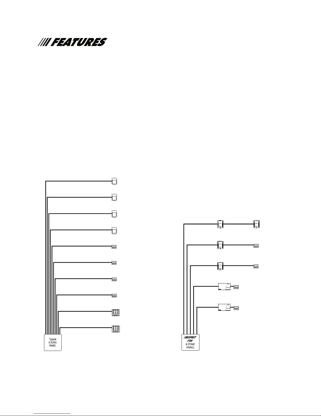
Advanced Technology Zoning (
728L, 728, 738,748
)
Advanced Technology Zoning software circuitry has been developed, which permits 2 zones and tamper
on a single pair of wires, as well as wire fault recognition. ATZ simplifies the task of meeting the zone
requirements of any application and, at the same time, reduces installation costs.
Zoning -
Traditional "Home Run" Zoning
the "Old-fashioned" Way
Zone 1
Detector
Zone 2
Detector
Zone 3
Detector
Zone 4
Detector
Zone 5
Door contact
Zone 6
Door contact
Zone 7
Door contact
Zone 8
Door contact
123
456
Keypad
789
ENTER
0
The Paradox innovation -
Advanced Technology Zoning
"Advanced Technology Zoning"
Zone 1 Zone 4
Detector
Zone 2
Detector
Zone 3
Detector
Keypad-1
Keypad-2
D
E
M
Zone 7
R
A
D
E
M
R
A
Zone 8
Detector
Zone 5
Door contact
Zone 6
Door contact
Door contact
Door contact
Note:
For tamper supervision,
install additional circuits.
123
6
45
Keypad
89
7
ENTER
0
Model 728 shown
Model 728 shown also
(also available on 728L, 738, 748)
available on 728L, 738, 748.
Note:
No additional circuits required
for tamper supervision
5
Page 8

FEATURES (continued)
Streamlined Keypad / PC Programming, User-friendly Operation
The reduced number of steps required to program Esprit panels via a keypad speeds up installation.
End-user access to most system functions calls for just one touch of the keypad.
IM8
Strategic System Partitioning (
728, 738,748,748ES
)
Each control panel can be used to monitor two distinct security systems, as well as common areas.
Partitioning provides a practical and flexible solution to situations where combined systems are a
neces
sity. User-friendly Esprit partitioning does it all with just one access code.
High-Speed Preprogrammed Communication
Esprit panels can slash set-up and reporting time by transmitting preprogrammed and high speed
communicator formats.
Event Buffer and “Real time clock” (
728L, 728, 738,748,748ES
)
Incorporation of a real time clock permits the creation of a 120 event, PC uploadable buffer with time and
date. Two automatic arming options are made possible by the inclusion of the "real time" clock. Auto
arming can be programmed to take place at specific intervals, or following a set time period without any
zone activity (auto arm and/or report only).
Programmable Outputs
Almost any control panel status situation may be used to activate the Esprit’s programmable outputs.
Once a panel status mode is selected for a PGM to follow, the polarity and duration of the output may
also be programmed. 18 supplementary programmable outputs are available with the SRI18 module,
which connects to the panel serial output.
Alarm Relay (
738, 748, 748ES
)
Single pole, double throw dry contacts rated at 5 amps that follow the local alarm (bell/siren) output.
Augmented Auxiliary Power (
748ES
)
1.2 amps of regulated auxiliary power supplied via 5 sets of power terminals. Ideal for applications with
numerous detection or ancillary devices. Requires a 75VA transformer.
Espload Upload/download Software
Espload upload/download software revolutionizes control panel supervision by delivering powerful panel
programming, modification, real-time monitoring and data management tools. It can function with most
Hayes-compatible modems, requires less than 60 seconds to transmit a full upload or download, and is
extremely simple to learn and to operate. The upload/download software is not permitted on UL installations.
Programming Guide and Simplified Bench Test
Want to get started right away? Please refer to the
"Programming Guide" for the specific Esprit control panel
that you are using.
6
Page 9

Digital Communicator:
Compatible with most telecommunication standards world wide.
Reporting formats:
Pulse: Ademco slow (10BPS), Silent Knight fast, Sescoa (20 BPS) Radionics, Radionics
with parity (40 BPS), 1400Hz - 1800Hz (20 BPS)
DTMF: Contact ID, Ademco Express, “No handshake” DTMF format.(Pager)
Optional SIA format (Standard on
708
)
True Dial tone detection and telephone line monitoring.
Full Up/down loadable with PC.
Regular, Split and Double reporting modes.
IM8
Event Buffer: (
728L, 728, 738,748,748ES
)
120 event buffer with time and date.
Operating modes:
17 User codes (2 Master codes) 4 or 6 digit codes. (
9 User codes (2 Master codes) 4 or 6 digit codes. (
Partitioning to System "A", System "B" and a Common area. (
728,738 748,748ES
718, 728L
)
728,738,748,748ES
)
)
Stay (at Home), regular, and auto bypass (Away) arming.
Fast “One key Full Arm”, “One key Stay Arm” and “One key Exit”.
Key Switch Arm/Disarm ("stay" or "regular" mode.)
PS1 bedside remote, 3 keypad-activated panic alarms.
Real Time Clock for "list of events", auto arming and test reports.
Auto arm on time or no zone activity delay time.
Inputs and Outputs:
Zones: N.C., EOL or "Advanced Technology Zoning" and wire/tamper recognition using 1 resistor per zone.
Battery Charger: 360mA with active Battery test.
Aux power: 400 mA, (UL, ULC installations) Fuseless electronic shut down at 1A, Automatic restore
Bell Out: 1A, (Fuseless electronic shut-down at 3A, Automatic restore)
AC input: 16.5 Vac, 40VA (75VA for
748ES
@ 1.2 amps)
PGM outputs: More than 1000 options to follow
2 operation modes: Timed (1 sec. to 2 hrs.) or following a predetermined condi
tion.
N.C. or N.O to ground, 30 mA Max. Can also be remote controlled by PC.
Serial Data Output (1200,1, N) for use with Accessory Modules
Accessory Modules:
SRI 18:
708DV:
18 PGM outputs,
708:
Secondary Digital Dialer (UL listed)
DVACS communicator (Canada only),
Esprint:
Parallel printer interface (not UL listed).
Keypads:
616, 626, 629 and 633 (LED) keypads. 639 and 640 (LCD) keypads, PS1 bedside remote. (For UL
systems use only 616, 626, 640 or PS1.)
Current consumption:
(measured with battery connected, without AC and 1KW resistor on bell and 1KW resistor on zones)
718
control panel
728
control panel
728L
control panel:29mA
738
control panel
748
control panel
748ES
control panel:60mA
:
29mA
:
29mA
:
25mA
:
37mA
PS1 bedside remote: 15mA DCTypical 639/640 LCD keypads: 20mA DCTypical
20mA DCMaximum 45mA DCMaximum
SR!-18: 50mA DCTypical
DC
DC
DC
DC
DC
DC
616/626 LED keypads: 15mA DCTypical
30mA DCMaximum
629 access control keypad: 30mA DCTypical
55mA DCMaximum
633 LED keypad: 15mA DCTypical
35mA DCMaximum
7
Page 10

LOCATION AND MOUNTING
The printed circuit board, mounting hardware and keypad should be removed from the packaging inside
the panel box. Press the five white nylon mounting studs into cabinet from the back prior to mount-
ing the cabinet. Before mounting the circuit board on the back of the cabinet, pull all cables into cabinet
and prepare them for connection.
Be sure to select a control panel installation site that is not easily accessible to intruders. Leave at least
2” around the panel box to permit adequate ventilation/heat dissipation. Installation location should be
dry, close to an AC source, ground connection and a telephone line connection.
EARTH GROUND
The earth terminal should be connected to the cabinet and grounding rod as per local electrical codes.
AC
Use a 16VAC transformer with a minimum 40VA rating to provide sufficient AC power (for
748ES
, use
75VA). Do not utilize any switch-controlled outlets to power the transformer. UL listed systems require
K12 model T16V40 transformer; ULC listed systems require Frost model FTC1637 transformer.
PROGRAMMABLE OUTPUTS
If the programmable outputs are to be used, they should ideally be connected through external relays, as
these outputs should not drive more than 30mA. A relay should be used in cases where more than 30mA
is required.
BELL/SIREN OUTPUT
Bells or other warning devices requiring a steady voltage output during alarms, are powered by the Bell+/
Bell- terminals. The bell output is microprocessor-controlled and will automatically shut down if current
exceeds 3 amps. The processor will allow current to resume only after the bell cut-off time expires.The
correct polarity connections should be made when hooking up sirens (speakers with built-in siren drivers). “Bell+” terminal is the connection for the positive lead. “Bell-” terminal is the connection for the negative lead. The bell output supplies 12V upon alarm. It can support two 20-watt or two 30-watt sirens.
(Above 1A, battery supplies current.)
AUXILIARY POWER TERMINALS
Motion detectors and any security devices requiring 12VDC voltage can be powered by the auxiliary
power supply. A maximum of 400mA 12VDC is available, (225mA for 748ES and 250mA max. for 24 hr.
standby-UL, ULC installations) from the AUX+ and AUX- terminals. For each additional keypad or PS1
module, the auxiliary current supply must be reduced by individual model current consumption. The auxiliary supply is microprocessor-protected against current overload and automatically shuts down if current
exceeds 1 amp. Auxiliary power will resume after battery test takes place, (within 0 - 60 seconds).
ZONE INPUT TERMINALS
(Please refer to zone connections (page 9) and wiring diagram in "Programming Guide".)
KEYPAD CONNECTIONS
The keypad has a terminal strip with 6 connections. The first 4 connections are labeled "yellow", "green",
"black" and "red". They are connected to the corresponding color terminals on the control panel board.
The last 2 connections are labeled " zone” and “COM". This is the zone input on the keypad. A green (1K
ohm) resistor must be used on this zone. If the zone input is not used, the green (1K ohm) resistor must
be installed on the terminal strip. The zone information is carried to the panel on the 4 wires of the keypad connection. Up to 5 keypads may be used on a system with 2 of the keypads utilizing the zone input.
Displayed as
718/728L/728 738/748/748ES
Keypad zone 1 Zone 7 (Partition B) Zone 13 (Partition A)
Keypad zone 2 Zone 8 (Partition B) Zone 19 (Partition B)
IM8
Jumper "off" - Keypad zone 1 activated.
Jumper "on" - Keypad zone 2 activated.
(Panel default jumper setting is "on" (keypad zone 2). To switch to keypad zone 1, a "keypad power
down" must be conducted. To do so, all 4 wires must be disconnected.)
8
Page 11

TELEPHONE LINE CONNECTION
Connect the incoming telephone company wires into "TIP" and "RING". Wires should then be run from "T1"
and "R1" to the installation's phone system.
POWERING UP THE UNIT
GENERAL
When keypads are installed far from the control panel, a keypad should be temporarily connected close
to the panel to conduct "power-up" testing. Connect the transformer. After 5 seconds, begin testing the
unit. Enter random commands on the keypad. It should "beep" in response to these commands. Open a
zone to ensure that keypad and panel are responding to signals. If the keypad does not respond and if no
indicator lights illuminate, check for AC voltage at the “AC” terminals. If 16VAC is flowing, then keypad
wiring should be verified. Also check for a short between "black" and "red' keypad wires.
PANEL PROGRAMMING METHODS
To conduct panel programming, use the keypad or initiate communication with Espload (see page 21).
Use of
programming. For Keypad Programming, see "Programming Guide".
BATTERY HOOK-UP (required on UL/ULC installation)
Warning: Do not connect transformer or battery until all wiring is completed. Use a 12VDC 7AH
rechargeable acid/lead or gel cell battery. Connect "red" battery lead to positive battery terminal, and
"black" battery lead to negative battery terminal. Reversed connections will blow the battery fuse. Battery
should not be connected until AC panel connections have been made. After connecting battery [TRBL]
key should illuminate. Pressing [TRBL] causes key [8] to illuminate (trouble indicator for "timer loss"). (See
"Trouble Display Monitoring" section, p. 18-19)
Espload
is highly recommended, as it greatly reduces the potential for data entry errors during
IM8
BATTERY TEST
The panel verifies battery connection every 60 seconds. If the battery is not connected, trouble indicator
key [1] illuminates. If battery is connected, a 4 second test of battery under load is conducted. Every
hour, a 64 second battery test will be carried out (not applicable to software versions 1.4 and beyond).
Panel arming can be blocked if the battery test fails, if programmed. Test failure causes trouble indicator
key [1] to illuminate, indicating that battery capacity is insufficient. When the panel runs on battery power,
with or without AC, if battery voltage drops to 10.5 volts, trouble indicator key [1] will illuminate. (If programmed, a trouble report code will also be sent to the central station.) At 8.5 volts all outputs are closed.
ZONE WIRING CONFIGURATIONS AND OPTIONS
The selection of the panel (number of zones) should be based on the requirements of a security installation.
LOOP CONFIGURATIONS AND ZONE CONNECTIONS
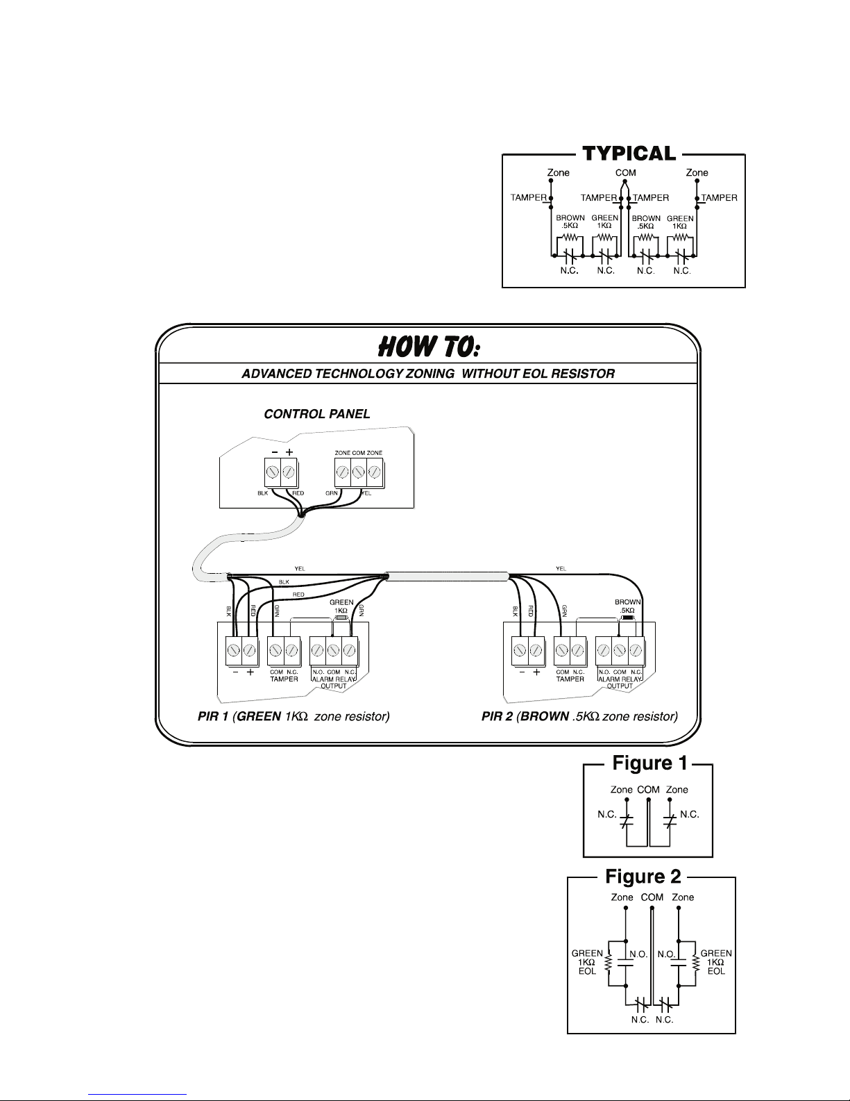
Single zones can be configured for N.C. contacts without EOL, or zone resistors (see Fig. 1, page 10). By
using 1 zone resistor, single zones can be configured for N.C. and/or N.O. contacts (see Fig. 2, page 10).
A single zone can also be configured to detect alarm and tamper (tamper will transmit a separate distinct
signal and cause the zone light at the keypad to flash) see Fig. 3, page 11.
Note: Configuring zones in single zone mode reduces number of available zones. (728L, 728, 738,
By utilizing 2 zone resistors (see "Typical", pg. 10) each loop (pair of wires) will recognize two distinct alarm
zones for N.C. contacts. A separate "tamper" signal can also be transmitted and displayed on the keypad
(flashing zone light). Adding a green (1K OHM) EOL resistor will provide loop supervision (see Fig. 4, pg. 11).
Notes:
1) Two zones per loop configuration reduces wiring and installation requirements by permitting the
connection of two distinct zones per input (loop), on the same pair of wires. Coverage is not compromised in any way. Each zone can be reported separately, based on different resistor values, and the
same pair of wires can also provide "anti-tamper" and "wiring failure" recognition. In order to have
Advanced Technology Zones, enable at address 210, key [8].
748)
2) The input terminals are marked with 2 digits ex. 1/4, 1/13. These digits indicate the two zones that
are associated with that input when ATZ (zone doubling) is used. Two resistors are required when ATZ is
operational.The first digit (regular zone) is identified by a green (1K ohm) resistor, and the 2nd digit (doubled zone) is identified by a brown (.5K ohm) resistor.
9
Page 12
The system hardware will recognize the following conditions for each zone:
ADVANCED TECHNOLOGY ZONE connection, 2 zone resistors (without EOL), tamper
*
recognition (N.C. contacts)
address 208, key [MEM] = "on"
key [10] =
key [11] =
address 210, key [8] = "on"
Tamper fault transmits separate code.
Each zone transmits separate alarm code, see "TYPICAL"
4 Alarm zones
2 Tamper signals
See "Tamper/wire Fault Definitions
and Options"
IM8
*Not available on models
718, 748ES
SINGLE ZONE connection without EOL resistor (N.C. contacts)
address 208, key [MEM] = "on"
key [10] = "off" (default)
key [11] = "off" (default)
address 210, key [8] = "off”
N.C. contacts see Figure 1
Note: Keypad zones always use a green (1K OHM) EOL resistor.
SINGLE ZONE connection with 1 EOL resistor
(N.C. and N.O. contacts)
address 208, key [MEM] = "off" (default)
key [10] = "off" (default)
key [11] = "off"(default)
address 210, key [8] = "off"
N.C. and/or N.O. contacts, see Figure 2
10
(UL/ULC configuration)
Page 13

IM8
SINGLE ZONE connection with 1 green (1K
OHM
) EOL resistor, tamper recognition (N.C. contacts)
address 208, key [MEM] = "off"
key [10] =
key [11] =
See "Tamper/wire Fault Definitions
and Options"
address 210, key [8] = "off"
Tamper fault transmits separate code, see Figure 3
(UL/ULC configuration)
*
ADVANCED TECHNOLOGY ZONE connection, 2 zone with zone resistors, 1 green (1K
resistor tamper (open) recognition, wire fault (short circuit) recognition (N.C. contacts)
address 208, key [MEM] = "off"
key [10] =
key [11] =
See "Tamper/wire Fault Definitions
and Options"
address 210, key [8] = "on"
Tamper fault transmits separate code. Each zone transmits
separate alarm code. Wire faults (short circuit) transmit alarm
codes, and are indicated by fast flashing zone light on keypad
and reported in
*Not available on models
Espload
, see figure 4.
718, 748ES
(UL/ULC configuration)
OHM
) EOL
11
Page 14

Tamper/wire Fault Definitions and Options
When using 2 zone resistors, the panel offers four possible definitions for line/tamper wiring recognition,
independent of zone definition.
"Tamper/wire” disabled (Address 208, Key [10] "off", Key [11] "off")
Tamper/wiring failure recognition is disabled. (Also disables ATZ zone doubling for software versions
prior to 0.98.)
"Trouble" enabled (Address 208, Key [10] "off", Key [11] "on")
Tamper/wiring failure will generate an alarm, when armed. A trouble report code will be sent to the
central when disarmed. (Also enables ATZ zone doubling for software versions prior to 0.98.)
"Silent alarm" enabled (Address 208, Key [10] "on", Key [11] "off")
Tamper/wiring failure will generate a silent alarm (no siren) when the system is disarmed. Alarm
and trouble report codes will be sent to the central. (Also enables ATZ zone doubling for software
versions prior to 0.98.)
"Audible alarm" enabled (Address 208, Key [10] "on", Key [11] "on")
Tamper/wiring failure will generate an audible alarm (siren). Alarm and trouble report codes will be
sent to the central. (Also enables ATZ zone doubling for software versions prior to 0.98.)
IM8
Exception:When the zone definition is "24 hour", the tamper definition follows the audible/silent
alarm arm definition of the "24 hour" zone.
Tamper recognition addresses:
Tamper report and restoration codes should be programmed at addresses 191 and 180.
Fire circuit
The fire zone (enabled by defining zone 3 (zone 12 for software versions prior to 0.98) as "24 hour') should
always be connected with a 1K OHM EOL resistor (UL-PN201100200-PRT). If there is a line short in the fire
zone, a fire alarm will be generated. If the line is
"open", a "fire loop" trouble report will be sent to the cen-
tral and trouble indicator [11] will illuminate on the keypad.
For UL/ULC installations, a 4 wire, latching, smoke detector (UL- Falcon Model 5454, ULC - BRK Model
2412) must be used along with a
1K OHM EOL resistor
. To supervise the power, an “end of line” relay
(Model MR3) should be installed, the contacts of which will cause a FIRE TROUBLE in the event the
power is interrupted.
To reset (unlatch) the smoke detectors after an alarm, power to the detectors must be momentarily interrupted. One way to accomplish this is to connect the negative (-) side of the smoke detector power to
PGM 1. Then program the PGM to be N.C. (normally closed), and to “open” when the [TRBL] and [11]
keys are pushed in sequence.
Example: To program PGM1 for smoke detector reset:
Address 195 = [BYP]
Address 196 = [5] [3]
Address 198 = [2] [2ND]
Address 254 = [10] [10] [4]
12
Page 15

GUIDELINES FOR SMOKE DETECTOR LOCATION
Smoke Detection.
Where to locate Smoke Detectors in Existing Construction.
The major threat from fire in a family living unit is at night when everyone is asleep. The principal threat to
persons in sleeping areas comes from fires in the remainder of the unit; therefore, smoke detector(s) are
best located between the bedroom areas and the rest of the unit. In units with only one bedroom area on
one floor, the smoke detector should be located as shown in Figure 1. In family living units with more
than one bedroom area or with bedrooms on more than one floor, more than one smoke detector will be
needed, as shown in Figure 2 and 3.
Smoke Detector Mounting - Dead Air Space.
The smoke from a fire generally rises to the ceiling, spreads out across the ceiling surface, and begins to
bank down from the ceiling. The corner where the ceiling and wall meet is an air space into which the
smoke may have difficulty penetrating. In most fires, this dead air space measures about 4 in. (0.1m)
along the ceiling from the corner and about 4 in. (0.1m) down the wall as shown in Figure 4. Detectors
should not be placed in this dead air space.
IM8
Figure 1. A smoke detector should be located
between the sleeping area and the rest of the
family living unit.
Figure 2. In family living units with more than
one sleeping area, a smoke detector should
be provided to protect each sleeping area in
addition to detectors required in bedrooms.
Figure 3. A smoke detector should be located
on each storey.
Figure 4. A smoke detector should be located
on each storey.
13
Page 16

INTRODUCTION
The
Esprit
's innovative keypads take a new approach to security features and functions. Each numeral
on the keypad from 1 to 12 represents an actual zone. When the [2ND] key flashes, (depending on the
model number of the control) the same numerals represent a second set of 12 zones, zones 13 to 24.
(The [2ND] key will first light up to indicate that one or more of these zones (13-24) are open. Pressing on
the [2ND] key will then cause it to flash.) When the zone light is "off", the status in the protected zone is
normal. If the zone light is "on", this means the zone is open.
"CONF" confirmation beep: an intermittent series of beeps that indicates that the keypad entry was successful.
"END/REJ" end/rejection beep: 1 long tone indicates that the operation was incorrectly entered on the keypad.
SYSTEM ARMING/DISARMING OPTIONS
Regular System Arming (default code 474747)
(Without partitioning - for information on partitioned system arming, see pages 15, 16)
The green "ready" light must be illuminated. This "ready" indicator will only illuminate if all zones are
closed. All door/window contacts must be closed, and any movement in motion detector-protected areas
must be halted. When the "ready" light illuminates, a valid access code should be entered.
Upon entry of this code, the red "armed" light will illuminate, followed by the keypad "CONF" beep. (If the
access code is entered incorrectly, the "END/REJ" beep will sound. If an incorrect entry is made at any time,
press [CLEAR] and re-enter the data.) The green "ready" light will flash for the period of the exit delay, and
the [STAY] and [AWAY] keys will flash.
Note: Keypad will beep on exit if programmed at address 208 key [12].
IM8
Auto bypass (away) arming (key [AWAY])
To arm the system rapidly without manually entering zones to be bypassed (and/or to leave the protected
area without waiting for the "ready" light), use the "AWAY" auto bypass feature. The [AWAY] key should be
pressed, followed by a valid access code (address 202). (The "ready" light does not have to be "on", but
all open zones must be "bypass-enabled" (addresses 236 and 238). Once the exit delay expires, any
open zones will automatically be bypassed and the system will be armed. Armed status is indicated by
illumination of the [AWAY] key. (The fire zone cannot be bypassed.) If any zones have been left open, the
[BYP] key will illuminate to indicate that zones have automatically been bypassed. A partial arm code will
be sent if programmed.
Please note: This feature is not recommended for regular use because bypassing zones can reduce the
efficiency of system protection. Zones remain bypassed until disarming.
Auto away arming
If an access code used to arm the system has been assigned "away" (address 202) priority, and an open
zone is bypass enabled (addresses 236 and 238), activation of "auto away" arming at address 210, key
[3], will permit "away" arming to take place without pressing the [AWAY] key. The feature must not be
enabled on UL listed systems.
Stay Arming [STAY] + access code
When "stay arming" is activated, the security installation is "partially" armed. This means that selected
STAY zones are armed (address 240, 242), so that users (address 200) can remain in the protected area.
This convenient feature offers individuals arming the system the choice to leave the premises during an
exit delay (without altering the "stay arm" status), or remain on the premises. A system user returning to a
protected area that is "stay" armed ([STAY] key is "on") can re-enter and disarm, as long as a valid access
code is keyed in during the entry delay.
Fast "regular" arming Key [10]
Fast arming is enabled at address 208 (key [7] "on"). If activated, when the ready light is on, pressing key
[10] for 2 seconds automatically arms the system. There's no need to enter an access code. This feature
can be used to permit selected individuals (i.e. maintenance workers, repair personnel) to full arm the system when leaving the protected area. (When partitioning is enabled, key [10] arms system "A" and "B".)
14
Page 17

Fast "stay" arming key [11]
Fast "stay" arming is enabled at address 208 (
key [8]
"on"). When activated, no "ready" light is required,
however "stay" zones must be closed to arm the system. Pressing [STAY] (key [11]) for 2 seconds automatically "stay" arms the system. (See "stay" arming features.)
Double "stay" arming (software versions 0.98 and beyond)
During the exit delay, pressing [STAY] (key [11]) again will switch any delay 1 or delay 2 zones to instant
zones. (24 hour "stay" zones, follow "stay" zones, and instant "stay" zones are not affected.) Regular and
partitioned systems provide this feature; however, in a partitioned system the only zones affected will be
"System A" zones. Full system arming cancels "double stay" arming.
Fast exit
Exit while the system is armed in "stay" mode (key [11/STAY] is flashing):
A: Fast exit and Stay key [11]
To exit the premises and remain "stay armed": press key [11/STAY] for two seconds. The system switches
to "exit delay" mode ("ready" LED flashes). At the end of the "exit delay" period, the system will return to
"stay" arming mode.
B: Fast exit and Regular Arm key [10]
To exit the premises and "regular" arm: press key [10] for two seconds. The system switches to "regular"
arming (key [11] and [12] are flashing) with "exit delay" ("ready" LED flashes). At the end of the "exit
delay" period, the system is "regular" armed.
IM8
System disarming
The protected area should be entered through a designated entry/exit door. The keypad sounder will
beep to remind user to disarm the system. A valid access code should be entered on the keypad, before
the allotted entry time expires. If the access code is entered incorrectly, press [CLEAR] and re-enter it. The
"armed" light will extinguish and the sounder will change to the "CONF" beep (series of short beeps)
before silencing.
Alarm memory
When disarming the system (or resetting the alarm), the memory light [MEM] will illuminate if any alarm
situations took place during the preceding armed period. A record of all alarm situations that occurred
while the system was armed is stored in memory. After disarming the system, pressing once on the [MEM]
key causes it to flash and brings up the alarm events, which are displayed on the keypad. (Alarm events
consist of all zones that generated alarms.)
SYSTEM PARTITIONING
GENERAL
By activating the panel's "partitioning" feature, zones can be divided into two distinct systems, with a
shared fire zone (zone #3). Both systems are controlled by one panel, making partitioning a particularly
useful feature in installations where shared security systems are more practical (i.e. office/warehouse,
apartment/condo complexes). The 718, 728L, 728, 738, 748 are not UL listed for commercial application.
PARTITIONING (
Partition "on" (Address 206, key [8] "on")
Addresses 240 and 242:
Regardless of the control panel model, Partition “A” (account code A) will always consist of zones 1 to 6
and zones 13 to 18. Partition “B” will always consist of zones 7 to 12 and 19 to 24. A “Common Zone” is a
zone common to (connected to) both partition “A” and “B”. If Partition “A” or “B” is disarmed, common
zones will be disarmed. Both Partition “A” and “B” must be armed for “Common Zones” to be armed.
728, 738,748,748ES
)
All zones are “Common Zones” unless they have been designated as “A” only or “B” only (not common)
at address 240 and 242.
15
Page 18

Panel "A" Partition Zones "B" Partition Zones Total Possible Zones
748, 748ES
738
728
1-6, 13-18, 13 = (Keypad 1) 7-12, 19-24, 19 = (Keypad 2) 24
1-6, 13(Keypad 1) 7-12, 19 (Keypad 2) 14
1-6 (See note) 7 (Keypad 1), 8 (Keypad 2) 8
IM8
Notes re:
728
(also see page 27)
The designation for zones 1, 2, 3,4,5 and 6 can be changed to zones 7, 8, 9,10,11 and 12
respectively so that they form part of partition “B”.
Zones 1 and 2 will be swapped with zones 7 and 8.
Note: When partitioning is not activated (address 206, key [8] "off") any zones selected at addresses
240 and 242 will be armed upon "stay" arming.
Keypad display:
Both systems are displayed on the keypad at the same time. In partitioning mode, when System "A" is
armed, the [STAY] key flashes. If System "B" is armed, the [AWAY] key flashes. If both systems are armed,
both of these keys will flash.
ARMING/DISARMING
Code definition:
Partition "on" (Address 206, key [8] "on")
Address 200: Designates access codes that arm System "A" zones.
Address 202: Designates access codes that arm System "B" zones.
Address 204: Designates access codes that can "bypass" zones
When a code is activated at both addresses (200 and 202), it can do the following:
1) The code can fully arm the system. If the code is entered when systems "A" and "B" are
disarmed, it will completely arm the system.
2) The code can fully disarm the system. If the code is entered when system "A" and "B" zones
are armed, it will completely disarm the system.
3) When the system is partially armed (i.e. only System "A" or "B" is armed) entering this code will
arm the other system.
4) The code can be used to selectively arm/disarm System "A" or System "B" zones.
Enter [11] + code to arm/disarm System "A" zones.
Enter [12] + code to arm/disarm System "B" zones.
Note: Codes that are not selected at either address are disabled.
The master code can always access both systems and bypass zones.
(1) System "A" codes can stop sirens coming from System "B" zones (and vice versa), but will not
disarm the other system.
(2) It is not possible to arm one system during the other system's exit delay.
Note: When partitioning is not activated, (address 206, key [8] "off"):
Address 200 determines which access codes can activate "stay" arming.
Address 202 determines which access codes can activate "away" arming.
Address 204 determines which access codes can "bypass" zones.
16
Page 19

KEYSWITCH/PUSH-BUTTON ARMING/DISARMING (PS1)
In parallel to keypads, a keyswitch or push button can be used to arm/disarm the system. (The
PS1 can be installed in bedrooms or any other desired location.) Keyswitch/push button operation is
enabled/disabled at address 206, key [3] "on". Keyswitch can activate "regular" or "stay" arming, based
on the definition assigned at address 206, key [2]. (key [2] "off" = "regular" arming, key [2] "on" = "stay"
arming) If "stay" arming is activated, the keyswitch/push button (PS1) cannot be used to disarm the system if it is in entry delay or if an alarm has been generated. In this case, the system can only be disarmed
from a keypad. (When partitioning is activated, the keyswitch can be used to arm/disarm System "A"
regardless of System "B" status. Pressing key [11] will arm System "A".) Pressing two keys on the PS1
simultaneously for 2 seconds will generate a "panic (1)" alarm (see "Keypad (Panic) Alarms).
Esprit
ZONE BYPASSING
MANUAL
Bypassed zones will not generate an alarm. Manual bypass arming is employed when a system user
chooses not to arm the entire protected area. Only zones that have been defined as "bypass enabled"
(addresses 236 and 238) can be selected by the user (address 204) during manual bypass arming. To
bypass zones, enter [BYP] + a valid access code. [BYP] key will illuminate. When a zone light is on, it indicates that the zone has been bypassed. Pressing [CLEAR] erases all bypass entries and current bypass
zones and will exit the bypass mode. Zones to be bypassed should then be re-entered. If bypass information is correct, press [ENTER] to end and save bypass functions being programmed. [BYP] key will
remain illuminated, indicating that some zones have been bypassed. To cancel the zone bypass "status"
just entered, press [BYP] + user code + [CLEAR]. Zone bypasses are automatically cancelled every time
the system is disarmed, except in "24 hour" zones. If a "24 hour" zone is bypassed and the system is
subsequently disarmed, the "24 hour" zone will remain bypassed.
Note: When partitioning is used, zones assigned to the other system cannot be bypassed if that system
is armed.
IM8
BYPASS RECALL
This feature permits system users to reinstate the latest zone bypass instructions saved in memory. By
pressing [BYP] while in bypass programming mode, previous bypass status is re-established. Even if a
user is in process of entering new bypass information on keypad, one touch of the [BYP] key overrides
new information and reinstates the preceding zone bypass instructions saved.
Reminder: The fire zone cannot be bypassed.
CHIME ZONES
Chime zones report a presence (movement or door opening) in the selected zones by emitting a distinctive rapid intermittent beep. Each keypad is independently "chime" programmed and must be reprogrammed in the event of total power loss. To enable a zone's chime feature, press the selected zone key
[1] to [6] until the rapid intermittent beep is heard. To enable the chime feature of the keypad zone connected to the particular keypad, use key [8]. To disable a zone's chime feature, press on the appropriate
key until a steady beep is heard. Disable keypad souder (mute), (heading), press key [9].
KEYPAD (PANIC) ALARMS
The Esprit provides three “Panic” zones on the keypad. Keys must be pressed simultaneously for 2 seconds in order to activate. (Pressing 2 keys on the PS1 for 2 seconds generates a "panic 1" alarm.)
Alarm Press Alarm Code Silent/Audible Silent/Fire
keys Address Address Address
Panic 1 [1] & [3] 184 (SECTION 31) 208, Key [4]
Panic 2 [4] & [6] 185 (SECTION 31) 208, Key [5]
Panic 3 [7] & [9] 186 (SECTION 31) 208, Key [6]
17
Page 20

TROUBLE DISPLAY/MONITORING
Trouble status is continuously monitored by the panel. It can recognize and display 10 different trouble
conditions on the keypad or in
reports" to the central, 2-digit trouble report codes should be programmed.)
When trouble conditions occur, the [TRBL] key illuminates and if "trouble warning" is enabled (address
210, key [9]) the keypad will beep intermittently. Press [TRBL] to switch keypad to "trouble display" mode.
[TRBL] key flashes. Keys that are "on" indicate current trouble conditions and those in memory. Press any
key except [2ND] to return keypad to normal display. Press [2ND] to view current troubles only. Press
[CLEAR] to erase previous trouble conditions in memory, and to silence trouble warning.
Espload
, and report 8 to the central station. (To send "trouble status
IM8
Key [1]
Battery is disconnected from the panel, or capacity is low. Panel conducts dynamic battery test under
load every minute for a 4 sec. period, and every hour for a 64 sec. period. Key [1] "on" indicates battery
is disconnected, or it should be replaced because it won't provide adequate back-up current in event of
AC loss. Trouble indicator [1] also comes "on" if battery voltage drops to 10.5 volts while panel is running
on battery power (with no AC).
Note: System can be programmed to inhibit arming if no/low battery condition exists - Address 210, key [4].
No battery/low battery
Key [2] Power failure (software versions 1.4 and beyond only)
Inadequate AC power is going to panel and/or power supply is unable to charge battery and/or power
supply voltage exceeds 14.9V. (Report can also be sent to central, and “power failure” report delay time
is programmable at address 252. Delay duration can be from 000 - 255 minutes; default = 30 min.) To
remove “power failure” from trouble display, [2ND] key should be “on” at address 210.
Key [3]
Inadequate AC power is going to panel. (Report can also be sent to central, and "AC failure" report delay
time is programmable at address 252. Delay's duration can be from 000-255 minutes, default = 30 min.)
To remove "AC failure" from trouble display, at address 210, [2ND] key should be "on".
Key [4]
Bell is not connected to bell output. Note: When connecting bell to optional relay output, trouble indicator
[4] is "on" constantly. To avoid this, connect a green (1KW) EOL resistor on bell output. If an internal
siren is connected to bell output, and an external siren to relay, the panel will only recognize the existence of the internal siren.
Key [5]
Processor has recognized that, upon alarm, bell output current exceeds 3A., causing automatic shutdown of bell output. After opening the short or reducing the load, bell shut-down will end upon bell cut-off.
AC power failure (software versions prior to 1.4)
Bell disconnect
Maximum bell current
Key [6]
Processor has recognized that auxiliary output current exceeds 1A. (748ES-3A) This causes automatic
shut-down of auxiliary output. After opening the short or reducing the load, power will be automatically
restored to the auxiliary output after battery test has been conducted (within 60 seconds).
Key [7]
The control panel has unsuccessfully attempted to initiate communication with the central. Report failure
is stored in "event list" memory.
Key [8]
After total battery/AC power failure, the timer must be reprogrammed. To do so, press [ENTER] + code +
[MEM], followed by correct time (00 - 23 for hours, 00 - 59 for minutes) + [ENTER] + [ENTER] + [TRBL] +
[CLEAR].
Key [9]
A zone line cut/line short has occurred. Tamper/wiring recognition must be activated at address 208 if
this feature is required. EOL resistors must also be used for zone connection.
Maximum auxiliary current
Communicator report failure
Timer loss
Tamper/zone wiring failure
18
Page 21

IM8
Key [10]
Telephone line monitor
Telephone line cannot be found for 30 seconds. "Telephone line monitor" is enabled at address 206. This
trouble condition can also trigger an alarm when the system is armed, if activated at address 206. It will
also be stored in "event list". Restoration of telephone line can be reported by programming address 183.
Key [11]
Fire trouble
The zone wire has been cut on *zone 3 (when its zone definition is "24 hour fire"). Fire zone *key [3] also
flashes. If programmed at address 174, it will be reported to the central.
*Zone 12 and key [12] for software prior to 0.98.
END-USER PROGRAMMING
MASTER AND USER CODES
[ENTER] + master code + code number (2 digits)+ new code (4 or 6 digits, 0 to 9) + [ENTER].
Use [2ND] to erase a code.
Master code = 00 ([10][10]) Full access to all system functions.
User codes = 01-16 (728, 738, 748, 748ES) and 01-08 (718, 728L)
(01 - can modify access codes. All user code priorities can be programmed
at addresses 200, 202, 204, using the installer code.)
Note: [2ND] key flashes if location is empty (no code programmed).
"ONE-KEY" USER PROGRAMMING COMMANDS
Several panel features can be programmed quickly, without entering addresses or section numbers. Select
"one-key access" programming mode by pressing [ENTER], followed by INSTALLER, MASTER OR USER
CODE (depending on feature you wish to activate, only certain codes will be functional). Then press the single key (listed below) corresponding to the feature you wish to enable.
KEY
[9] Program "auto arming" time:
Enter two digits (00 to 23) for hours + 2 digits (00 to 59) for minutes + [ENTER].
To disable program, [2ND], [2ND].
[MEM] Program "panel time"
Enter two digits (00 to 23) for hours + 2 digits (00 to 59) for minutes + [ENTER]
[BYP] Test report
Reporting is enabled at address 206, key [11], [12]. A value must be entered at address 175,
and both telephone and account numbers should be programmed.
[TRBL] Call Espload via telephone
Panel and PC ID numbers (addresses 001-004) and PC download phone number
(addresses 060-067) must be programmed.
[AWAY] Answer Espload
This feature is available when using the ADP-1 adapter. In
be activated in "modem setup" section and panel phone number programmed
[STAY] Cancel communication attempts
Until next reportable event.
[STAY] Reset to default panel settings
Connect reset jumper on circuit board (see wiring diagram).
Press [ENTER] + installer code + [STAY], remove reset jumper.
[2],[6] Installer test mode
In installer test mode, a confirmation beep (intermittent) indicates test is "on", a "rejection" beep
(long) indicates test is "off". The bell will squawk during walk testing to indicate open zones.
[2],[7] Streamlined value entry
(see Installer programming page 21.)
(default master 474747)
(accessible to Master and User 1 only)
(all 3 codes)
(all 3 codes)
(all 3 codes)
(all 3 codes)
(master code and user 1 can only stop calls from/to Espload.)
(installer code - all communication)
(installer code only)
(installer code only)
(installer code only)
Espload
, "blind dial" must
.
Note: When communicating with Espload, programming mode cannot be accessed.
19
Page 22

"NO MOVEMENT"
If a time is programmed at address 253, and a report code is entered at address 190 (SECTION 32), the
panel will send a report to the central if no movement takes place in the protected area for a designated
time period.
"LATE TO CLOSE"
If the system is not armed by a specified time (addresses 245, 246) the code programmed at address
190 (SECTION 32) will be transmitted.
AUTO ARMING
The panel can be programmed to automatically arm itself every day in two ways: at the same time programmed for the auto test report (addresses 245, 246) and/or once the "no movement" delay has
elapsed (address 253). To program "auto arming", go to address 206 and enable key [5] (auto arm on
time), and/or key [6] (auto arm on "no movement"). All zones must be closed in order for system to auto
arm. If panel fails to auto arm the "no movement/late to close" report will be transmitted.
Note: The "auto arm" report is programmed at address 188, SECTION 32.
IM8
OPERATIONAL NOTE REGARDING SPECIAL TIMING FUNCTIONS
The time programmed at addresses 245, 246 can be used to:
1 Auto-arm the system and if programmed, transmit the arming code at address 188 (SECTION 32)
2. Specify the time of day for the Test Report, the code programmed at address 175 (SECTION 28)
3. Transmit the Late to Close/No Movement code, address 190 (SECTION 32), if the system is not
armed.
The amount of time programmed at address 253 (Max = 63.75 hours) can be used to;
1. Transmit the Late to Close/No Movement code, address 190 (SECTION 32), if there is no movement in the protected area while the system is disarmed.
2. Auto-arm the system and if programmed, transmit the arming code at address 188 (SECTION 32)
after transmitting the Late to Close/No Movement code (as above).
The "late to close/no movement" code programmed at address 190 (SECTION 32) will be transmitted;
1. at the time programmed at addresses 245, 246 if the system is not armed (Late to Close).
2. after the time programmed at address 253 expires (No Movement).
The amount of time programmed at address 254 (Max = 127 minutes) can be used to:
1. keep a programmable output (PGM) active for up to 127 minutes after a certain event.
20
Page 23

ESPLOAD
Esprit control panels can be programmed remotely with Espload upload/download software or on site with
Espload and a ADP-1 adapter. Contact your local Paradox Distributor for your free copy of Espload software.
KEYPAD
To program Esprit panels via the keypad, first complete the programming work sheets and follow the programming procedure. Both are found in the "Programming Guide".
(Used to program "Access to Upload/Download" and "Installer Code") All digits from 0 to F are valid.
Programming values are programmed into memory locations from address 000 to 007.
ENTER
1)Press [
2)Key [
ENTER
3)Enter 3 digit memory address (000-007)
4)Enter 2 digit data
5)To erase, press [
6)Go to step 3 for next address.
To exit programming mode press [
] + installer code (default 747474)
] will flash (programming mode)
CLEAR
]. To save press [
CLEAR
ENTER
]
]
IM8
PROGRAMMABLE FEATURES
(Features are presented in same order as in the programming worksheets in "Programming Guide".)
ACCESS TO UPLOAD/DOWNLOAD
PANEL ANSWER: (Address 000) DIRECT ADDRESS
(software versions prior to 1.4)
This value entry determines the number of rings required before the panel will answer. If [2ND][2ND] is
entered, the panel will not answer. The panel default setting is 08 rings.
Related features: "Callback"
206, [4]
"Answering machine override"
206, [BYP]
(software versions 1.4 and beyond)
The first digit entered at address 000 disables the “Answering Machine Override” (key [2ND] or key [1]),
or determines the period of time between first and second call when override is enabled.
The second digit entered at address 000 determines the number of rings required before the panel will
answer. If [2ND][2ND] is entered, the panel will not answer. (Default value is [2ND] [8].)
Value entered disables this feature or determines the period of time between first
and second call when enabled.
[2ND] or [1] - Answering machine override disabled
[2] = 16 seconds [3] = 24 seconds [4] = 32 seconds
[5] = 40 seconds [6] = 48 seconds [7] = 56 seconds
[8] to [F] = 60 seconds
UPLOAD PANEL IDENTIFIER: (Addresses 001, 002) DIRECT ADDRESS
This four digit code identifies the control panel to the PC before uploading can be initiated. Each pair of
code digits has its own memory address. There is no default code. Any hexa digits from 00 - FF can be
entered. Program first 2 digits in address 001 and second 2 digits in 002.
Related features: "Panel Answer"
000
"Callback"
206, [4]
"Answering machine override"
206, [BYP]
PC DOWNLOAD PASSWORD: (Addresses 003, 004) DIRECT ADDRESS
This four digit download password identifies the PC to the panel prior to beginning the programming
download process. Program first 2 digits in address 003 and second 2 digits in 004.
21
Page 24

INSTALLER CODE: (Addresses 005, 006, 007) DIRECT ADDRESS
The default installer code contains 6 digits - 747474. (Codes can also be programmed to contain 4 digits,
address 208, [9] "on".) Create a new installer code by entering values of 1st and 2nd digit at address
005, 3rd and 4th digit at address 006, and 5th and 6th digit at address 007. The installer code has access
to all programming addresses, except 008-058. It does not provide access to arming/disarming or user
code programming. It can be used to modify itself. (Use only numeric keys from [1] to [10] (key [10] = 0)
to enter installer code.)
Related features: "Installer lock"
(Used to program sections 00 to 34)
To begin programming
ENTER
Press [
Enter 2 digit section for programming (00 - 34) ([
Enter 8 digits to program the section. Keypad will beep verifying completion of section programming.
Data is saved and the next section is advanced to automatically for programming.
To select a specific section press [
Enter 2 digit section (00-34) ([
To exit programming mode press [
] + installer code + [2] [7] ([
255, "
panel reset" "access code length"
ENTER
] and [2ND] keys will flash)
ENTER
] key is "steady" and [2ND] key is "off")
CLEAR
] or [
ENTER
] ([
ENTER
] and [2ND] keys will flash).
ENTER
] key is "steady" and [2ND] key is "off").
CLEAR
].
208, [9]
IM8
TELEPHONE AND ACCOUNT NUMBERS STREAMLINED OR DIRECT ADDRESS SECTIONS 00 - 06
Three telephone numbers can be programmed: a PC telephone number, and two central station numbers.
Each number can contain a maximum of 16 digits.
Special instructions can be entered in the telephone numbers using the following keys:
[10] = the number "0"
[11] =
[12] = #
*
[BYP] = switch from pulse to tone while dialing
[MEM] = pause 4 seconds
[TRBL] = end of number
If only one central station telephone number is available, the same telephone number must be programmed for telephone number 1 and 2. A separate "communicator reporting" format can be selected for
each central station telephone number at address 194.
PC Download Telephone Number: (Addresses 060-067) SECTION 00 - 01
The PC download telephone number is dialed in three situations. It is dialed when communication with
PC is initiated from the keypad. It is the automatic "callback" number, when the "callback" feature is
enabled (206, [4] "on"). If the event buffer is full, and "call PC" feature is enabled (208, [2ND] "on"), this
number will be dialed in order to download the event list.
Related features: "Upload Panel ID"
001 - 002 "
PC password"
003 - 004
Central Station Telephone Number 1 (Addresses 068-075) SECTION 02 - 03
Central Station Telephone Number 2 (Addresses 076-083) SECTION 04 - 05
The panel can communicate with two central station numbers. Each of the numbers can be assigned a
separate reporting format. (Format selection - address 194, all keys).
Espload note: Upon alarm, upload/download in progress will be interrupted and the panel will dial the central.
If another type of reportable event occurs, Espload provides the on-screen prompt: "Hang up or continue?"
System Account Codes (System "A"/"B") (Addresses 084-087) SECTION 06
All report codes are preceded by a system account code to ensure correct identification of active zone(s)
in a partitioned system. If partitioning is deactivated, or you are using Esprit 718 or 728L, the same
value should be programmed for both account numbers. To program account codes for System "A"
and "B", press [ENTER] + installer code + [2][7] + [10][6]. The first four digits entered afterwards correspond to the System "A" account code, and the last four digits to the System "B" account code.
22
Page 25

REPORTING CODES: (Addresses 088-193) SECTION 07- 33
General
DIRECT ADDRESS OR STREAMLINED PROGRAMMING
The panel can report information regarding system and "protected area" status to the central monitoring
station, when reporting is activated at address 206. All data to be communicated should be assigned a
2-digit hexa reporting code, consisting of numbers from 0-15. Examples of two digit hexa code combina
tions are [6][13] and [9][15]. Written in hexa notation, these codes are [6][D] and [9][F]. Using the
keypad for hexa digit entry, keys [10], [11], [12], [BYP], [MEM] and [TRBL] correspond to hexa digits A, B,
C, D, E and F, respectively.
The [2ND] key's value is "skip" (empty). It is ignored by the panel, so to avoid reporting a specific condition to the central, enter [2ND][2ND] after the report address for that condition.
Also, when programming 3 digit account codes and 1 digit alarm codes (3-1 reporting), use [2ND] in lieu
of the first digit.
All report codes are assigned to a system account, whether or not partitioning is activated. Arm/disarm
reports are assigned to System "A" when partitioning is "off", or to the system account to which they
belong, based on code priority assignment, when partitioning is activated.
Panel "A" Partition Zones "B" Partition Zones Total Possible Zones
748, 748ES
738
728
1-6, 13-18, 13 = (Keypad 1) 7-12, 19-24, 19 = (Keypad 2) 24
1-6, 13 (Keypad 1) 7-12, 19 (Keypad 2) 14
1-6 7 (Keypad 1), 8 (Keypad 2) 8
IM8
Trouble and special report codes are always assigned to System "A".
Arming codes/Disarming codes (Addresses 088-119) SECTION 07- 14
System access codes can be programmed to generate hexa report codes that communicate the identity
of the user arming/disarming the control panel to the central monitoring station. Each user code can be
assigned an arm/disarm report code. (
Espload
and the master code can be assigned a report code
at addresses 188/189 - see special report codes, page 24.)
Zone alarm codes (Addresses 120-143) SECTION 15- 20
Alarm report/zone restoration codes will be sent to the monitoring station if each zone is assigned a code
during panel programming. These codes identify which zone is generating an alarm or returning to normal status after an alarm.
Zone restoration codes (Addresses 144-167) SECTION 21- 26
If trouble conditions occur and are reported, once normal status is re-established, a "restoration" code
can be transmitted to the central to indicate that the "trouble" situation has been rectified. Codes should
be assigned to the trouble conditions that should be reported upon restoration.
Trouble codes: (Addresses 168-175) SECTION 27- 28
8 trouble status codes can be reported to the central: max. auxiliary current, bell disconnect/max. bell current, battery disconnected/low voltage, no AC/low AC or power failure for software versions 1.4 and beyond,
program change (indicates that someone has initiated "installer" or Espload programming), timer loss, fire
loop trouble, and test report. (Several trouble conditions will also be displayed on the keypad.) Codes should
be assigned to the trouble conditions that should be reported.
Trouble restoration codes (Addresses 176-183) SECTION 29- 30
If trouble conditions occur and are reported, once normal status is re-established, a "restoration" code
can be transmitted to the central to indicate that the "trouble" situation has been rectified. Codes should
be assigned to the trouble conditions that should be reported upon restoration.
Note: All Tamper/Wire Faults must be restored before a restoration code is transmitted.
23
Page 26

Special codes (Addresses 184-193) SECTION 31- 33
These codes are assigned to report 10 special status conditions.
Panic 1
Panic 2
Panic 3
Partial arming
Arming with Espload/
auto arming
Arm with master code
No movement/
late to close
Panic alarm will be reported to the central.(keys [1] and [3] pressed for 2 seconds)
Panic alarm will be reported to the central.(keys [4] and [6] pressed for 2 seconds)
Panic alarm will be reported to the central.(keys [7] and [9] pressed for 2 seconds)
Will be reported if system is armed with zones bypassed.
When Espload is used to arm the system, or when system arms itself automatically
following a period without movement, a special report code will be generated.
Using the master code to arm the system will generate a special report code.
When the system is not armed, if there is no movement in the protected area for
a designated time period, or if the system has not been armed at its usual time,
a special report code will be generated.
Tamper report
The hexa digit entered for this report code will replace the first digit of all zone
alarm report codes when tamper "trouble" occurs. This identifies zone location
of the tamper "trouble" to the central. (auto-generated codes) If the
Zone Doubler
is activated, the tamper zone location reported represents a pair of zones.
Disarm with Espload
Disarm with master code
Using Espload to disarm the system will generate a special report code.
Using the master code to disarm the system will generate a special report code.
Two digit hexa codes should be assigned to the trouble/special conditions that should be reported. All
digits from 1 - F are valid.
IM8
COMMUNICATOR FORMATS (Address 194)
Contact I.D. event codes
Ademco Contact ID (all codes reported) (key [10])
All report codes are preprogrammed in this DTMF reporting format. There is no need to program values
for addresses 088-193. Contact ID event codes are listed below:
Ademco Contact ID (selected codes reported) (key [9])
Select certain report codes to be reported by entering any value other than [2ND][2ND] at the required
addresses. The preprogrammed Contact ID report code for that event will then be reported. Default value
of all addresses is [2ND][2ND].
Ademco Express (key [8])
This high speed reporting format communicates events in 2 seconds.
DTMF - no handshake ([TRBL] key)
This format can be used in reporting situations where a central station receiver is not connected to the telephone number. It's useful for personal reporting where a "handshake" is not required. (In "double reporting"
mode, first central station number can be connected to a receiver, while second can be used for personal
reporting using "no handshake" format. The panel will make two attempts to call the "no handshake" number.
Standard pulse formats (Ademco slow, Silent Knight, Sescoa, Radionics) are programmable with keys
[2ND] to [7].
24
Page 27

PROGRAMMABLE OUTPUT (PGM) TYPE AND OPTIONS
Program type (Address 195) SECTION 33
Each PGM output can be programmed as normally open (N.O.) or normally closed (N.C.).
Regular N.O. - solid state switch momentarily conducts to negative (30mA) upon an event or events.
Regular N.C. - solid state switch momentarily opens circuits from ground upon an event or events.
Timed N.O. or N.C. - solid state switch changes state for the amount time programmed in address 254
upon event or events (see special timing functions page 20).
"OR", "AND", "EQUAL"
Each PGM output can operate upon one event or multiple events. In the case of the latter, the output can
be programmed to operate when the events are logically:
"OR" Event 1 or Event 2 (example: key [1] OR [4] on keypad)
"AND" Event 1 and Event 2 (example: keys [1] AND [4] on keypad - not limited to events specified))
"EQUAL" Event 1 exactly equals Event 2 (limited to the events specified)
Typical PGM (Programmable Output) programming
PGM 1 addresses: 196__/__198__/__ PGM 2 addresses: 197__/__199__/__ (
738, 748, 748ES
)
IM8
FUNCTION DESCRIPTION TYPE HEXA PROG.
Ground start Pulse Provides 3 sec. pulse before 5 5/2 [2ND]/8
**
(Timed N.O.) communication attempt.
Push key [1] and [2] Provides output when keys [1] 1 5/8 [2
(Regular N.O.) and [2] are pressed simultaneously.
System armed Output removed when system 9 2/B [2
(Regular N.C.) armed.
Strobe output Provides latching output on 1 2/C [2
(Regular N.O.) alarm, until disarmed.
Fail to communicate Provides output upon fail to 5 2/6 [2
(Timed N.O.) communicate for
2nd telephone line relay Provides output after one failed [2
(Regular N.O.) communication attempt.
Kiss off Provides
(Timed N.O.) received at monitoring station.
Time output Provides
(Timed N.O.) at 8PM.
Fire reset ([
(Timed N.C.)
*
*
2 minutes.
*
*
TRBL] + [11])[BYP] 5/3 2/[2ND]
*
Provides 4 sec. to reset detectors after alarm
3 sec. output after signal 5 7/D [2ND]/8
3 sec. output every day 6 2/3 1/4
Address Address
196/197 198/199
ND] 7/A [2ND]/E
*Times must be programmed at address 254.
**Not permitted on UL listed systems.
ND]/6
ND]/8
ND]/2
ND]/4
Note: For other PGM operations, i.e. home automation, programmable controller, false alarm reduction,
etc., use
Espload
software to provide programming codes (over 1000 options available). (If other
programming options are needed, fax requests to technical support department at 514-491-2313.)
SYSTEM OPTIONS (Default = "off" for addresses 200-242)
Code priority (Addresses 200 to 204)
Key [1] represents user code 1, [2] = 2, [3] = 3, [4] = 4, [5] = 5, [6] = 6, [7] = 7, [8] = 8, [9] =9,
[10] = 10, [11] =11, [12]= 12, [BYP]= 13, [MEM] = 14, [TRBL]= 15, and key [2ND]= 16.
If partitioning is disabled (Address 206, key [8] "off")
Address 200: Lighted keys indicate which user codes can activate "stay" arming.
Address 202: Lighted keys indicate which user codes can activate "auto bypass (away)" arming.
Address 204: Lighted keys indicate which user codes can "bypass" zones.
25
Page 28

If partitioning is enabled (Address 206, key [8] "on")
Address 200: Lighted keys indicate which user codes are assigned to System "A".
Address 202: Lighted keys indicate which user codes are assigned to System "B".
Address 204: Lighted keys indicate which user codes can "bypass" zones.
IM8
TLM options (Address 206, key [2ND] and key [1])
.
The system verifies existence of a telephone line every 4 seconds.
After successful tests, the dialer LED (green light) flashes briefly on
the control panel. If the test fails, LED illuminates four seconds "on",
then four seconds "off ". TLM trouble will be activated when less
(default)
then 3 volts are detected in 4 consecutive tests. Note: When the
dialer detects a telephone ring, the TLM flashing stops for 1 minute.
There are three options for TLM use.
(1) Line test failure can generate a trouble indication.
(2) Line test failure can generate a trouble indication and an alarm when the system is armed.
(3) Line test failure will cause silent or panic zones to switch to audible mode.
Arming using PS1 or keyswitch (Address 206, key [2] and key [3])
The PS1 bedside remote arming module or keyswitch can be used to stay arm, full arm, or disarm the system. The PS1 keyswitch is enabled at address 206, key [3].
Key [2] "off": PS1 or keyswitch "regular" arms system. Key [2] "on": PS1 or keyswitch "stay" arms system*.
*Note: if partitioning is enabled (address 206, key [8] "on") PS1 arms system "A" only. Use of PS1 is not
recommended for partitioned systems.
Call Back (Address 206, key [4])
For extra security the panel can be programmed to call the PC back when communication is attempted
by the PC. The panel will first answer the call, then Espload and the panel will verify identification codes.
The panel will then hang up and call the PC back and establish communications. Espload automatically
goes into the “wait for call mode” ready to answer when the panel calls back. The identification codes are
verified again before allowing access to the panel.
Related features: “PC download telephone number” 060-067.
Auto Arm
On Time: (Address 206, key [5])
The panel may be programmed to arm at the same time every day. Program both the hour and minute
(addresses 245, 246) for arming. (This will also be the "auto test report" time, if enabled.) A late closing
code may be programmed (address 190).
Related features: Auto arm regular/stay add. 210, key [2], Auto arm report code add. 188 (SECTION 32)
Also see "Special timing functions" page 20.
No Movement: (Address 206, key [6])
If zone activity is not detected for a programmed period (address 253) while disarmed, the panel can auto
arm and/or send a "no movement" report (address 190). Also see "Special timing functions" page 20.
Touch tone options (Address 206, key [7])
Tone (key [7] = "on") or pulse dialing can be programmed. If "pulse" is chosen for a central station phone
number, "tone" dialing can be programmed for the other number. [BYP] ("switch from pulse to tone")
should be entered in the second phone number during programming.
Partitioning (Address 206, key [8])
Partitioning is activated at address 206, key [8] "on". The panel's
keypad zones)
can be divided into two systems.
Partition "on" (address 206, key [8] "on")
fully programmable zones (plus 2 remote
Addresses 240 and 242:
Panel "A" Partition Zones "B" Partition Zones Total Possible Zones
748, 748ES
738
728
1-6, 13-18 (
13 = Keypad 1
) 7-12, 19-24
(19 = Keypad 2)
24
1-6, 13(Keypad 1) 7-12, 19 (Keypad 2) 14
1-6 (See note) 7 (Keypad 1), 8 (Keypad 2) 8
26
Page 29

IM8
Notes re:
728
The designation for zones 1, 2, 3, 4, 5 and 6 can be changed to zones 7, 8, 9, 10, 11 and 12
respec
tively so that they form part of system “B”.
Zones 1 and 2 will be swapped with zones 7 and 8.
Zones that are not selected (light "on") are common to both systems and will be armed only if the panel is
fully armed.
Note: When partitioning is not activated (address 206, key [8] "off") any zones selected at addresses 240
and 242 will be armed upon "stay" arming. See also "Partitioning" pages 15-16.
Keypad display:
Both systems are displayed on the keypad at the same time. In partitioning mode, when System "A" is
armed, the [STAY] key flashes. If System "B" is armed, the [AWAY] key flashes.
If both systems are armed, both of these keys will flash.
Silent alarm (Address 206, key [9])
Key [9] "off":
Zones defined as "silent" at address 216 and keypad panic zones will not cause an audible alarm,
however, the keypad "armed" light will flash and the alarm condition will remain until a valid user
code is entered.
Key [9] "on":
Silent zones/panics generate only a report (no flashing red LED on keypad, no need to "reset" the
silent alarm).
Silent delay zones generate an entry delay beep, and a report at the end of the entry delay.
Zone restore is always reported on zone close.
Memory display and auto zone shut-down (when enabled at address 206, key [TRBL]) are always
active for silent zones.
Silent alarms can be monitored by a PGM output. (Silent flag is cleared on reporting or disarm.)
On split reporting, silent zones/panic are reported to Telephone #1.
The Contact ID report for all zones is "burglary".
Dialing pulse rates (for Espload) (Address 206, key [10])
This selection reflects the ratio between pulse time and "quiet" time. Select Pulse Europe for a 1:2 ratio,
Pulse USA for 1:1.5. (Key [10] = "on")
Reporting options
Regular reporting
(Address 206, key [11] and key [12])
To activate central station reporting, the feature must be enabled and all required reporting codes must
be assigned a value other than [2ND][2ND].
To establish communication, the communicator takes the telephone line and waits for a dial tone. If a dial
tone is identified, the communicator will dial the second central station telephone number. If a connection
is made, system report will take place and the communicator will hang-up upon completion. If for any reason, communication is interrupted, the communicator will redial the central and report only the events that
were not reported during the interrupted attempt.
During a communication attempt, the communicator waits for a dial tone for up to 8 seconds (versions
0.97B, 1.04 and 1.4 onward). (In previous versions, the communicator waits up to 16 seconds for a dial
tone.) Even if a dial tone is not found, the communicator will dial the central station.* (See * page 28)
After 60 seconds, if communication has not been established, the dialer will hang up, wait 5 seconds and
try the first number. This sequence will be repeated 8 times, switching back and forth between the 1stand
2ndnumber. (Regular reporting dialing procedure: 2,1,2,1,2,1,2,1, "communicator report failure").
27
Page 30

*This feature is useful for PBX systems, which do not provide a dial tone. You can program the dialing
sequence required to get a line on a PBX system, and this sequence will be added before the central
station number. If there is a time delay between dialing and getting a line, this can be programmed
into the dialing sequence using the [MEM] ("pause") key.
After 8 unsuccessful attempts, the redial sequence ends and "communicator report failure" will be displayed
as a trouble on the keypad (key [7] "on"). When the next reportable event occurs, (even if it is not programmed to report to the central), the communicator will again try to establish communication. If successful, all events stored in the event buffer that have not yet been reported will be communicated to the central.
IM8
Split reporting
(Address 206, key [11] "on", key [12] "off")
All "system" reports (i.e. trouble reports, arm/disarm reports, etc.) are sent to Telephone #2, until an
alarm is generated. Following alarm generation, all activity, including alarm and restoration reports, is
sent to Telephone #1 until the system is disarmed. When there is an alarm, any ongoing communication
(upload/download or reporting to Telephone #2) will immediately be stopped and the panel will dial
Telephone #1.
"System" reports dialing procedure: (2,2,2,2,2,2,2,2, "communicator report failure")
Alarm reports dialing procedure: (1,1,1,1,1,1,1,1, "communicator report failure")
Double reporting
(Address 206, key [11] "on", key [12] "on")
The panel will transmit all reports to both programmed telephone numbers. If, after 8 attempts using either
number, communication is not established, "communicator report failure" will be displayed by key [7].
Double reporting dialing procedure: (2,2,2,2,2,2,2,2, "communicator report failure")
(1,1,1,1,1,1,1,1, "communicator report failure")
Note: To stop communication attempts until the next reportable event, press [ENTER] + installer code + [STAY].
Answering machine override (Address 206, key [BYP])
Select this option when an answering machine is connected on the same line as the panel.(Key [
BYP
"on"= enabled). The panel will answer the line and look for a modem in the following sequence:
1) One or two ring signals.
2) The ring signal is stopped.
3) Within 60 seconds of the last ring, the panel is ready to answer on a new ring signal.
4) For more than two ring signals, the panel will answer only for the preprogrammed number of rings
(address 000).
5) After 60 seconds the panel resets the ring counter and 60 second timer.
Note: This function is enabled at address 000 for software versions 1.4 and beyond.
]
Bell squawk (Address 206, key [MEM])
Option: (0.5 sec.) on arming (once) and disarming (twice). (Key [MEM] "on" = enabled)
Auto zone shutdown (Address 206, key [TRBL] "on")
Key [TRBL] "on" = zones that initiate 4 consecutive alarms during the same armed period will be auto-
matically bypassed. (Zones must be bypass-enabled at addresses 236 and 238.)
After a zone has been bypassed, the panel can send a "partial arming" report to
the central (if programmed to do so at address 187).
Note: Once auto zone shutdown has been enabled, it will either be activated after 4 "zone closure"
restoration reports or 4 "bell cut-off" restoration reports, depending on which type of alarm restoration code has been activated at address 208, key [BYP].
Call PC when event buffer is full (Address 208, key [2ND])
Key [2ND] "on" = system will dial the PC telephone number programmed in SECTION 00 and 01 (address
060 to 067) to upload the contents of the event buffer to the PC. (Espload must be in "wait for call" mode).
28
Page 31

Enable keypad Panic signals (Address 208)
Key [1] "on" = Panic 1 (keys [1] and [3]) enabled
Key [2] "on" = Panic 2 (keys [4] and [6]) enabled
Key [3] "on" = Panic 3 (keys [7] and [9]) enabled
Keypad Panic options (Address 208)
Key [4] "off" = Panic 1 silent Key [5] "off" = Panic 2 silent Key [6] "off" = Panic 3 silent
Key [4] "on" = Panic 1 audible Key [5] "on" = Panic 2 audible Key [6] "on" = Panic 3 fire
IM8
Silent operation
(Address 206, key [9])
When panic keys ([1] and [3], [4] and [6], [7] and [9]) are pushed simultaneously for 2 seconds, a single
confirmation beep is sounded, codes programmed at addresses 184, 185, and 186 are transmitted and
the alarm latches, flashing the keypad "armed" light until reset by a user code.
Audible operation
When panic keys are pushed in addition to alarm codes being transmitted, the alarm output (bell, siren)
will activate until reset by a user code or until the bell cut-off time (address 250) expires.
Fire operation
Same as audible operation except that bell/siren output will be pulsed (intermittent "on"/"off")
"One key" arming enable (Address 208)
Key [7] "on" = Pushing key [10] will "full" arm system for 2 seconds.
Key [8] "on" = Pushing key [11] will "stay" arm system for 2 seconds.
User/access code length (Address 208)
Key [9] "off" = 6 digit user/access codes and installer code.
Key [9] "on" = 4 digit user/access codes and installer code.
Tamper/wire Fault Definitions (Address 208)
Note: If key [10] and key [11] are both "off ", this means that tamper and wire faults will not be
recognized. "See Loop configuration" pages 9, "Tamper/wire Fault Definition and Options",
page 12, and "Tamper/wire Fault Definition table" in the "Programming Guide".
Beep on exit delay (Address 208)
Key [12] "on" = the keypad will sound on exit delay. (Frequency of intermittent beeps increases during
the last 10 seconds of the exit delay period.)
Zone restore transmission (Address 208)
Key [
BYP
] "off" = If zone is closed, restoration will be transmitted after "bell time out" period (address 250).
Key [BYP] "on" = Restoration code transmitted as soon as zone is closed.
Zones with EOL resistors (Address 208, key [MEM])
See "Loop configuration and Options" pages 9.
Always report disarm (Address 208)
Key [TRBL] "off" = always report disarm codes (regular "opening" and "closing" reports)
Key [TRBL] "on" = report disarm code only after alarm.
Exclude AC from Trouble Display (Address 210, key [2ND])
Key ="on": AC failure will not light the [TRBL] key when [TRBL] key is pressed.
May still be viewed as trouble condition by pressing
29
Page 32

Zone disabled (Address 210, key [1])
Used in conjunction with zone 3 (zone 12 for software versions prior to 0.98) when programmed as a fire zone.
Key ="on": burglar alarm zone associated with fire zone is disabled so that a wire fault on the fire zone
(fire trouble) will not cause an alarm on the associated burglar zone.
Panel Fire Zone Associated Zone
728, 728L 3 6 (ATZ)
738 12 (ATZ) 9
748 12 24 (ATZ)
ARMING OPTIONS
Auto arm (Address 210, Key [2])
Key ="off":when system auto arms (on time or "no movement"), "regular" arming will take place.
(if all zones are closed).
Key ="on": when system auto arms (on time or “no movement”), "STAY" arming will take place.
(if all zones are closed). If zone PARTITIONING is programmed (address 206, key [8]),
System “A” will arm. See also "Special timing functions" page 20.
Regular arming (Address 210, key [3])
Key ="off": system will not arm with a zone in alarm condition unless "auto bypass (away)"arming is
used.
Key ="on": system will automatically "auto bypass (away)" arm when regular arming code is entered.
Zones will be bypassed if so enabled at addresses 236 and 238 and "partial arm" code
will be sent (if programmed at address 187.)
IM8
Arming inhibit on battery failure/low voltage (Address 210, key [4])
Key ="on": system will not arm if Battery Failure/Low Voltage is present.
Arm inhibit on "Tamper/wire Fault" (Address 210, key [5])
Key ="on": system will not arm if Tamper fault is present. MUST BE RESET BY INSTALLER
BEFORE SYSTEM CAN BE ARMED AGAIN.
No tamper bypass (Address 210, key [6])
Key ="off":Device tamper will not follow zone bypass.
Key ="on": Device tamper will follow zone bypass.
Only bypass code reported on bypass arming (Address 210, key [7])
Key ="off":when system is armed with zones bypassed, partial arming code (address 187) will be
transmitted, followed by the arming code (addresses 88-103).
Key ="on": when system is armed with zones bypassed, only partial arming code (address 187) will
be transmitted.
Advanced Technology Zoning (ATZ) (Address 210, key [8])
Key ="on":Enabled (When enabled permits two zones per circuit. See zone configurations,
page 9a, 10-12.) (Not available on 718 and 748ES Panels)
Key ="off":Single zone per loop.
Note: This function is enabled at address 208 for software versions prior to 0.98.
Audible Trouble Warning (Address 210, Key [9])
Key ="off":Trouble conditions cause intermittent audible trouble warning on keypad. To silence,
push [TRBL] + [CLEAR]. (software versions 0.98 and beyond)
Keypad zone supervision
Keypad zone supervision permits the system to verify the presence of a keypad. When a keypad is not
detected, the keypad zone is regarded as “open”. A maximum of two keypad zones can be supervised
using this feature.
(Applies only to software versions 1.4 and beyond)***
30
Page 33

Keypad 1 zone supervision (Address 210, key [11])
Keypad 2 zone supervision (Address 210, key [12])
(“on” = enabled) (“off” = disabled)
When activating zone supervision for only one keypad, by turning “on” either key [11] or [12], the other
keypad zone supervision “activation” key must be disabled. (Ex.: if key [11] is “on”, key [12] must be “off”.)
When connecting more than two keypads on one system, all keypads that are not using a keypad zone
must have their keypad zone terminal shorted.
***Keypad zone supervision should be used only on keypads with software versions 4.0
onward and/or the Esprit 640 LCD keypad, with keypad zone supervision enabled
(Address 32, key [3] “on”.
ZONE DEFINITION (Addresses 212-242)
IM8
Note:
Addresses 214, 218, 222, 226, 230, 234, 238 define zones 13-24, which are not available
on the 718, 728L and 728.
On the 738, only zones 13 and 19 are used.
Default definition of all zones is "Delay 1", unless otherwise programmed at addresses 220-234.
Zone definition is assigned during "feature selection" programming. Turning zone key "on" or "off" at
addresses 212-242 assigns a particular definition to the zone. (See Programming Work Sheets.)
Slow/fast
(Addresses 212, 214)
"Open" zone status of a slow zone (keys "off") and alarm will only be communicated after a programmed time
period between 15 and 4000 milliseconds has elapsed. (Slow response time programmed at address 251.)
Fast zones (keys "on") provide detection after 20 milliseconds if a zone is opened.
Silent/audible
(Addresses 216, 218)
Silent zones (keys "on") report alarms without triggering bells/sirens.
Audible zones (keys "off") will trigger a bell or siren upon alarm generation.
24 hour - fire/regular
(Addresses 220, 222)
"24 hour" zones (keys "on") generate alarms whenever the zone is open, even if the system is not armed.
Zone 3 becomes a fire zone when defined "24 hour". (Zone 12 for software versions prior to 0.98). The
fire zone should always be connected with a green (1K OHM) EOL resistor. If there is a line short in the
fire zone, a fire alarm will be generated. If the
182) will be sent to the central, and trouble indi
line is "open", a fire trouble report (if assigned at address
cator [11] and
fire zone key [3] illuminate on the keypad. (Key [12] for software versions prior to 0.98). Alarms in a fire zone generate an intermittent output signal, regardless of system arming status. ("24 hour/fire" zone definition takes priority over
"instant", "follow", "stay", Delay 1 and Delay 2 definition.)
Instant
"Instant" zones (keys "on") will immediately generate an alarm when opened while the system is armed.
There is no entry delay.
Follow
"Follow" zones (key "on") are "instant" zones that switch to "delay" definition during entry delay.
Delay 2
One of two different zone delays (delay 1 and delay 2) can be assigned to each zone. Zones activated at
these addresses are assigned "Delay 2" definition. The length of zone entry delays is programmed at
addresses 248-249. Any zones that are not activated at addresses 220-234 are assigned "Delay 1" zone
definition.
Note: When more than one zone definition is selected, zone definition priority will be assigned
in this order (1) 24 hr., (2) instant, (3) follow, (4) delay 2 and (5) delay 1.
(Addresses 224, 226)
(Addresses 228, 230)
(Addresses 232, 234)
31
Page 34

IM8
Bypass-enabled
(Addresses 236, 238)
"Bypass-enabled" zones (keys "on") are zones that can be bypassed during "manual bypass" arming,
"away" arming and auto zone shut-down. The fire zone cannot be bypassed.
Note: If a zone should not be bypassed, turn "off" its corresponding zone key.
System Assignment
(Addresses 240, 242)
Zones selected at these addresses are no longer "common zones", if partitioning is activated. When
partitioning is deactivated, zones selected at these addresses will be armed upon "stay" arming. (See
partitioning, page 26-27, for further explanation.)
Related programming: "Partitioning enabled, address 206, key [8]."
Note: Address 242 should not be programmed for the 718, 728L, and 728 unless the "zone swap"
feature is required.
SYSTEM TIMES
Auto Test report time
ADDRESS
RANGE
244 001 to 255 days, (000 = disabled)
245 000 to 023 hours
246 000 to 059 minutes
Auto arm/report options
1) Report the code programmed at address 175 after the number of days programmed at address 244.
(To disable, program address 244 = 000.)
2) Auto arm the system (on time) if enabled at address 206, key [5].
3) Send a "late to close" code programmed at address 190. (If the system is not armed at this time and
if address 253 ("no movement" time) is disabled by programming the value 000.)
4) If address 253 is not programmed 000, the report codes for "no movement" and "late to close" will be
the same.(Also see "Special timing functions" page 20.)
Exit delay (Address 247)
Range 001 to 255 seconds, (
default 060)
. Applied to all zones upon arming. (000 = disabled)
Entry delay 1 (Address 248)
Range 001 to 255 seconds, (
default 045)
. Applied to all zones not selected at addresses 220 to 234,
upon entry (000 = disabled).
Entry delay 2 (Address 249)
Range 001 to 255 seconds, (
default 045)
. Applied to all zones selected at addresses 232 and 234, upon
entry (000 = disabled).
Bell cut-off time (Address 250)
Range 001 to 255 minutes, (
default 005 minutes)
(000 = disabled).
Normal circuit response time (Address 251)
Range 001 to 255 X 15mSec., (
default 600 mSec)
. Applied to all zones not selected "fast" at addresses
212 and 214. (If selected "fast", circuit response time is 20 mSec) Maximum time 3.8 seconds.
AC report delay (Address 252)
Range 001 to 255 minutes, (
default 030)
(000 = disabled) delay code reported at address 171.
32
Page 35

Time for "no movement" report (Address 253)
Range 001 to 255 X 15 minutes, (
number of minutes of inactivity if enabled at address 206, key [6], or will transmit code programmed at
address 190.(Maximum time 63.75 hours) Also see "Special timing functions" page 20.
Timed programmable output (PGM) (Address 254)
Range 001 to 127 seconds or 128 (1 minute) to 255 (127 minutes) (add number of minutes to 128;
i.e. For 5 minutes = 128 + 5 = 133
For 127 minutes = 128 + 127 = 255
Applied to PGM 1 and 2 if selected at address 195.(Maximum time, 127 minutes)
INSTALLER LOCK (Address 255)
If 147 is programmed at address 255, all installer programming will be locked and will not return to
default values when the system is reset.
PANEL RESET TO FACTORY PROGRAMMING DEFAULTS
default 8 hours, 032)
. System will automatically arm after programmed
(Note: Panel will not revert to default settings following reset when installer lock (address 255) is enabled.)
Power down reset
(1) Remove AC and battery to power down the unit.
(2) Connect a jumper between "reset jumper" pins.
(3 Connect AC or battery.
(4) Wait 3 seconds.
(5) Remove jumper.
IM8
To conduct a panel reset without powering down, the installer code is required.
Panel reset without power down
(1) Connect a jumper between "reset jumper" pins.
(2) Press [ENTER] + installer code + [STAY].
(3) Remove jumper.
The factory default installer code will be reinstated and all panel programming for addresses 005 - 243
reverts to factory defaults.
WARRANTY
Warranty conditions for the
dealer for complete warranty information. In all cases, the warranty does not cover malfunctions
arising from installer error or failure to follow installation/operation instructions, nor does it apply to
damages due to causes beyond the control of Paradox Security Systems, such as lightning, excessive voltage, mechanical shock or water damage.
ESPRIT
may vary from country to country. Please consult your local
LIABILITY
Under no circumstances shall Paradox Security Systems be held liable for any direct or indirect
damages, loss of anticipated profits, loss of time, or any other losses incurred by the buyer in connection with the purchase, installation, operation or failure of this product.
WARNING
This security system should undergo frequent testing. However, despite regular testing, and due
to, but not limited to, criminal tampering or electrical disruption, it is possible for this product to
fail to perform as expected.
33
Page 36

ESPRIT
IM8
FCC WARNINGS
IMPORTANT INFORMATION
708/718/728L/728/738/748/748ES
This equipment complies with Part 68 of the FCC rules. Inside the cover of this equipment is a label that contains,
among other information, the FCC registration number of this equipment.
NOTIFICATION TO TELEPHONE COMPANY
Upon request, customer shall notify telephone company of particular line to which the connection will be made, and
provide the FCC registration number and the ringer equivalence of the protective circuit.
FCC
REGISTRATION NUMBER: 5A7CAN-22633 - AL - E
RINGER EQUIVALENCE NUMBER: 0.0B
USOC JACK: RJ31X (USA), CA31A (CANADA)
TELEPHONE CONNECTION REQUIREMENTS
Except for telephone company-provided ringers, all connections to the telephone network shall be made through standard plugs
and telephone company-provided jacks, or equivalent, in such a manner as to allow for easy, immediate disconnection of terminal
equipment. Standard jacks shall be so arranged that, if plug connected thereto is withdrawn, no interference to operation of
equip
ment at customer's premises which remains connected to telephone network shall occur by reason of such withdrawal.
INCIDENCE OF HARM
Should terminal equipment/protective circuitry cause harm to telephone network, telephone company shall, where
practicable, notify customer that temporary disconnection of service may be required; however, where prior notice is
not practicable, the telephone company may temporarily discontinue service if action is deemed reasonable in circumstances. In case of temporary discontinuance, telephone company shall promptly notify customer and will be
given opportunity to correct the situation.
CHANGES IN TELEPHONE COMPANY EQUIPMENT OR FACILITIES
The telephone company may make changes in its communication facilities, equipment operations or procedures,
where such actions are reasonably required and proper in its business. Should any such changes render customer's
terminal equipment incompatible with the telephone company facilities, the customer shall be given adequate notice
to effect the modifications to maintain uninterrupted service.
GENERAL
This equipment shall not be used on coin telephone lines. Connection to party line service is subject to state tariffs.
RINGER EQUIVALENCE NUMBER (REN)
The REN is useful to determine the quantity of devices that you may connect to your telephone line and still have all of
those devices ring when your telephone number is called. In most, but not all areas, sum of the REN's of all devices
connected to one line should not exceed five (5.0). To be certain of the number of devices that you may connect to
your line, you may want to contact your local telephone company.
EQUIPMENT MAINTENANCE FACILITY
If you experience trouble with this telephone equipment, please contact facility indicated below for information on
obtaining service or repairs. The telephone company may ask that you disconnect this equipment from network until
problem is corrected or until you are sure that the equipment is not malfunctioning.
U.S. POINT OF CONTACT:
Paradox U.S.
1717 Minnesota Avenue
Winter Park, Florida
32789 USA 1-800-786-9321
FCC PART 15, WARNINGS INFORMATION TO USER
This equipment has been tested and found to comply with the limits for Class B digital devices, pursuant to Part 15 of
FCC rules. These limits are designed to provide reasonable protection against harmful interference in a residential
installation. This equipment generates, uses and can radiate radio frequency energy, and, if not installed and used in
accordance with the instructions, may cause harmful interference to radio communications.
However, there is no guarantee that interference will not occur in a particular installation. If this equipment does
cause harmful interference to equipment intermittently, the user is encouraged to try to correct the interference by
one or more of the following measures: (1) reorient or relocate the receiving antenna; (2) increase the separation
between the equipment and receiver; (3) connect the equipment to an outlet on a circuit other than the one to which
the receiver is connected, or (4) consult the dealer or an experienced radio/tv technician for assistance.
CAUTION:
Changes or modifications not expressly approved by PARADOX SECURITY SYSTEMS could void the user's authority
to operate the equipment.
34
Page 37

ESPRIT
IM8
ATTACHMENT LIMITATION NOTICE
708/718/728L/728/738/748/748ES
The Industry Canada label identifies certified equipment. This certification means that the equipment meets certain
telecommunications network protective, operational and safety requirements. The Department does not guarantee
the equipment will operate to the user's satisfaction.
Before installing this equipment, users should ensure that it is permissible to be connected to the facilities of the local
telecommunications company. The equipment must also be installed using an acceptable method of connection. The
customer should be aware that compliance with the above conditions may not prevent degradation of service in
some situations.
Repairs to certified equipment should be made by an authorized Canadian maintenance facility designated by the
supplier. Any repairs or alterations made by the user to this equipment, or equipment malfunctions, may give the
telecommunications company cause to request the user to disconnect the equipment.
Users should ensure for their own protection that the electrical ground connections of the power utility, telephone
lines and internal metallic water pipe system, if present, are connected together. This precaution may be particularly
important in rural areas.
CAUTION: Users should not attempt to make such connections themselves, but should contact the appropriate electri-
cal inspection authority, or electrician, as appropriate.
The Load Number (LN) assigned to each terminal device denotes the percentage of the total load to be connected to
a telephone loop which is used by the device, to prevent overloading. The termination on a loop may consist of any
combination of devices subject only to the requirement that the total of the Load Numbers of all of the devices does
not exceed 100. The Load Number of this unit is 7.
Industry Canada certification is only applicable to installation of devices which include transformers approved by the
Canadian Standards Association (CSA).
RESTRICTIONS CONCERNANT LE RACCORDEMENT DE MATÉRIEL
L'étiquette d’Industrie Canada identifie le matériel homologué. Cette étiquette certifie que le matériel est conforme à
certaines normes de protection, d'exploitation et de sécurité des réseaux de télécommunications. Le Ministère n'assure toutefois pas que le matériel fonctionnera à la satisfaction de l'utilisateur.
Avant d'installer ce matériel, l'utilisateur doit s'assuré qu'il est permis de le raccorder aux installations de l'entreprise
locale de télécommunication. Le matériel doit également être installé en suivant une méthode acceptée de raccordement. L'abonné ne doit pas oublier qu'il est possible que la conformité aux conditions énoncées ci-dessus n'empêchent pas la dégradation du service dans certaines situations.
Les réparations de matériel homologué doivent être effectuées par un centre d'entretien canadien autorisé désigné
par le fournisseur. La compagnie de télécommunications peut demander à l'utilisateur de débrancher un appareil à la
suite de réparations ou de modifications effectués par l'utilisateur ou à cause d’un mauvais fonctionnement.
Pour sa propre protection, l'utilisateur doit s'assurer que tous les fils de mise à la terre de la source d'energie électrique, des lignes téléphoniques et des canalisations d'eau métalliques, s'il y en a, sont raccordés ensemble. Cette
précaution est particulièrement importante dans les régions rurales.
AVERTISSEMENT: L'utilisateur ne doit pas tenter de faire ces raccordements lui-même; il doit avoit recours à une ser-
vice d'inspection des installations électriques, ou à un électricien, selon le cas.
"L'indice de charge (IC) assigné à chaque dispositif indique, pour éviter toute surcharge, le pourcentage de la charge
totale qui peut être raccordée à un circuit téléphonique bouclé utilisé par ce dispositif. La terminaison du circuit
bouclé peut être constituée de n'importe quelle combinaison de dispositifs, pourvu que la somme des indices de
charge de l'ensemble des dispositifs ne dépasse pas 100." L'indice de charge de ce produit est 7.
La certification d'Industrie Canada s'applique seulement aux installations d'appareils utilisant un transformateur
approuvé par l'Association Canadienne de Normalisation (CSA).
35
Page 38

I
INDEX
IM8
About this manual . . . . . . . . . . . . . . . . . . . . . . . . 4
AC . . . . . . . . . . . . . . . . . . . . . . . . . . . . . . . . . . . . . 8
Access to upload/download . . . . . . . . . . . . . . . . 21
Advanced Technology Zoning (ATZ) . . . . . . . . . 10-11, 30
Alarm memory. . . . . . . . . . . . . . . . . . . . .. . . . . . . 15
Always report disarm . . . . . . . . . . . . . . . . . . . . . 29
Answering machine override . . . . . . . . . . . . . . . 28
Arm inhibit on battery failure/low voltage . . . . 30
Arm inhibit on "Tamper/wire Fault" . . . . . . . . . . 30
Arming/disarming . . . . . . . . . . . . . . . . . . . . . . . . 16
Arming codes/disarming codes . . . . . . . . . . . . 23
Arming options . . . . . . . . . . . . . . . . . . . . . . . . . . 14-15, 30-31
Arming using PS1. . . . . . . . . . . . . . . . . .. . . .. . . 26
ATZ zone identification table . . . . . . . . . . . . . . . 9a
Audible trouble warning . . . . . . . . . . . . . . . . . . . 30
Auto arming . . . . . . . . . . . . . . . . . . . . . . . . . . . . . 20, 26, 30
Auto bypass (AWAY) arming . . . . . . . . . . . . . . . . 14
Auto away arming. . . . . . . . . . . . . . . . . . . . . . . . . 14
Auto zone shut-down. . . . . . . . . . . . . . . . . . . . . . 28
Auxiliary power terminals . . . . . . . . . . . . . . . . . . 8
Basic installation . . . . . . . . . . . . . . . . . . . . . . . . . 8-13
Battery hook-up . . . . . . . . . . . . . . . . . . . . . . . . . . 9
Battery test.. . . . . . . . . . . . . . . . . . . . . . . . . . . . . 9
Bell/siren output. . . . . . . . . . . . . . . . . . . . . . . . . . 8
Bell squawk . . . . . . . . . . . . . . . . . . . . . . . . . . . . . 28
Beep on exit delay. . . . . . . . . . . . . . . . . . . . . . . . 29
Bypass recall . . . . . . . . . . . . . . . . . . . . . . . . . . . . 17
Call PC when event buffer is full . . . . . . . . . . . . 28
Central station telephone numbers . . . . . . . . . . 22
Chime Zones . . . . . . . . . . . . . . . . . . . . . . . . . . . . 17
Code priority . . . . . . . . . . . . . . . . . . . . . . . . . . . . 25-26
Communicator formats. . . . . . . . . . . . . . . . . . . . 24
Contact I.D. event codes . . . . . . . . . . . . . . . . . . . 24
Control panel descriptions . . . . . . . . . . . . . . . . . 4
Dialing pulse rates. . . . . . . . . . . . . . . . . . . . . . . . 27
Double "stay" arming . . . . . . . . . . . . . . . . . . . . . 15
Earth ground . . . . . . . . . . . . . . . . . . . . . . . . . . . . 8
Enable keypad panic signals . . . . . . . . . . . . . . . 29
End-user programming . . . . . . . . . . . . . . . . . . . . 19
Exclude AC from Trouble Display . . . . . . . . . . . 29
Fast arming . . . . . . . . . . . . . . . . . . . . . . . . . . . . . 14
Fast exit . . . . . . . . . . . . . . . . . . . . . . . . . . . . . . . . 15
Fast "stay" arming . . . . . . . . . . . . . . . . . . . . . . . . 15
FCC compliance . . . . . . . . . . . . . . . . . . . . . . . . . . 34
Features and specifications . . . . . . . . . . . . . . . . 5-6-7
Fire circuits .. . . . . . . . . . . . . . . . . . . . . . . . . . . . . 12
Guidelines for smoke detector location . . . . . . . 13
Grounding. . . . . . . . . . . . . . . . . . . . . . . . . . . . . . . 8
Hexa programming. . . . . . . . . . . . . . . . . . . . . . . . 21
Industry Canada Notice. . . . . . . . . . . .... ..... . 35
Installer code. . . . . . . . . . . . . . . . . . . . . . . . . . . . . 22
Installer lock . . . . . . . . . . . . . . . . . .. . . . . . .... . 33
Installer programming . . . . . . . . . . . . . . . . . . . . . 21-33
Keypad zone supervision . . . . . . . . . . . . . . . . . . 30-31
Keypad connections .. . . . . . . . . . . . . . . . . . . . . 8
Keypad (panic) Alarm . . . . . . . . . . . . . . . . . . . . . 17, 29
Keyswitch/Pushbutton arming/disarming.... . 17
Late to close.. . . . . . . . . . . . . . . . . . . . . . . . . . . . 20
Location and mounting . . . . . . . . . . . . . . . . . . . 8
Loop configurations and zone connection . . . . 9
Master and user codes. . . . . . . . . . . . . . . . . . . .. 19
"No movement" report. . . . . . . . . . . . . . . . . . . .. 20
No tamper bypass . . . . . . . . . . . . . . . . . . . . . . . . 30
"One Key" arming enable . . . . . . . . . . . . . . . . . . 29
"One-key" user programming commands . . . . 19
Only bypass code reported on bypass arming . . 30
Operational note regarding special timing functions 20
Panel answer . . . . . . . . .. . . .. . . . . . . . . . . .. . . . . 21
Panel programming methods. . . . . . . . . . . . . . . . 9
Panel reset to Factory programming defaults. . . . 33
Panel reset without power down . . . . . . . . . . . . 33
Partial Arming. . . . . . . . . . . . . . . . . . . . . . . . . . . . 14, 24
Partitioning . . . . . . . . . . . . . . . . . . . . . . . . . . . . . . 15-16, 26-27
PC download password. . . . . . . . . . . . . . . . . . . . 21
PC download telephone number. . . . . . . . . . . . . 22
Power down reset . . . . . . . . . . . . . . . . . . . . . . . . 33
Power-up the unit . . . . . . . . . . . . . . . . . . . . . . . . 9
Programmable features. . . . . . . . . . . . . . . . . . . . 21-33
Programmable outputs (PGM). . . . . . . . . . . . . . 8, 25
Requirements (UL, Austel, ULC) . . . . . . . . . . . . . .
Regular system arming. . . . . . . . . . . . . . . . . . . . . 14,30
Reporting codes. . . . . . . . . . . . . . . . . . . . . . . . . . 23-24
Reporting options . . . . . . . . . . . . . . . . . . . . . . . . 27-28
Reset Panel. . . . . . . . . . . . . . . . . . . . . . . . . . . . . . 33
Resistor guides . . . . . . . . . . . . . . . . . . . . . . . . . . 9a
Silent alarm. . . . . . . . . . . . . . . . . . . . . . . . . . . . . . 27
Single zone connection. . . . . . . . . . . . . . . . . . . . 10-11
Special codes. . . . . . . . . . . . . . . . . . . . . . . . . . . . 24
Special timing functions . . . . . . . . . . . . . . . . . . . 20
Stay arming. . . . . . . . . . . . . . . . . . . . . . . . . . . . . . 14
Streamline (section) hexa programming . . . . . . 22
System account codes. . . . . . . . . . . . . . . . . . . . . 22
System arming/disarming options . . . . . . . . . . . 14-15
System disarming . . . . . . . . . . . . . . . . . . . . . . . . 15
System partitioning . . . . . . . . . . . . . . . . . . . . . . . 15-16
System options. . . . . . . . . . . . . . . . . . . . . . . . . . . 25-30
System times . . . . . . . . . . . . . . . . . . . . . . . . . . . . 32-33
Table of contents . . . . . . . . . . . . . . . . . . . . . . . . . 1-3
Tamper/wire Fault Definitions. . . .. . . . . . . . . . . . 12, 29
Telephone and account numbers . . . . . . . . . . . 22
Telephone line connection . . . . . . . . . . . . . . . . . 9
Timing Functions. . . . . . . . . . . . . . . . . . . . . . . . . 20
TLM options . . . . . . . . . . . . . . . . . . . . . . . . . . . . . 26
Touch tone option. . . . . . . . . . . . . . . . . . .. . . . . . 26
Trouble codes. . . . . . . . . . . . . . . . . . . . . . . . . . . . 23
Trouble Display/Monitoring. . . . . . . . . . . . . . . . . 18-19
Trouble restoration codes . . . . . . . . . . . . . . . . . 23
Trouble Warning . . . . . . . . . . . . . . . . . . . . . . . . . 30
Upload panel identifier . . . . . . . . . . . . . . . . . . . . 21
User/access code length . . . . . . . . . . . . . . . . . . . 29
User/keypad functions . . . . . . . . . . . . . . . . . . . . 14-19
Warranty statement. . . . . . . . . . . . . . . . . . . . . . . 33
Zone 6 disabled . . . . . . . . . . . . . . . . . . . . . . . . . . 30
Zone alarm codes. . . . . . . . . . . . . . . . . . . . . . . . . 23
Zone bypassing . . . . . . . . . . . . . . . . . . . . . . . . . . 17
Zone input terminals. . . . . . . . . . . . . . . . . . . . . . 8
Zone definition. . . . . . . . . . . . . . . . . . . . . . . . . . . 31-32
Zone restore transmission . . . . . . . . . . . . . . . . . 29
Zone restoration codes. . . . . . . . . . . . . . . . . . . . 23
Zone wiring configurations and options .. . . . . 9-12
Zone with EOL resistors. . . . . . . . . . . . . . . . . . . 29
36
 Loading...