

Page 1

Digiplex LED Keypads
User’s Manual
Page 2

TABLE OF CONTENTS
INTRODUCTION .......................................................6
1.1 Legend ....................................................................6
BASIC OPERATION .................................................7
2.1 Auditory Feedback (Beep Tones) ...........................8
2.2 Keypad Indicator Lights .........................................8
2.3 LED Keypads ..........................................................8
2.4 Partitioned System..................................................10
2.5 Area Status Display ...............................................11
ARMING ................................................................... 12
3.1 Exit Delay Timer ...................................................12
3.2 Regular Arming .....................................................12
3.3 Stay Arming ...........................................................13
3.4 Instant Arming .......................................................14
3.5 Force Arming .........................................................15
3.6 One-Touch Buttons ................................................16
3.7 Keyswitch Arming .................................................17
3.8 Auto-Arming ..........................................................18
3.9 Bypass Programming .............................................19
Page 3

DISARMING .............................................................22
4.1 Entry Delay Timer .................................................22
4.2 Disarming an Armed System .................................22
4.3 Alarm Memory Display .........................................24
ACCESS CODES .....................................................25
5.1 Keypad Lock-out .....................................................25
5.2 Erasing Access Codes .............................................25
5.3 System Master Code ..............................................25
5.4 User Access Codes .................................................27
TROUBL E D IS PL A Y .... .. .. ............................. ...........32
ADDITIONAL FEATURES .......................................38
7.1 Panic Alarms ..........................................................38
7.2 Programming Chime Zones ...................................39
7.3 Quick Function Buttons .........................................41
7.4 Programmable Outputs (PGMs) .............................41
FIRE AND BURGLAR ALARMS .............................42
8.1 Standard Fire Zone .................................................42
8.2 Delayed Fire Zone ..................................................42
8.3 Fire Safety Tips...................................................... 44
8.4 Minimizing Home Fire Hazards ............................45
8.5 Burglar Alarm ........................................................45
TESTING AND MAINTENANCE ..............................46
Page 4

9.1 Burglar Alarm Testing ...........................................46
9.2 Fire Alarm Testing .................................................46
9.3 System Maintenance ..............................................46
9.4 System Test ............................................................47
SYSTEM CHECKLIST .............................................48
10.1 Zone Description .................................................48
10.2 Access Codes .......................................................51
10.3 Special Buttons and Features ...............................55
10.4 Other Information ................................................56
Page 5

6
User’s Manual
1.0 INTRODUCTION
Your Digiplex™ Security System is an advanced technology security
system tha t will provide you with reliab le security p rotection and p owerful
features that are easy to use.
Since you will communicate your instruct ions to your system through the
keypad, ple ase read this m anual care fully and have y our installer e xplain
basic system operation.
1.1 L
EGEND
Indicates a warning or an important note.
Indicates us ef ul info rm ation or tip.
[
WORD
]
[
NUMBER
] Indicates information tha t must be entered on the k eypad.
Italics
Indicates re ferences to features, options or sect io ns.
Page 6

Digiplex LED Keypads 7
2.0 BASIC OPERATION
Your security system com munica tes by illum inating the “AC” Light, the “St atus”
Light, and the various symbols on the screen as explained in Figure 2-1.
Figure 2-1: Basic O verview
Page 7

8
User’s Manual
2.1 A
UDITORY FEEDBACK
(B
EEP TONES
)
When you ent er inf orm ation o n the k eypad, the k eypad will gu ide yo u with
beep tones to communicate acc ept ance or rejection of your ent ries.
Confirmation Beep
: When an operation (i.e. arming/disarming) is
successfu lly ente red or wh en the syste m switch es to a new st atus/m enu, the
keypad emit s an intermitt ent beep tone (“
BEEP-BEEP-BEEP-BEEP-BEEP
”).
Half Beep
: When a step of an operation is successfully entered on the
keypad, the keypad emits a short intermit t ent beep tone (“
BEEP-BEEP-BEEP
”).
Rejection Bee p
: When reverting to a previous status, or when an operation
is incorrectly entered, t he keypad emits a continuous beep ( “
BEEEEEEEEP
”).
2.2 K
EYPAD INDICATOR LIGHTS
On all Digiplex LED Keypads, t he state of the “
STATUS
”, “AC” Lights, and Action
Symbols (see Figure 2-1 page 7) represents a specific condition in your system.
2.3 LED K
EYPADS
There are thr ee versions of the LED Key pads: the 10-zone, the 20-zone,
and the 48-zone keypads. Each keypad can be assigned to one area or
many areas in a
Partitioned System
. The three keypads function in the
same way and any reference to one keypad applies to each of the LED
Keypads. The only difference between the versions is the number of zones
that each can di splay.
Page 8

Digiplex LED Keypads 9
2.3.1 N ormal Mode
When no actions are being performed on the key pad, the key pad will remain in
Normal Mode. In Normal mode the LED keypad will illuminate:
• The “AC” Light if power is present
• The Numerical Symbols repr esenting any open zones
• The Area Symbols i f any areas are armed
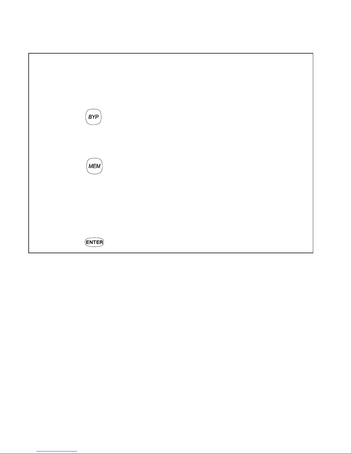
• The
[
MEM
]
Symbol if any al ar m s have occurred
• The
[
TRBL
]
Symbol if any troubles are occurring
• The
[
BYP
]
Symbol if zone s ar e by passed
and show the st at us of the “Status” Light (se e Fi gur e 2- 1, page 7)
2.3.2 Confidential Mode
The installer can program the keypads no t to display the status of your sys tem
automatically by changing the LED keypad from
Normal Mode
to Confidential
Mode. In Confidential Mode all the Symbols and Keypad Indicator Lights are
extinguished. Depending on how your keypad was programmed by the
installer, you must either press a button or enter your User Access Code to
activate Normal Mode.
2.3.3 Multiple-action
If your installer has enabled this feature, the LED Keypad will permit you to
complete more than one action without having to re-enter your
User
Access Code
. Press the button to exit the User Menu.
Page 9

10
User’s Manual
2.3.4 Backlight
The illumination behind the buttons can be modified to suit your needs.
2.4 P
ARTITIONED SYSTEM
Your installer can design your system to recognize up to four separate
protected areas. A separated system is called a Partitioned System, which
can be useful in situations where shared security systems are more
practical. For example, a company that has both an office area and a
warehouse ar ea can arm and di sa rm each area sepa ra te l y an d control the
access to each a rea. Ther efore, one p erson may ha ve ac cess t o onl y one
area, whereas another person may have access to all areas. Access to the
areas is determined by the
User Access Code
.
How do I modify the Backlight?
1) Enter your
[
ACCESS CODE
]
.
The keypad will emit a Confirmation Beep. The [
ACCESS
] Symbol will flash.
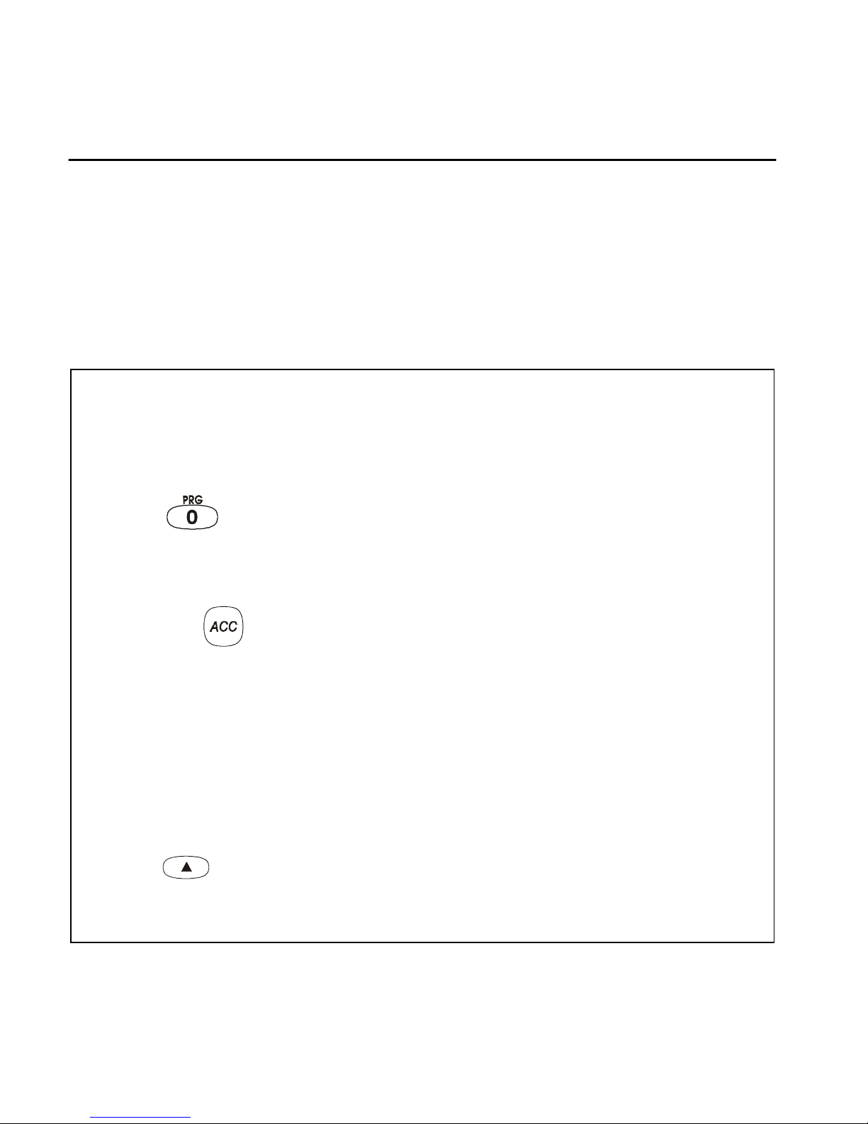
2) Press the button.
The keypad will emit a Confirmation Beep, the
[
PRG
]
Symbol will illuminate,
and the Numerical Symbol for the current setting will illuminate.
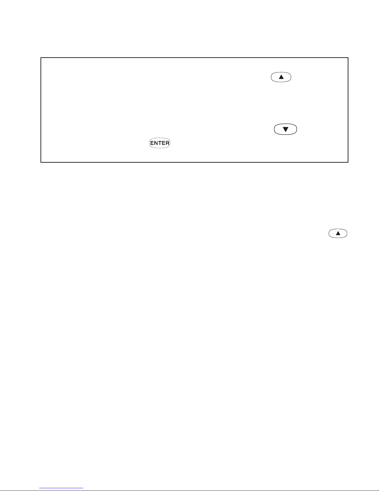
3) Use the and buttons to increase or decrease the illumination.
The range is between zero (Numerical Symbol
[10]
) and seven (Numerical
Symbol
[7]
) with seven being the brightest.
4) Press the button to save and exit.
Page 10

Digiplex LED Keypads 11
2.5 A
REA STATUS DISPLAY
In Area Status Disp lay you will be able to see the sta tus of the individual
areas in a
Partitione d System
(see section 2.4).
In Area Status Display the following will illuminate for the area selected:
• The Area Symbol (A1, A2, A3, and A4) if the area is armed. For example,
if you press , and Area 3 i s ar m ed,
[A3]
will illuminate.
• The Numerical Symbols repr esenting any open zones. For exa m pl e, if
zone 6 was ope n, th en t he Numerical Symb ol
[6]
would illuminate.
•The
[
MEM
]
Symbol if any alar m s have occurred
•The
[
TRBL
]
Symbol if any troubles are occurring
•The
[
STAY
]
Symbol if the area is Stay or Instant Armed
•The
[
FORCE
]
Symbol if the area is Force Armed
•The
[
BYP
]
Symbol i f zones are byp assed
•The state of the “S t atus” Ligh t
How do I see t he st at us of the zones?
1) Enter yo ur
[
ACCESS CODE
]
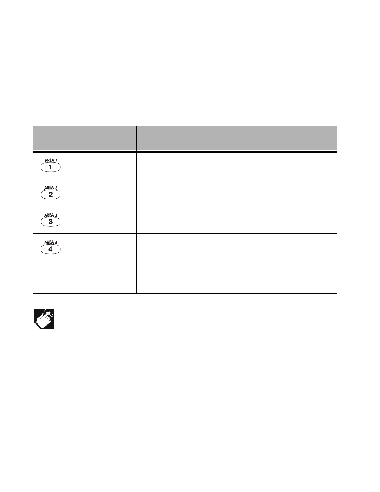
2) Press the numbered button corresponding to the desired area:
= Area 1 = Area 3
= Area 2 = Area 4
3) The keypad will emit a Confirmation Beep and will remain that Area’s
status for two minutes then return to Normal or Confidential Mode. You
can perform the next desired action from Area Status Display.
Page 11

12
User’s Manual
3.0 ARMING
When the system is armed, it will respond to any breach in the zones
according t o th e w ay eac h zone is prog ra mmed. For exam p le, if some one
opens a w indow that is armed, the s ystem can tri gger an alarm and alert
your Security Company.
3.1 E
XIT DELAY TIMER
When you arm the system, it will start the Exit Delay Timer to provide you
with enough tim e to ex it the prot ected area b efore th e syst em is ar med. Th e
Status Light
will flash green while the time elapses. The timer can be
assigned different time limits and the keypad can be programmed to beep
while the time elapses on the timer . Discuss these options with your installer .
3.2 R
EGULAR ARMING
This method is used for the everyday arming of the system. All zones
within the protecte d area m ust b e closed t o arm the sy stem. To check t he
status of the zones in each area, refer to section 2.5
Area Status Disp lay
.
Page 12

Digiplex LED Keypads 13
If enabled by your installer, the One-Touch Buttons (section 3.6) or
a keyswitch (se ct i on 3 .7 ) can also be used to ar m th e ar ea.
3.3 S
TAY ARMING
Stay Arming will partially arm your system to permit you to remain in the
protected area. Based on your instructions, your installer will program specific
zones as Stay Zones. These zones will not arm when you Stay Arm. For
example, you can arm your doors and windows at home without arming the
motion detectors so you will be protected while you sleep. Only
User Access
Codes
with the
Stay and Ins tant Arm
option enab led can Stay Arm the sy stem.
Also, see section 3. 8 Aut o-Armin g for anot her eve ryday armi ng option.
3.3.1 Stay Arming with Delay
Stay Arming with Delay
functions like Stay Arming except the installer can
program armed zones with an
Entry Delay Timer
. If these zones are
accidently triggered, the timer will start to allow you time to disarm the area(s).
How do I regular arm the system?
1) Enter yo ur
[
ACCESS CODE
]
.
The keypad will emit a Confirmation Beep. The
[
ACCESS
]
Symbol will flash.
2) Press the button.
If you have access to more than one area, press the Number Button
represen tin g th e ar ea you want to arm or
[0]
for all assigne d ar eas.
After the Confirmation Beep, the Exit Delay Timer will begin.
Page 13

14
User’s Manual
If enabled by your installer, the One-Touch Buttons (section 3.6) or
a keyswitch (se ct i on 3 .7 ) can also be used to ar m th e ar ea.
3.4 I
NSTANT ARMING
This feature is similar to
Stay Arming
. Instant Arming will partially arm your
system to permit you to remain in the protected area, but all zones, including the
entry/exit point, are changed to instant alarm zones. Therefore, if any armed
zone is breached, the alarm will instantly be triggered. Only
User Access Codes
with the
Stay and Instant Arm
option enabled will be able to Instant Arm.
3.4.1 Instant Arming with Delay
Insta n t Ar m in g wit h D el ay
functions l ike I nstant Arming except the i nst al ler
can program certain armed zones within the protected area(s) with an
Entry Delay Timer
. If these zones are accidently triggered, the timer will
start to allow yo u enough time to disa r m the are a( s) .
How do I Stay Arm?
1) Enter yo ur
[
ACCESS CODE
]
.
The keypad will emit a Confirmation Beep. The
[
ACCESS
]
Symbol will flash.
2) Press button.
If you have access to more than one area, press the Number Button
representing the area you want to Stay Arm or
[0]
for all assigned areas.
After the Confirmation Beep, the Exit Delay Timer will begin the countdown to arming.
Page 14

Digiplex LED Keypads 15
If enabled by your installer, the One-Touch Buttons (section 3.6) or
a keyswitch (se ct i on 3 .7 ) can also be used to ar m th e ar ea.
3.5 F
ORCE ARMING
Force Arming allows you to arm your system when specific zones are
open. Certain zones can be programmed by the installer to remain
unarmed when you initiate For ce Arming. Once the open zone is cl osed,
however, the system will then arm it as we ll. On ly
User Access Codes
with
the
Force Arm
option enabled can Force Arm the system. Also, see
section 3.8 Au to -A rm ing for another every day arming option .
This feature is commonly used when a motion detector is protecting an
area that is occupied by a keypad. During Force arming, the motion
detector will remain unarmed until you exit the area that it protects. The
system will th en arm the motion det ector.
How do I Instant Arm?
1) Enter yo ur
[
ACCESS CODE
]
.
The keypad will emit a Confirmation Beep. The
[
ACCESS
]
Symbol will flash.
2) Press the button.
If you have access to more than one area, press the Number Button
representing the area you want to Instant Arm or
[0]
for all assigned areas.
After the Confirmation Beep, the Exit Delay Timer will begin the countdown
to arming.
Page 15

16
User’s Manual
If enabled by your installer, the One-Touch Buttons (section 3.6) or
a keyswitch (se ct i on 3 .7 ) can also be used to ar m th e ar ea.
3.6 ONE-T
OUCH BUTTONS
At the touch a button you can view the
Area Status Display
(see section
2.5) for a
Partitioned System
(see section 2. 4) .
Pres s and hold:
Your ins talle r can also pr ogra m your sys tem to respond to cert ain featur es
with just a touch of a button. You will then have access to the following
features without using your
User Access Code
by pressing and holding the
desired button.
How do I Force Arm?
1) Enter yo ur
[
ACCESS CODE
]
.
2) Press the
button.
If you have access to more than one area, press the Number Button
representing the area you w ant to Force A rm or
[0]
for all assigned areas.
After the Confirmation Beep, the Exit Delay Timer will begin the countdown to arming.
Page 16

Digiplex LED Keypads 17
Pres s and hold:
For more information concerning these features, please refer to their
respective sections.
3.7 K
EYSWITCH ARMING
Your installer can add a keyswitch to arm and disarm your system. The
keyswitch can be programmed to
Regular, Stay, Force
, or
Instant Arm
, and
Disarm
a specific area. The keyswitch will also be programmed by the
installer to functi on as a Maintained or Momentary keyswitch.
3.7.1 Maintained Keyswitch
To arm the sy stem, place in the “on” posi t i on.
To disa r m the system, place in the “off” po sition.
3.7.2 Momentary keyswitch
To arm the system, place in the “on” position briefly then place it bac k in
the “off” position. Repeating this proc ess will disarm the s yst em .
Page 17

18
User’s Manual
3.8 A
UTO-ARMING
You can program area(s) to arm aut om at ically (if e nabled by your installer).
3.8.1 Timed Auto-Arming
If enabled, you can set the time that an ar ea will arm itself autom atically.
How do I set the Auto-Arming timer?
1) Enter yo ur
[
ACCESS CODE
]
.
The keypad will emit a Confirmation Beep. The
[
ACCESS
]
Symbol will flash.
2) Press the button.
The keypad will emit a Confirmation Beep. The
[
PRG
]
Symbol and Area
Symbol(s) will flash.
3) Press the button.
The
[
PRG
]
Symbol will flash and the
[
MEM
]
Symbol will illuminate.
If you have access to more than one area, the Area Symbols that you
have access to will illuminate in sequence. Press the Number Button
representing the area you want to arm.
4) Enter the
[
TIME
]
you want the area to be arm ed accor ding to the 24 -
hour clock (i. e. 9 a. m . is 09:00 and 9 p.m. is 21:0 0) .
The
[
MEM
]
Symbol will flash if a time is not already programm ed. The
[
PRG
]
Symbol, the Area Symbol of the chosen area, and the first number
of the previous time set will illuminate ([10] Symbol = zero).
5) Press the butt on t o sa ve and exit.
Page 18

Digiplex LED Keypads 19
To view the time set, instead of entering the
[
TIME
]
in Step 4, the first
number of the time you set will illuminate. Press the button to
illuminate the numbers one at a time (the Numerical Symbol
[10]
represents zero).
3.8.2 No Movement Auto-Arming
Your system can be programmed to send a report to the Security
Company a nd /or ar m the s yste m if the re is no ac tiv ity in the area du ring a
specified pe riod of time. Speak to your installer about th i s feat ure.
3.9 B
YPASS PROGRAMMING
The installer can program ce rtain zones with the byp ass option. This will
enable you to p rogram the system to bypa ss certain zo nes whe n you arm
the protected area. When a zone is bypassed, it will remain unarmed onc e
the system is armed. This option may be useful, for example, when you
are renovating part of the protected area. The system will keep the
bypassed zone(s) in memory until the area is armed. Once the area is
disarme d, the system will unb ypass the zones.
To bypass a zone:
The zone mus t ha ve t he Bypass option pr ogrammed by th e inst al le r.
Your
User Access Cod e
must be pro gram m ed to enable the By pass option.
Your
User Access Code
must have access to the zone’s
Area Assignment
.
Fire Zones cannot be bypassed.
Page 19

20
User’s Manual
3.9.1 Zone Bypass
3.9.2 Bypass Recall
Bypass Recal l re inst at es all the zones th at had Zone Bypass act ivat ed the
last time the system was armed.
If you have a
Partitioned System
, only the zones in the area(s)
assigned to your
User Access Code
will be affected.
How do I activate the Zone Bypa ss f eat ur e for a zone?
1) Enter your
[
ACCESS CODE
]
.
The keypad will emit a Confirmation Beep. The
[
ACCESS
]
Symbol will flash.
2) Press the button.
The
[
PRG
]
Symbol will illuminate and the
[
BYP
]
Symbol will flash.
3) Enter the t w o-digit number(s ) of the zone(s) you want to Bypass and
the corresponding number(s) will illuminate. If a zone’s number is
illuminated and you re-enter its number, the zone will unbypa ss and the
number will extinguish.
If a zone’s number does not illuminate and the keypad emits a Rejection
Beep, the zone may not have the Bypass feature accessible.
4) Press the button t o exit.
The
[
BYP
]
Symbol will remain illuminated.
Page 20
Digiplex LED Keypads 21
How do I activ ate B ypass Recall?
1) Enter yo ur
[
ACCESS CODE
]
.
The keypad will emit a Confirmation Beep. The
[
ACCESS
]
Symbol will flash.
2) Press the button.
The keypad will emit a Confirmation Beep. The
[
PRG
]
Symbol will illumi-
nate and the
[
BYP
]
Symbol will flash.
3) Press the button.
All zones bypassed during the last time the system was armed will
illuminate and will be bypassed.
4) If you w ish, re- enter t he zo ne ’s number to c hange a b ypass ed zo ne
to an unbypa ssed zone and vic e versa.
5) Press the button t o exit.
Page 21

22
User’s Manual
4.0 DISARMING
When the sy stem is disarm ed, the cont rol panel deac tivates the zone s so
the alarm will not be triggered if zones are breached. Any user can d isarm
the system unless their code ha s been assigned the
Arm Only
opti on.
4.1 E
NTRY DELAY TIMER
Based on your instructions the installer will program designated entry
points, such as the fr ont door or the garag e door, with an entry delay. This
delay will allow you enough time to ente r your code to disarm the sys tem
before the alarm is triggered.
4.2 D
ISARMING AN ARMED SYSTEM
You will only be able to disarm the area to which your
User Access Code
is
assigned.
User Acce ss C odes
with the
Arm Only
option w ill not be able to
disarm the sy st em .
Page 22

Digiplex LED Keypads 23
If enabled by your installer, the One-Touch Buttons (section 3.6) or
a keyswitch (se ct i on 3.7) can also be us ed t o di sa rm t he ar ea.
How do I disa rm the system?
If you are disarming a
Stay or Instant Armed
area, use Step 2 and Step 3.
For areas armed with the other arming features, use Step 1 and Step 2.
1) Enter through a designated en try.
The keypad will beep to acknowledge the entry, the Status Light will turn
red, and the Entry Delay Timer will begin the countdown.
2) Enter yo ur
[
ACCESS CODE
]
.
3) Press the button.
If you have access to more than one area, press the Number Button
representing the area you want to disarm
or
[0]
for all assigne d ar eas
.
The keypad will emit a Confirmation Beep.
How do I disarm the system if the alarm was accidentally triggered?
1) Enter yo ur
[
ACCESS CODE
]
.
2) Call yo ur Security Compan y quickly to advis e t hem of the false al arm.
Page 23

24
User’s Manual
4.3 A
LARM
M
EMORY DISPLAY
Your system will record all the alarms that occurred during the last armed
period. If an alar m was triggered in any area assigned to the keypad, the
[
MEM
]
Symbol will illuminate.
In case of a burglar alarm, leave the premises and call your
Security Company from a safe place.
The zones that were in alarm will remain in the Alarm Memory
until the next time th at are a i s ar m ed.
How do I vie w the list of the alarms that occurred?
When the
[
MEM
]
Symbol is illuminated:
1) Press the button.
The
[
MEM
]
Symbol will flash and the Numerical Symbols for each zone
whose alarm was triggered will illuminate.
2) Press the button t o ex it th e Alar m M em or y D isplay.
The
[
MEM
]
Symbol and Numerical Symbols will extinguish.
Page 24

Digiplex LED Keypads 25
5.0 ACCESS CODES
Access Codes are codes that will allow you and others to access the
system. T hes e cod es can be p ro gramm ed to pe rmi t a ccess to all o r som e
features and areas. The installer will program User Access Codes to be
four digits, si x digits, or var iable from one to six d igits in len gth. Each digi t
can be any val ue bet ween z ero and nine . If th e install er pr ogramm ed y our
system to acc ept a varia ble code leng th, you may have t o press the
button after entering their User Access Code. Only the
System Master
Code
cannot be less t han 4 digits.
5.1
KEYPAD LOCK-OUT
If a consec utive number of invalid codes are entered on the keypad, the
installer can program the sys tem to lock -out acc ess fro m the ke ypad for a
specified period of time.
5.2 E
RASING ACCESS CODES
To delete ex isting Acc es s Codes, pres s the button in steps 5, 6, and
7 in “How do I program Access Codes” starting on page 27. Once the
information is er ased, press the butto n to save and exit.
5.3 S
YSTEM
M
ASTER CODE
(default 123456)
The System Mast er Code wi ll give you access to all the features as well as
the ability to a dd, modify, or delet e any User Access C odes. We suggest
Page 25

26
User’s Manual
that you chan ge this code to p revent ot hers from access ing and c hanging
your op t ions with out author i zation.
How do I change the System Master Code?
1) Enter the curr en t
[
SYSTEM MASTER CODE
]
.
The keypad will emit a Confirmation Beep. The
[
ACCESS
]
Symbol will flash.
2) Press the button.
The keypad will emit a Confirmation Beep. The Area Symbols and the
[
PRG
]
Symbol will flash.
3) Press the button.
The keypad will emit a Confirmation Beep. The Area Symbol(s) and the
[
ACCESS
]
Symbol will illuminate. The
[
PRG
]
Symbol will flash.
4) Enter the num be rs
[0]
and
[1]
.
The keypad will emit a Confirmation Beep. The
[
PRG
]
Symbol and the
Numerical Symbol of the first number in the code will illuminate ([10] =
zero). The Area Symbols and
[
ACCESS
]
Symbol will extinguish.
5) Enter a
[
NEW CODE
]
.
The Numerical Symbols for the next numbers in the code will illuminate
one at a time as you enter the new code. When you have entered the
maximum number of digits, the keypad will emit a Confirmation Beep.
6) Press the button t o exit.
Page 26
Digiplex LED Keypads 27
5.4 U
SER ACCESS CODES
Your system can support up to 63 User Access Codes. All codes are given
a User Number bet w een 02 and 64 (Code 01 is th e
System Master Code
).
User Access Codes can be programmed with various options that will
allow you to control the access to your system. Only the
System Master
Code
and codes wit h the
Master
feature can pr ogram U ser Access Codes
with their User Options and Area Assignment.
How do I program a U s er Ac cess Code?
1) Enter yo ur
[
ACCESS CODE
]
System Master Code or User Access Code with the Master feature only.
2) Press to enter the
User Programming Menu
.
The Area Symbols of the areas assigned to your User Access Code and
the
[
PRG
]
Symbol will flash.
3) Press the button.
The Area Symbols of the areas assi gned to your User Access Code and the
[
ACCESS
]
Symbol will illuminate. The
[
PRG
]
Symbol will cont inue t o fla sh.
4) Enter the 2-digi t
User Number
(02 to 64) you want to program.
The
[
ACCESS
]
Symbol will flash for an unused code. If the code is used,
[
PRG
]
Symbol and first number of the code will illuminate. The
[
ACCESS
]
Symbol and the Area Symbols will extinguish.
5) Enter a User Code. If you do not want to change an existing one,
press until you reac h
User Options
.
The keypad will emit a Half Beep when it switches to User Options. Preexisting options will illuminate.
Page 27
28
User’s Manual
If the keypad emits a Rejection Beep, you may have chosen an existing
User Code or the Master Code used to modify or create the code does not
have access t o t he U s er Op tions or Area Assign m ent pr ogr am m ed.
To view the c ode programm ed, instea d of entering th e User Code in Step
5, the first number of the code programmed will illuminate. Press the
button and the numbers will illuminate one at a time as you press the
button (the Nu m er ic al Sym bol
[10]
represents zer o) .
In Table 1 and Table 2 the User Code Option or Area is considered ON
when the corresponding
Numerical Symbol
is illuminated. You turn
the
Numerical Symbols
ON and OFF by pressing the
Numerical
Buttons
on the keypad.
6) Program the User Options (see Table 1) by turning ON or OFF the
options. On ce the options are progra mmed, press to reach the
Area Assignment.
The keypad will emit a Half Beep when it switches to Area Assignment.
Pre-existing assignments will illuminate.
7) Program the Are a Assignment (see Table 2). Press to return to
User Options or press to save and exit.
The keypad will emit a Confi rmation Beep to conf irm the co de’ s accep tance.
Page 28

Digiplex LED Keypads 29
Table 1: User O ptions
Options on the U ser Access Codes that activate access to features.
Press option on/off Option Description
off off
Master feature disabled.
on off
Master feature enabled.
Modifies User Code only.
on on
Full Master feat ur e enabled.
Create or modify other User Codes, User
Options, and Area Assignment according to its
own User Op tions and Area Assign m ent .
off
Duress f eature dis abled.
on
Duress f eat ur e enabled.
Can arm, disarm, and send a silent alarm to
the Security Company. For use when someone
forces yo u to arm or disarm areas.
off
Bypas s f eature disabled.
on
Bypass feat ur e ena b led.
Can deactivate zones usin g t he Bypass featu r e
off
Arm Only feature disabled.
on
Arm Only feature enabled.
Can arm assigned areas, but
CANNOT
disarm.
Page 29
30
User’s Manual
off
Stay & Instan t Arm fe at ur e di sa bl ed.
on
Stay & In stant Arm featu re enabled
.
Can Stay or Inst ant Arm the system
off
Force Arm fe at ur e di sa bl ed.
on
Force Ar m feature enabled.
Can Force Arm the sys te m .
off
User Access Code obeys the keypad's area
assignment in a Partitioned System.
When you enter your User Access Code, the
keypad will p ermi t access o nly t o a reas it c ontro ls.
on
Keypad obeys the User Access Code's area
assignment in a Partitioned System.
The keypad will permit access to all the areas
assigned to the User Access Code regardless
which area s t he keypad control s.
Press option on/off Option Description
Page 30
Digiplex LED Keypads 31
Table 2: Area Assignment
In a
Partitioned System
the system can be divided into four distinct
protected a reas . Pro gramm ing acce ss to a spec ific a rea or area s is ca lled
Area Assignment. User Access Codes are only able to perform actions
(arming, dis ar m in g, et c. ) in th e ar ea(s) the code is assi gned.
When the area' s number is OF F, the User Acce ss Code does not
have access t o t hat pr ot ected area.
Press button on/off Area Assignment
on
Access to Area 1
on
Access to Area 2
on
Access to Area 3
on
Access to Area 4
All four buttons off Controls PGMs only (if PGMs are
programmed by the installer).
Page 31

32
User’s Manual
6.0 TROUBLE DISPLAY
When your s ystem experiences p roblems or is tam pered with, the
[
TRBL
]
Symbol will illuminate. Most of the trouble conditions will be programmed
by your installer to be reported directly to your Security Company (if
connected). The keypad will only display troubles that occur in the area(s)
to which the keypad has been assigned.
Pote nti al t rou bl es ha ve b e en so rt ed i nt o e igh t g r ou ps . Th e Gr ou p head i ng s
are listed below with a brief explanation of the potential troubles sorted
within each group.
We strongly suggest that you simply inform your Security
Company of the trouble and allow them to service your
system.
How do I view the T r ouble Display?
1) The
[
TRBL
]
Symbol illuminates.
2) Press the button.
The
[
TRBL
]
Symbol will flash and the Numerical Symbol(s) representing
Group heading number(s) will illuminate.
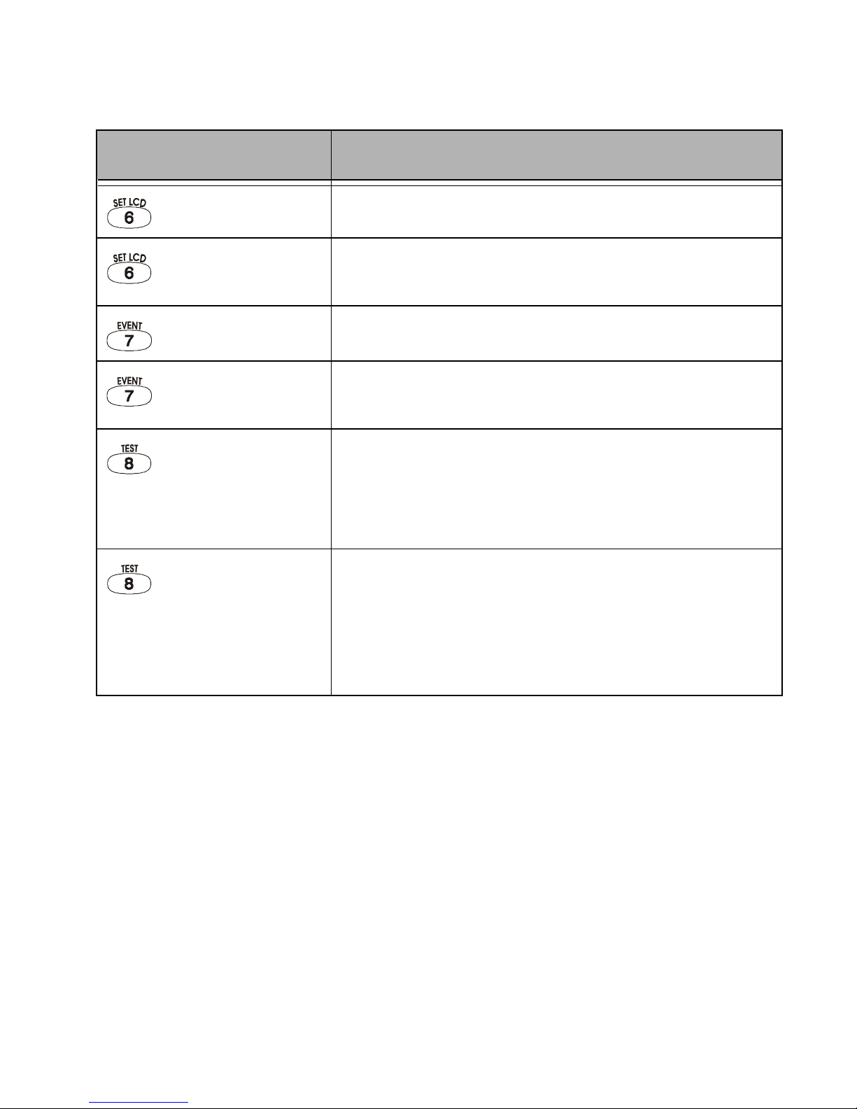
3) Press the Numerical Symbol corresponding to the G ro up heading to
view the sp eci fic trouble.
Page 32

Digiplex LED Keypads 33
If your keypad is in
Confidential Mode (see section 2.3.2),
the
[
TRBL
]
Symbol will not illuminate until you enter your User Access
Code or press a butt on dependin g on how the keyp ad was
programmed.
6.0.1 Group [1]: System
Trouble [1]: AC Failure
The control panel has detected a power failure. This means that your
system is running on the back-up battery. The
AC Light
on your keypad will
be turned off during a power failure. If this Trouble occurs when your
establishment is not experiencing a power failure, call your Security
Company fo r re pairs.
Trouble [2]: Battery Trouble
This means the back-up b attery is disconn ected, needs to be recharged,
or replaced.
Trouble [3]: AUX Current Limit
Devices con nected to t he control panel h ave excee ded curr ent limits. The
Auxiliary Ou tput w ill shutdown until the tro ubl e has been rectified.
Trouble [4]: Bell Current Limi t
The bell or siren connected to the control panel has exceeded current
limits. The Bell/Siren Output will shutdown until the trouble is rectified.
Trouble [5]: Bell Absent
The control pan el has det ected that the bell or sire n is not con nected.
Trouble [6]: ROM check Er ro r
The control pan el re gi st er s a m em ory error.
Page 33

34
User’s Manual
6.0.2 Group [2]: Communicator
Trouble [1]: TLM (Teleph one Line Monitor)
The control pa nel is unable to access the t el eph one line.
Troubles [2] to [5]:
[2] Fail to Communicate 1
[3] Fail to Communicate 2
[4] Fail to Communicate 3
[5] Fail to Communicate 4
The contr ol panel has tried all assigned telephone nu m bers and has fa iled
to communicate with the Security Company.
Trouble [6]: Fail to Communicate PC
The control panel is unable t o communicate wi th the Security C ompany's
diagnostic software.
6.0.3 Group [3]: Modules Trouble
Trouble [1]: Module Tam per
The control pa nel registers that someone ha s triggered the t amper switch
on a module.
Trouble [2]: ROM Check E rror
The control pa nel re gi st er s a m em ory error in a modu le.
Trouble [3]: TLM Trouble
A module is una ble to access the telephone line.
Page 34

Digiplex LED Keypads 35
Trouble [4]: Fail to Communicate
A module has fa iled to comm unicate with the Secur i ty Com pany.
Trouble [5]: Printer Trouble
The control panel registers a problem with the printer. Check printer for
problems (p aper jam, no paper, no power, etc. ) be fo re cal lin g i nst all er.
Trouble [6]: AC Failure
Module pow er fail ur e.
Trouble [7]: Battery Failure
Module's batt er y i s di sc onnected, needs t o be recharged, or replaced.
Trouble [8]: Supply Output
Module has exceeded current lim i ts.
6.0.4 Group [4]: Bus Troubles
Trouble [1]: Missing Keypad
A keypad is no lon ger communicating w ith the control panel.
Trouble [2]: Missing Module
A device is no longer communicat ing w i th th e control panel.
Trouble [6]: General Failur e
No communication between the devices and the control panel.
Trouble [7]: Bus Overload
Too many devices are connected on the Bus.
Page 35

36
User’s Manual
Trouble [8]: Bus Communication Error
The Bus is having difficulty communicating between the devices and the
control pane l.
6.0.5 Group [5]: Zone Tamper
The Numerical Symbols for the zone or zones that have been tampered
with will be illuminated.
6.0.6 Group [6]: Zone Low Battery
If a wireless device 's batte ry needs to be r eplaced, the Num erical Symbol
for the zone that it is assigned to will be illuminated. Also, the yellow light
on the device will flash to indicate this trouble.
6.0.7 Group [7]: Zone Fault
A smoke detec tor is experiencing a wiring problem, needs to be cleane d,
or a wireless de vi ce is no longer comm unicating with its rec ei ver.
Page 36

Digiplex LED Keypads 37
6.0.8 Group [8]: Clock Loss
The time and date have been reset to the default.
This is the only
Trouble tha t we r ecommend that you correct.
How do I reset th e tim e and date?
When the
[
TRBL
]
Symbol flashe s and the
[8]
Symbol is illuminated.
1) Press the button.
The
[
TRBL
]
Symbol will flash, the
[
PRG
]
Symbol and a Numerical Symbol
are illuminated.
2) Enter t he hour and m inut es according to a 24-hour clock (i.e. 9 a.m.
is 09:00 and 9 p. m . is 21: 00) .
The default tim e w i ll be illum i nat ed one number at a time as you
enter the correct time. The keypad will emit a Half Beep when it
accepts the new time and sw itch es to programmi ng t he date.
3) Enter the correct date according to yyyy/mm/dd.
The default dat e w i ll be illum i nat ed one number at a time as you
enter the cor re ct dat e. The keypad will emi t a Co nf i rmat i on B eep
when it accepts the new date.
4) Press the button t o exit the menu.
If there are other Troubl es with the sy stem, the
[
TRBL
]
Symbol will
remain illuminated until they are resolved. Contact your Security
Company to effect repairs.
Page 37

38
User’s Manual
7.0 ADDITIONAL FEATURES
7.1 P
ANIC ALARMS
Your system can be programmed to send an alarm to your Security
Company to alert them that you require em ergency assistance w hen you
press a pre-determined combination of Number Buttons on the keypad.
The three Panic Alarms can be programmed to request help from the
police, a medic al fa cility, the fire department, or anyon e you wish. Ask your
installer about programming these features in your system.
Emergency Panic
When you press the and buttons at the same time and hold
them for two seconds, the system will generate an alarm. The alarm can
be programmed to be either silent or audible according to your preference.
Auxiliary Panic
When you press the and buttons at the same time and hold
them for two seconds, the system will generate an alarm. The alarm can be
programme d t o be either a si l ent or audible acco r di ng to your prefer ence.
Fire Panic
When you press the and buttons at the same time and hold
them for two seconds, the system will generate an alarm. The alarm can be
programme d t o be either a si l ent or audible acco r di ng to your prefer ence.
Page 38

Digiplex LED Keypads 39
7.2 P
ROGRAMMING CHIME ZONES
You c an program the key pads to em it a rapid, i ntermitten t beep w henever
designated zones are opened or only when opened between certain
hours. These zones are referred to as Chime Zones. Each keypad must be
Chime programmed separately. Your installer can program your Chimed
zones to also beep upon closure.
7.2.1 Activating a Chime Zone
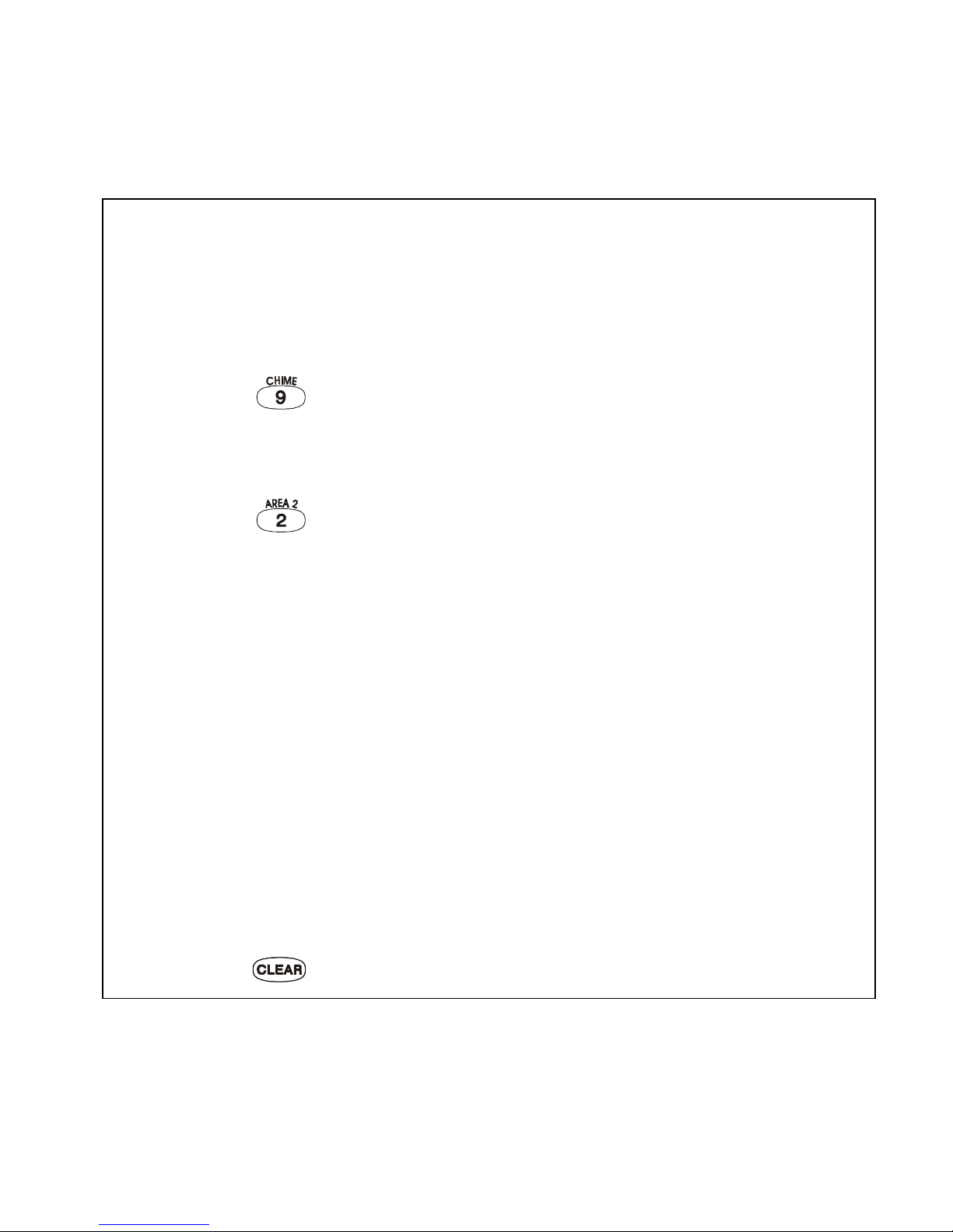
How do I program a keypad to beep eve ry time a zone opens?
1) Enter yo ur
[
ACCESS CODE
]
.
The keypad will emit a Confirmation Beep. The
[
ACCESS
]
Symbol will flash.
2) Press the button t o enter the Chiming M enu.
The keypad will emit a Confirmation Beep. The
[
PRG
]
Symbol and Area
Symbol(s) will flash.
3) Press the button.
The keypad will emit a Confirmation Beep. The
[
PRG
]
Symbol and any
already Chimed zones will illuminate.
4) Enter the two-digit zone number(s) you want to designate as Chimed.
The keypad will emit a Confirmation Beep and the Numerical Symbol(s)
corresponding to the zone(s) will illuminate. If you re-enter the number of
an illuminated Numerical Symbol, the corresponding zone will unchime
and the Numerical Symbol will extinguish.
5) Press the button t o exit.
Page 39
40
User’s Manual
7.2.2 Setting a Chime Zone ti me period
How do I program all the keypad’s Chimed zones to beep only
when they open between specific hours?
1) Enter yo ur
[
ACCESS CODE
]
.
The keypad will emit a Confirmation Beep. The
[
ACCESS
]
Symbol will flash.
2) Press the button t o enter the Chiming M enu.
The keypad will emit a Confirmation Beep. The
[
PRG
]
Symbol and Area
Symbol(s) will flash.
3) Press the button.
The keypad will emit a Confirmation Beep. The
[
PRG
]
Symbol and a
Numerical Symbol will illuminate. The Numerical Symbol represents the
first number of the previously set time ([10] Symbol = zero). When the
[A2] and [A3] Symbols flash, no time is set.
4) Enter the time you want all Chimed zones to
start
beeping when
they open ac cording to the 24-ho ur cl ock (i.e . 9 a.m. is 09: 00 and 9
p.m. is 21:00 ).
The keypad will emit a Half Beep.
5) Enter the time you want all Chimed zones to
stop
beeping when they
open according to the 24-hour cl ock. If you want the C hi m ed zones to
beep every time they open, ent er the same time set in Step 4.
The keypad will emit a Confirmation Beep.
6) Press the button to exit .
Page 40

Digiplex LED Keypads 41
7.3 Q
UICK FUNCTION BUTTONS
You will only need to use the Quick Function Buttons upon your installer or
Security Company's request. Only the
System Master Code
or
User Access
Codes
with the
Master
feature enabled will be able t o access these functi ons.
7.4 P
ROGRAMMABLE OUTPUTS
(PGMS)
Your Di gip le x syst em in clu des two or more program m able outputs (PGMs) that
can be progra mmed by your installer. A PGM triggers when a pr edetermined
event or series of events occurs in your system. The PGMs can be
programmed to reset smoke alarms, turn on light switches, open or close
garage doors and much more. Ask your installer about this useful feature.
How do I access the Quick Function Buttons?
1) Enter your
[
SYSTEM MASTER CODE
] or [
ACCESS CODE
]
with Master featur e
2) Press the button.
3) Press one of the foll owi ng for the system to:
button:
send
a test report to the Security Company
button:
call
the Security C om pany's diagnost ic software.
button:
answer
the Security C om pany's diagnosti c software.
button:
cancel
the communication with the Security Company.
Page 41
42
User’s Manual
8.0 FIRE AND BURGLAR ALARMS
8.1 S
TANDARD FIRE ZONE
During a fire alarm, the bell/siren will emit an intermittent sound (
BEEP
-
BEEP-BEEP
) until silenc ed or reset. If the zo ne is a S tand ard Fir e Zone , the
system ca n imm ediately send an al er t to yo ur S ec urity Company.
The Fire Zone ma y reset itself once the problem h as cleared.
If it does not, simultaneously press and hold the and
buttons for two seconds or speak to your installer.
8.2 D
ELAYED FIRE ZONE
During a fire alarm, the bell/siren will emit an intermittent sound (
BEEP
-
BEEP-BEEP
) until silenced or reset. If the zone is a Delayed Fire Zone, there
is an automatic delay before the system contacts the Security Company
(see Figure 8-1) . Th is will pre ve nt unnecessary repor t in g of fa ls e alarms.
If you are unable to cancel the fire alarm, the system will send an
alert (if connected). Call your Security Company to advise them of
the false alarm.
How do I disarm the system if it was accidentally trig ger ed?
1) Enter yo ur
[
ACCESS CODE
]
.
2) Call your S ecurit y Company quickly to advise them of the false alarm.
Page 42
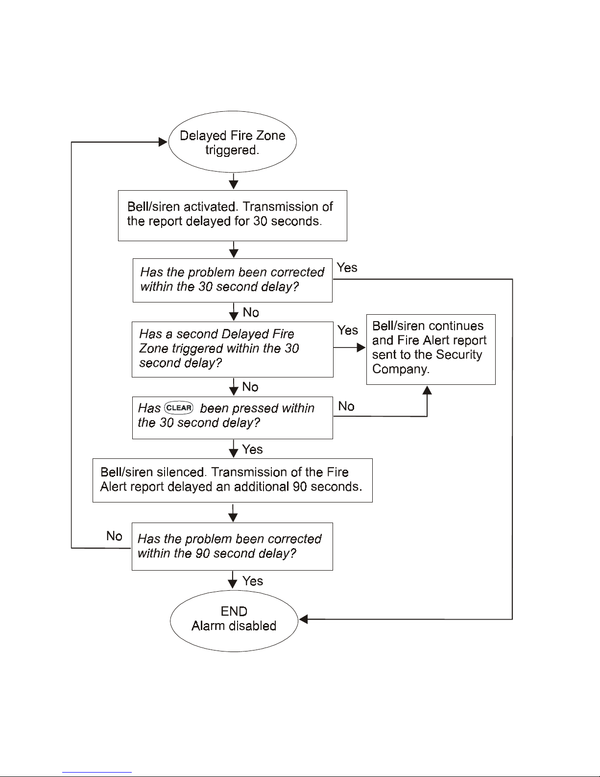
Digiplex LED Keypads 43
Figure 8-1: Delayed Fire Zone
Page 43
44
User’s Manual
The Fire Zone may reset itself once the smoke has cleared. If
it does not, sim ul t ane ously press and ho ld th e an d
buttons for two se conds or speak to your inst al le r.
8.3 F
IRE SAFETY TIPS
During a fire, time is the biggest enemy and every second counts! What
should you do to pre par e i n case of a fire in your hom e or business?
1) Remind everyone to escape first, then call for help.
2) Develop a fire escape plan and des ig nate a meeting plac e ou ts i de.
3) Practice the escape plan freq uen t ly.
4) Plan two way s to escape from ever y ro om , if pos si bl e.
5) Practice feeling the way out with eyes closed.
6) Remind everyone
never
to stand up during a fire, always crawl low
under the smoke and keep mou t hs covered.
7) Instruct eve ryone nev er to retur n to a b urning b uild ing for any rea son; it
may cost them t heir lif e.
8) Check smoke alarms regular ly; working smoke alarms dramatically
increase e ver yone's chances of sur vi vi ng a fire.
What do I do if the fire alarm is set off accidentally?
1) Press the butt on wi t hi n 30 seconds of the alar m .
2) Clear the problem from the area.
3) If problem remains, the alarm will sound again. Press again.
These steps will instruct the system to delay reporting the alert to the
Security Company.
Page 44

Digiplex LED Keypads 45
8.4 M
INIMIZING HOME FIRE HAZARDS
How can you avoid the three mos t com mon causes of fire s at hom e?
1) Never leave cooking food unat t ended. Cooking fir es of t en result from
unattended cooking and human error, rath er tha n m echanical failure .
2) Stay alert when smoki ng. C areless smokin g i s t he leading cau se of fire
deaths. S moke de tecto rs and smo lder- resi s tant bed ding and up holst ered
furnitur e are significant fire det err ents.
3) Maintain your heating system. Heating is the second leading cause of
residential fire s. Ho wever, heating fires are a larger pr oblem in single
family home s th an i n apartments. Unli ke apartments, the heating
systems in si ngle family homes are oft en not professi onally ma i ntained.
4) Since fires produce smoke and deadly gases that can overcome occupant s
while they sleep, smoke detectors should be installed outside each
separate sleeping area in the immediate vicinity of the bedrooms and on
each additional story of the family livin g unit, including basements.
8.5 B
URGLAR ALARM
If your armed system is breached, the burglar alarm devices specific to
your system will be triggered. If your keypad is in
Normal Mode
:
• The
Status Light
and
Area Symbol
of the area in alarm may flash red
• The keypad m ay beep
• The
[
MEM
]
Symbol will illuminate
• The bell or sire n m ay b e acti vated
• The zones in alarm will be recorded in the
Alarm Memory Display
.
In case of a burglar alarm, leave the premises and call your
Security Company from a safe place.
Page 45

46
User’s Manual
9.0 TESTING AND MAINTENANCE
9.1 B
URGLAR ALARM TESTING
Two people are needed to complete this test. One person will watch the
keypad while the other person walks around and opens the zones (i.e.
open the doors and windows that are protected, walk in the path of the
motion detect ors, etc.). The N umerical Sym bols for the opene d zones will
illuminate w hen opened . If a zone doe s not registe r, contact your installer.
Use
Area Status Display
to view the open zones in other areas assigned to
the keypad. Your installer will provide details on the best way to test your
particular sy st em .
9.2 F
IRE ALARM TESTING
Do
NOT
use an o pen flam e or bur ning mat erials t o t est y our fire d etec tion
devices. Your installer will provide details on the best way to test your
particular sy st em .
9.3 S
YSTEM MAINTENANCE
Under normal use your system requires virtually no maintenance other
than regular testing. It is recommended that your installer change the
battery ever y t hr ee years.
Page 46

Digiplex LED Keypads 47
9.4 S
YSTEM TEST
Speak to you r installer before conducting a syst em test since the sys tem
must be programmed to respond to the test instructions. It is normally
recommend ed that you co nduct the syst em test once a week, but con tact
your installe r for ins tructions concer ning your particular system.
How do I conduct the system test ?
1) Call Security Company to advise them that you are testing the system.
2) Enter yo ur
[
ACCESS CODE
]
.
3) Press the button.
The system will test all its connections and can send a report to your
Security Company. If the system detects a problem, the
[
TRBL
]
Symbol
will illuminate (see section 6.0). Call your installer for repairs.
Page 47

48
User’s Manual
10.0 SYSTEM CHECKLIST
Important: Keep this information in a secure location.
10.1 Z
ONE DESCRIPTION
Is this a Partitione d Sys t em ? Yes N No N
Area 1 = _______ __________________________________ _
Area 2 = _______ __________________________________ _
Area 3 = _______ __________________________________ _
Area 4 = _______ __________________________________ _
Place a > to indicate the options an d ar eas enabled for that zone (if any).
Zone # and
Description
Area
1 2 3 4
Byp Stay Force 24Hr.
Entry
Delay
01:___________
NNNN N N N N
____
02:___________
NNNN N N N N
____
03:___________
NNNN N N N N
____
04:___________
NNNN N N N N
____
05:___________
NNNN N N N N
____
06:___________
NNNN N N N N
____
07:___________
NNNN N N N N
____
08:___________
NNNN N N N N
____
Page 48

Digiplex LED Keypads 49
09:___________
NNNN N N N N
____
10:___________
NNNN N N N N
____
11:___________
NNNN N N N N
____
12:___________
NNNN N N N N
____
13:___________
NNNN N N N N
____
14:___________
NNNN N N N N
____
15:___________
NNNN N N N N
____
16:___________
NNNN N N N N
____
17:___________
NNNN N N N N
____
18:___________
NNNN N N N N
____
19:___________
NNNN N N N N
____
20:___________
NNNN N N N N
____
21:___________
NNNN N N N N
____
22:___________
NNNN N N N N
____
23:___________
NNNN N N N N
____
24:___________
NNNN N N N N
____
25:___________
NNNN N N N N
____
26:___________
NNNN N N N N
____
27:___________
NNNN N N N N
____
28:___________
NNNN N N N N
____
Zone # and
Description
Area
1 2 3 4
Byp Stay Force 24Hr.
Entry
Delay
Page 49

50
User’s Manual
29:___________
NNNN N N N N
____
30:___________
NNNN N N N N
____
31:___________
NNNN N N N N
____
32:___________
NNNN N N N N
____
33:___________
NNNN N N N N
____
34:___________
NNNN N N N N
____
35:___________
NNNN N N N N
____
36:___________
NNNN N N N N
____
37:___________
NNNN N N N N
____
38:___________
NNNN N N N N
____
39:___________
NNNN N N N N
____
40:___________
NNNN N N N N
____
41:___________
NNNN N N N N
____
42:___________
NNNN N N N N
____
43:___________
NNNN N N N N
____
44:___________
NNNN N N N N
____
45:___________
NNNN N N N N
____
46:___________
NNNN N N N N
____
47:___________
NNNN N N N N
____
48:___________
NNNN N N N N
____
Zone # and
Description
Area
1 2 3 4
Byp Stay Force 24Hr.
Entry
Delay
Page 50

Digiplex LED Keypads 51
Exit Delay:
Area 1 is ___________ seconds .
Area 2 is ___________ seconds .
Area 3 is ___________ seconds .
Area 4 is ___________ seconds .
The entry delay s appear in the
Zone Description
section.
10.2 A
CCESS CODES
For security reasons, write only the user’s name and not his or her access code.
Place a
> in the squares to identify which options are enabled for the code.
System uses: 4-Digit Codes
N
6-Digit Codes
N 1 to 6 Digit Codes N
User # and Name
Area
1 2 3 4
Master
Full
Master
Byp Stay Force
Arm
Only
Duress
Keypad
obeys
code
System Master Code 1 2 3 4
>>>> >
02:
____________ ____
NNNNNNNN
03:
____________ ____
NNNNNNNN
04:
____________ ____
NNNNNNNN
05:
____________ ____
NNNNNNNN
06:
____________ ____
NNNNNNNN
07:
____________ ____
NNNNNNNN
08:
____________ ____
NNNNNNNN
09:
____________ ____
NNNNNNNN
10:
____________ ____
NNNNNNNN
Page 51

52
User’s Manual
11:
____________ ____
NNNNNNNN
12:
____________ ____
NNNNNNNN
13:
____________ ____
NNNNNNNN
14:
____________ ____
NNNNNNNN
15:
____________ ____
NNNNNNNN
16:
____________ ____
NNNNNNNN
17:
____________ ____
NNNNNNNN
18:
____________ ____
NNNNNNNN
19:
____________ ____
NNNNNNNN
20:
____________ ____
NNNNNNNN
21:
____________ ____
NNNNNNNN
22:
____________ ____
NNNNNNNN
23:
____________ ____
NNNNNNNN
24:
____________ ____
NNNNNNNN
25:
____________ ____
NNNNNNNN
26:
____________ ____
NNNNNNNN
27:
____________ ____
NNNNNNNN
28:
____________ ____
NNNNNNNN
29:
____________ ____
NNNNNNNN
30:
____________ ____
NNNNNNNN
User # and Name
Area
1 2 3 4
Master
Full
Master
Byp Stay Force
Arm
Only
Duress
Keypad
obeys
code
Page 52

Digiplex LED Keypads 53
31:
____________ ____
NNNNNNNN
32:
____________ ____
NNNNNNNN
33:
____________ ____
NNNNNNNN
34:
____________ ____
NNNNNNNN
35:
____________ ____
NNNNNNNN
36:
____________ ____
NNNNNNNN
37:
____________ ____
NNNNNNNN
38:
____________ ____
NNNNNNNN
39:
____________ ____
NNNNNNNN
40:
____________ ____
NNNNNNNN
41:
____________ ____
NNNNNNNN
42:
____________ ____
NNNNNNNN
43:
____________ ____
NNNNNNNN
44:
____________ ____
NNNNNNNN
45:
____________ ____
NNNNNNNN
46:
____________ ____
NNNNNNNN
47:
____________ ____
NNNNNNNN
48:
____________ ____
NNNNNNNN
49:
____________ ____
NNNNNNNN
50:
____________ ____
NNNNNNNN
User # and Name
Area
1 2 3 4
Master
Full
Master
Byp Stay Force
Arm
Only
Duress
Keypad
obeys
code
Page 53

54
User’s Manual
51:
____________ ____
NNNNNNNN
52:
____________ ____
NNNNNNNN
53:
____________ ____
NNNNNNNN
54:
____________ ____
NNNNNNNN
55:
____________ ____
NNNNNNNN
56:
____________ ____
NNNNNNNN
57:
____________ ____
NNNNNNNN
58:
____________ ____
NNNNNNNN
59:
____________ ____
NNNNNNNN
60:
____________ ____
NNNNNNNN
61:
____________ ____
NNNNNNNN
62:
____________ ____
NNNNNNNN
63:
____________ ____
NNNNNNNN
64:
____________ ____
NNNNNNNN
User # and Name
Area
1 2 3 4
Master
Full
Master
Byp Stay Force
Arm
Only
Duress
Keypad
obeys
code
Page 54

Digiplex LED Keypads 55
10.3 S
PECIAL BUTTONS AND FEATURES
One-Touc h Butt ons:
Place a
>if the One-Touch Button is activated.
Panic Alarms:
Place a
>if the Panic But t on is activated & if alarm is sile nt or audibl e.
N Stay Arming N Bypass Programming
N Force Arming
N In s tant Ar ming
N Regular Arming
N Backlight
N Disarm Stay or Instant Arming
N &
Emergency or__________ __ NSilent NAudible
N &
Auxiliary or______________ NSilent NAudible
N &
Fire or______ ____________ NSilent NAudible
Page 55

56
User’s Manual
PGMs:
10.4 O
THER INFORMATION
Installed By:__________________________ Date:_________________
Service provided by:___________________ Tel:___________________
Monitoring Stat i on : __ __________________ Tel: _______________ ____
Your account number is: _______________________ ________________
Alarm transformer location:_______________ on circuit #:_____________
Location of Telephone Connections: ______________________________
PGM When this occurs: This is activated:
1 _______________________ _______________________
2 _______________________ _______________________
3 _______________________ _______________________
4 _______________________ _______________________
5 _______________________ _______________________
Page 56

Warranty
The Seller warrants its products to be free from defects in materials and
workmanship under normal use for a period of one year. Except as specifically
stated herein, all express or implied warranties whatsoever, statutory or
otherwise, including without limitation, any implied warranty of merchantability
and fitness for a particular purpose, are expressly excluded. Because Seller
does not install or connect the products and because the products may be
used in conjunction with products not manufactured by Seller, Seller cannot
guarantee the performance of the security system. Seller obligation and
liability under this warranty is expressly limited to repairing or replacing, at
Seller's option, any product not meeting the specifications. In no event shall
the Seller be liable to the buyer or any other person for any loss or damages
whether direct or indirect or consequential or incidental, including without
limitation, any damages for lost profits, stolen goods, or claims by any other
party caused by defective goods or otherwise arising from the improper,
incorrect or otherwise faulty install ation or use of the merchandise sold.
Page 57

 Loading...