

Page 1
Section [001] : Substation 1 Partition Assignment
Option OFF ON
[1] Partition 1
N Disabled
U Enabled
[2]
Partition 2
N Disabled
U Enabled
[3]
Partition 3
N Disabled
U Enabled
[4]
Partition 4
N Disabled
U Enabled
[5]
Partition 5
N Disabled
U Enabled
[6]
Partition 6
N Disabled
U Enabled
[7]
Partition 7
N Disabled
U Enabled
[8]
Partition 8
N Disabled
U Enabled
Section [002] : Substation 2 Partition Assignment
Option OFF ON
[1] Partition 1
N Disabled
U Enabled
[2]
Partition 2
N Disabled
U Enabled
[3]
Partition 3
N Disabled
U Enabled
[4]
Partition 4
N Disabled
U Enabled
[5]
Partition 5
N Disabled
U Enabled
[6]
Partition 6
N Disabled
U Enabled
[7]
Partition 7
N Disabled
U Enabled
[8]
Partition 8
N Disabled
U Enabled
Section [003] : Substation 3 Partition Assignment
Option OFF ON
[1] Partition 1
N Disabled
U Enabled
[2]
Partition 2
N Disabled
U Enabled
[3]
Partition 3
N Disabled
U Enabled
[4]
Partition 4
N Disabled
U Enabled
[5]
Partition 5
N Disabled
U Enabled
[6]
Partition 6
N Disabled
U Enabled
[7]
Partition 7
N Disabled
U Enabled
[8]
Partition 8
N Disabled
U Enabled
paradox.com
Printed in Canada- 12/2007
DGPLSN4-EP02
Listen-In Module
DGP-LSN4 V1.1
Programming Guide
Section [004] : Substation 4 Partition Assignment
Option OFF ON
[1] Partition 1
N Disabled
U Enabled
[2]
Partition 2
N Disabled
U Enabled
[3]
Partition 3
N Disabled
U Enabled
[4]
Partition 4
N Disabled
U Enabled
[5]
Partition 5
N Disabled
U Enabled
[6]
Partition 6
N Disabled
U Enabled
[7]
Partition 7
N Disabled
U Enabled
[8]
Partition 8
N Disabled
U Enabled
Section [005] : General Options1
Option OFF ON
[1] Module Tamper Input
U Disabled
N Enabled
[2] Telephone Line Monitoring
U Disabled
N Enabled
[3] Volume Bypass
N Disabled
U Enabled
[4] Continuous Recording
U Disabled
N Enabled
[5] Bypass Siren on Communication
N Disabled
U Enabled
[6] Locate Feedback on Substations
U Disabled
N Enabled
[7] Response Connection Code
U Direct
N Press *
[8] Call Back Connection
N Disabled
U Enabled
Section [006] : General Options 2
Option OFF ON
[1] Substation 1 Anti-tamper Switch
U Disabled
N Enabled
[2] Substation 2 Anti-tamper Switch
U Disabled
N Enabled
[3] Substation 3 Anti-tamper Switch
U Disabled
N Enabled
[4] Substation 4 Anti-tamper Switch
U Disabled
N Enabled
[5] Background Music Input
U Disabled
N Enabled
[6] User Phoneline Menu Selection
U User
N Monitoring
[7] Monitoring Station Phoneline Menu
Selection
N User
U
Monitoring
[8] User Phoneline Default Menu N Arm/
Disarm
UListen-In
Section [007] :Connection Options 1
Option OFF ON
[1] Zone Alarm starts Listen-in Mode
N Disabled
U Enabled
[2] Fire Alarm starts Listen-in Mode
N Disabled
U Enabled
[3] Duress Alarm starts Listen-in Mode
N Disabled
U Enabled
[4] Panic Police starts Listen-in Mode
N Disabled
U Enabled
[5] Panic Medical starts Listen-in Mode
N Disabled
U Enabled
[6] Panic Fire starts Listen-in Mode
N Disabled
U Enabled
[7] Zone Tamper starts Listen-in Mode
U Disabled
N Enabled
[8] Zone Supervision starts Listen-in Mode
U Disabled
N Enabled
Section [008] : Connection Options 2
Option OFF ON
[1] Zone Fire Loop Trouble starts Listen-In
Mode
U Disabled
N Enabled
[2] Module Tamper starts Listen-in Mode
U Disabled
N Enabled
[3] Door Force Alarm starts Listen-In
Mode
U Disabled
N Enabled
[4] Bus Fault starts Listen-in Mode
U Disabled
N Enabled
[5] Police Code starts Listen-In Mode
U Disabled
N Enabled
[6] - [8] Future use N N/A N N/A
Section [009] : Substation 1 Page Options
Option OFF ON
[1] N/A N N/A N N/A
[2] Substation 1 can page Substation 2 N Disabled
U Enabled
[3] Substation 1 can page Substation 3 N Disabled
U Enabled
[4] Substation 1 can page Substation 4 N Disabled
U Enabled
[5] - [8] Future Use N N/A N N/A
Section [010] : Substation 2 Page Options
Option OFF ON
[1] Substation 2 can page Substation 1
N Disabled
U Enabled
[2] N/A N N/A N N/A
[3] Substation 2 can page Substation 3
N Disabled
U Enabled
[4] Substation 2 can page Substation 4
N Disabled
U Enabled
[5] - [8] Future Use N N/A N N/A
Section [011] : Substation 3 Page Options
Option OFF ON
[1] Substation 3 can page Substation 1 N Disabled
U Enabled
[2] Substation 3 can page Substation 2 N Disabled
U Enabled
[3] Future Use N N/A N N/A
[4] Substation 3 can page Substation 4 N Disabled
U Enabled
[5] - [8] Future Use N N/A N N/A
Section [012] : Substation 4 Page Options
Option OFF ON
[1] Substation 4 can page Substation 1
N Disabled
U Enabled
[2] Substation 4 can page Substation 2
N Disabled
U Enabled
[3] Substation 4 can page Substation 3
N Disabled
U Enabled
[4] - [8] Future Use N N/A N N/A
Section [013] : Substation Panic Button Options
Option OFF ON
[1] & [2]
N see table
N see table
N see table
N see table
[3] & [4]
N see table
N see table
N see table
N see table
[5] & [6]
N see table
N see table
N see table
N see table
[7] & [8]
N see table
N see table
N see table
N see table
Substation 1
Panic Button Options
[1] [2]
OFF OFF
Disabled (default)
ON OFF Police panic
OFF ON Medical panic
ON ON Fire panic
Substation 2
Panic Button Options
[3] [4]
OFF OFF
Disabled (default)
ON OFF Police panic
OFF ON Medical panic
ON ON Fire panic
Substation 3
Panic Button Options
[5] [6]
OFF OFF
Disabled (default)
ON OFF Police panic
OFF ON Medical panic
ON ON Fire panic
Substation 4
Panic Button Options
[7] [8]
OFF OFF
Disabled (default)
ON OFF Police panic
OFF ON Medical panic
ON ON Fire panic
Section [014] : Substation Panic Audible Feedback
Option OFF ON
[1] Substation 1 Panic audible feedback
U Disabled
N Enabled
[2] Substation 2 Panic audible feedback
U Disabled
N Enabled
[3] Substation 3 Panic audible feedback
U Disabled
N Enabled
[4] Substation 4 Panic audible feedback
U Disabled
N Enabled
[5] - [8] Future Use N N/A N N/A
Section [015] : Audio Message Options 1
Option OFF ON
[1] Audio Message on Exit Delay
N Disabled
U Enabled
[2] Audio Message on Arming
N Disabled
U Enabled
[3] Audio Message on Disarming
N Disabled
U Enabled
[4] Audio Message on Entry Delay
N Disabled
U Enabled
[5] Welcome Audio Message
U Disabled
N Enabled
[6] Goodbye Audio Message
U Disabled
N Enabled
[7] Audio Message on System Trouble
U Disabled
N Enabled
[8] Installer In/Out Audio Message
U Disabled
N Enabled
Section [016] : Audio Message Options 2
Option OFF ON
[1] Music ON/OFF audio message
U Disabled
N Enabled
[2] Personal recording ON/OFF audio
message
U Disabled
N Enabled
[3] Play “Armed” messages on Stay/
Instant arming
U Disabled
N Enabled
[4] Listen-In On/Off audio message
U Disabled
N Enabled
[5] Future Use N N/A N N/A
[6] New alarm message (alarm in same
partition)
N Beep
UVoic e
[7] New alarm report message (alarm in
other partition)
N Beep
UVoic e
[8] To begin, enter account code message
N Beep
UVoic e
Section [017] : Personalized Partition Audio Labels
Option OFF ON
[1] Partition 1’s audio label
U Default
N Personal
[2] Partition 2’s audio label
U Default
N Personal
[3] Partition 3’s audio label
U Default
N Personal
[4] Partition 4’s audio label
U Default
N Personal
[5] Partition 5’s audio label
U Default
N Personal
[6] Partition 6’s audio label
U Default
N Personal
[7] Partition 7’s audio label
U Default
N Personal
[8] Partition 8’s audio label
U Default
N Personal
Section [018] : Personalized User Audio Labels
Option OFF ON
[1] Master’s audio label
U Default
N Personal
[2] User 2’s audio label
U Default
N Personal
[3] User 3’s audio label
U Default
N Personal
[4] User 4’s audio label
U Default
N Personal
[5] User 5’s audio label
U Default
N Personal
[6] User 6’s audio label
U Default
N Personal
[7] User 7’s audio label
U Default
N Personal
[8] User 8’s audio label
U Default
N Personal
Page 2
* The total of section [035] and [036] must be equal to or less than 120 seconds.
Section [019] : Personalized Audio Labels
Option OFF ON
[1] System’s Audio Label
U Default
N Personal
[2] Alarm message
U Default
N Personal
[3] Fire alarm message
U Default
N Personal
[4] - [8] Future Use N N/A N N/A
Section [020] : Substation 1 Partition Status
Option OFF ON
[1] Plays status of Partition 1
N Disabled
U Enabled
[2] Plays status of Partition 2
N Disabled
U Enabled
[3] Plays status of Partition 3
N Disabled
U Enabled
[4] Plays status of Partition 4
N Disabled
U Enabled
[5] Plays status of Partition 5
N Disabled
U Enabled
[6] Plays status of Partition 6
N Disabled
U Enabled
[7] Plays status of Partition 7
N Disabled
U Enabled
[8] Plays status of Partition 8
N Disabled
U Enabled
Section [021] : Substation 2 Partition Status
Option OFF ON
[1] Plays status of Partition 1
N Disabled
U Enabled
[2] Plays status of Partition 2
N Disabled
U Enabled
[3] Plays status of Partition 3
N Disabled
U Enabled
[4] Plays status of Partition 4
N Disabled
U Enabled
[5] Plays status of Partition 5
N Disabled
U Enabled
[6] Plays status of Partition 6
N Disabled
U Enabled
[7] Plays status of Partition 7
N Disabled
U Enabled
[8] Plays status of Partition 8
N Disabled
U Enabled
Section [022] : Substation 3 Partition Status
Option OFF ON
[1] Plays status of Partition 1
N Disabled
U Enabled
[2] Plays status of Partition 2
N Disabled
U Enabled
[3] Plays status of Partition 3
N Disabled
U Enabled
[4] Plays status of Partition 4
N Disabled
U Enabled
[5] Plays status of Partition 5
N Disabled
U Enabled
[6] Plays status of Partition 6
N Disabled
U Enabled
[7] Plays status of Partition 7
N Disabled
U Enabled
[8] Plays status of Partition 8
N Disabled
U Enabled
Section [023] : Substation 4 Partition Status
Option OFF ON
[1] Plays status of Partition 1
N Disabled
U Enabled
[2] Plays status of Partition 2
N Disabled
U Enabled
[3] Plays status of Partition 3
N Disabled
U Enabled
[4] Plays status of Partition 4
N Disabled
U Enabled
[5] Plays status of Partition 5
N Disabled
U Enabled
[6] Plays status of Partition 6
N Disabled
U Enabled
[7] Plays status of Partition 7
N Disabled
U Enabled
[8] Plays status of Partition 8
N Disabled
U Enabled
Section Data
[024] User Connection Access
__/__/__ (000 to 255, 000 = All users, 001 = Master/User 1)
Default: 001
[025] Ring Counter
__/__/__ (000 to 032 x 1 ring, 000 = disabled)
Default: 006
[026] Answering Machine Override Delay
__/__/__ (000 to 255 x 1 second, 000 = disabled)
Default: 030
[027] TLM Fail Timer
__/__/__ (000 to 255 x 1 second, 000 = instant)
Default: 030
[028] Call Back Connection delay
__/__/__ (001 to 030 x 1 minute)
Default: 005
[029] Future Use
[030] Connection Message Repeat Delay
__/__/__ (005 to 255 x 1 second)
Default: 030
[031] Alarm Message Repeat Delay
__/__/__ (005 to 255 x 1 second)
Default: 020
[032] Fire Alarm Message Repeat Delay
__/__/__ (005 to 255 x 1 second)
Default: 020
[033] Response Connection Code Entry Delay
__/__/__ (010 to 060 x 1 second)
Default: 020
[034] Call Back Connection Code Entry Delay
__/__/__ (020 to 060 x 1 second)
Default: 020
[035] Pre-Alarm Audio Recording*
__/__/__ (005 to 115 x 1 second)
Default: 015
[036] Post-Alarm Audio Recording*
__/__/__ (005 to 115 x 1 second)
Default: 015
[037] Call Back Connection access code
__/__/__/__/__/__ (Default: 000000)
Section [038] : Substation 1 Mute Schedule
Schedule Start Time End Time Day (1 to 8)
A __ __ / __ __ __ __ / __ __ S M T W T F S H
B __ __ / __ __ __ __ / __ __ S M T W T F S H
Section [039] : Substation 2 Mute Schedule
Schedule Start Time End Time Day (1 to 8)
A __ __ / __ __ __ __ / __ __ S M T W T F S H
B __ __ / __ __ __ __ / __ __ S M T W T F S H
Section [040] : Substation 3 Mute Schedule
Schedule Start Time End Time Day (1 to 8)
A __ __ / __ __ __ __ / __ __ S M T W T F S H
B __ __ / __ __ __ __ / __ __ S M T W T F S H
Using the Memory Key (PMC5)
Download PMC5
Contents to the Listen-In Module
1. Insert the Memory Key onto the Listen-In Module’s connector labelled “MEM
KEY”.
2. To download the contents of the Memory Key, enter the Listen-In Module’s
programming mode and enter section [100].
3. Once the keypad emits a confirmation beep, wait for a second confirmation
beep and then remove the Memory Key.
Copy Listen-In Module Contents to PMC5
1. Insert Memory Key onto the Listen-In Module’s connector labelled “MEM
KEY”. Ensure that the write protect jumper is on (refer to Memory Key
(PMC5) below).
2) To copy the contents to the Memory Key, enter the Listen-In Module’s
programming mode and enter section [110].
3. Once the keypad emits a confirmation beep, wait for a second confirmation
beep and then remove the Memory Key. Remove the Memory Key’s jumper
if you do not wish to accidentally overwrite its contents.
The PMC5, PMC-4 and PMC-3 memory keys will both work with the
DGP-LSN4 module.
Combus Voltmeter
To verify if the combus is supplying sufficient power, enter the Listen-In module
programming mode and enter section [050]. A reading of 12V or lower indicates
that the voltage is too low. The voltage may drop during the control panel or
external power supply battery test. Press enter to refresh display.
Warranty
For complete warranty information on this product please refer to the Limited Warranty
Statement found on the website www.paradox.com/terms. Your use of the Paradox product
signifies your acceptance of all warranty terms and conditions.
© 2007-2008 Paradox Security Systems Ltd. All rights reserved. Specifications may change
without prior notice. One or more of the following US patents may apply: 7046142, 6215399,
6111256, 6104319, 5920259, 5886632, 5721542, 5287111, 5119069, 5077549 and
RE39406 and other pending patents may apply. Canadian and international patents may also
apply.
Digiplex and Digiplex EVO are trademarks or registered trademarks of Paradox Security
Systems Ltd. or its affiliates in Canada, the United States and/or other countries. For the latest
information on products approvals, such as UL and CE, please visit www.paradox.com.
Section [041] : Substation 4 Mute Schedule
Schedule Start Time End Time Day (1 to 8)
A __ __ / __ __ __ __ / __ __ S M T W T F S H
B __ __ / __ __ __ __ / __ __ S M T W T F S H
Section Description
[060] Siren Bypass Relay Test: Activates the relay for 8 seconds
[061] Phone Line Relay Test: Activates the relay for 8 seconds
Section Description
[100] Download programming from the Memory Key to the Listen-In
Module
[110] Copy progr amming from the Listen-In Module to the Memory Key
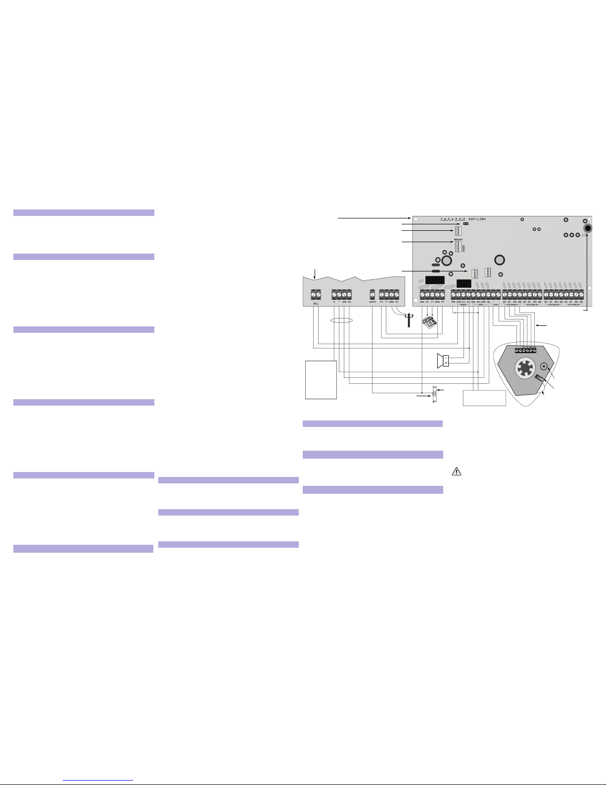
Figure 2
Partial View of EVO96
Control Panel
Listen-In Module
DGP-LSN4
Siren
from
external
phone line
if not using an
external power
supply for the
DGP-LSN4,
connect this to
the RED BUS
on the
DGP-LSN4.
External Power Supply
N.O.
switch
Memory Key
Reset Jumper
volume
control dial
anti-tamper
switch
Firmware Upgrade
Service Keypad
Ground
clamp
Cold water pipe
grounding
CAT-5 cable (4 twisted pair) Max
152m (500ft)
Use one pair for the SP
connections another for the MK
connections, and two pairs for
the AUX connections.
Listen-In
Substation #1
DGP-SUB1
buzzer
Background Music Input
 Loading...