

Page 1
INSTALLATION GUIDE OF DG-85 FOUR-ELEMENT
INTELLIGENT PIR INTRUSION DETECTOR
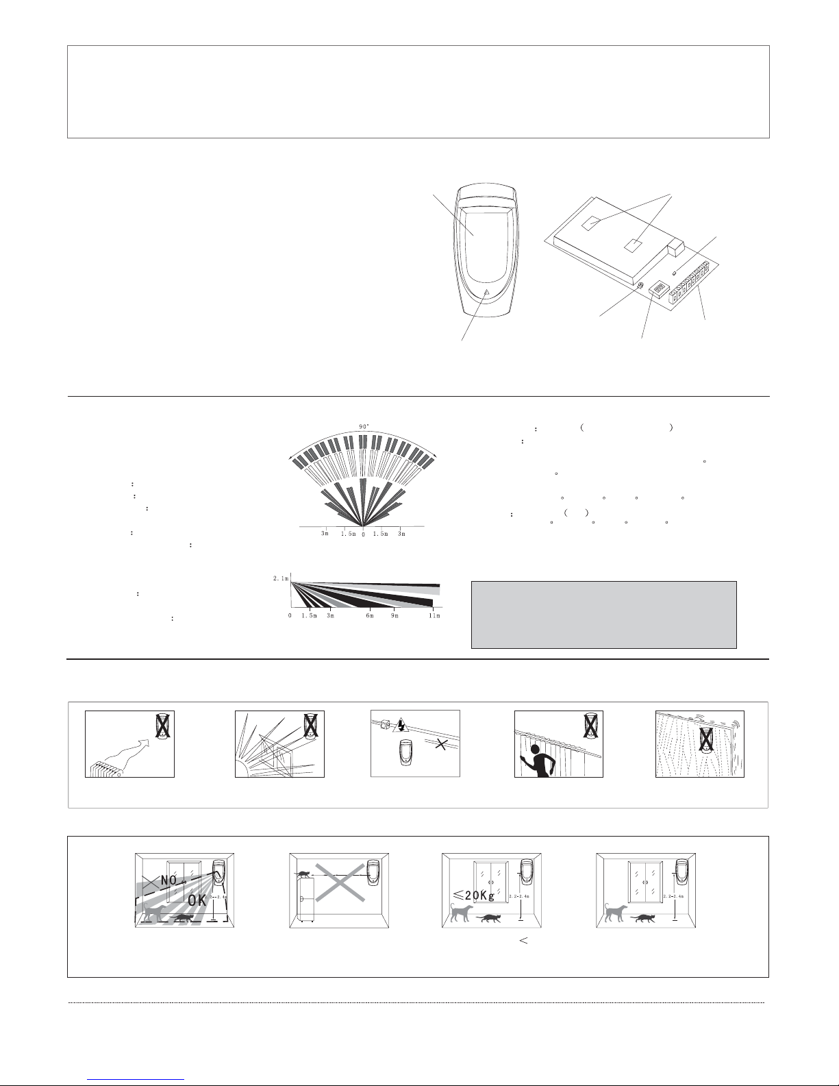
Lens
Walk-test LED
PIR
LED
Code switch
Sensitivity adjust
Figure 1.General View Figure 2.Inside View
2.Specifications
Top view
Side view
Connect terminals
Models:
Input Voltage 9-16VDC
Cyrrent Drain 30mA@ 12VDC
Detection Range 11.6m*11.6m
Alarm output NC.>100mA/28VDC
Anti white light resistance
>20000LUX
Installation height:2m-2.7m
Tamper switch NC.100mA/28VDC
DG-85
DG-85DMF
DG-85DMT
PIR Section:Lens Date
NO.of Curtain Beams (11+11+9)*2=62
Tripping Indication:
lndicator lights for about 10-30 seconds
Anti -EMI/RFI 10V/m 10MHz-1000MHz
Motion test 0.2m/s-3.5m/s(0.6ft-11ft)
Humidity 5%-95% RH
Accessories:
BR-1:Surface mounted swivel bracket,adjustable 30
down and 45 left/right.
Environmental:
Operating Temp: -10 C to50 C(14 F to 122 F )
Storage Temp :-20 C to 60 C (-4 F to 40 F)
Physical
Size(H*W*D):176*85*69mm
3.Installation
3.1 General Guidelines
No directfacing cold
/hot source
No directsun shine Keep awayfrom high
pressure power
No facingmetal wall Installation base
should bestable
1.Brief Introduction
DG-85 is a kind of PIR intrusion detector integrating the most
advanced security technology. It adopts 2 dual PIR sensors with
high accuracy,intelligent digi-tal chip, advanced ,<True Motion
Recognition & Anti-pests>of tware technology, which can help
it to make an accurate judgment of trueintruder or other interfer
-ence that can cause wrong alarm.And it is with function of auto
-matic memory of environmental change, which can avoid wro
-ng alarm a used by hot & cold air, opera-tion machine interfere
-nce. It can prevent effectively the interference cause by a 25 kg
past or 10 cats, insect, mouse, birds etc. Its super filter can be
used indoor and outdoor. This has clear various interference
that com-mon PIR detector can't overcome; and put an end to
wrong alarm and miss alarm .DG-85 has two different working
modes: bus mode and relay mode, can be used for all kinds of
control panels on the market.
This deviceis coherent toEurope parliament direct1999/5/EC
necessary itemsand rules, andalso coherent tothe main spirits
of radioand telecom terminal equipments on March 9 . 1999.
The devicealso reaches theCanadian standard RSS-210. It can
be usedindoor and outdoor, whichcan reach its maximum protection andavoidance of aboveinterference.
th
3.2Anti-pests installation
Theupperpartofthe
detection area is non
anti-pests area
Never face the detector to
the place that pests can
climb up directly
20KgAnti-pests weight The installation height
of the detector is 2.2-2.4
meters canAnti-pests
Page 2
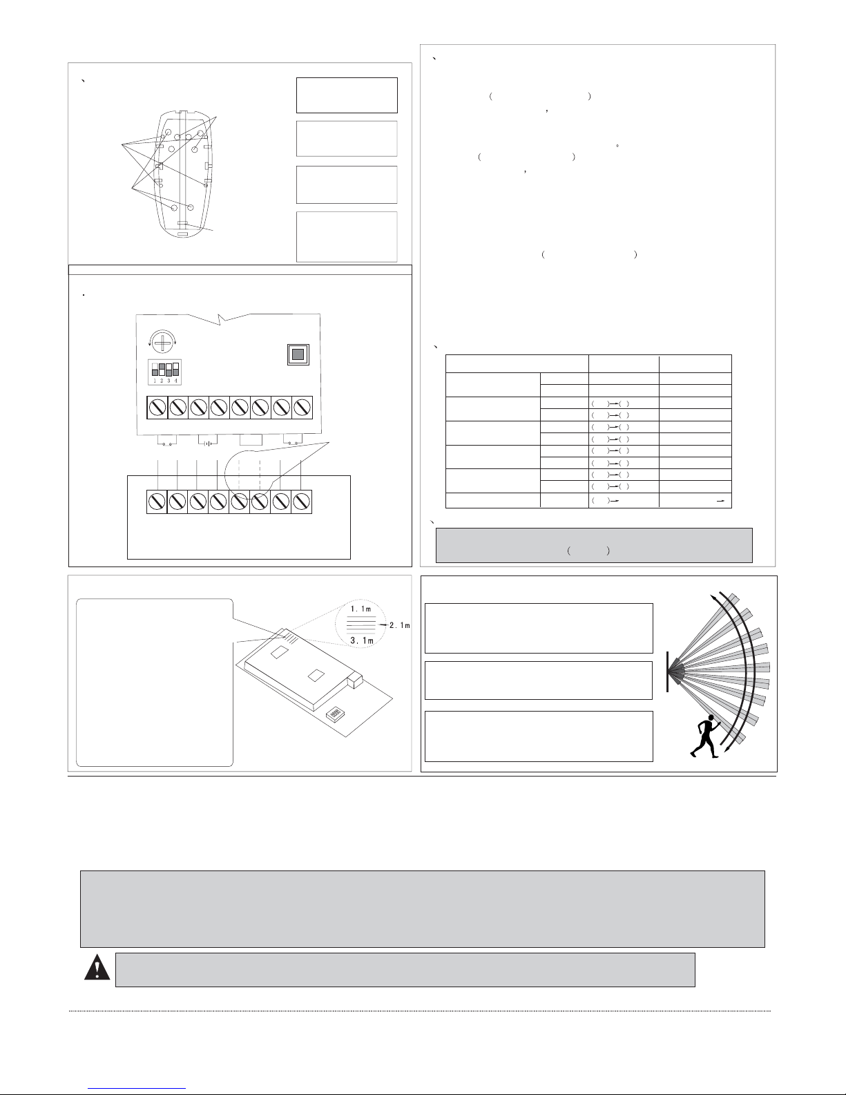
Wall mounting
holes
Cable hole
Bracket mounting
holes
3.3Illustrated Installation Procedure
1 Open holes on base:
A.Mask the drilling
porints and drill in the
the wall.
B.Route the cables
into the base via the
rear channel.
C.Insert two nails and
arrach the base to the
wall with two screws.
D.Insert the bottom
edge of the large PCB
under this tab&press
the top edge in.
3 function of coding switch:
Corner mounting
holes
DG-85 has two different working modes:bus mode and relay mode,the mode choosing
can be conducted by DIP switch.
4 Setting of coding switch:
theswitch1ofDIP=OFF
When setting to the relay mode DG-85 transmits alarm and temper signal by relay as stan-
dard sensors, same as the figure, can be powered by contacted the power of paneland the
"RED","BLK" of the sensor,"GRN","YEL" unused, on relay mode, the setting only can
be amended by DIP switch and trim pot-ntiometer
Relay mode
Bus mode theswitch1ofDIP=ON
When setting to bus mode DG-85 transmits alarm, tamper signals and datas by bus,and setting the sensoras well. On bus mode, DG-85 can be directly connected with control panel. sameas thefigure, can be pow-red by contacted the power of panel and the "RED","BLK" of
the sens-r,"GRN","YEL" connected with the correspondanceterminals. Onbus m-de,the setting can be amended by DIP switch and trim potentiometer, also can by system keypad(should be compated with system)get into programming mode.
Single or dual edge processing
This setting direct the DSP digital signal process working mode.Single side mode
is used the normal situation few of interference. Both sides process(out/in analysis)
mode can effectively reduce fault alarm. So, we recommend use this working mode
when the sensor in stallated near interfere resource.
LED setting
LED light 5 second when detected the energy of the moving signal can result alarm enough,
when the energy of the signal not enough, LED blink.
NC
COM
Tamper
Alarm output
Power
DG-85 PCB
RED BLK
GRN
YEL TMP TMP
Communicate
bus
GRN
AUX+
AUX-
YEL
ZONE
24H/ZONE
When relaymode,
these twowires not
connect
5 Sensitivity adjustment:
The trim potentiometer will turn bigger when turn clockwise, reverse result
when turn counter-colockwise 0.25s-2s
7. Motion test to protected area
The best operation height of DG85 is 2.1 meter, a little higher or
loweris also permitted. Confi
-rm the adjustableheight marko
-ntheright upside on cover tally
with the installation height.
If another installationheight is
needed, re-adjust the PCB in acc
-ordance with your needs. Mot
-ion test is necessarily required
inthe protection area in order
to confirm that areas need pro
-tection are within the prote-
ctive area.
6. PCB height setting
A. Install the cover, close the fastening position.
Guarantee that the front and back cover close
Tightly without any space or the looseness of
anti-water cover can't prevent humidity entering
into the parts.
B. Crossing to any direction of the detection area,
your walking will cause the LE D indicator to
light for 2-3 seconds (refer to the right diagram)
C. Perform motion test from contrary directions
in order to confirm the boundary of two sides.
Make confirmed thatdetection center pointing to
the center of protected area.
Contral panel
2 Wire up the terminal block
Function
Bus mode
Relay mode
Work mode
Digital signal process
LED
Tamper confirm
Invalid
Valid
Invalid
Valid
Invalid
Valid
Single side
Both sides
Relay
Bus
Unused
Unused
DIP switch1=OFF
DIP switch1=ON
DIP switch2=OFF
DIP switch2=ON
DIP switch3=ON
DIP switch3=OFF
Unused
Unused
Unused
Unused
001 1 =OFF
001 1 =ON
001 2 =OFF
001 2 =ON
001 3 =OFF
001 3 =ON
001 5 =ON
001 5 =OFF
002 001=010
Trim potentiometer 0 10
Sensitivity
Moving signal instruct
Even the most sophisticated detcetors can sometimes be defeated or may fail to warn due to :DC power failure/improper connection, malicious masking of the lens,tampering with the optical system, decreased sensitivity in ambient temperatures near that of the human body and unexpected failure of a component part.The above list includes the most common reasons for failure recommended that the detector and the entire alarm system bechecked weekly, toensure proper performance.An alarm system should not beregarded asa substitute for insurance. Home & property owners or renters shouldbe prudent enough to continue insuringtheir lives & property, even though they are protected by analarm system.
WARNING! Changes or modifications to this unit not expressly approved by the party responsible for compliance could
void the user s authority to operate the equipment.
This devicehas been tested and found to comply with the limits for a Class B digitaldevice, pursuant harmful interference in residential installations .This equipment
generates,uses andcan radiate radio frequency energy and ,if not installed andused inaccordance with theins-tructions ,may cause harmful in-terference toradio and television reception.However, there is noguarantee that interference will not occur in aparticu lar installation .If this device does cause such interference , which can be verfied by turning the device off and on ,the user isencouraged to eliminatethe interference by one or more of the followingmeasures:
- Increasethe distance betweenthe device andthe receiver.
- Connectthe device toan outlet ona circuit different from the onethat supplies power to the receiver.
4.Special comments
P/N 20605002A00
 Loading...