

Page 1
SYSTEM PROGRAMMING GUIDE
Software Versions 3.1 (728+, 738EX+ and 738+), 3.2 (728EX4+, 728DZ8+ and 748+) and 3.3 (728EX+)
INSTALLER CODE
Full access to programming, except user access codes (PINs). No access to arming/disarming. Use only numeric keys from [1] to [10] (key
[10] = 0). For default installer codes, refer to Table 1 below.
Table 1:
728EX+ = 727272 728EX4+ = 727272 738EX+ = 737373 748+ = 484848
728+ = 282828 728DZ8+ = 282828 738+ = 383838
KEYPAD TROUBLE DISPLAY
Press the [TBL]/[TRBL] key to view the trouble. Refer to Table 2 below.
[1]
- No Battery or Low Voltage
[2]
- Power Failure
[4]
- Bell Output Disconnected [9] - Tamper or Zone Wiring Failure
[5]
- Maximum Bell Current [10] - Telephone Line Monitoring Failure
[6]
- Maximum Auxiliary Current [11] - Fire Loop Trouble
Default Installer Codes by Control Panel
Ta ble 2:
Trouble Display
[7]
- Communicator Report Failure
[8]
- Timer Loss*
* To clear the Timer Loss trouble, refer to Key Access Programming on page 12 (the [
Press the [
CLEAR] button to clear troubles.
MEM] key).
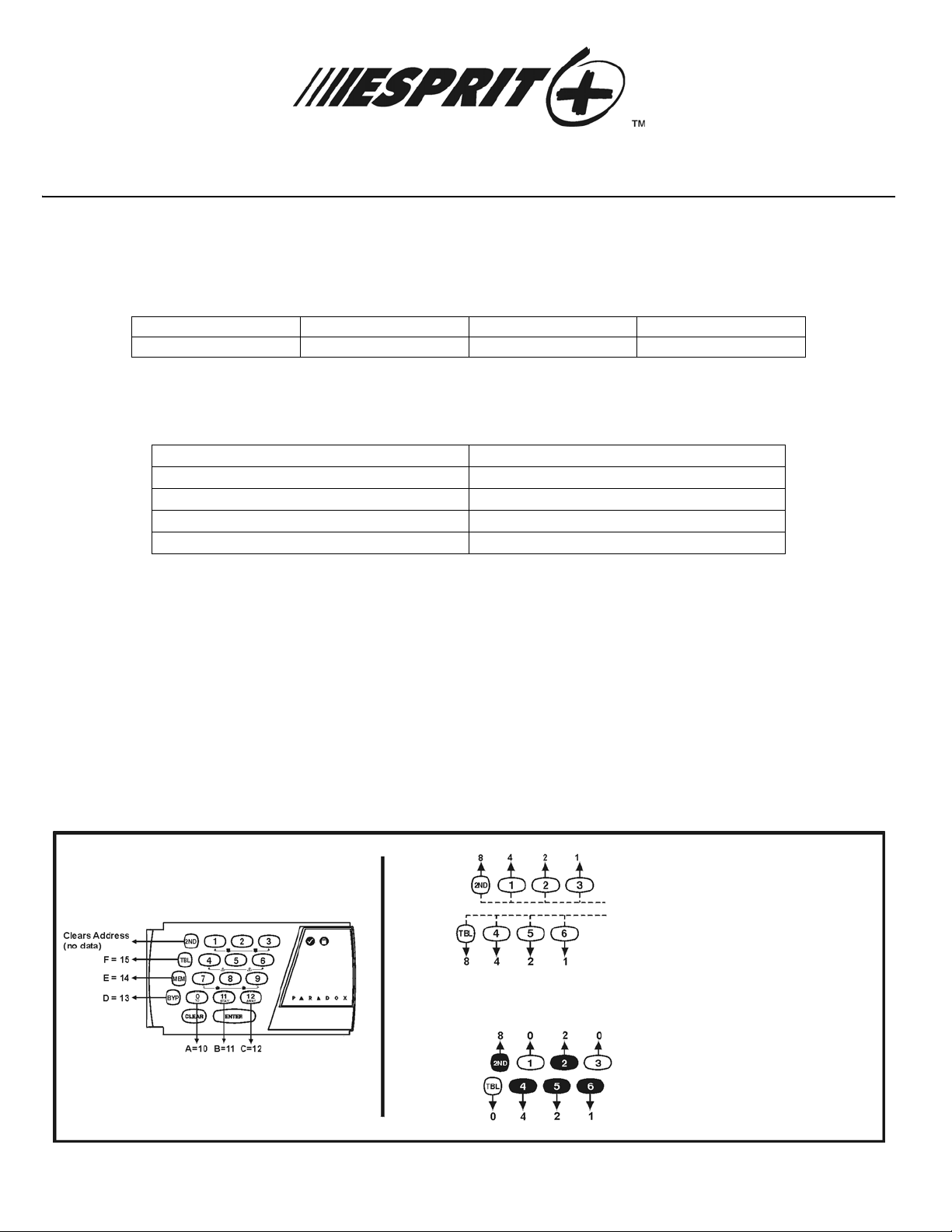
HEXA PROGRAMMING
Addresses 000 to 043 and 300 to 527 are programmed using the Hexa Programming method. In this mode, you can enter any hexadecimal
digit from 0 - F where keys [1] to [9] represent digits 1 to 9 respectively; the other keys represe nt hexadecimal digits A to F as shown in
Figure 1 on page 1. To program using the Hexa Programming method:
1) Press [
2) The [
3) Enter the desired 3-digit [
4) The keypad will display the 2-digit data currently saved at this address as described in Figure 1 on page 1
5) Enter 2-digit [
6) Return to step 2 or press [
ENTER] + [INSTALLER CODE] (default: see Table 1 on page 1)
ENTER] key will flash indicating you are in programming mode
ADDRESS]
DATA] and do not press [ENTER], the software automatically saves the data
CLEAR] to exit programming mode
Figure 1: Hexa Digit Data Display For LED Keypads
Note: LCD keypads will display current data on the screen.
Each key in the first 2 rows of the keypad represents a specific value when the key is lit, as shown above. If the key
isn’t lit, the key represents 0. The sum of the values of the lit keys in the first row correspond to the second hexa
digit. The sum of the values of the lit keys in the second row correspond to the first hexa digit as shown in the
example below.
If the key is not lit, value = 0
Sum of the first row = second hexa digit
Sum of the second row = first hexa digit
Note: Values 10 to 15 represent hexa digits A to F respectively. See keypad to the left.
Esprit+ - 1 - Programming Guide
= Second digit = 8 + 2 = 10
= First digit = 4 + 2 + 1 = 7
Therefore 2-digit data = 7A
Page 2

STREAMLINED SECTION PROGRAMMING
This is an alternate method to Hexa Programmi ng. The addresses (000 - 043 and 300 - 527) programmed in the Hexa Programming
method are grouped into 67 sections where each section co ntains four addresses (i.e. section 00 = addresses 000 - 003). Using this
method allows you to program 8 digits (4 addresses) without having to exit and reenter addresses.
Note, the keypad will not display the current data in the Hexa Streamlined Programming method.
To program using the Hexa Streamlined Section method:
1) Press [
2) The [
3) Enter 2-digit [
4) The [
5) Enter 8-digit [
ENTER] + [INSTALLER CODE] (default: see Table 1 on page 1) + [7]
ENTER] and [2ND] keys will flash to indicate you are in programming mode
SECTION] (00 - 67)
ENTER] key will remain on while the [2ND] key will be off
DATA] to program the section
6) The keypad will "beep" to indicate that the section has been programmed, data is saved and the software has advanced to the next
section
7) Return to step 4 or press [
CLEAR] to exit programming mode
ZONE RECOGNITION
Device
connected to
which input?
728+
728EX+
728EX4+**
728+
728DZ8+**
738EX+
738+
738+
748+
748+
728DZ8+**
No A TZ
With ATZ
No ATZ
No A TZ
With ATZ
No ATZ
With ATZ
Control Panel
Input 1 = Zone 1 Zones 1 & 2 Zone 1 Zone 1 Zones 1 & 7 Zone 1 Zones 1 & 13*
Input 2 = Zone 2 Zones 3 & 4 Zone 2 Zone 2 Zones 2 & 8 Zone 2 Zones 2 & 14*
Input 3 = Zone 3 Zones 5 & 6 Zone 3 Zone 3 Zones 3 & 9 Zone 3 Zones 3 & 15
Input 4 = Zone 4 Zones 7 & 8 Zone 4 Zone 4 Zones 4 & 10 Zone 4 Zones 4 & 16
Input 5 = N/A N/A Zone 5 Zone 5 Zones 5 & 11 Zone 5 Zones 5 & 17
Input 6 = N/A N/A Zone 6 Zone 6 Zones 6 & 12 Zone 6 Zones 6 & 18
Input 7 = N/A N/A Zone 7 N/A N/A Zone 7 Zones 7 & 19
Input 8 = N/A N/A N/A N/A N/A Zone 8 Zones 8 & 20
Input 9 = N/A N/A N/A N/A N/A Zone 9 Zones 9 & 21
Input 10 = N/A N/A N/A N/A N/A Zone 10 Zones 10 & 22
Input 11 = N/A N/A N/A N/A N/A Zone 11 Zones 11 & 23
Input 12 = N/A N/A N/A N/A N/A Zone 12 Zones 12 & 24
Keypad
Zone 1 = Zo n e 5** Zone 9** Zone 9 Zone 7 Zone 13 Zone 13 Zone 13*
Zone 2 = Zo n e 6** Zone 10** Zone 8 Zone 8 Zone 14 Zone 14 Zone 14*
* Control panel does not distinguish between zones 13 and 14 and keypad zones 1 (zone 13) and 2 (zone 14).
** The 728EX4+ and 728DZ8+ control panels do not support any keypad zone s.
WARNING: This equipment must be installed and maintained by qualified service personnel only.
Esprit+ - 2 - Programming Guide
Page 3

INSTALLER / PANEL ANSWER OPTIONS
Streamline Section Data
___ / ___ Installer code (1st, 2nd digit) 000
___ / ___ Installer code (3rd, 4th digit) 001
00
Streamline Section Data
01
___ / ___ Installer code (5th, 6th digit) 002
___ / ___ Panel answer opti ons
___ / ___ Panel Identifier (1st, 2nd digit) 004
___ / ___ Panel Identifier (3rd, 4th digit)
___ / ___ PC Password (1st, 2nd digit) 006
___ / ___ PC Password (3rd, 4th digit)
Description
Number of rings (Max. 15)
Description
Address Answering Machine Override
[2ND] or [1] = disabled [5] = 40 seconds
[2] = 16 seconds [6] = 48 seconds
[3] = 24 seconds [7] = 56 seconds
003
Address
005
007
[4] = 32 seconds [8] to [F] = 60 seconds
First digit disables “Answering Machine Override”
ND] or key [1]), or determines period of time
(key [2
between first and second call (see above). Second
digit determines number of rings required before
panel will answer. If [2
not answer (default value is [2
Identifies the control panel to the PC.
{
Identifies the PC to the panel.
{
ND][2ND] is entered, panel will
ND] [8]).
TELEPHONE AND ACCOUNT NUMBERS
If only one central station phone number is used, program the same number for telephone number 1 and 2. If on ly one account num be r is
required, the same number must be entered for both account "A" and "B".
[10] = the number "0" [
[11] = * [
[12] = # [
BYP] = switch from pulse to tone while dialing
MEM] = pause 4 seconds
TRBL] = end of number
Computer Telephone Number
Streamline Section Streamline Section
02
Central Station Telephone Number 1
Streamline Section Streamline Section
04
Central Station Telephone Number 2
Streamline Section Streamline Section
06
Account “A” and “B” (View at addresses 032 to 035)
Streamline Section
08
(View at addresses
__/__/__/__/__/__/__/__
1 2 3 4 5 6 7 8 9 10 11 12 13 14 15 16
(View at addresses
__/__/__/__/__/__/__/__
1 2 3 4 5 6 7 8 9 10 11 12 13 14 15 16
(View at addresses
__/__/__/__/__/__/__/__
1 2 3 4 5 6 7 8 9 10 11 12 13 14 15 16
__/__/__/__ __/__/__/__
1234 5678
AB
008
to
015
016
024
)
to
to
03
023
05
031
07
)
)
__/__/__/__/__/__/__/__
__/__/__/__/__/__/__/__
__/__/__/__/__/__/__/__
Press the [TRBL] key to
end phone number if
less than 16 digits are
programmed.
Press the [TRBL] key to
end phone number if
less than 16 digits are
programmed.
Press the [TRBL] key to
end phone number if
less than 16 digits are
programmed.
For 3 digit account
numbers, enter “skip”
([2
ND]) as first digit.
Esprit+ - 3 - Programming Guide
Page 4
Streamline Section Data
[2
ND] / [2ND] Future Use 036
[2ND] / ___ 1st digit: Value must be entered
09
___ / ___ 1st digit: Communicator Format 1
___ / ___ 1st digit: PGM1 type
Streamline Section Data
Description
ND])
(i.e. [2
2nd digit: Time correction (see
table at right)
2nd digit: Communicator Format 2
2nd digit: PGM2 type
Description
Address
Address Time Correction Table
[8] = Minus 4 seconds
[9] = Minus 8 seconds
[10] = Minus 12 seconds
[11] = Minus 16 seconds
[12] = Minus 20 seconds
[
BYP
[
MEM
[
TRBL
037
038
[2ND] = No adjustment
[1] = Plus 4 seconds
[2] = Plus 8 seconds
[3] = Plus 12 seconds
[4] = Plus 16 seconds
[5] = Plus 20 seconds
[6] = Plus 24 seconds
[7] = Plus 28 seconds
039
___ / ___ PGM1 040
___ / ___ PGM2 041
10
___ / ___ PGM Mask 1 042
___ / ___ PGM Mask 2
043
Communicator Formats
Key Key * = 4-digit account codes only
[2
ND] = ADEMCO slow (1400Hz, 1900Hz, 10bps) [6] = RADIONICS with PARITY (1400Hz, 40bps)
[1] = (1400Hz, 1800Hz, 10bps) [7] = RADIONICS with PARITY (2300Hz, 40bps)
[2] = SILENT KNIGHT fast (1400Hz, 1900Hz, 20bps) [8] = * ADEMCO express
[3] = SESCOA (2300Hz, 1800Hz, 20bps) [9] = * ADEMCO contact ID (programmable codes)
[4] = RADIONICS (40bps with 1400Hz handshake) [10] = * ADEMCO contact ID (all codes)
[5] = RADIONICS (40bps with 2300Hz handshake) [
TRBL] = * DTMF - no handshake (personal dialing)
]
= Minus 24 seconds
]
= Minus 28 seconds
]
= Minus 32 seconds
Programmable Contact ID Event Codes
All addresses from 300 to 527 (sections 11 to 67) programmed with values other than [2ND] [2ND] will report the contact ID codes corresponding to the
values programmed. Values to be programmed should be selected from this table.
CID Reporting Code Prog. Value CID Reporting Code Prog. Value
100: A
110: F
111: F
112: C
113: W
114: H
115: P
116: D
117: F
118: N
120: P
121: D
122: S
123: A
130: B
131: P
132: I
133: 24H
136: B
137: B
138: B
140: G
150: 24 H
151: G
152: R
153: L
154: W
155: F
156: D
157: L
158: H
159: L
161: L
UXILIARY ALARM [2ND] / [1] 300: SYSTEM TROUBLE [2] / [2]
IRE ALARM [2ND] / [2] 301: AC LOSS [2] / [3]
IRE SMOKE [2ND] / [3] 302: LOW SYSTEM BATTERY [2] / [4]
OMBUSTION [2ND] / [4] 305: SYSTEM RESET [2] / [5]
ATER FLOW [2ND] / [5] 306: PROGRAM CHANGED [2] / [6]
EAT [2ND] / [6] 309: BATTERY TEST FAIL [2] / [7]
ULLSTATION [2ND] / [7] 320: SOUNDER/RELAY TROUBLE [2] / [8]
UCT [2ND] / [8] 321: BELL 1 TROUBLE [2] / [9]
LAME [2ND] / [9] 323: ALARM RELAY TROUBLE [2] / [10]
EAR ALARM [2ND] / [10] 350: COMMUNICATION TROUBLE [2] / [11]
ANIC ALARM [2ND] / [11] 351: TELCO 1 FAULT [2] / [12]
URESS [2ND] / [12] 354: FAIL TO COMMUNICATE [2] / [BYP]
ILENT PANIC [2ND] / [BYP] 370: PROTECTION LOOP TROUBLE [2] / [MEM]
UDIBLE PANIC [2ND] / [MEM] 371:
URGLARY [2ND] / [TRBL] 372: PROTECTION LOOP SHORT [3] / [2ND]
ERIMETER BURGLARY [1] / [2ND] 373: FIRE LOOP TROUBLE [3] / [1]
NTERIOR BURGLARY [1] / [1] 382: SENSOR TROUBLE [3] / [2]
R BURGLARY [1] / [2] 383: SENSOR TAMPER [3] / [3]
URGLARY OUTDOOR [1] / [3] 400: OPEN / CLOSE [3] / [4]
URGLARY TAMPER [1] / [4] 401: OPEN / CLOSE BY USER # [3] / [5]
URGLARY NEAR ALARM [1] / [5] 402: GROUP OPEN / CLOSE [3] / [6]
ENERAL ALARM [1] / [6] 403: AUTOMATIC OPENING / CLOSING [3] / [7]
OUR AUXILIARY [1] / [7] 404: LATE TO OPEN / CLOSE [3] / [8]
AS DETECTED [1] / [8] 407: REMOTE ARM DOWNLOAD [3] / [9]
EFRIGERATION [1] / [9] 410: REMOTE ACCESS [3] / [10]
OSS OF HEAT [1] / [10] 441: OPEN / CLOSE - STAY MODE [3] / [11]
ATER LEAKAGE [1] / [11] 570: BYPASS [3] / [12]
OIL BREAK ALARM [1] / [12] 572: 24 HOUR ZONE BYPASS [3] / [BYP]
AY TROUBLE ALARM [1] / [BYP] 573: BURGLARY BYPASS # [3] / [MEM]
OW GAS LEVEL [1] / [MEM] 574: GROUP BYPASS [3] / [TRBL]
IGH TEMPERATURE [1] / [TRBL] 601: MANUAL TEST [4] / [2ND]
OW TEMPERATURE [2] / [2ND] 602: PERIODIC TEST [4] / [1]
OSS AIR FLOW [2] / [1] 625: TIME / DATE RESET [4] / [2]
P
ROTECTION LOOP OPEN
[2] / [TRBL]
Esprit+ - 4 - Programming Guide
Page 5

REPORTING CODES
All digits from [1] to [F] are valid. [2ND] = digit will not be reported except for Contact ID programmable codes. For single digi t reporting,
enter “skip” ([2
If the Contact ID Format (all codes) is selected, addresses 300 to 527 (sections 11 to 67) do not have to be programmed
(select Contact ID (all codes) - key [10] for both central station numbers at section 09 - address 038 on page 4).
ARMING (CLOSING) REPORT CODES:
Streamline
Section
11 17
12 18
13 19
14 20
ND]) as the first digit (default = [2ND] / [2ND]).
Data Description Address
___ / ___ Auto / Espload 300 ___ / ___ User Code 23 324
___ / ___ Master 301 ___ / ___ User Code 24 325
___ / ___ User Code 1 302 ___ / ___ User Code 25 326
___ / ___ User Code 2 303 ___ / ___ User Code 26 327
___ / ___ User Code 3 304 ___ / ___ User Code 27 328
___ / ___ User Code 4 305 ___ / ___ User Code 28 329
___ / ___ User Code 5 306 ___ / ___ User Code 29 330
___ / ___ User Code 6 307 ___ / ___ User Code 30 331
___ / ___ User Code 7 308 ___ / ___ User Code 31 332
___ / ___ User Code 8 309 ___ / ___ User Code 32 333
___ / ___ User Code 9 310 ___ / ___ User Code 33 334
___ / ___ User Code 10 311 ___ / ___ User Code 34 335
___ / ___ User Code 11 312 ___ / ___ User Code 35 336
___ / ___ User Code 12 313 ___ / ___ User Code 36 337
___ / ___ User Code 13 314 ___ / ___ User Code 37 338
___ / ___ User Code 14 315 ___ / ___ User Code 38 339
Streamline
Section
Data Description Address
___ / ___ User Code 15 316 ___ / ___ User Code 39 340
___ / ___ User Code 16 317 ___ / ___ User Code 40 341
15 21
16 22
___ / ___ User Code 17 318 ___ / ___ User Code 41 342
___ / ___ User Code 18 319 ___ / ___ User Code 42 343
___ / ___ User Code 19 320 ___ / ___ User Code 43 344
___ / ___ User Code 20 321 ___ / ___ User Code 44 345
___ / ___ User Code 21 322 ___ / ___ User Code 45 346
___ / ___ User Code 22 323
23
___ / ___ User Code 46 347
___ / ___ User Code 47 348
___ / ___ User Code 48 / 349
(Duress)
Continues on next page.
Esprit+ - 5 - Programming Guide
Page 6

DISARMING (OPENING) REPORT CODES (reset code “empty”)
Streamline
Section
23
24 30
25 31
26 32
27 33
Data Description Address
See previous page
___ / ___ Auto / Espload 350
___ / ___ Master
___ / ___ User Code 1 352 ___ / ___ User Code 25 376
___ / ___ User Code 2 353 ___ / ___ User Code 26 377
___ / ___ User Code 3 354 ___ / ___ User Code 27 378
___ / ___ User Code 4 355 ___ / ___ User Code 28 379
___ / ___ User Code 5 356 ___ / ___ User Code 29 380
___ / ___ User Code 6 357 ___ / ___ User Code 30 381
___ / ___ User Code 7 358 ___ / ___ User Code 31 382
___ / ___ User Code 8 359 ___ / ___ User Code 32 383
___ / ___ User Code 9 360 ___ / ___ User Code 33 384
___ / ___ User Code 10 361 ___ / ___ User Code 34 385
___ / ___ User Code 11 362 ___ / ___ User Code 35 386
___ / ___ User Code 12 363 ___ / ___ User Code 36 387
___ / ___ User Code 13 364 ___ / ___ User Code 37 388
___ / ___ User Code 14 365 ___ / ___ User Code 38 389
___ / ___ User Code 15 366 ___ / ___ User Code 39 390
___ / ___ User Code 16 367 ___ / ___ User Code 40 391
351
___ / ___ User Code 17 368 ___ / ___ User Code 41 392
___ / ___ User Code 18 369 ___ / ___ User Code 42 393
28 34
29 35
ALARM REPORT CODES FOR ZONES 1 TO 24 (see warning below):
Streamline
Section
36 39
37 40
38 41
___ / ___ User Code 19 370 ___ / ___ User Code 43 394
___ / ___ User Code 20 371 ___ / ___ User Code 44 395
___ / ___ User Code 21 372 ___ / ___ User Code 45 396
___ / ___ User Code 22 373 ___ / ___ User Code 46 397
___ / ___ User Code 23
___ / ___ User Code 24
Data Description Address
___ / ___ Zone 1 400 ___ / ___ Z one 13 412
___ / ___ Zone 2 401 ___ / ___ Z one 14 413
___ / ___ Zone 3
___ / ___ Zone 4 403 ___ / ___ Z one 16 415
___ / ___ Zone 5 404 ___ / ___ Zone 17 416
___ / ___ Zone 6 405 ___ / ___ Zone 18 417
___ / ___ Zone 7 406 ___ / ___ Zone 19 418
___ / ___ Zone 8 407 ___ / ___ Zone 20 419
___ / ___ Zone 9 408 ___ / ___ Zone 21 420
___ / ___ Zone 10 409 ___ / ___ Zone 22 421
___ / ___ Zone 11 410 ___ / ___ Zone 23 422
___ / ___ Zone 12 411 ___ / ___ Zone 24 423
(fire add. 100) 402 ___ / ___ Zone 15 414
374 ___ / ___ User Code 47 398
375
Streamline
Section
___ / ___ User Code 48 /
(Duress)
Data Description Address
399
For zone recognition, refer to “Zone Recognition” on page 2.
Esprit+ - 6 - Programming Guide
Page 7

ALARM RESTORE REPORT CODES FOR ZONES 1 TO 24 (see warning below):
Streamline
Section
42 45
43 46
44 47
For zone recognition, refer to “Zone Recognition” on page 2.
ZONES 1 TO 24 SHUTDOWN REPORT CODES (see warning below):
Streamline
Section
48 51
Data Description Address
___ / ___ Zone 1 424 ___ / ___ Z one 13 436
___ / ___ Zone 2 425 ___ / ___ Z one 14 437
___ / ___ Zone 3
___ / ___ Zone 4 427 ___ / ___ Z one 16 439
___ / ___ Zone 5 428 ___ / ___ Z one 17 440
___ / ___ Zone 6 429 ___ / ___ Z one 18 441
___ / ___ Zone 7 430 ___ / ___ Z one 19 442
___ / ___ Zone 8 431 ___ / ___ Z one 20 443
___ / ___ Zone 9 432 ___ / ___ Z one 21 444
___ / ___ Zone 10 433 ___ / ___ Zone 22 445
___ / ___ Zone 11 434 ___ / ___ Zone 23 446
___ / ___ Zone 12 435 ___ / ___ Zone 24 447
Data Description Address
___ / ___ Zone 1 448 ___ / ___ Z one 13 460
___ / ___ Zone 2 449 ___ / ___ Z one 14 461
___ / ___ Zone 3
___ / ___ Zone 4 451 ___ / ___ Z one 16 463
(fire add. 100) 426 ___ / ___ Zone 15 438
(fire add. 100) 450 ___ / ___ Zone 15 462
Streamline
Section
Streamline
Section
Data Description Address
Data Description Address
___ / ___ Zone 5 452 ___ / ___ Z one 17 464
___ / ___ Zone 6 453 ___ / ___ Z one 18 465
49 52
50 53
For zone recognition, refer to “Zone Recognition” on page 2.
TAMPERS 1 TO 12 REPORT CODES (see warning below):
Streamline
Section
54 56
55
___ / ___ Zone 7 454 ___ / ___ Z one 19 466
___ / ___ Zone 8 455 ___ / ___ Z one 20 467
___ / ___ Zone 9 456 ___ / ___ Z one 21 468
___ / ___ Zone 10 457 ___ / ___ Zone 22 469
___ / ___ Zone 11 458 ___ / ___ Zone 23 470
___ / ___ Zone 12 459 ___ / ___ Zone 24 471
Data Description Address
___ / ___ Tamper 1 472 ___ / ___ Tamper 9 480
___ / ___ Tamper 2 473 ___ / ___ Tamper 10 481
___ / ___ Tamper 3 474 ___ / ___ Tamper 11 482
___ / ___ Tamper 4 475 ___ / ___ Tamper 12 483
___ / ___ Tamper 5 476
___ / ___ Tamper 6 477
___ / ___ Tamper 7 478
___ / ___ Tamper 8 479
Streamline
Addresses 484 - 495 are reserved for future use
Section
Data Description Address
For zone recognition, refer to “Zone Recognition” on page 2.
Esprit+ - 7 - Programming Guide
Page 8

TROUBLE REPORT CODES:
Streamline
Section
60 61
TROUBLE RESTORE REPORT CODES:
Streamline
Section
62 63
SPECIAL REPORT CODES:
Streamline
Section
64 66
Data Description Address
___ / ___ Max. aux. current 496 ___ / ___ Fire loop trouble 500
___ / ___ Bell disconnect /
max. bell current
___ / ___ Battery disconnect /
low voltage
___ / ___ Power failure
Data Description Address
___ / ___ Max. aux. current 504 ___ / ___ Fire loop trouble 508
___ / ___ Bell disconnect /
max. bell current
___ / ___ Battery disconnect /
low voltage
___ / ___ Power failure
Data Description Address
___ / ___ Test report 512 ___ / ___ Duress 520
___ / ___ Panic 1 513
___ / ___ Panic 2 514
___ / ___ Panic 3 515
497
498
499
505
506
507
Streamline
Streamline
Streamline
Section
Section
Section
Data Description Address
___ / ___ Timer loss
[2ND]/[2ND] Future Use
[2ND]/[2ND] Future Use
Data Description Address
___ / ___ Timer
programmed
___ / ___ Tamper / wiring fault
___ / ___ TLM restore
Data Description Address
[2ND]/[2ND] Future Use 521
[2ND]/[2ND] Future Use 522
[2ND]/[2ND] Future Use 523
501
502
503
509
510
511
Streamline
Section
65 67
Data Description Address
___ / ___ Late to close 516 ___ / ___ Login (Espload) 524
___ / ___ No movement 517 ___ / ___ Program Change 525
___ / ___ Partial Arming 518
___ / ___ Recent Close 519
[2ND]/[2ND] Future Use 526
[2ND]/[2ND] Future Use 527
Esprit+ - 8 - Programming Guide
Page 9

DECIMAL PROGRAMMING
1) Press [ENTER] + [INSTALLER CODE] (default: see Table 1 on page 1)
2) The [
3) Enter 3-digit [
4) The keypad will now display the current 3-digit data currently saved at this address as described in Figure 2 on page 9.
5) Enter 3-digit [
6) Return to step 2 or press [
ENTER] key will flash to indicate you are in programming mode
ADDRESS] (044 - 061)
DATA] (000 - 255) value and do not press [ENTER], the software will automatically save the data
CLEAR] to exit programming mode
Address Data
Description Default
044 ___ / ___ / ___ (hours) Auto arm time (between "000" and "023")
045 ___ / ___ / ___ (minutes) Auto arm time (between "000" and "059")
046 ___ / ___ / ___ (days) Auto test report every ? days (between "001" and "255") (000 = disabled)
047 ___ / ___ / ___ (hours) Auto test report (between "000" and "023")
048 ___ / ___ / ___ (minutes) Auto test report (between "000" and "059")
049 ___ / ___ / ___ (seconds) Exit delay 60 seconds
050 ___ / ___ / ___ (seconds) Entry delay 1 45 seconds
051 ___ / ___ / ___ (seconds) Entry delay 2 45 seconds
052 ___ / ___ / ___ (minutes) Bell cut-off time 5 minutes
053 ___ / ___ / ___ (x 15 mSec.) Zone speed 600 mSec.
054 ___ / ___ / ___ (minutes) Power failure report delay (000 = disabled) 30 minutes
055 ___ / ___ / ___ (x 15 minutes) "No movement" report time (000 = disabled) Disabled
056 ___ / ___ / ___ PGM timer setting (001 to 127 for seconds and 129 to 255 for minutes)
5 seconds
Add 128 to desired value in minutes (i.e. for 5 minutes: enter 5 + 128 = 133)
057 ___ / ___ / ___ Intellizone delay (in seconds, minimum = 10 seconds) 48 seconds
058 ___ / ___ / ___ Installer code lock (147 = locked, 000 = unlocked).
Esprit 728EX+ only: The BATT LED will flash and the dialer relay will open and close,
thus making a clicking noise, for 4 seconds during power up when Installer Lock is
enabled on the control panel.
059 ___ / ___ / ___ (seconds) Programmable delay before alarm transmission (005 to 063 seconds)
(000 = disabled)
060 ___ / ___ / ___ (seconds) Recent closing delay (000 = disabled )
061 ___ / ___ / ___ Future Use
Figure 2: Decimal Display For LED Keypads
Esprit+ - 9 - Programming Guide
Page 10

FEATURE SELECT PROGRAMMING
Addresses 062 to 126 are programmed using the Feature Select Programming method. In this method, every key on the keypad in each
address represents an option or feature. Pressing a key will display it on the keypad and pressing it again will extinguish the key. The ON or
OFF status of each key determines the selected feature. Addresses 080 to 085 are reserved for future use. To program using the Feature
Select Programming method:
1) Press [ENTER] + [INSTALLER CODE] (default: see Table 1 on page 1)
2) The [
3) Enter 3-digit [
4) After entering the address, the keypad will display the feature selection status. Turn the keys ON or OFF by pressing the appropriate
5) Return to step 3 to continue programming or press [
ENTER] key will flash to indicate you are in programming mode
ADDRESS] (062 - 126)
key until the desired options are set. Press the [
been accepted. The [
ENTER] key will flash to indicate that the software is awaiting the next address entry.
ENTER] key to accept, there will be a confirmation "beep" indicating the options h ave
CLEAR] to exit programming mode
062:
064:
066:
068:
070:
072:
074:
076:
078:
KEY SELECT:
Table 3:
[1] [2] [3] [4] [5] [6] [7] [8] [9] [10] [11] [12] [BYP][MEM]
Code Priority For System “A” / STAY
User #: 1 2 3 4 5 6 7 8 9 10 11 12 13 14 15 16
NNNNNNNNNNNN N N N N
User #: 17 18 19 20 21 22 23 24 25 26 27 28 29 30 31 32
NNNNNNNNNNNN N N N N
User #: 33 34 35 36 37 38 39 40 41 42 43 44 45 46 47 48
NNNNNNNNNNNN N N N N
Table 4:
KEY SELECT:
User #: 1 2 3 4 5 6 7 8 9 10 11 12 13 14 15 16
[1] [2] [3] [4] [5] [6] [7] [8] [9] [10] [11] [12] [BYP][MEM]
Code Priority For System “B” / AWAY
NNNNNNNNNNNN N N N N
User #: 17 18 19 20 21 22 23 24 25 26 27 28 29 30 31 32
NNNNNNNNNNNN N N N N
User #: 33 34 35 36 37 38 39 40 41 42 43 44 45 46 47 48
NNNNNNNNNNNN N N N N
Table 5:
KEY SELECT:
User #: 1 2 3 4 5 6 7 8 9 10 11 12 13 14 15 16
[1] [2] [3] [4] [5] [6] [7] [8] [9] [10] [11] [12] [BYP][MEM]
Code Priority for Codes with Bypass Access
NNNNNNNNNNNN N N N N
User #: 17 18 19 20 21 22 23 24 25 26 27 28 29 30 31 32
NNNNNNNNNNNN N N N N
User #: 33 34 35 36 37 38 39 40 41 42 43 44 45 46 47 48
NNNNNNNNNNNN N N N N
[
TRBL
[
TRBL
[
TRBL
]
]
]
[2ND]
[2ND]
[2ND]
Esprit+ - 10 - Programming Guide
Page 11

086:
See “TLM” table at right
Keyswitch = regular arm
Keyswitch arming
Call back
Auto arm on time
Auto arm on no movement
Pulse dialing
Partitioning
Silent zone/panic generates a silent alarm
(1:2) Pulse Europe
See “Reporting Options” table at right
N/A
Bell squawk on arm/disarm
Auto zone shutdown
088:
Automatic event buffer transmission
Panic 1 (keys [1] and [3])
Panic 2 (keys [4] and [6])
Panic 3 (keys [7] and [9])
Panic 1 silent
Panic 2 silent
Panic 3 silent
Key [10] - regular arming
Key [11] - stay or system A arm
6 digit access codes
Tamper Recognition
Beep on exit delay
Report zone restore on bell cut-off
Zones with EOL (1k9)
Always report disarm
KEY
OFF / ON
[2ND]
N
N
N
N
N
N
N
N
N
N
N
N
N
N
N
N
[1]
[2]
[3]
[4]
[5]
[6]
[7]
[8]
[9]
[10]
[11]
[12]
[BYP]
[MEM]
[TRBL]
KEY
N
N
N
N
N
N
N
N
N
N
N
N
N
N
N
N
OFF / ON
[2ND]
N
N
N
N
N
N
N
N
N
N
N
N
N
N
N
N
[1]
[2]
[3]
[4]
[5]
[6]
[7]
[8]
[9]
[10]
[11]
[12]
[BYP]
[MEM]
[TRBL]
N
N
N
N
N
N
N
N
N
N
N
N
N
N
N
N
Stay arm / System A
Enabled
Enabled
Enabled
Enabled
Tone dialing (DTMF)
Enabled
generates only a report
(1:1.5) Pulse USA
N/A
Enabled
Enabled
Enabled
Enabled
Enabled
Enabled
Audible
Audible
Fire
Enabled
Enabled
4 digit access code
Enabled
On zone closure
No EOL
Only after alarm
Telephone Line Monitoring (TLM)
KEY
[2
ND][1]
OFF OFF - TLM disabled
OFF ON - TLM generates trouble only
ON OFF - generates an alarm if armed
ON ON - silent alarm becomes audible
(address 086, key [9] has to be OFF)
Reporting Options
KEY
[11] [12]
OFF OFF - Reporting disabled
OFF ON - Regular reporting
ON OFF - Split* reporting (Alarms & System)
ON ON - Double reporting
Report Dialing Sequence (tel. no.)
Regular: 1,2,1,2,1,2,1,2, fail to comm.
Split*: Alarms - 1,1,1,1,1,1,1,1, fail to comm
Double: 1,1,1,1,1,1,1 ,1 , fa il to comm
* On alarm, all reports are made to Tel. #1 until system is
disarmed. Once disarmed, system reports are made to
Tel. #2.
System Armed [10] [11] System Disarmed*
Alarm as per
individual zone
definitions
Always generate
trouble and
alarm, audible or
silent as per
individual zone
definitions
* Exception: for 24 hour zones, the tamper definition
will follow the audible/silent alarm definition of the 24
hour zone.
** Silent zones will generate a silent alarm.
System - 2,2,2,2,2,2,2,2, fail to comm
2,2,2,2,2,2,2,2, fail to comm
Tamper / Wire Fault Definitions
KEY
OFF OFF - Tamper supervision
OFF ON - No alarm, trouble
ON OFF - Silent alarm.
ON ON - Audible alarm.
disabled
code reported
Trouble & alarm
codes reported
Trouble & alarm
codes reported**
090:
Exclude power failure from trouble display
Zone (4, 9 or 15) enabled***
Auto arm = regular arm
N/A
N/A
N/A
No tamper bypass
N/A
Zone doubling (ATZ)****
Audible trouble warning
Duress
Keypad zone 1 supervision
Keypad zone 2 supervision
N/A
N/A
N/A
KEY
OFF / ON
N
N
N
N
N
N
N
N
N
N
N
N
N
N
N
N
[2ND]
[1]
[2]
[3]
[4]
[5]
[6]
[7]
[8]
[9]
[10]
[11]
[12]
[BYP]
[MEM]
[TRBL]
Enabled
N
Disabled***
N
Stay / System A
N
N/A
N
N/A
N
N/A
N
Tamper follows zone bypass definition
N
N/A
N
Enabled****
N
Enabled
N
Enabled
N
Enabled
N
Enabled
N
N/A
N
N/A
N
N/A
N
Esprit+ - 11 - Programming Guide
*** NOTE 1: This feature applies to the 728+, 728DZ8+, 738+
and 748+ only. When ATZ is enabled (address 090 key [8]
ON) and zone 3 is defined as a fire zone, this zone must be
disabled. If using a 728+ or 728DZ8+, zone 4 will be
disabled. If using a 738+, zone 9 will be disabled. If using a
748+, zone 15 will be disabled.
**** NOTE 2: This feature applies to the 728+, 728DZ8+,
738+ and 748+ only.
Page 12

Ta ble 6:
Zone Definition
KEY SELECT:
Intellizone = ON
Silent = ON
24Hr. / Fire = ON
Keypad zones cannot be set as 24Hr. zones. * When zone 3 is defined “24Hr.”, it becomes a fire zone
Instant = ON
Follow = ON
Delay 2 = ON
If ON, zone is armed on
Stay or “System A”
arming
If ON, zone is armed in
“System B” arming
Bypass enable = ON
[1] [2] [3] [4] [5] [6] [7] [8] [9] [10] [11] [12] [1] [2] [3] [4] [5] [6] [7] [8] [9] [10] [11] [12]
1 2 3 4 5 6 7 8 9 10 11 12 13141516171819202122 23 24
092:
NNNNNNNNNN N N
1 2 3 4 5 6 7 8 9 10 11 12 13141516171819202122 23 24
096:
NNNNNNNNNN N N
123* 4 5 6 7 8 9 10 11 12 13141516171819202122 23 24
100:
NNNNNNNNNN N N
1 2 3 4 5 6 7 8 9 10 11 12 13141516171819202122 23 24
104:
NNNNNNNNNN N N
1 2 3 4 5 6 7 8 9 10 11 12 13141516171819202122 23 24
108:
NNNNNNNNNN N N
123* 4 5 6 7 8 9 10 11 12 13141516171819202122 23 24
112:
NNNNNNNNNN N N
SYSTEM A / STAY SYSTEM A / STAY
123* 4 5 6 7 8 9 10 11 12 13141516171819202122 23 24
116:
NNNNNNNNNN N N
SYSTEM B SYSTEM B
123* 4 5 6 7 8 9 10 11 12 13141516171819202122 23 24
120:
NNNNNNNNNN N N
123* 4 5 6 7 8 9 10 11 12 13141516171819202122 23 24
124:
NNNNNNNNNN N N
094:
NNNNNNNNN N N N
098:
NNNNNNNNN N N N
102:
NNNNNNNNN N N N
106:
NNNNNNNNN N N N
110:
NNNNNNNNN N N N
114:
NNNNNNNNN N N N
118:
NNNNNNNNN N N N
122:
NNNNNNNNN N N N
126:
NNNNNNNNN N N N
Note: Do not use the Intellizone feature and an entry delay for the same zone, otherwise an alarm may occur as a user tries
to disarm the system.
Zones that are not selected at addresses 100 to 114 become “Delay 1” zones.
KEY ACCESS PROGRAMMING
Programs features quickly, without entering addresses or sections numbers. To activate Key Access Programming, press [ENTER] followed
by the the installer code, master code or user code 1 (code required depends on the desired feature; see below). Press the key
corresponding to the desired feature. Press [
programming mode.
Key Feature
[8]
[9]
[MEM]
[BYP]
[TRBL]
Installer Test Mode
In Installer Test mode, a confirmation beep (intermittent) indicates that the test
mode is enabled. A rejection beep indicates that the test mode is disabled. The
bell will squawk during walk testing to indicate opened, functional zones.
“Auto Arming” Time Program
Key [9] flashes. Enter 2-digit hour (00 to 23) and 2-digit minutes (00 to 59).
Panel Time Programming
[MEM] key flashes. Enter 2-digit hour (00 to 23) and 2-digit minutes (00 to 59).
Test Report
Reporting is enabled at address 086, keys [11] and [12] (see page 11). A value
must be entered at address 512 (page 8) and both telephone and account
numbers must be programmed.
Call Espload Via Telephone
Panel identifier and PC password (addresses 004 to 007 on page 3) and
computer telephone number (addresses 008 to 015 on page 3) must be
programmed.
ENTER] or [CLEAR] to exit. When communicating with Espload, it is impossible to enter
Codes that can access feature
Installer Code Only
Installer Code, Master Code or User Code 1
Installer Code, Master Code or User Code 1
Installer Code, Master Code or User Code 1
Installer Code, Master Code or User Code 1
[AWAY]
[STAY]
Answer Espload
This feature is available when using the ADP-1 adapter. In Espload, “blind dial”
must be activated in “modem setup” section and panel phone number
programmed (works also with ADP-1).
Cancel Communication Attempts
Until next reportable event.
Esprit+ - 12 - Programming Guide
Installer Code, Master Code or User Code 1
Master Code/User Code 1 only cancel calls to Espload
The Installer Code can cancel all communications
Page 13

CONNECTION DIAGRAMS
The system hardware will recognize the following zone conditions:
SINGLE ZONE CONNECTIONS
Figure 3: N.C. Contacts, without EOL Resistor Figure 4: N.C. Contacts, with EOL Resistor (UL/ULC)
Address 088,[MEM] = “ON” (EOL resistor disabled)
[10] = “OFF”
[11] = “OFF”
Address 090,[8] = “OFF” (ATZ disabled)
Tamper/Wire Fault disabled.
Address 088,[MEM] = “OFF” (EOL resistor enabled)
[10] = “OFF”
[11] = “OFF”
Address 090,[8] = “OFF” (ATZ disabled)
Tamper/Wire Fault disabled.
Figure 5: N.O. Contacts, with EOL Resistor (UL/ULC) Figu re 6: N.C. Contacts, without EOL Resistor, with Tamper
Recognition
Address 088,[MEM] = “OFF” (EOL resistor enabled)
Address 090,[8] = “OFF” (ATZ disabled)
[10] = “OFF”
[11] = “OFF”
Tamper/Wire Fault disabled.
Address 088,[MEM] = “ON” (EOL resistor disabled)
[10] = (See Tamper/Wire Fault definitions on
[11] = page 11.)
Address 090,[8] = “OFF” (ATZ disabled)
Figure 7: N.C. Contacts, with EOL resistor , with Tamper and Wire
Fault Recognition (UL/ULC)
Address 088,[MEM] = “OFF” (EOL resistor enabled)
[10] = (See Tamper/Wire Fault definitions on
[11] = page 11.)
Address 090,[8] = “OFF” (ATZ disabled)
Esprit+ - 13 - Programming Guide
Page 14

ADVANCED TECHNOLOGY ZONE CONNECTIONS (728+, 728DZ8+, 738+ AND 748+ ONLY)
Figure 8: N.C. Contacts, without EOL Resistor Figure 9: N.C. Contacts, without EOL Resistor, with Tamper
Recognition
Address 088,[MEM] = “ON” (EOL resistor disabled)
Address 090,[8] = “ON” (ATZ enabled)
[10] = “OFF”
[11] = “OFF”
Tamper/Wire Fault disabled.
Figure 10: N.O. Contacts, with EOL Resistor, with Tamper and
Wire Fault Recognition (UL/ULC)
Address 088,[MEM] = “OFF” (EOL resistor enabled)
Address 090,[8] = “ON” (ATZ enabled)
[10] = (See Tamper/Wire Fault defintions on
[11] = page 11.)
OTHER CONNECTION DIAGRAMS
Address 088,[MEM] = “ON” (EOL resistor disabled)
[10] = (See Tamper/Wire Fault defintions on
[11] = page 11.)
Address 090,[8] = “ON” (ATZ enabled)
Figure 11: Connecting One Keypad Zone Figure 12: Connecting Two Keypad Zones (639 only)
Esprit+ - 14 - Programming Guide
Page 15

Figure 13: Connecting Two Keypad Zones Using Two Keypads
:
Figure 14: Keypad Tamper Switch Connection Figure 15: PGM Output Relay Figure 16: Ground Start Circuit
Figure 17: Fire Alarm Zone Connections Figure 18: Fire Reset
It is recommended that all 4-wire smoke detectors be connected using a daisy chain configuration
Esprit+ - 15 - Programming Guide
Page 16

ESPRIT 728+ / 728EX+ / 728EX4+ / 728DZ8+ WIRING DIAGRAM
If using a 728+, please refer to
Inset 1 for the input terminals. For
the hardwired connections, refer
to Single Zone Connections on
page 13 and Advanced
T echnology Zone Connections on
page 14.
The maximium number of keypads per installation is
dependent on the auxiliary output, which is not to exceed
400mA. Refer to the Reference & Installation Manual for the
current consumption table. Refer to Figure 11, Figure 12
and Figure 13 on pages 14 and 15 for information keypad
zone connections*.
* NOTE: The 728EX4+ and 728DZ8+ control
panels do not support keypad zones.
Esprit+ - 16 - Programming Guide
Keypads
- LED Keypads 636, and 646
- LCD Keypad 642
Page 17

ESPRIT 738+ / 738EX+ WIRING DIAGRAM
If using a 738+, please ref er to Inset 1 for t he
input terminals. For the hardwired
connections, refer to Single Zone Connections
on page 13 and Advanced Technology Zone
Connections on page14.
Keypads
- LED Keypads 636, and 646
- LCD Keypad 642
The maximium number of keypads per installation is
dependent on the auxiliary output, which is not to exceed
400mA. Refer to the Reference & Installation Manual for the
current consumption table. Refer to Figure 11, Figure 12
and Figure 13 on pages 14 and 15 for information keypad
zone connections.
Esprit+ - 17 - Programming Guide
Page 18

ESPRIT 748+ WIRING DIAGRAM
Please refer to Inset 1 for the input terminals. For
the hardwired connections, refer to Single Zone
Connections on page 13 and Advanced
Technology Zone Connections on page14.
The maximium number of keypads per installation is
dependent on the auxiliary output, which is not to exceed
400mA. Refer to the Reference & Installation Manual for the
current consumption table. Refer to Figure 11, Figure 12
and Figure 13 on pages 14 and 15 for information keypad
zone connections.
Esprit+ - 18 - Programming Guide
Keypads
- LED Keypads 636, and 646
- LCD Keypad 642
Page 19

NOTES
______________________________________________________________________
______________________________________________________________________
______________________________________________________________________
______________________________________________________________________
______________________________________________________________________
______________________________________________________________________
______________________________________________________________________
______________________________________________________________________
______________________________________________________________________
______________________________________________________________________
______________________________________________________________________
______________________________________________________________________
______________________________________________________________________
______________________________________________________________________
______________________________________________________________________
______________________________________________________________________
______________________________________________________________________
______________________________________________________________________
______________________________________________________________________
______________________________________________________________________
______________________________________________________________________
______________________________________________________________________
______________________________________________________________________
______________________________________________________________________
______________________________________________________________________
______________________________________________________________________
______________________________________________________________________
______________________________________________________________________
______________________________________________________________________
______________________________________________________________________
______________________________________________________________________
______________________________________________________________________
______________________________________________________________________
______________________________________________________________________
______________________________________________________________________
______________________________________________________________________
______________________________________________________________________
______________________________________________________________________
______________________________________________________________________
______________________________________________________________________
______________________________________________________________________
Page 20

PRINTED IN CANADA 10/2003 ESPRITP-EP04
 Loading...