

Page 1
10-Zone Spectra LED Keypads
User’s Guide
Page 2

Page 3

TABLE OF CONTENTS
Introduction.......................................................... 5
Basic Operation ................................................... 6
Auditory Feedback...................................................... 6
Keypad Indicator Lights .............................................. 8
Zone Display............................................................... 8
Alarm Memory Display................................................ 8
Trouble Display........................................................... 9
Partitioning................................................................. 13
Programming Access Codes............................. 14
System Master Code (Default: 123456)..................... 14
Master Codes............................................................. 14
Duress Code.............................................................. 15
Programming Access Codes ..................................... 15
Arming & Disarming ........................................... 17
Exit Delay................................................................... 17
Disarming & Deactivating an Alarm ........................... 17
Regular Arming.......................................................... 18
Stay Arming ............................................................... 19
Force Arming ............................................................. 20
Manual Bypass Programming.................................... 21
One-Touch Arming..................................................... 23
Keyswitch Arming ...................................................... 24
Auto-Arming............................................................... 25
Page 4

Additional Features ............................................ 26
Programming Chime Zones....................................... 26
Keypad Muting........................................................... 26
Panic Alarms.............................................................. 27
Program Time (clock) ................................................. 27
PGM Button (Programmable Outputs)....................... 28
Quick Function Keys.................................................. 28
Keypad Backlight....................................................... 29
Fire Alarms .......................................................... 30
Testing & Maintenance....................................... 33
System Checklist ................................................ 34
Appendix A.......................................................... 40
Page 5

1.0 INTRODUCTION
Thank you for selecting the Spectra Security System from
Paradox Security Systems. The Spectra Security System
will give you peace of mind by providing reliable security
protection. Although, it can do much more than that. The
Spectra System can realize your dreams of home automation
such as controlling garage doors, lights, heating, temperature
and much more. Consult your installer to take full advantage
of your Spectra system’s capabilities.
This advanced technology security system provides you with
reliable security protection and powerful features that anyone
can use without memorizing complex and confusing codes.
The system consists of the Spectra Control Panel, one or
more Spectra Keypads, various input devices (i.e. motion
detectors, door contacts, etc.) and various output devices (i.e.
bells, sirens, lights, etc.).
The ele gantand user-friendlySpectra 1686H and 1686V LED
Keypads allow you to easily access your security system 's
function s and provide you with an easy-to-understand display
of your security system's alarm and operational status. All the
actionsperformed in your securitysystem will be executed and
display ed through the keypad. Therefore, before using your
security system, we highly recommend you read this manual
carefully and have your inst aller explain basic system
operation to you.
Spectra LED Keypads 5
Page 6

2.0 BASIC OPERATION
Both the Spectra 1686H and 1686V LED Keypads function
and display information the same way. The following
sections provide you with an excellent introduction to the
buttons and indicator lights on your keypad.
Many of the features in your system must be
enabled by the installer. If the feature is not
programmed, the keypad will emit a “
BEEP
” and the action will be cancelled. Refer to
REJECTION
“System Checklist” in section 8.0 for details.
2.1 AUDITORY FEEDBACK
When you enter information on the keypad, it will guide y ou
with beep tones that communicate acceptance or rejection
of your entries. You should be familiar with these two
keypad beep tones:
Confirmation Beep: When an operation (i.e. arming/
disarming) is successfully entered on the keypad or when the
system switches to a new status/mode, the keypad produces
an intermittent beep tone (“
Rejection Beep: When the system reverts to previous
status or when an operation is incorrectly entered on the
keypad, it will emit a continuous beep tone (“
6User’sGuide
BEEP-BEEP-BEEP-BEEP ”).
BEEEEEEEEP”).
Page 7
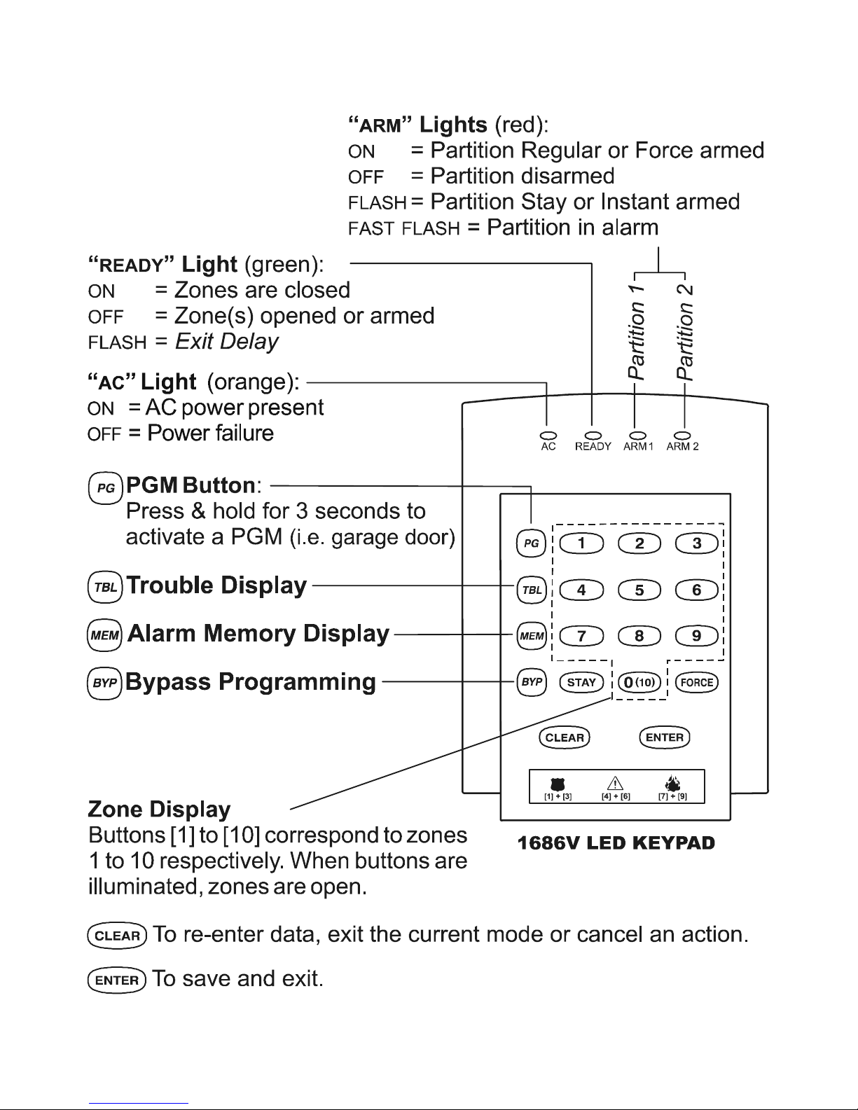
Figure 2-1: Overview of the 1686V LED Keypad
Spectra LED Keypads 7
Page 8

2.2 KEYPAD INDICA TOR LIGHTS
All Spectra LED Keypads include colored lights which
convey the current status of your system. As explained in
Figure 2-1 the state of each light represents a specific
condition in your system.
2.3 ZONE DISPLAY
The numerical buttons on the 1686V/H Keypads are
designed to communicate the status of the zones in your
system. Each button corresponds to a zone in your system. If
a button’s light is off (extinguished), the corresponding zone is
closed. If a button’s light is on (illuminated), the corresponding
zone is open (i.e. open door, movement detected, etc.).
2.4 ALARM MEMORY DISPLAY
If an alarm has occurred on a zone, the [MEM] button will
illuminate. All zones where alarms occurred will be stored in
memory. After disarming the system, press the [
to illuminate the buttons corresponding to the zones that
were in alarm (see Zone Display in section 2.3). To exit the
Alarm Memory Display,press[
CLEA R] button. The system
MEM] button
will erase the contents of the Alarm Memory every time the
system is armed.
8User’sGuide
Page 9

2.5 TROUBLE DISPLAY
Your alarm system continuously monitors fourteen possible
trouble conditions. Most of these trouble conditions can be
reported directly to your security company. When a trouble
condition occurs, [
The keyp adcan be progra mme dto emita “
TBL] will illuminate.
BEEP”every
5 seconds whenever a new trouble condition has
occurred. Press the [
TRBL]buttontostopthe“Trouble
Beep”.
How Do I Access the Trouble Display?
1) Press the [
The [TBL] button will flash and any numbers corresponding to an
existing trouble condition will illuminate.
TBL] button
2) Read the corresponding explanation of the trouble
from the Trouble List. If no repair instructions are
given, contact your Security Company for repairs.
3) Press the [
CLEAR] buttontoexit
We strongly suggest that you inform your
Security Company of the trouble and allow them
to service your system.
Spectra LED Keypads 9
Page 10

Trouble List
2.5.1 No or Low Battery Trouble [1]
When the [1] button illuminates, the backup battery is
disconnected or the battery voltage is getting low.
2.5.2 Wireless Transmitter Battery Low [2]
When the [2] button illuminates, the battery voltage in one or
more Wireless Transmitters is getting low. Also, the device’s
yellow light will flash.
2.5.3 Power Failure [3]
When the [3] button illuminates, the system has detected a loss
of AC power. This trouble usually occurs during a power failure. If
a power failure is not occurring in your establishment and this
trouble appears, contact your Security Company for service.
2.5.4 Bell/PGM2 Disconnected Trouble [4]
When the [4] button illuminates, the bell, siren, or any device
connected to the PGM2 is no longer connected to your alarm
system.
2.5.5 Bell Current Failure [5]
During an alarm, the bell output, which uses a fuseless circuit, will
automatically shut down if the current exceeds its limits. If this
occurs, the [5] button will illuminate. When the system is disarmed,
the current is cut from the bell output and the Trouble warning may
extinguish, but the Trouble may re-occur during the next alarm if
the situation is not corrected.
2.5.6 Auxiliary Current Failure [6]
The auxiliary output, which supplies power to your alarm
system’s accessories, uses a fuseless circuit to protect the
10 User’s Guide
Page 11

power supply against current overload and automatically shuts
down if the current exceeds 1.1A. If this occurs, the [6] button
will illuminate.
2.5.7 Communication Failure [7]
If your alarm system is monitored and it could not communicate
with the Security Company, the [7] button will illuminate.
2.5.8 Timer Loss [8]
When the [8] button illuminates, your alarm system’s clock
must be re-programmed. Th is is the only t ro uble that we
recommend that you correct.
To re-program the clock press the [8] button after Step 2 from
the Tr ouble Display (see “How Do I Access the Trouble
Display?” at the beginning of section 2.3) and enter the current
time using the 24-hour clock (i.e. 8:30PM = 20:30). Also, refer
to section 5.4 and Appendix A.
2.5.9 Tamper/Zone Wiring Failure [9]
When the [9] button illuminates, a w iring problem is occurring
on one or more zones.
To view which zones are experiencing trouble, press the [9]
button after Step 2 from the Trouble Display (see “How Do I
Access the T r ouble Display?” at the beginning of section 2.3)
(see Zone Display: section 2.3).
2.5.10 Telephone Line Monitoring Failure [10]
When the [10] button illuminates, the system has not detected
the presence of a telephone line for more than 30 seconds.
Spectra LED Key pads 11
Page 12

2.5.11 Fire Zone Trouble [STAY]
When the [STAY] button illuminates, a wiring problem on the fire
zone is occurring.
2.5.12 Module Loss [ BYP]
When a module is no longer communicating with your system, the
[
BYP] button illuminates.
2.5.13 Wireless Transmitter Supervision Loss [MEM]
When a wireless transmitter is no longer communicating with its
receiver or its batteries are disconnected, [
MEM] illuminates.
.
To view on which zones the Wireless T ransmitt ers are
experiencing trouble, press the [
MEM] buttonafterStep2from
the Tr ouble Display (see “How Do I Access the Trouble
Display?” at the beginning of section 2.3) (see Zone Display:
section 2.3).
2.5.14 Keypad Fault [FORCE]
If for any reason your keypad is no longer communicating with
your alarm system, the keypad will emit four consecutive beeps
at 3-second intervals. Press any button on the keypad to
terminate the “beeping” sequence. The [
TBL] button will flash
and the [
FORCE] button will illuminate. When com munication
has been restored, the keypad will resume its functions.
12 User’s Guide
Page 13

2.6 PARTITIONING
Your Spectra system is equipped with a partitioning feature
which can divide your alarm system into two distinct areas
identified as Partition 1 and Partition 2. Partitioning can be
used in installations where shared security systems are
more practical, such as a home office or warehouse
building. When partitioned, each zone, each User Code
and many of your system's features can be assigned to
either Partition 1, Partition 2, or both partitions.
If the system is not partitioned, all zones, User
Codes, and features will be recognized as
belonging to Partition 1.
Spectra LED Key pads 13
Page 14

3.0 PROGRAMMING ACCESS CODES
Access Codes are personal identification numbers that
allow you to enter certain programming modes, arm or
disarm your system as well as activate or deactivate PGMs
(see section 5.5). The Spectra security system supports
the following:
1 System Master Code
2 Master Codes
45 User Access Codes (including 1 Duress code)
For information on how each Access Code can arm or disarm
the system refer to the System Checklist in section 8.0.
3.1 SYSTEM MASTER CODE (Default: 123456)
The System Master Code can arm or disarm any partition
using any of the methods described in this section and can
create, modify or delete any User Access Code (see
section 3.4).
3.2 MASTER CODES
Master Code 1 is permanently assigned to Partition 1 and
can be used to create, modify or delete User Access Codes
(see section 3.4) that are assigned to Partition 1.
Master Code 2 is permanently assigned to Partition 2
(except when partitioning is disabled, Master Code 2 will be
14 User’s Guide
Page 15

assigned to Partition 1) and can be used to create, modify
or delete User Access Codes (see section 3.4) that are
assigned to the same partition.
Master Codes cannot modify or delete User Access
Codes assigned to both partitions. Only the System
Master Code can modify or delete User Access
Codes assigned to both partitions.
3.3 DURESS CODE
If you are forced to arm or disarm your system, entering the
Access Code assigned to User 048 willarmordisarmthe
system and immediately transmit a silent alert (Duress
Code) to the Security Company.
3.4 PROGRAMMING ACCESS CODES
Your system can use either 4- or 6-digit Access Codes (see
page 35), where each digit can be any value from 0 to 9.
Six-digit codes are considered more difficult to “crack” and
therefore, more secure. Avoid programming simple or
obvious access codes, such as your telephone number,
address or codes such as 1234.
Spectra LED Key pads 15
Page 16

How Do I Program Access Codes?
1) Press [
2) Enter your [
[ENTER] button flashes
ENTER]
MASTER CODE]
3) Enter 3-digit [SECTION] (see Table 1)
The [NUMBER] corresponding to the first d igit of the existing
code (if pr ogrammed) and the [
(see Appendix A)
ENTER] button will illuminate
4) Enter a new 4 or 6-digit [ACCESS CODE]
[ENTER]buttonflashes.Returntostep3toenternextcodeor
press [
CLEAR]toexit.
How Do I Delete Access Codes?
1) Repeat steps 1 to 3 (see above)
2) Press the [
FORCE] button once for each digit in the Access
Code (4 or 6 times) until the keypad emits a
“
CONFIRMATION BEEP”thenpressthe[CL EAR] button to exit.
Table 1: User Code Sections
Section User Codes
[001] User Code 001 = System Master Code
[002] User Code 002 = Master Code 1
[003] User Code 003 = Master Code 2
[004] to [047] User Code 004 to User Code 047
[048] User Code 048 or Duress Code
16 User’s Guide
Page 17

4.0 ARMING & DISARMING
Take full advantage of your Spectra system by familiarizing
yourself with all the arming methods.
If your system is not p artitioned (section 2.6), the
system considers everything as belonging to Partition 1
4.1 EXIT DELAY
After entering a valid arming sequence, an Exit Delay Timer
will provide you with enough time to exit the protected area
before the system arms. The “
READY” Light will flash during
the Exit Delay and the keypad may beep. During the final 10
seconds, the beeping and the light will accelerate.
4.2 DISARMING &DEACTIVATING AN ALARM
To disarm an armed system or an alarm, enter your access
code. An entry point, like the front door, will be programmed with
one of two Entry Delay Timers. When an entry point is opened,
your alarm system will not generate an alarm until this timer
elapses or you disarm the system. Any user can disarm a
partition they have been assigned to, except users assigned
with the Arm Only Option. To disarm alarms generated by a
Delayed Fire Zone, please refer to section 6.0.
.
How Do I Deactivate an Alarm?
Enter your [
ACCESS CODE]
Spectra LED Key pads 17
Page 18

How Do I Disarm the System?
For a Stay or Instant Armed system, go to Step 2.
1) Enter through a designated entry point (i.e. front door).
The keypad will “beep” during the Entry Delay.
2) Enter your [ACCESS CODE]
After the “CONFIRMATION BEEP”, the “ARM” Light will turn off.
IF YOU HAVE ACCESS TO BOTH PARTITIONS (see section 2.6):
3) Buttons
[1]
and
[2]
will flash. Press the button
corresponding to the desired partition. For both partitions,
press the other button after the “C
ONFIRMATIONBEEP
”.
4.3 REGULAR ARMING
This method, c ommonly used for day-to-day arming, will
arm all the zones in the selected partition.
How Do I Regular Arm?
1) Close all zones in the desired part iti on.
2) Enter your [
IF YOU HAVE ACCESS TO BOTH PARTITIONS (see section 2.6):
ACCESS CODE]
3) Buttons [1] and [2] will flash . Pres s the button
corresponding to the desired partition. For both partitions,
press the other button after the “C
18 User’s Guide
ONFIRMATION BEEP”.
Page 19

When you have correctly armed the system, the “ARM”
Light corresponding to the armed partition will turn on and
the Exit Delay (see section 4.1) will initiate. Please note
that Regular Arming canalsobeactivatedusingAuto-
Arming (see section 4.9), a Keyswitch (see section 4.8), or
One-Touch Arming (see section 4.7).
4.4 STAY ARMING
This method allows you to remain in the protected area
while partially arming the system. S tay Zones are zones
that are bypassed when Stay Arming. For example, when
you go to sleep at night, doors and windows can be armed
without arming other zones like motion detectors.
How Do I Stay Arm?
1) Close all zones in the desired partition (except Stay
Zones).
2) Press the [
3) Enter your [
IF YOU HAVE ACCESS TO BOTH PARTITIONS (see section 2.6):
STAY] button
ACCESS CODE]
4) Buttons [1] and [2] will flash . Pres s the button
corresponding to the desired partition. For both partitions,
press the other button after the “C
When you correctly Stay Arm the system, the “
corresponding to the armed partition will flash and the Exit
Delay will be initiated (see section 4.1). Stay Arming can
ONFIRMATION BEEP”.
ARM” Light
Spectra LED Key pads 19
Page 20

also be activated using Auto-Arming (see section 4.9), a
Keyswitch (see section 4.8) or One-Touch Arming (see
section 4.7).
4.4.1 Instant Arming
After Stay Arming the system and during its Exit Delay, press
andholdthe[
“
CONFIRMATION BEEP”. The system is then Instant Armed.
STAY] button for 3 seconds. You should hear a
Therefore, any armed zone that is breached will immediately
generate an alarm.
If you have access to both partitions:
To Instant Arm one partition
1) Press the [
2) Ent er your [
STAY] button 1) Press the [STAY] button
ACCESS CODE] 2) Ent er your [ACCESS CODE]
To Instant Arm both partitions
3) Choose a partition 3) Press [1]
4) Press the [
5) Press and hold the [
CLEAR] button 4) Press [2]
STAY] but-
5) Press and hold the [STAY]
ton for 3 seconds
button for 3 seconds
4.5 FORCE ARMING
Force Arming allows you to rapidly arm the system without
waiting for all zones in the s ystem to close. During Force
Arming,aForce Zone is considered “deactivated” until it
closes, then the system will arm that zone. Force Arming is
commonly used when a motion detector is protecting the
area occupied by a keypad. For example, when arming and
20 User’s Guide
Page 21

the motion detector is a Force Zone, the system will allow
you to arm even if the zone is open.
How Do I Force Arm?
1) Close zones in the desired partition (except Force
Zones).
2) Press the [
3) Enter your [
IF YOU HAVE ACCESS TO BOTH PARTITIONS (see section 2.6):
FORCE] button
ACCESS CODE]
4) Buttons [1] and [2] will flash. Press the button
corresponding to the desired partition. For both partitions,
press the other button after the “C
When you correctly Force Arm the system, the “
ONFIRMATION BEEP”.
ARM”Light
corresponding to the armed partition will turn on and the
Exit Delay will initiate (see section 4.1). Force Arming can
also be activated by using One-Touch Force Arming (see
section 4.7.4).
4.6 MANUAL BYPASS PROGRAMMING
Manual Bypass Programming allows you to program the
alarm system to ignore (deactivate) specified zones the next
time the system is armed. For example, you may wish to
bypass certain zones when workers are renovating part of
your establishment. Please note that a Fire Zone cannot be
bypass ed.
Spectra LED Key pads 21
Page 22

How do I Program Bypass Entries?
1) Press the [
2) Enter your [
BYP] button.
ACCESS CODE].(seeNote1)
3) Illuminate the button(s) corresponding to the zone(s) you
wish to bypass by pressing the corresponding button.
Press the button again to turn it off. Press the [FORCE]
button to erase all the current zone bypass entries.
4) Once you have entered the desired bypass entries,
press the [
THE [BYP] button will turn on when zones are bypassed. The
next time the system is armed, the zones will be bypassed.
ENTER] button to accept these entries.
NOTE1: If you have access to both partitions, buttons [1]
and [2] will flash. Press the button corresponding to the
desired partition. The [
BYP] button will flash and any zones
that are already bypassed will illuminate.
4.6.1 Bypass Recall Feature
After disarming the system, the bypass entries are erased.
The Bypass Recall Feat ure reinstates the previous bypass
entries s aved in memory. This eliminates the need to manually
re-program the bypass entries every time you arm the system.
How Do I Recall Bypass Entries?
1) Press the [
2) Enter your [
3) Press the [
BYP] button.
ACCESS CODE].(seeNote1)
BYP] button.
Previously bypass ed zones will illuminate.
4) Press the [ENTER] button.
22 User’s Guide
Page 23

4.7 ONE-TOUCH ARMING
One-Touch Arming allows you to arm the system without
using an access code.
NOTE2: If both partitions are enabled and you activate a
One-Touch feature, buttons [1] and [2] will flash. Press
the button corresponding to the desired partition(s).
4.7.1 One-Touch Regular Arming
Press and hold the [ENTER] button for 3 seconds (see Note2)to
arm all zones in the partition. You can use this feature to allow
specific individuals like service personnel (i.e. cleaners) to arm
without giving them access to any other alarm system
operations. For details on Regular Arming, refer to section 4.3.
4.7.2 One-Touch Stay Arming
Press and hold the [STAY] button for 3 seconds (see Note2)to
arm all zones not defined as Stay Zones. For details on Stay
Arming, refer to section 4.4.
4.7.3 Fast Exit
WHEN THE SYSTEM IS ALREADY STAY ARMED: this feature will allow
youto exitalready armedpremisesand keepthe systemarmed.
Exit and St ay Arm: Press and hold the [
(see Note2)tostarttheExit Delay (see section 4.1). When the Exit
STAY] button for 3 seconds
Delay elapses, the system will return to Stay Arming.
Exit and Regular Arm: Press and hold the [
seconds (see Note2)tostarttheExit Delay (see section 4.1).
When the Exit Delay elapses, the system will switch to Regular
ENTER] button for 3
Spectra LED Key pads 23
Page 24

Arming (see section 4.3).
Exit and Force Arm: Press and hold the [
seconds (see Note2)tostarttheExit Delay (see section 4.1).
When the Exit Delay elapses , the system will switch to Force
Arming (see section 4.5).
FORCE] button for 3
4.7.4 One-Touch Force Arming
Press and hold the [FORCE] button for 3 seconds (see Note2)to
bypass any open Force Zones. For details on Force Arming,
refer to section 4.5.
4.7.5 One-Touch Bypass Programming
Press and hold the [BYP] button for 3 seconds (see Note2)to
access Bypass Progr amm ing Mode(see section 4.6).
4.8 KEYSWITCH ARMING
Akeyswitchcanbeusedtoarmanddisarmthesystem.A
keyswitch is assigned to and programmed to Stay Arm
(see section 4.4) or Regular Arm (see section 4.3) a
specific partition. A keyswitch can function as a Maintained
or Momentary keyswitch.
To arm the system using a Maintained Keyswitch, set the
keyswitch to the “on” position. To disarm the system set the
keyswitch to the “off” position.
To arm the system using a Momentary Keyswitch, set the
keyswitch to the “on” position then turn it back to the “off”
position. Repeating this sequence will disarm the system.
24 User’s Guide
Page 25

4.9 AUTO-ARMING
The Spectra alarm system can be programmed to
automatically arm upon the following two conditions.
4.9.1 Timed Auto Arming
The alarm system can automatically arm itself at a specified
time everyday . As with Regular Arming (see section 4.3), the
system will not arm if a zone is open. If this occurs, the system
will not arm until the next day. Your installer enables this option,
but you can program the time of day the system will
automatically arm.
How do I program the Auto-Arm Timer?
1) Press the [
2) Enter your [
[ENTER] button flashes
ENTER] button
MASTER CODE]
3) Enter [101] for Partition 1 or [102] for Partition 2 (see
Appendix A)
4) Enter the desired [
TIME]
Example: 6:15PM = 18:15
A 60-second Exit Delay (see section 4.1) will start before
the system arms. At this point, Auto-Arming can be
cancelled by entering your access code.
4.9.2 “No Movement” Auto Arming
Your panel can be programmed to arm the system and/or send a
report if no zone activity occurs for a pre-programmed amount of
time. This is a particularly useful feature when supervising an
individual with chronic health problems or who lives alone.
Spectra LED Key pads 25
Page 26

5.0 ADDITIONAL FEATURES
Each keypad must be Chime Programmed and Muted
separately. Keypad Muting must be re-programmed if
your system suffers a total power loss.
Whenyoupressandholdabuttonandthekeypad
emits a “C
ONFIRMATION BEEP”, the chime feature
has been enabled for that zone or Keypad Muting
has been enabled for that keypad. If the keypad
emits a “R
EJECTION BEEP”, these features have
been disabled.
5.1 PROGRAMMING CHIME ZONES
This feature allows you to program which zones will be
“Chime Enabled”.A“Chime Enabled” zone will advise y ou
every time it is opened by causing your keypad to emit a
rapid intermittent beep tone (
and hold any button from [1] to [10] for 3 seconds to
BEEP-BEEP-BEEP-BEEP). Press
activate or deactivate Chiming for zones 1 to 10. For
example, press and hold the [1] button to enable chiming
on zone 1.
5.2 KEYPAD MUTING
Press and hold the [CLEAR] button for 3 seconds to enable
or disable keypad muting. When muted, the keypad will
only emit the “C
beep when a button is pressed.
26 User’s Guide
ONFIRMATION BEEP”, “REJECTION BEEP”, and
Page 27

5.3 PANIC ALARMS
In case of emergency, the Spectra system can provide three
panic alarms that can immediately generate an alarm after
simultane ously pressing and holding two specific buttons for
two seconds. Based on your needs, these panic alarms can
generate audible alarms (sirens or bells) or silent alarms,
both of which can send a message to your Security
Company. The three different panic alarms can
communicate specific messages to your monitoring station.
For instance, pressing [1] & [3] can mean “call the police”
or anything you require.
1) Press & hold buttons [1] and [3] for the police.
2) Press & hold buttons [4] and [6] for a medical alarm.
3) Press & hold buttons [7] and [9] for a fire alarm.
5.4 PROGRAM TIME (CLOCK)
How do I program the System Clock?
1) Press the [
2) Enter [
[ENTER] button flashes
MASTER CODE]
3) Enter [100] (see Appendix A)
ENTER] button
4) Enter the desired
Example: 6:15PM = 18:15
[TIME].
Spectra LED Key pads 27
Page 28

5.5 PGM BUTTON (PROGRAMMABLE OUTPUTS)
Your Spectra system may include one or more
programmable outputs (PGMs). When a specific event or
condition occurs in the system, the PGM can be used to
reset s moke detectors, activate light switches in your home
or office, open/close garage doors and much more. A PGM
canalsobeprogrammedtoactivatewheneverthe[
PG]
button is pressed and held for 3 seconds.
5.6 QUICK FUNCTION KEYS
Upon request of your installer or Security Company you
may have to perform one of the following. Press:
5.6.1 T
[ENTER]+[MASTER CODE]+[MEM]
If your system is monitored by your Security Company, this
feature will send a test report code to the Security Company.
EST REPORT
5.6.2 CALL PC
[ENTER]+[MASTER CODE] + [BYP]
Will initiate a call to the Security Company that is using the
upload/download diagnostic software.
5.6.3 Answer PC
[ENTER]+[MASTER CODE] + [FORCE]
Will force your security system to answer a call made by your
Security Company that is using the upload/download
diagnostic software.
28 User’s Guide
Page 29

5.6.4 Cancel Communication
[ENTER]+[MASTER CODE] + [STAY]
Cancels all communication with the upload/download diagnostic
software if it has been initiated.
5.7 KEYPAD BACKLIGHT
The illumination level behind the keys can be modified to
suit the user’s needs. There are four backlight levels. The
[
MEM] key is used to set the desired level. Each
consecutive push of the [
MEM] key will increase the
backlight level until the maximum level is reached. After
reaching the maximum level, the backlight level will return
to the lowest level and the whole process is repeated. To
change the backlight level:
How do I modify the backlight?
1) Press and hold the [MEM] key for 3 seconds
2) The [
3) Press the [
MEM] key will illuminate
MEM] key to set the desired backlight
level
4) Press [
CLEAR] or [ENTER] to exit
Spectra LED Key pads 29
Page 30

6.0 FIRE ALARMS
Upon a fire alarm, the bell/siren will emit three “squawks” at
2 second intervals until silenced or reset by entering a valid
access code. If the zone is a DelayedFireZone, there is a
delay before the system contacts the Security Company.
This will prevent unnecessary reporting of false alarms. If
there is no fire condition, contact your Security Company
immediately to avoid an unnecessary response.
WhatdoIdoifaDelayedFireZonewassetoff
accidentally?
1) Press the [
CLEAR] button within 30 seconds of the alarm.
2) Try to correct the problem.
3) If the problem persist s , the alarm will sound again. Press
CLEAR] again.
[
These steps will instruct the system to delay reporting the fire
alarm to the Security Company (see Figure 6-1 for details).
30 User’s Guide
Page 31

Figure 6-1: Delayed Fire Zone Flowchart
Spectra LED Key pads 31
Page 32

Minimizing Fire Hazards
The three most common causes of fires:
• Cooking is the leading cause of home fires in the U.S.
It's also the leading cause of fire injuries. Cooking fires
often result from unattended cooking and human error,
rather than mechanical failure of stoves or ovens.
• Careless smoking is the leading cause of fire deaths.
Smoke detectors and smolder-resistant bedding and
upholstered furniture are significant fire deterrents.
• Heating is the second leading cause of residential fires.
However, heating fires are a larger problem in single
family homes than in apartments since the heating
systems in single family homes are often not
professionally maintained.
Fire Safety Tips
• In the event of a fire, remember time is the biggest enemy
and every second counts! Escape first, then call for help.
Develop a home fire escape plan and designate a
meeting place outside. Make sure everyone in the family
knows two ways to escape from every room. Practice
feeling your way out with your eyes closed. Never stand
up in a fire, always crawl low under the smoke and try to
keep your mouth covered. Never return to a burning
building for any reason; it may cost you your life.
• Finally , having at least one working smoke alarm
dramatically increases your chances of surviving a fire.
And remember to practice a home escape plan frequently
with your family.
32 User’s Guide
Page 33

Providing a Fire Warning System
Household fires are especially dangerous at night. Fires
produce smoke and deadly gases that can overcome
occupants while they sleep. To warn against fire, smoke
detectors should be installed outside each separate
sleeping area in the immediate vicinity of the bedrooms
and on each additional story of the family living unit,
including basements.
7.0 TESTING & MAINTENANCE
With the system disarmed and the “READY” Lig ht on, activ a t e
motion detectors by walking in the protected area. Open and
close protected doors and verify that the corresponding button
illuminates. Your installer can advise you of the best way to
test your particular system.
Do not use open flame or burning materials to test your fire
detection devices. Contact your installer for safe methods
of testing your system.
Under normal use, your system requires virtually no
maintenance other than regular testing. It is recommended
that the standby battery be changed every three years.
Speak to your installer about the necessary tests and at
what frequency they should be performed.
Spectra LED Key pads 33
Page 34

8.0 SYSTEM CHECKLIST
Zone Description
Is this system partitioned? Yes ! No !
Partition 1 =
_______________________________________
Partition 2 =
_______________________________________
Zone # and
Description
01:______________
02:_____________
Keyswitch? Y ! N !
Type:____________
03:______________
Fire Zone? Y ! N !
Delayed? Y ! N !
04:______________
05:______________
Partition
Byp Stay Force 24Hr
1or2
Entry
Delay
____ !! ! ! !
____ !! ! ! !
____ !! ! ! !
____ !! ! ! !
____ !! ! ! !
06:______________
07:______________
08:______________
09:______________
10:______________
11:______________
34 User’s Guide
____ !! ! ! !
____ !! ! ! !
____ !! ! ! !
____ !! ! ! !
____ !! ! ! !
____ !! ! ! !
Page 35

Zone # and
Description
Partition
1or2
Entry
Byp Stay Force 24Hr
Delay
12:______________
13:______________
14:______________
15:______________
16:______________
____ !! ! ! !
____ !! ! ! !
____ !! ! ! !
____ !! ! ! !
____ !! ! ! !
Access Codes
For security reasons, write only the user’s name and not his or
her access code. 4-Dig it Codes ! 6-Digit Codes !
User # and Name
Partition
1or2
Arm
Byp Stay Force
Only
PGM
Only
001:___________
System Master Code
Default: 123456
002:___________
Master Code 1
003:___________
Master Code 2
004:___________
005:___________
006:___________
007:___________
1&2
!!!
!!
____ !! ! ! !
____ !! ! ! !
____ !! ! ! !
____ !! ! ! !
____ !! ! ! !
____ !! ! ! !
008:___________
____ !! ! ! !
Spectra LED Key pads 35
Page 36

User # and Name
Partition
1or2
Byp Stay Force
Arm
Only
PGM
Only
009:___________
010:___________
011:___________
012:___________
013:___________
014:___________
015:___________
016:___________
017:___________
018:___________
____ !! ! ! !
____ !! ! ! !
____ !! ! ! !
____ !! ! ! !
____ !! ! ! !
____ !! ! ! !
____ !! ! ! !
____ !! ! ! !
____ !! ! ! !
____ !! ! ! !
019:___________
020:___________
021:___________
022:___________
023:___________
024:___________
025:___________
026:___________
027:___________
028:___________
____ !! ! ! !
____ !! ! ! !
____ !! ! ! !
____ !! ! ! !
____ !! ! ! !
____ !! ! ! !
____ !! ! ! !
____ !! ! ! !
____ !! ! ! !
____ !! ! ! !
029:___________
36 User’s Guide
____ !! ! ! !
Page 37

User # and Name
Partition
1or2
Byp Stay Force
Arm
Only
PGM
Only
030:___________
031:___________
032:___________
033:___________
034:___________
035:___________
036:___________
037:___________
038:___________
039:___________
____ !! ! ! !
____ !! ! ! !
____ !! ! ! !
____ !! ! ! !
____ !! ! ! !
____ !! ! ! !
____ !! ! ! !
____ !! ! ! !
____ !! ! ! !
____ !! ! ! !
040:___________
041:___________
042:___________
043:___________
044:___________
045:___________
046:___________
047:___________
048:___________
Duress: Y ! N !
____ !! ! ! !
____ !! ! ! !
____ !! ! ! !
____ !! ! ! !
____ !! ! ! !
____ !! ! ! !
____ !! ! ! !
____ !! ! ! !
____ !! ! ! !
Spectra LED Key pads 37
Page 38

Special Buttons and Features
! [
ENTER] One-touch Regular Arming is activated
STAY] One-touch Stay Arming is activated
! [
! [
FORCE] One-touch Force Arming is activated
! [
BYP] One-t ouch Manual Bypass Programming is activated
Panic Alarms:
[1] & [3] Police or __________ ! Silent ! Audible !"Off
[4] & [6] Aux. or ___________ ! Silent ! Audible !"Off
[7] & [9] Fire or ___________ ! Silent ! Audible !"Off
PGMs:
PGM 1:
___________________________________________
PGM 2:
___________________________________________
PGM 3:
___________________________________________
System Timers
Enter and exit your premises through the designated doors.
Exit Delay 1 (Partition 1): _______sec. = time to exit site
Exit Delay 2 (Partition 2): _______sec. = time to exit site
Entry Delay 1 = _______sec. = time to disarm before
alarm; enter through zone #___________
Entry Delay 2 = _______sec. = time to disarm before
alarm; enter through zone #___________
Alarm will activate siren or bell for ______ min.
38 User’s Guide
Page 39

Other Information
Installed by:__________________ Date: ____________
Serviced by:__________________ Tel: ______________
Monitored by:_________________Tel:_______________
Your account number: ____________________________
Alarm transformer location:________________________
on circuit #:____________
Location of Telephone Connections:
______________________________________________
Spectra LED Key pads 39
Page 40

9.0 APPENDIX A
Your Spectra keypad can display data one of two ways
when you to program the following parameters :
• User Access Codes (see section 3.4)
• System’s Clock (see section 2.5.8 & section 5.4)
• Auto-Arm Time (see section 4.9)
Do not read the following if you have not read the
above mentioned sections.
After entering the 3-digit section you wish to program, the
ENTER] button will flash. If a value is programmed, the
[
number corresponding to the first digit of the programmed
value will also illuminate. At this point, you can begin
entering the required data. After entering a digit, the
number corresponding to the following programmed digit
will illuminate and so forth. For example, if you wish to
change User C ode 004 from 123456 to 454545, after
entering section [004], button [1] will turn on. Press the [4]
button and button [2] will turn on, then press the [5] button
and button [3] will turn on...
OR
After entering the desired 3-digit section and before
entering any data, press the [
Data Display Mode.The[
ARM1], [ARM2] and “READY” Lights
ENTER] button to access the
will flash. Once in the Data Display Mode, pressing the
[
ENTER] button will scroll through the digits of the current
section. When viewing the last digit in the section, pressing
the [
40 User’s Guide
ENTER] button w ill automatically exit the s ection.
Page 41

NOTES
_______________________________________
_______________________________________
_______________________________________
_______________________________________
_______________________________________
_______________________________________
_______________________________________
_______________________________________
_______________________________________
_______________________________________
_______________________________________
_______________________________________
_______________________________________
_______________________________________
_______________________________________
_______________________________________
_______________________________________
_______________________________________
_______________________________________
_______________________________________
_______________________________________
_______________________________________
_______________________________________
Spectra LED Key pads 41
Page 42

Warranty
The Seller warrants its products to be free from defects in
materials and workmanship under normal use for a period
of one year . Except as specifically stated herein, all express
or implied warranties whatsoever , statutory or otherwise,
including without limitation, any implied warranty of
merchantability and fitness for a particular purpose, are
expressly excluded. Because Seller does not install or
connect the products and because the products may be
used in conjunction with products not manufactured by
Seller, Seller cannot guarantee the performance of the
security system. Seller obligation and liability under this
warranty is expressly limited to repairing or replacing, at
Seller's option, any product not meeting the specifications.
In no event shall the Seller be liable to the buyer or any
other person for any loss or damages whether direct or
indirect or consequential or incidental, including without
limitation, any damages for lost profits, stolen goods, or
claims by any other party caused by defective goods or
otherwise arising from the improper, incorrect or otherwise
faulty installation or use of the merchandise sold.
Page 43

Page 44

780 boul. Industriel, St. Eustache, Montréal, Québec J7R 5V3
Fax: (450) 491-2313 www.paradox.ca
PRINTED IN CAN ADA 10/2001 1686EU-03
 Loading...