

Page 1
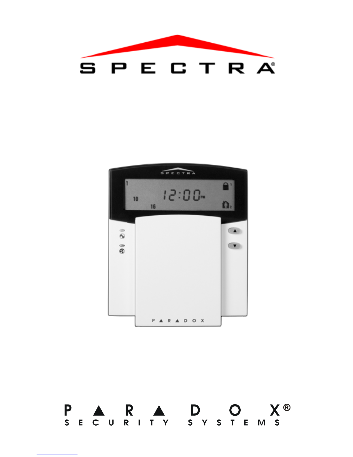
Icon LCD Keypad
(1640)
User Guide
Page 2

Page 3

Table of Contents
Introduction........................................................1
Legend................................................................... 1
Basic Operation.................................................2
Action Keys............................................................ 2
Keypad Indicator Lights......................................... 3
On-screen Icons.................................................... 4
Auditory Feedback................................................. 6
Arming & Disarming..........................................7
Exit Delay ... ... .... ... ................................................. 7
Disarming & Deactivating an Alarm....................... 7
Alarm Memory Display .......................................... 8
Regular Arming...................................................... 8
Stay Arming........................................................... 9
Instant Arming ....................................................... 9
Force Arming....................................................... 10
Manual Bypass Programming ............................. 11
One-Touch Arming.............................................. 12
Keyswitch Arming................................................ 14
Timed Auto-Arming.............................................. 14
“No Movement” Auto Arming............................... 15
Fire Alarms.......................................................... 15
Additional Features.........................................19
Programming Chime Zones.. ... ... .... ...... ... .... ... ... .. 19
Page 4

Keypad Muting .....................................................19
Panic Alarms..... ... ... .... ...................... ... ................20
Program Time ......... .... ... ... ... ... .... ... ... ................... 21
Quick Function Keys ............................................21
Keypad Settings...................................................22
Partitioning ...........................................................22
Testing & Maintenance.........................................23
Programming Access Codes......................... 24
System Master Code (Default: 123456)...............24
Master Codes.......................................................24
Duress Code ........ ... .... ... ... ... ... .... .........................25
Programming Access Codes................................25
Trouble List..................................................... 27
System Checklist............................................ 31
Page 5
1.0 Introduction
The 1640 Icon LCD Keypad allows you to easily access your
security system's functions and provide you with an easy-tounderstand display of your security system's alarm and
operational status.
All the actions performed in your security system will be
executed and displayed through the keypad. Your security
system uses advanced technology which will provide you
with reliabl e security protec tion and powerful features that are
easy to use.
Since you will communicate your instructions to the system
through your keypad, please read this manual carefully and
have your installer explain basic system operation.
1.1 Legend
= Indicates a warning.
= Indicates a note or reminder.
[Number] =
Indicates information that must be entered on
the keypad.
1640 Icon LCD Keypad 1
Page 6

2.0 Basic Operation
This section will provide an overview of the 1640’s
functionality. This includes the use of action keys, indicator
lights and visual feedback.
Many of the features in your system must be enabled by
the installer . If the feature is not programmed, the keypad
will emit a rejection beep and the action will be cancelled.
2.1 Action Keys
The 1640 has action keys with which you can access its
various functions as shown in Table 1.
Table 1: Action Keys
Name Key Description
Stay Arm Refer to Stay Arming on page 9 and
Instant Arming on page 9.
Force Arm Refer to Force Arming on page 10.
Function Key 1 Press and hold to activate devices (i.e.
garage door) or reset smoke detectors.
Speak to your installer for more details.
Function Key 2 Reserved for future use.
Zone Bypass Refer to Manual Bypass Programming
2 User Guide
on page 11.
Page 7
Name Key Description
Events in
Memory
System
Trouble
N/A Reserved for future use.
Refer to Alarm Memory Display on
page 8.
Refer to Trouble List on page 27.
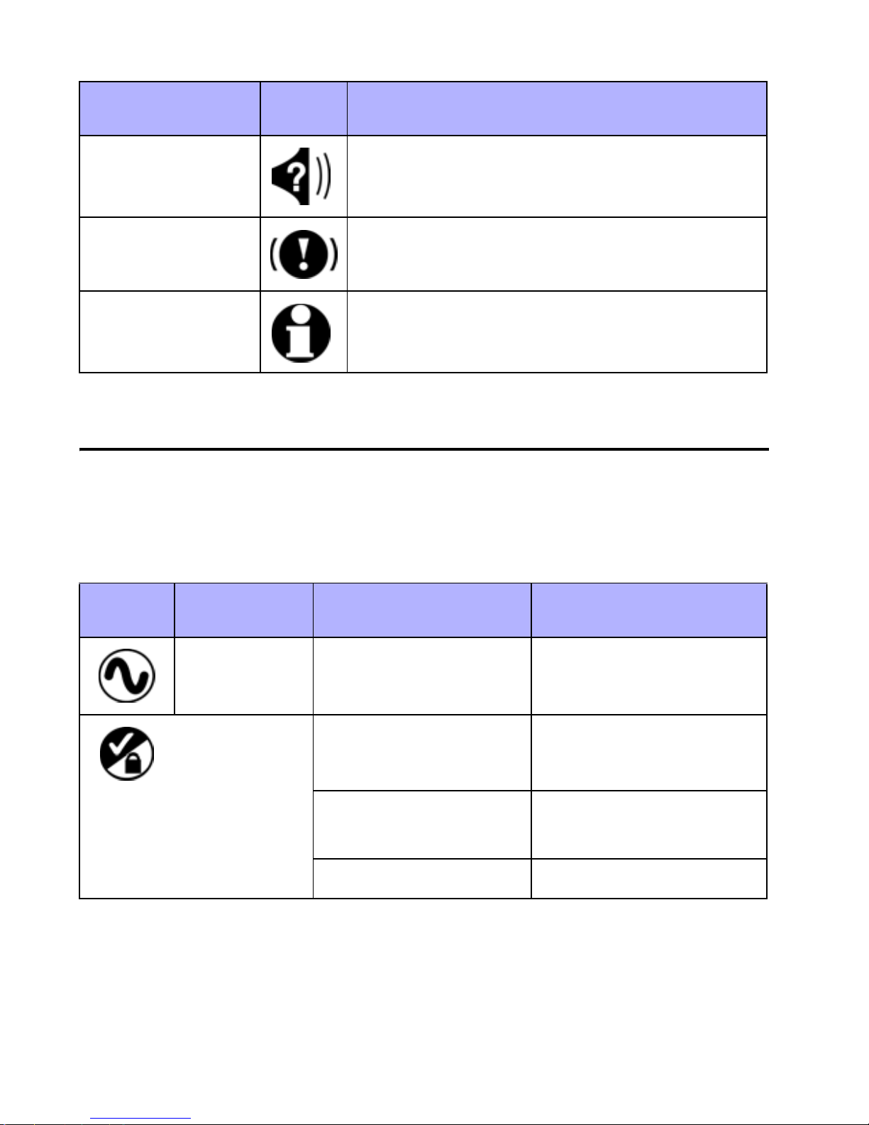
2.2 Keypad Indicator Lights
The state of each light on the 1640 keypad represents a
specific condition in your system as shown in Table 2.
Table 2: Indicator Lights
LED Name Status Description
AC Light ON
OFF
Status Light Green ON All zones closed
Green OFF Zone(s) open or in
Green flash Exit delay
Power on
Power off
tamper
1640 Icon LCD Keypad 3
Page 8
LED Name Status Description
Status Light Red ON Area(s) armed
Red OFF Area(s) disarmed
Red slow flash Stay or instant armed
Red fast flash System in alarm
Red and yellow
flash alternately
Communication bus
fault
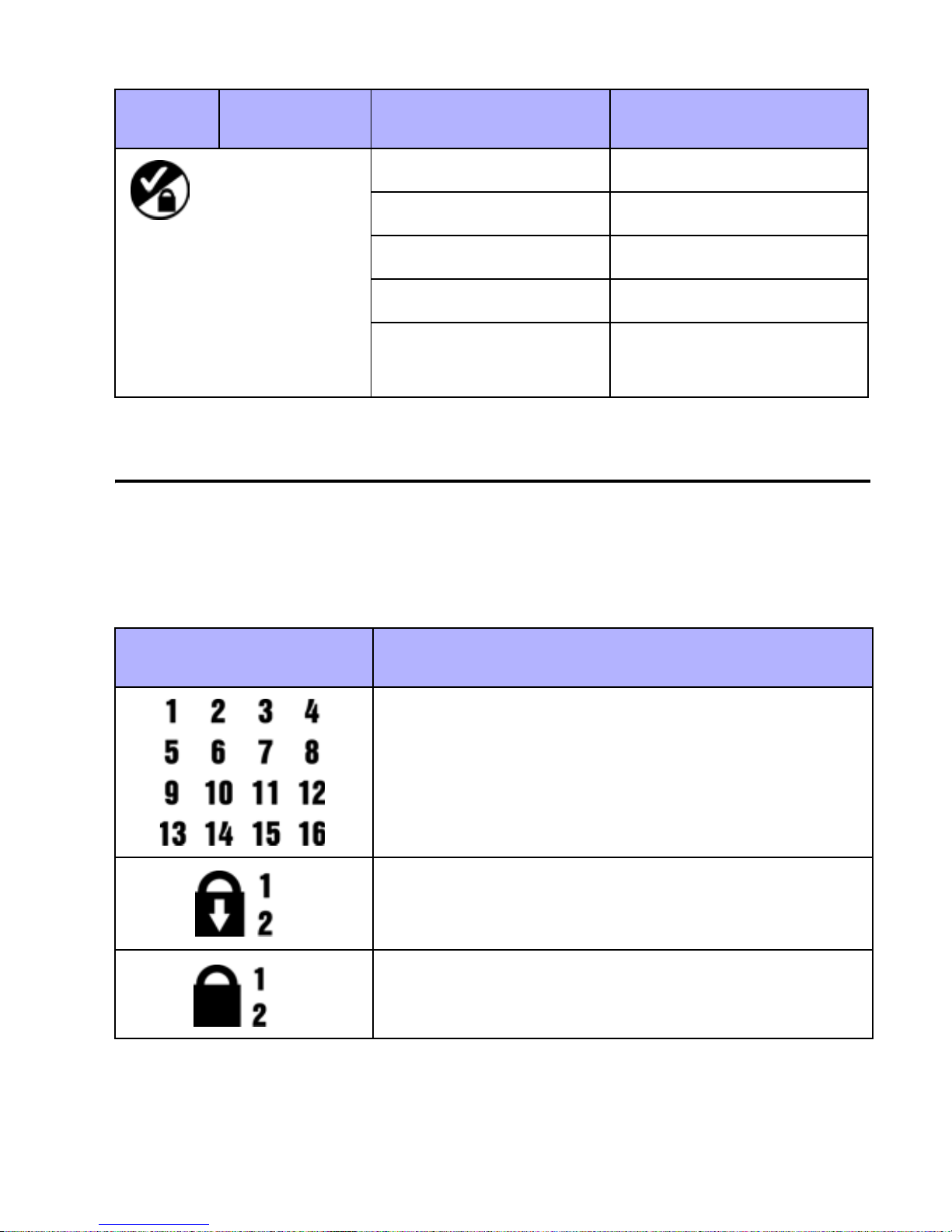
2.3 On-screen Icons
The icons on the keypad’s screen communicate your
system’s status as outlined in Table 3.
Table 3: Icon Display
Icon(s) Description
Indicates numbers corresponding to zones
or option numbers. Numbers will illuminate
to indicate that a zone is opened or when in
4 User Guide
trouble view mode will indicate the trouble.
Indicates which areas are Force Armed.
Refer to Force Arming on page 10.
Indicates which areas are Regular Armed.
Refer to Arming & Disarming on page 7.
Page 9
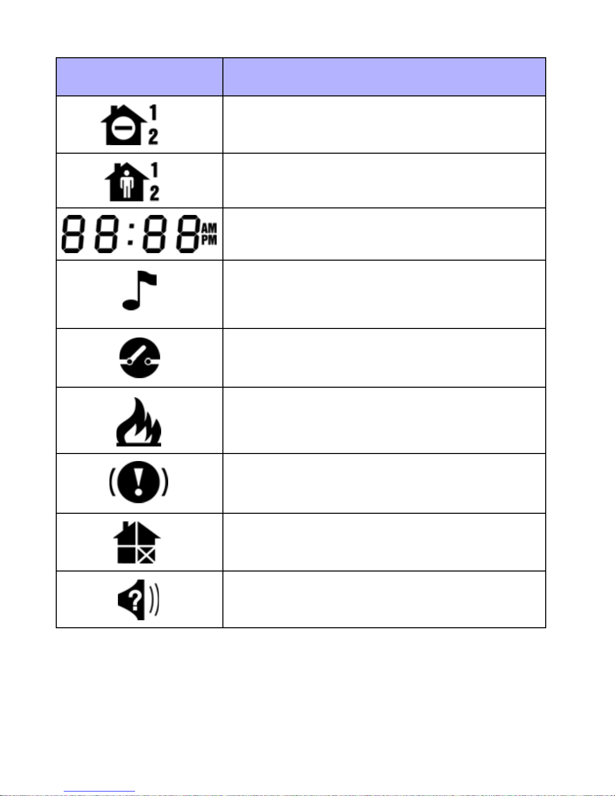
Icon(s) Description
Indicates which areas are Instant Armed.
Refer to Instant Arming on page 9.
Indicates which areas are Stay Armed.
Refer to Stay Arming on page 9.
Indicates the numerical values for the time,
sections, section data, options and codes.
Indicates which zone is in Chime Mode.
Refer to Programming Chime Zones on
page 19.
Indicates zones in tamper. Refer to Arming
& Disarming on page 7.
Indicates zones that are in Fire Alarm.
Refer to Fire Alarms on page 15
Indicates system troubles. Refer to Trouble
List on page 27.
Indicates bypassed zones. Refer to Manual
Bypass Programming on page 11.
Indicates alarms stored in memory. Refer to
Alarm Memory Display on page 8.
1640 Icon LCD Keypad 5
Page 10

2.4 Auditory Feedback
When you enter information on the keypad, it will guide you
with beep tones. You should be familiar with these:
Confirmation Beep: When an operation (i.e. arming/
disarming) is successfully entered on the keypad or when the
system switches to a new status/mode, the keypad produces
an intermittent beep tone (“
BEEP-BEEP-BEEP-BEEP”).
Rejection Beep: When the system reverts to previous st atus
or when an operation is incorrectly entered on the keypad, it
will emit a continuous beep tone (“BEEEEEEEEP”).
6 User Guide
Page 11

3.0 Arming & Disarming
Take full advantage of your Spectra system by familiarizing
yourself with all of the arming methods.
If your system is not partitioned (see Partitioning on
page 22), everything is considered as belonging to area 1.
3.1 Exit Delay
After entering a valid arming sequence, an Exit Delay Timer
will provide you with enough time to exit the protected area
before the system arms. The keypad may beep during the
Exit Delay and the icon will flash with the number of the
partition in exit delay.
3.2 Disarming & Deactivating an Alarm
To disarm an armed system or an alarm, enter your access
code. An entry point, like the front door, will be programmed
with one of two Entry Delay Timers. When an entry point is
opened, the keypad will beep until you disarm the system.
Your alarm system will not generate an alarm until this timer
elapses. To disarm alarms generated by a Delayed Fire
Zone, please refer to Fire Alarms on page 15.
How Do I Disarm an Alarm?
Enter your
[ACCESS CODE].
1640 Icon LCD Keypad 7
Page 12
3.3 Alarm Memory Display
All zones where alarms have occurred will be stored in
memory. The system will erase the contents of the Alarm
Memory every time the system is armed.
How Do I View the Alarm Menu?
1. Press the key.
2. The icon will flash and the corresponding number of
zones that were in alarm the last time the system was
armed will illuminate.
3. Press the or key to exit.
3.4 Regular Arming
This method will arm all the zones in the selected area.
How Do I Regular Arm?
1. Close all zones in the desired area.
2. Enter your [
3. If required, press the key corresponding to the desired
area, [1] or [2]. For both areas, press the other key after
the confirmation beep.
Regular Arming can also be activated using Auto-Arming
(see page 14), a Keyswitch (see page 14), or One-Touch
Arming (see page 12).
ACCESS CODE].
8 User Guide
Page 13

3.5 Stay Arming
This method allows you to remain in the protected area while
partially arming the system. Stay Zones are zones that are
bypassed when S tay Arming. For example, when you go to
sleep at night, doors and windows can be armed without
arming other zones like motion detectors.
How Do I Stay Arm?
1. Close all zones in the desired area (except Stay Zones).
2. Press the key.
3. Enter your [ACCESS CODE].
4. If required, press the key corresponding to the desired
area, [1] or [2]. For both areas, press the other key after
the confirmation beep.
Stay Arming can also be activated using Auto-Arming
(see page 14), a Keyswitch (see page 14) or One-Touch
Arming (see page 12).
3.6 Instant Arming
Instant Arming is similar to Stay Arming. Instant Arming
partially arms your system and enables you to remain in the
perimeter after the system is armed. However , Instant Arming
ignores any Entry or Exit Delays Therefore, any armed zone
that is breached will immediately generate an alarm.
1640 Icon LCD Keypad 9
Page 14
How Do I Instant Arm?
1. Stay Arm the system as outlined in Stay Arming on
page 9.
2. During the Exit Delay press and hold the key for 3
seconds.
3.7 Force Arming
During Force Arming, any open zones are temporarily
“deactivated” so you can rapidly arm the system without
waiting for all of the zones in the system to close. When the
zone closes, the system will then arm those zones. Force
Arming is commonly used when a motion detector is
protecting the area occupied by a keypad.
How Do I Force Arm?
1. Close zones in the desired area (except Force Zones).
2. Press the
key.
3. Enter your [ACCESS CODE].
4. If required, press the key corresponding to the desired
area, [1] or [2]. For both areas, press the other key after
the confirmation beep.
Force Arming can also be activated by using One-Touch
Force Arming (see page 13).
10 User Guide
Page 15

3.8 Manual Bypass Programming
Manual Bypass Programming allows you to program the
alarm system to ignore (deactivate) specified zones the next
time the system is armed. For example, you may wish to
bypass certain zones when workers are renovating part of
your establishment. Once the system is disarmed, the byp ass
entries are erased.
How Do I Bypass Zones?
1. Press the key.
2. Enter your [
ACCESS CODE]. The icon flashes.
3. If required, select the area whose zones you wish to
bypass by pressing the [1] or [2] key.
4. Enter the desired two-digit zone number (i.e. zone 3 =
03) or use the [U] or [V] buttons to scroll to the desired
zone and press the key. Repeat to unbypass the
zone. If the zone number illuminates, the zone is
bypassed. If the zone number is extinguished, the zone
is unbypassed.
5. Repeat step 4 until all desired zones are bypassed.
6. Press the key to exit. The icon will illuminate.
Can also be activated by using One-Touch Bypass
Programming (see page 13).
3.8.1 Bypass Recall Feature
After disarming the system, the bypass entries are erased.
The Bypass Recall Feature reinstates the previous bypass
1640 Icon LCD Keypad 11
Page 16

entries saved in memory. Thi s eliminates the need to
manually reprogram the bypass entries every time you arm
the system.
How Do I Recall Bypass Entries?
1. Press the key.
2. Enter your [
ACCESS CODE].
3. Select an area.
4. Press the key.
5. Press the to exit.
3.9 One-Touch Arming
One-Touch Arming allows you to arm the system without
using an access code. These features must be enabled by
your installer.
3.9.1 One-Touch Reg ular Arming
Press and hold the key for 3 seconds to arm all zones in
the area. You can use this feature to allow specific individuals
like service personnel (i.e. cleaners) to arm without giving
them access to any other alarm system operations. For
details on Regular Arming, refer to Regular Arming on
page 8.
3.9.2 One-Touch Stay Arming
Press and hold the key for 3 seconds to stay arm. For
details on Stay Arming, refer to Stay Arming on page 9.
12 User Guide
Page 17

3.9.3 Exit and Stay Arm
With the system already Stay armed, press and hold the
key for 3 seconds to start the Exit Delay (see page 7). You
can now leave the premises. When the Exit Delay elapses,
the system will return to Stay Arming.
3.9.4 Exit and Regular Arm
With the system is already Stay armed, press and hold the
key for 3 seconds to start the Exit Delay (see page 7).
You can now leave the premises. When the Exit Delay
elapses, the system will switch to Regular Arming (see
page 8).
3.9.5 Exit and Force Arm
With the system is already stay armed, press and hold the
key for 3 seconds to start the Exit Delay (see page 7). You
can now leave the premises. When the Exit Delay elapses, the
system will switch to Force Arming (see page 10).
3.9.6 One-Touch Force Arming
Press and hold the key for 3 seconds to bypass any open
Force Zones. For details on Force Arming, refer to page 10.
3.9.7 One-Touch Bypass Programming
Press and hold the key for 3 seconds to access Bypass
Programming Mode (see page 11).
1640 Icon LCD Keypad 13
Page 18

3.10 Keyswitch Arming
A keyswitch can be used to arm and disarm the system. A
keyswitch is programmed to Stay Arm (see page 9) or
Regular Arm (see page 8). A keyswitch can function as a
Maintained or Momentary keyswitch.
To arm the system using a Maintained Keyswitch, set the
keyswitch to the ON position. To disarm the system set the
keyswitch to the OFF position.
To arm the system using a Momentary Keyswitch, set the
keyswitch to the ON position then turn it back to the OFF
position. Repeating this sequence will disarm the system.
3.11 Timed Auto-Arming
You can program the time at which your alarm system will
automatically arm itself everyday.
How do I Program the Auto-Arm Timer?
1. Press the key .
2. Enter your [
3. Enter [101] for area 1 or [102] for area 2.
4. Enter the desired [
the time as either International (24hr) or U.S. (12hr)
format.
5. Select [1] for a.m. or [2] for p.m. time format. Refer
Program Time on page 21 for details concerning time
MASTER CODE].
TIME]. Note: Your installer will have set
formats.
14 User Guide
Page 19

A 60-second Exit Delay (see page 7) will start before the
system arms. Auto-Arming can be cancelled by entering
your access code.
3.12 “No Movement” Auto Arming
Your panel can be programmed to arm the system and/or
send a report if no zone activity occurs for a pre-programmed
amount of time. This is useful when supervising an individual
with chronic health problems or who lives alone.
3.13 Fire Alarms
Upon a fire alarm, the bell/siren will emit three “squawks” at 2
second intervals until silenced or reset by entering a valid
access code. If the zone is a Delayed Fire Zone, there is a
delay before the system contacts the monitoring station. This
will prevent unnecessary reporting of false alarms. If there is
no fire condition, contact your monitoring station immediately
to avoid an unnecessary response.
What Do I Do if a Delayed Fire Zone Was Activated?
1. Press the key within 30 seconds of the alarm.
2. Try to correct the problem.
3. If the problem persists, the alarm will sound again. Press
the key again.
This instructs the system to delay reporting the fire alarm to
the monitoring station (see Figure 3.1 on page 16).
1640 Icon LCD Keypad 15
Page 20

Figure 3.1: Delayed Fire Zon e Event Sequence
16 User Guide
Page 21

Minimizing Fire Hazards
The three most common causes of fires:
• Cooking is the leading cause of home fires in the U.S. It's
also the leading cause of fire injuries. Cooking fires often
result from unattended cooking and human error, rather
than mechanical failure of stoves or ovens.
• Careless smoking is the leading cause of fire deaths.
Smoke detectors and smolder-resistant bedding and
upholstered furniture are significant fire deterrents.
• Heating is the second leading cause of residential fires.
However , heating fires are a larger problem in single family
homes than in apartments since the heating systems in
single family homes are often not professionally
maintained.
Fire Safety Tips
• In the event of a fire , esca pe first, then call for help.
Develop a home fire escape plan and designate a meeting
place outside. Make sure everyone in the family knows two
ways to escape from every room. Practice feeling your
way out with your eyes closed. Never stand up in a fire,
always crawl low under the smoke and try to keep your
mouth covered. Never return to a burning building for any
reason; it may cost you your life.
• Finally, having at least one working smoke alarm
dramatically increases your chances of surviving a fire.
And remember to practice a home escape plan frequently
with your family.
1640 Icon LCD Keypad 17
Page 22

Providing a Fire Warning System
Household fires are especially dangerous at night. Fires
produce smoke and deadly gases that can overcome
occupants while they sleep. To warn against fire, smoke
detectors should be installed outside each separate sleeping
area in the immediate vicinity of the bedrooms and on each
additional story of the family living unit, including basements.
18 User Guide
Page 23
4.0 Additional Features
4.1 Programming Chime Zones
A Chime Enabled zone will advise you every time it is opened
by causing your keypad to beep.
How do I Chime Zones ?
1. Press & hold the [9] key for 3 seconds.
2. Enter the two-digit zone number of the desired zone or
use the [U] or [V] buttons to scroll to the desired zone
and press the key. Repeat to unchime the zone. If the
zone number illuminates, the zone is chimed. If the zone
number is extinguished, the zone is unchimed. To
remove chiming from all zones, press the
key .
3. Press the key to exit.
Each keypad must be Chimed separately.
4.2 Keypad Muting
When muted, the keypad will only emit the confirmation beep,
rejection beep, and beep when a key is pressed. Therefore,
when muted, the keypad will not beep during an alarm or
during the exit delay . Press and hold the key for 3 seconds
to enable or disable Keypad Muting. If the keypad emits a
confirmation beep, Keypad Muting is enabled for that keypad.
If the keypad emits a rejection beep, the feature is disabled.
1640 Icon LCD Keypad 19
Page 24

Each keypad must be Muted separately. Keypad Muting
must be reprogrammed if your system suffers a total
power loss.
4.3 Panic Alarms
In case of emergency, the Spectra system can provide three
panic alarms that can immediately generate an alarm after
simultaneously pressing and holding two specific buttons for
three seconds. Based on your needs, these panic alarms can
generate audible alarms (sirens or bells) or silent alarms and
can communicate specific messages to your monitoring
station. For instance, pressing [1] and [3] can mean “call the
police” or anything you require.
Press and hold buttons [1] and [3] for the police.
Press and hold buttons [4] and [6] for a medical alarm.
Press and hold buttons [7] and [9] for a fire alarm.
20 User Guide
Page 25

4.4 Program Time
How do I Program the Time?
1. Press the key.
2. Enter [
MASTER CODE].
3. Enter [100].
4. Enter the desired
[TIME]. Note: Your installer will have
set the time as either International (24hr) or U.S. (12hr)
format.
5. If the format is U.S., select “1” for A.M. or “2” for P.M.
6. Press the key to exit.
4.5 Quick Function Keys
Upon request of your installer or monitoring station you may
have to perform one of the following.
4.5.1 Test Report
Press the key, enter your [
MASTER CODE] and press the
key.This will send a test report code to the monitoring
station.
4.5.2 Call PC
Press the key, enter your [
MASTER CODE] and press the
key.This will initiate a call to the monitoring station that is
using the WinLoad software.
1640 Icon LCD Keypad 21
Page 26

4.5.3 Answer PC
Press the key, enter your [MASTER CODE] and press the
key. This will force your security system to answer a call
made by your monitoring station that is using the WinLoad
software.
4.5.4 Cancel Communication
Press the key, enter your [
MASTER CODE] and press the
key. This will cancel all communication with the WinLoad
software if it has been initiated.
4.6 Keypad Settings
You can modify the keypad’s setting to suit your needs.
1. Press and hold [6] for 3 seconds.
2. Press one of the following keys:
[1] Backlight: the keypad’s light (7 is the brightest).
[2] Contrast: character intensity (7 is the lightest).
[3] Scroll: time between messages (7 is the slowest).
3. Press [U] or [V] to modify the settings.
4. Press the key to save and exit.
5. Return to step 2 or press the key to exit.
4.7 Partitioning
Your Spectra system is equipped with a partitioning feature
that can divide your alarm system into two distinct areas
identified as Area 1 and Area 2. Partitioning can be used in
22 User Guide
Page 27

installations where shared security systems are more
practical, such as a home office or warehouse building. When
partitioned, each zone, each user code and many of your
system's features can be assigned to either Area 1, Area 2,
or both areas.
An area is the same as a partition. The term partition or
partitioning is a term installers use to describe the
division of secured premises into separate partitions or
areas. Only your installer can partition your premises.
If the system is not partitioned, all zones, user codes,
and features will be recognized as belonging to Area 1.
4.8 Testing & Maintenance
With the system disarmed and the light is ON, activate
motion detectors by walking in the protected area. Open and
close protected doors and verify that the corresponding key
illuminates. Your installer can advise you of the best way to
test your particular system.
Do not use open flame or burning materials to test your fire
detection devices. Contact your installer for safe methods of
testing your system.
Under normal use, your system requires virtually no
maintenance other than regular testing. It is recommended
that the standby battery be changed every three years. S peak
to your installer about the necessary tests and at what
frequency they should be performed.
1640 Icon LCD Keypad 23
Page 28

5.0 Programming Access Codes
Access codes are personal identification numbers that allow
you to enter certain programming modes, arm or disarm your
system as well as activate or deactivate PGMs.
The Spectra security system supports the following:
• One System Master Code
• Two Master Codes
• 45 User Access Codes (including one Duress Code)
If any area is armed, you cannot create, modify or delete
user access codes.
For information on how each access code can arm or disarm
the system refer to the System Checklist on page 31.
5.1 System Master Code (Default: 123456)
The System Master Code can arm or disarm any area using
any of the methods described in this section and can create,
modify or delete any user access code. Refer to
Programming Access Codes on page 25.
Do not delete the System Master Code in section [001].
If you do, the System Master Code will be lost, you will
not be able to re-program it and your system will have to
be serviced by a technician.
5.2 Master Codes
Master Code 1 is permanently assigned to Area 1 and can be
24 User Guide
Page 29

used to create, modify or delete user access codes (see
page 25) that are assigned to Area 1.
Master Code 2 is permanently assigned to Area 2 (except
when partitioning is disabled, in which case Master Code 2
will be assigned to Area 1) and can be used to create, modify
or delete user ac cess codes that are assigned to the same
area (see Programming Access Codes on page 25).
Master codes cannot modify or delete user access codes
assigned to both areas. Only the System Master Code can
modify or delete user access codes assigned to both areas.
5.3 Duress Code
If you are forced to arm or disarm your system, entering the
access code assigned to User 048 will arm or disarm the
system and immediately transmit a silent alert (Duress Code)
to the monitoring station.
This option must be enabled by your installer.
5.4 Programming Access Codes
Your system can use either 4- or 6-digit access codes (see
Access Codes on page 32), where each digit can be an y
value from 0 to 9. Six-digit codes are considered more
difficult to “crack” and therefore, more secure. Avoid
programming simple or obvious access codes, such as your
telephone number, address or codes such as 1234.
1640 Icon LCD Keypad 25
Page 30

How Do I Program Access Codes?
1. Press the key.
2. Enter your [
3. Enter 3-digit [
4. Enter a new 4- or 6-digit [
MASTER CODE].
SECTION] (see Table 4).
ACCESS CODE]
5. Press to exit.
How Do I Delete Access Codes?
1. Repeat steps 1 to 3 (see above).
2. Press the
key once for each digit in the access code
(4 or 6 times) until the keypad emits a confirmation beep
then press the key to exit.
Do not delete the System Master Code. Refer to the
warning in section 5.1 on page 24 for more information.
After entering the section number from Table 4, the 1640
will only display the first two digits of your code. Once
you have entered the second digit, the third and then the
fourth digit will appear.
Table 4: User Code Sections
Section User Codes
[001] User Code 001 = System Master Code
[002] User Code 002 = Master Code 1
[003] User Code 003 = Master Code 2
[004] to [047] User Code 004 to User Code 047
[048] User Code 048 or Duress Code
26 User Guide
Page 31

6.0 Trouble List
Your alarm system continuously monitors fourteen possible
trouble conditions. Most of these trouble conditions can be
reported directly to your monitoring station.
We strongly suggest that you inform your monitoring
station of the trouble and allow them to service your
system.
The keypad can be programmed by the installer to emit a
beep every 5 seconds whenever a new trouble condition
has occurred. Press the key to stop the trouble beep.
When a trouble condition occurs, the icon will illuminate.
How Do I Access the Trouble List?
1. Press the key. The icon will flash and number(s)
corresponding to the trouble(s) will illuminate.
2. Read the corresponding explanation of the trouble from
the trouble list. If no repair instructions are given, call
your monitoring station for repairs.
3. Press the or the key to exit
[1] No or Low Battery Trouble
The backup battery is disconnected or the battery voltage is
getting low.
[2] Wireless Transmitter Battery Low
The battery voltage in a wireless transmitter is low.
1640 Icon LCD Keypad 27
Page 32

[3] Power Failure
The system has detected a loss of AC power. This trouble
usually occurs during a power failure. If a power failure is not
occurring in your establishment and this trouble appears,
contact your monitoring station for service.
[4] Bell/PGM2 Disconnected Trouble
Any device connected to the Bell or PGM2 output is no longer
connected to your alarm system.
[5] Bell Current Failure
During an alarm, t h e be l l o ut pu t, which uses a fuseless
circuit, will automatically shut down if the current exceeds a
predetermined value. When the system is disarmed, the
current is cut from the bell output and the trouble warning
may extinguish, but the trouble may reoccur during the next
alarm if the situation is not corrected.
[6] Auxiliary Current Failure
The auxiliary output, which supplies power to your alarm
system’s access ories, uses a fuseless cir cuit to protect the
power supply against current overload and automatically
shuts down if the current exceeds a predetermined value.
[7] Communication Failure
Your alarm system, if monitored, could not communicate with
the monitoring station.
28 User Guide
Page 33

[8] Timer Loss
Your alarm system’s clock must be reprogrammed. This is
the only trouble that we recommend that you correct.
Press the [8] key to change the time.
To reprogram the clock refer to Program Time on
page 21.
[9] Tamper/Zone Wiring Failure
A wiring problem is occurring on one or more zones. Press
the [9] key to view which zones are affected.
After pressing the [9] key, the 1640 will display the
and icons with the corresponding number of the
zone(s) in tamper. The and icons will extinguish
once the tamper condition has been resolved.
[10] Telephone Line Monitoring Failure
The system has not detected the presence of a telephone
line for more than a pre-determined period of time.
[11] Fire Zone Trouble
A wiring problem on the fire zone is occurring.
[12] Module Loss
A module is no longer communicating with your system.
1640 Icon LCD Keypad 29
Page 34

[13] Wireless Tr ansmitter Supervision Loss
A wireless transmitter is no longer communicating with its
receiver or its batteries are disconnected.
To view on which zones the Wireless Transmitters are
experiencing trouble, press the key af t e r s t e p 2 from
the Trouble Display (see Trouble List on page 27).
[16] Keypad Fault
If for any reason your keypad is no longer communicating
with your alarm system, the keypad will emit three
consecutive beeps at 3-second intervals. When
communication is restored, the keypad will resume its
functions.
30 User Guide
Page 35

7.0 System Checklist
Is this system partitioned? Yes N No N
Area 1 = ____________________ _____________________
Area 2 = ____________________ _____________________
Zone # and
Description
01:_______________ ____ NN N N N
02:_______________
Keyswitch? Y N N N
Type:_____________
03:_______________
Fire Zone? Y N N N
Delayed? Y N N N
04:_______________ ____ NN N N N
05:_______________ ____ NN N N N
06:_______________ ____ NN N N N
Area
1 or 2
____
____
Entry
Byp Stay Force 24Hr
Delay
NN N N N
NN N N N
07:_______________ ____ NN N N N
08:_______________ ____ NN N N N
09:_______________ ____ NN N N N
10:_______________ ____ NN N N N
11:_______________ ____ NN N N N
12:_______________ ____ NN N N N
1640 Icon LCD Keypad 31
Page 36

Zone # and
Area
Entry
Byp Stay Force 24Hr
Description
1 or 2
Delay
13:_______________ ____ NN N N N
14:_______________ ____ NN N N N
15:_______________ ____ NN N N N
16:_______________ ____ NN N N N
Access Codes
For security reasons, write only the user’s name and not his
or her access code. 4-Digit Codes N 6-Digit Codes N
User # and Name
Area
Byp Stay Force
1 or 2
Arm
Only
001:___________________
1 & 2 on on on -
System Master Code (123456)
002:___________________
____ NN N N
Master Code 1
003:___________________
____ NN N N
Master Code 2
004:___________________ ____ NN N N
005:___________________ ____ NN N N
006:___________________ ____ NN N N
007:___________________ ____ NN N N
008:___________________ ____ NN N N
009:___________________ ____ NN N N
32 User Guide
Page 37

User # and Name
Area
Byp Stay Force
1 or 2
Arm
Only
010:___________________ ____ NN N N
011:___________________ ____ NN N N
012:___________________ ____ NN N N
013:___________________ ____ NN N N
014:___________________ ____ NN N N
015:___________________ ____ NN N N
016:___________________ ____ NN N N
017:___________________ ____ NN N N
018:___________________ ____ NN N N
019:___________________ ____ NN N N
020:___________________ ____ NN N N
021:___________________ ____ NN N N
022:___________________ ____ NN N N
023:___________________ ____ NN N N
024:___________________ ____ NN N N
025:___________________ ____ NN N N
026:___________________ ____ NN N N
027:___________________ ____ NN N N
028:___________________ ____ NN N N
029:___________________ ____ NN N N
1640 Icon LCD Keypad 33
Page 38

User # and Name
Area
Byp Stay Force
1 or 2
Arm
Only
030:___________________ ____ NN N N
031:___________________ ____ NN N N
032:___________________ ____ NN N N
033:___________________ ____ NN N N
034:___________________ ____ NN N N
035:___________________ ____ NN N N
036:___________________ ____ NN N N
037:___________________ ____ NN N N
038:___________________ ____ NN N N
039:___________________ ____ NN N N
040:___________________ ____ NN N N
041:___________________ ____ NN N N
042:___________________ ____ NN N N
043:___________________ ____ NN N N
044:___________________ ____ NN N N
045:___________________ ____ NN N N
046:___________________ ____ NN N N
047:___________________ ____ NN N N
048:___________________
____ NN N N
Duress: Y N N N
34 User Guide
Page 39

Special Buttons and Features
N
One-touch Regular Arming is activated
N One-touch Stay Arming is activated
N One-touch Force Arming is activated
N One-touch Manual Bypass Programming is activated
Panic Alarms:
[1] & [3] Police or __________ N Silent N Audible NOff
[4] & [6] Aux. or ___________ N Silent N Audible NOff
[7] & [9] Fire or _________ __ N Silent N Audible NOff
System Timers
Enter and exit your premises through the designated doors.
Exit Delay 1 (Area 1): _______sec. = time to exit site
Exit Delay 2 (Area 2): _______sec. = time to exit site
Entry Delay 1 = _______sec. = time to disarm before alarm;
enter through zone #___________
Entry Delay 2 = _______sec. = time to disarm before alarm;
enter through zone #___________
Alarm will activate siren or bell for ______ min.
Other Information
Installed by:__________________ Date: ______________
Serviced by:__________________ Tel: _______________ _
Monitored by:_________________ Tel: ________________
Your account number: ______________________________
Alarm transformer location:________________________ on
circuit #:____________
Phone Connections:________________________________
1640 Icon LCD Keypad 35
Page 40

Warranty
Paradox Security Systems Ltd. (“Seller”) warrant s i ts products to be free from
defects in materials and workmanship under normal use for a period of one
year. Except as specifically stated herein, all express or implied warranties
whatsoever, statutory or otherwise, including without limitation, any implied
warranty of merchantability and fitness for a particular purpose, are expressly
excluded. Because Seller does not instal l or connect the product s and because
the products may be used in conjunction with products not manufactured by
Seller, Seller cannot guarantee the performance of the security system and
shall not be responsible for circumstances resulting from the product’s inability
to operate. Seller obligat ion and liabili ty under this warrant y is expressly limited
to repairing or replacing, at Seller's option, any product not meeting the
specifications. Returns must include proof of purchase and be within the
warranty period. In no event shall the Seller be liable to the buyer or any other
person for any loss or damages whether direct or indirect or consequential or
incidental, including without limitation, any damages for lost profits stolen
goods, or claims by any other party, caused by defective goods or otherwise
arising from the improper, incorrect or otherwise faulty installation or use of the
merchandise sold.
Notwithstanding the preceding parag raph, the Seller’s maximum liability will be
strictly limited to the purchase price of the defective product. Your use of this
product signifies your acceptance of this warranty.
BEWARE: Dealers, installers and/or others selling the product are not
authorized to modify this warranty or make additional warrant ies that are
binding on the Seller.
© 2002-2005 Paradox Security Systems. All rights reserved. Specifications
may change without prior notice. One or more of the following US p at ent s may
apply: 6215399, 6111256, 5751803, 5721542, 5287111, 5119069, 5077549,
5920259, 5886632. Canadian an d i nternational patents may also apply.
Spectra is a trademark or registered trademark of Paradox Security Systems
Ltd. or its affiliates in Canada, the United States and/or other countrie s.
36 User Guide
Page 41

Notes
Page 42

Page 43

Page 44

780 Industriel Blvd., St-Eustache, QC, Canada J7R 5V3
Tel: (450) 491-7444 Fax: (450) 491-2313
Printed in Canada - 05/2005 1640-EU02
www.paradox.ca
 Loading...