

Page 1
888101 SNI][TH NIACH][NE
Part # 6801501
ASSEMBLY ]INSTRUCTIONS
1 Revision.: 2/10/99
Page 2
WELCOME TO THE WORLD OF ~,~i~u$ ~ee~
Please note:
* Thar~k you for purchasing the Parabody 888101 SMITEI MACHINE. Please read these in-
structions thoroughly and keep them for future reference. This product must be assembled on
a flat, level surface to assure its proper function.
We recommend cleaning your product (pads and frame) on a regular basis, using warm soapy
water. Touch-up paint can be purchased from your Parabody customer service representative
~.
at (800) 328-9714.
There is a risk assumed by individuals who use this type of equipment. To i~nhx~ze risk, please
follow these ruleS:
Laspect equipment daily. Tighten all loose connections and replace worn parts immediately.
1.
Failure to do so may result in serious injury.
2. Do not allow minors or children to play on or around this equipment.
Exercise with care to avoid injury.
3.
4. If unsure of proper use of equipment, call your local Parabody distributor or call the
Parabody customer service department at (800) 328-9714.
5. Consult a physician before berg any exercise program.
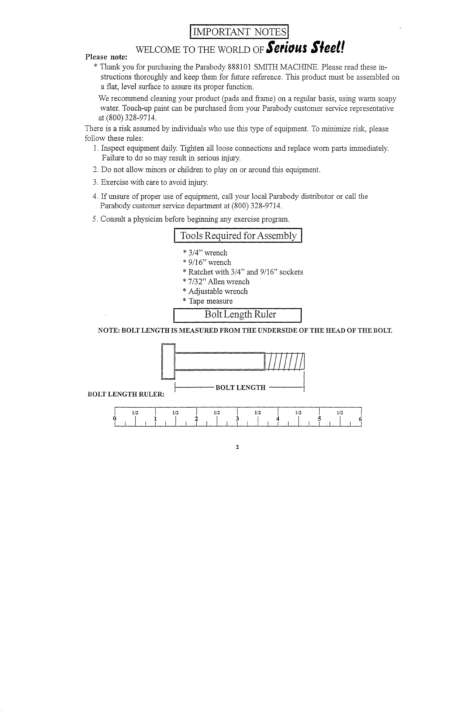
I Tools Required for Assembly [
* 3/4" wrench
*
9/16" wrench
* Ratchet with 3/4" and 9/16" sockets
* 7/32" Allen wrench
*Adjustable wrench
* Tape measure
Bolt Length Ruler
NOTE: BOLT LENGTtt IS MEASURED FROM TI~E UNDERSII)E OF TttE HEAD OF THE BOLT.
.
11///////I
BOLT LENGTH RULER:
1/2 1 1/2 [ 1/2
1
3 4
1/2 [ 1/2
1/2 1
Page 3
1’" 6798103
’2
3
4
~
6
7
"8
,. 6799203
9
6799801
’10
6714901
11
32030o2[
PART
679~103
67985O2
6798402
679~702
6798901
6799601
LOWER CROSS BRACE
SMrrl-IBk~
POD
GLm)EROD BUSH]NO
1" SHAFF COLLAR
~,artT #
12
6692601
13
3102"910
14
3102502
15
3102~01
" 16
2
.2
2
2
4
"20
21
18
19
3105302
3105303
6824601
6695801
3109302
6807101
iizsc~ r~o~
3 x 2- END CAP
"a/2 X3 eC,~r
7/16"HO1 ;]?LUG
9/16"HO1 EPLUG
3 - 1/~ X 1-3/ GL/DE
2 I/2" OD RUBI !RBUMPER
6’
12
8
16
6 ,
zk I
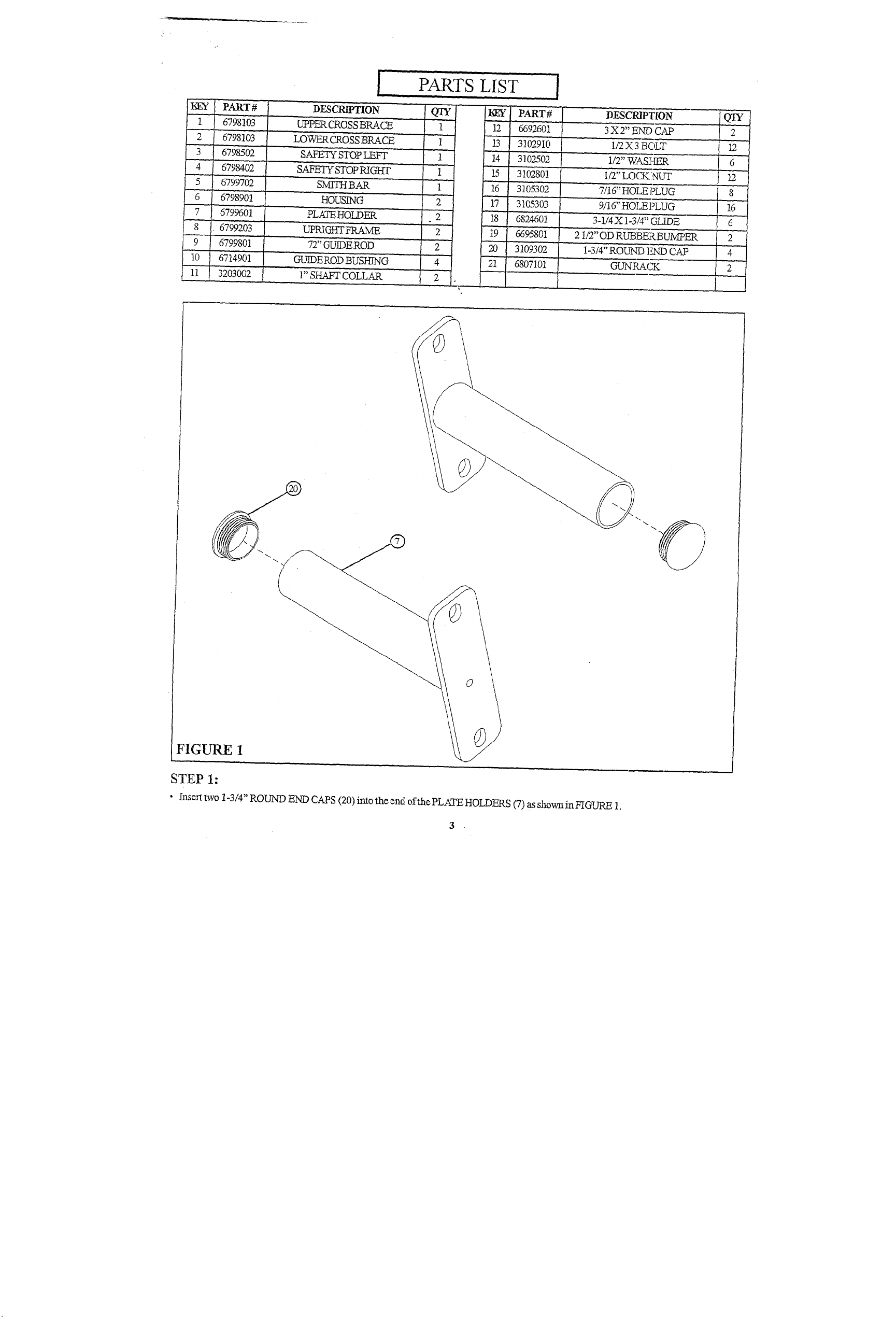
FIGURE 1
STEP 1:
¯ Insert two 1-3/4" ROUND END CAPS (20) into the end of Ne PLATE HOLDERS (7) as shown in FIGURE
Page 4
1/2X3"~
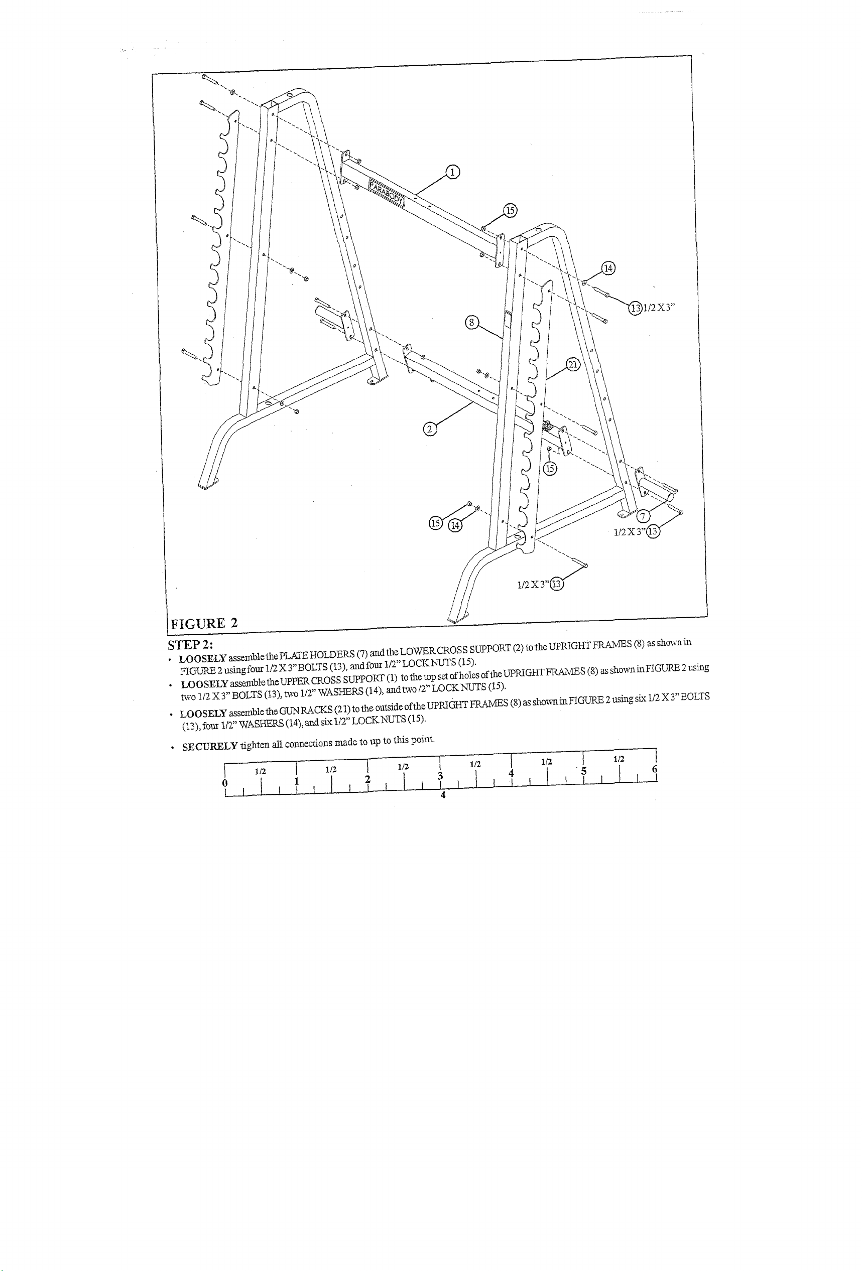
FIGURE 2
STEP 2:
¯
LOOSELY assemblethe PLATEHOLDEP--S (7) andtheLOWERCROSS SUPPORT (2) totheUPRIGIff-f FRAMES (8) as
FIGURE 2 using four 1/2 X 3" BOLTS (13), and four 1/2" LOCKNUTS (15),
LOOSELYassembletheUPPERCROSSSUPPORT(1) tothetopsetofholesoftheupRIGHTFRAMES(8)assh°wninFIGURE2nsing
¯
two 1/2 X3" BOLTS (13), two 1/2" WASHERS (14), andtwo/2" LOCKNUTS (15).
¯ LOOSELY assemble the GUN RACKS (21) to the outside of the UPRIGHT FRAMES (8) as sho~inFIGURE 2 using six 1/2 X 3" BOLTS
(13), fo~ 1/2" WASHERS (14), arid six 1/2" LOCKNUTS (15).
SECURELY tighten all connections made to up to this point.
~ 1/2 I 1/2 i 1/~
Page 5

I
I
I
FIGURE 3
STEP 3:
¯ Insert two 3 X 2" END CAP S (12) into the ends of the UPRIGHT FRAMES (8) as shown in FIGURE
¯ Insert four GUIDE ROD BUSHINGS (10) into the UPRIGHT FRAMES (8) as shown in FIGURE
5
Page 6

FIGURE 4
STEP 4:
¯ Insert one 1-3/4" ROUND END CAP (20) into the end of each HOUSING (6) as shown in FIGURE
¯
Slide one 2-1/2" OD BUMPER (19) over the end of each HOUSING (6) as shown in FIGURE
¯
Insert the shaft of the HOUSINGS (6) into the ends of the SMITH BAR (5) as shown in FIGURE
I 1/2
0
I 1/2
1
I 1/2
2
I 1/2 I 1/2
3
6
4
Page 7

FIGURE 5
;TEP 5:
¯ Hookthe SMITH BAR (5) intothe slots ofthe UPRIGHT FRAM]ES (8).
¯
CAREFULLY slide one GUIDE ROD (9) fltrough the upper hole in the UPRIGHT FRAME (8). Slicte one 1" SHAFT COLLAR (1 l)
the bottom of the GUIDE ROD (9), the CAREFULLY lower the GUIDE ROD (9) through the HOUSING (6) oft the SMITH t3AR (5)
into the bottom hole of the UPRIGHT FRAME (8). Repeat this step on the other side.
¯ Slide the 1" SHAFT COLLARS (11) up the GUIDE RODS (9) to thebushing and SECURELY TIGttTEN.
7
Page 8

FIGURE 6
STEP 6:
Attach six 3-1/4 X 1-3/4" OLI]3ES (18) to the LEFT & RIGHT SAFETY STOPS (3 & 4) as shown in FIGURE 6 using
following steps:
¯
Thoroughly clean all surfaces where the 3-1/4 X 1-3/4" GLIDES (18) are to be attached.
¯
Remove the 3-1/4 X 1-3/4" GLIDES (18) fromthe paper backing and firmly apply them to all shown surfaces.
1/2 [ 1/2
1 2 3
[ 1/2 [ 1/2 [ 1/2 ] 1/2
4 5
8
[
6
Page 9

FIGURE 7
STEP 7:
¯ .Assemble the LEFT & RIGHT SAFETY STOPS (3 & 4) to the UPRIGHT FRAMES (8) as shownin FIGURE
Page 10

FIGURE 8
STEP 8:
¯ Insert sixteen 9/16" CAP PLUGS (17) into the exposed holes inthe UPRIGHT FRAMES (8) as shownin FIGURE
¯ Insert eight 7/16" CAP PLUGS (16) into the exposed holes in the UPPER & LOWER CROSS BRACES (1 & 2) as sho~t in FIGURE
Thank you for purchasing the Parabody 888101 SMITH MACHINE. If unsure of proper use of equipment,
call your local Parabody distributor or call the Parabody customer service department at (800) 328-9714.
10
Page 11

FIGURE 8
STEP 8:
¯ Insert sixteen 9/16" CAP PLUGS (17) into the exposed holes inthe UPRIGHT FRAMES (8) as shownin FIGURE
¯ Insert eight 7/16" CAP PLUGS (16) into the exposed holes in the UPPER & LOWER CROSS BRACES (1 & 2" as sho~a~ in FIGURE
Thank you for purchasing the Parabody 888101 SMffH MACHINE. If unsure ofpropeJ" use of equipment,
ca!l Yo_ur loc.a1 _Pa~abody_~.i~.tributor or call the Parabody customer service department at (800) 328-9714.
10
 Loading...