

Serious Steel
887101 LAT OPTION
Pan # 6802501
I I
ASSEMBLY. INSTRUCTIONS "
1
RmA.sion: 3/23/99
I IMpORTANT".NOTESI
WELCOME TO THE WORLD OF ~t~il~$ ~t~t~!
Please note:
* Thank you for purchasing the Parabody 887101 LAT OPTION. Please read these instruction~
thoroughly and keep them for future reference. This product must be assembled on a flat, lev:
surface to assure its proper function.
We recommend cleaning your product (pads and flame) on a regular basis, using warm soapy
water. Touch-up paint can be purchased from your Parabody customer service representative
at (800) 328-9714.
There is a risk assumed by indix4duals who use this type of equipment. To minimize risk, please
follow these rules:
Inspect equipment daily. Tighten all loose connections and replace worn parts immediately.
1.
Failure to do so may result in serious injury.
2. Do not allow minors or children to play on or around this equipment.
Exercise with care to avoid injury.
3.
4. If unsure of proper use of equipment, call your local Parabody distributor or call the
Parabody customer service department at (800) 328-9714.
5. Consult a physician before be~nning any exercise program.
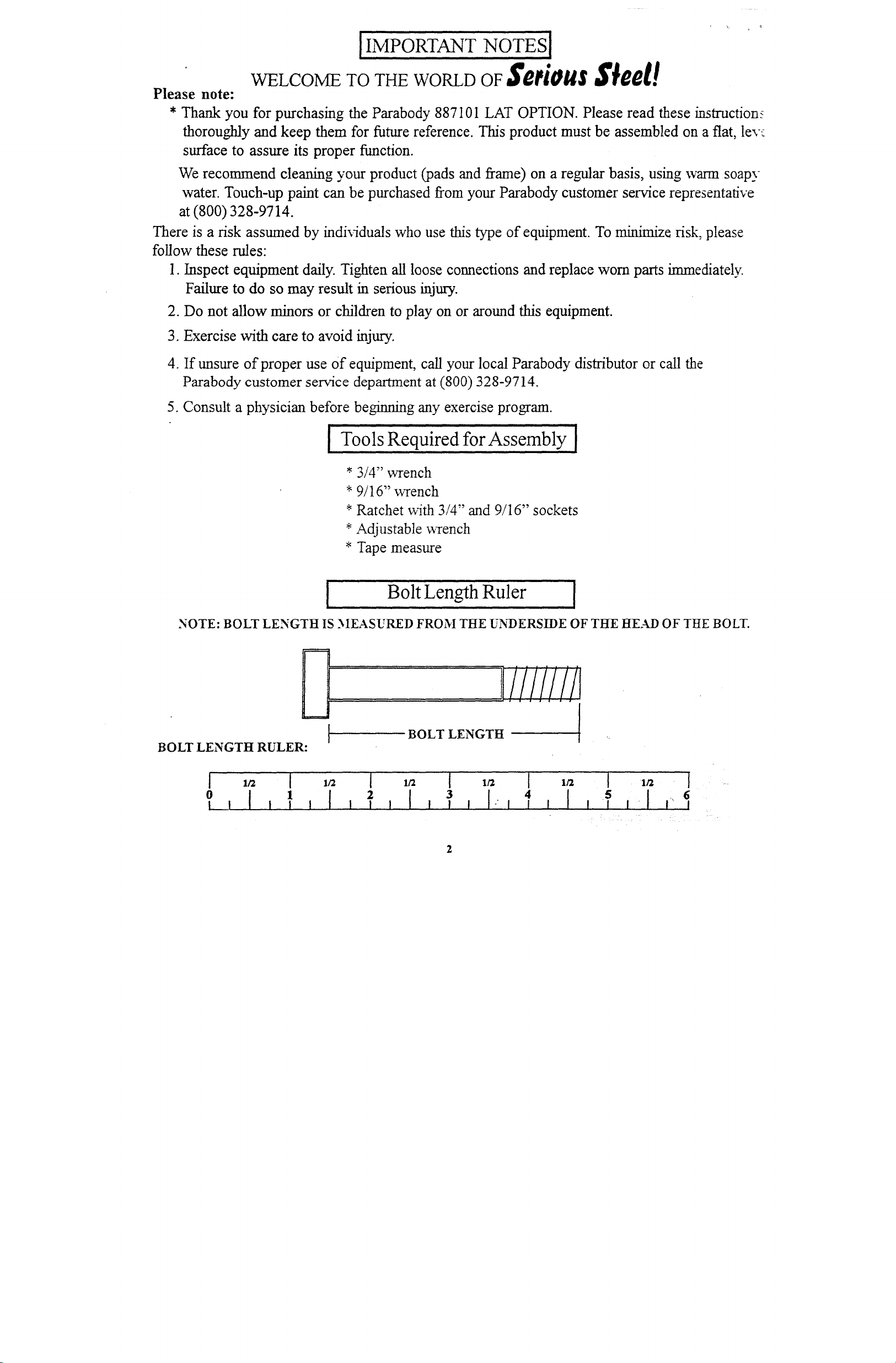
[ Tools Required for Assembly [
*3/4" wrench
*9/16" ~vrench
*Ratchet with 3/4" and 9/16" sockets
*Adjustable wrench
* Tape measure
I
NOTE: BOLT LENGTH IS MEASURED FROM THE UNDERSIDE OF THE HEAD OF THE BOLT.
Bolt Length Ruler [
BOLT LENGTH RULER:
Ol I I I I I
I I
BOLT LENGTH
I 1/2
I I I "I
2
PARTS LIST
KEY
1
2
3
4
5
16
17
18
19
PART#
6800203
~(X)602 ADJ FOOT SUPPOlZT
6800803 PUI I .h’5[HOUSING
6801003
6801102
6759802 ~ARRIAGE
6274402 LOW ROW BAR
6725302 LAT BAR’
3116201
3116101
3103102
6140701
6405201
3116001
6177001
3119301
2-1./2 X 5-1/2" NON-SKID STRIP
DESCRIPTION
UPRIGHT
TOP BOOM
LAT BAR SUPPORT" ’
3-1/2" PUI 1 Fry
4-1/2" PL7 J EY
115-1/4" CABLE
121-3/4" CABLE
3X2"END CAP
1XS" GRIP
1 X 1" t~ J’DE
2" SQ. END CAP
1-1/4" SQ. RUBBER.BUMPER
2-1/2" ROUND END CAP ....
1 ’20
1 22
I 23
1 24
1
I 27
5 28
1 29
1 3O
2 32
4
8 34
2 35
1 36
2
2
’J3’
37
PART # DESC’R1PTION
’623670’i 1-3/4" SQ. :END CAP
6412001 SPRING P ~ SEMBLY
32033’01 VINYLCAP
3/16X I-3N X 5-1/4" PLATE
25
6416601
3102943
3102502
3102801
3102917
3102807
3/4’X 1-112" GLIDE
1/2X3 I/2" BOLT
m" sr~.
1/2" l ),UK.NUT
1/2 28 4" BOLT
3/8" LOWHE
3102501
3/8"L ?CK NIYr
3102922 ’ 3/8X 2-3/4" BOLT
6480301 3/8"Fl.,,~d IE SPACER
3103801 5/16" SNAP HOOK
3102933 3/8 X OLT
3108102 1/4" QUICK LINK
6075906
38’
31029O6 3/8 X
12 i/~ CHAIN
3HTLOCKNUT
SHEK
)LT
!i’ ,’..~’L~.,
~ 7/16" CAP
PLUG
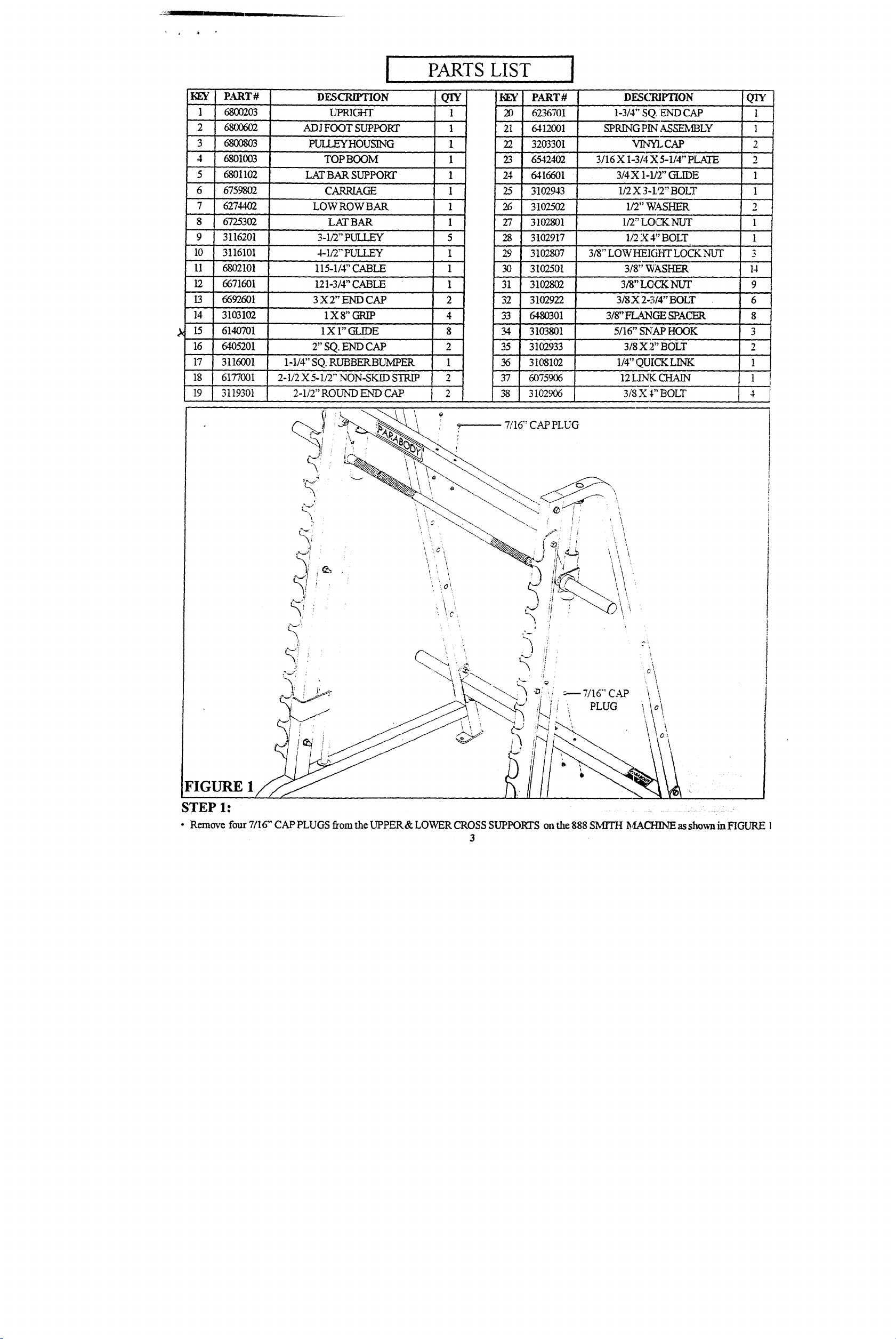
STEP 1:
¯ Remove four 7/16" CAP PLUGS from the UPPER& LOWER CROSS SUPPORTS onthe 888 SMITH MACH/NE as shownin FIGURE 1
3
LOWER CROSS SUPPORT
3/8" LOW HEIGHT LOCK N-U’T ~
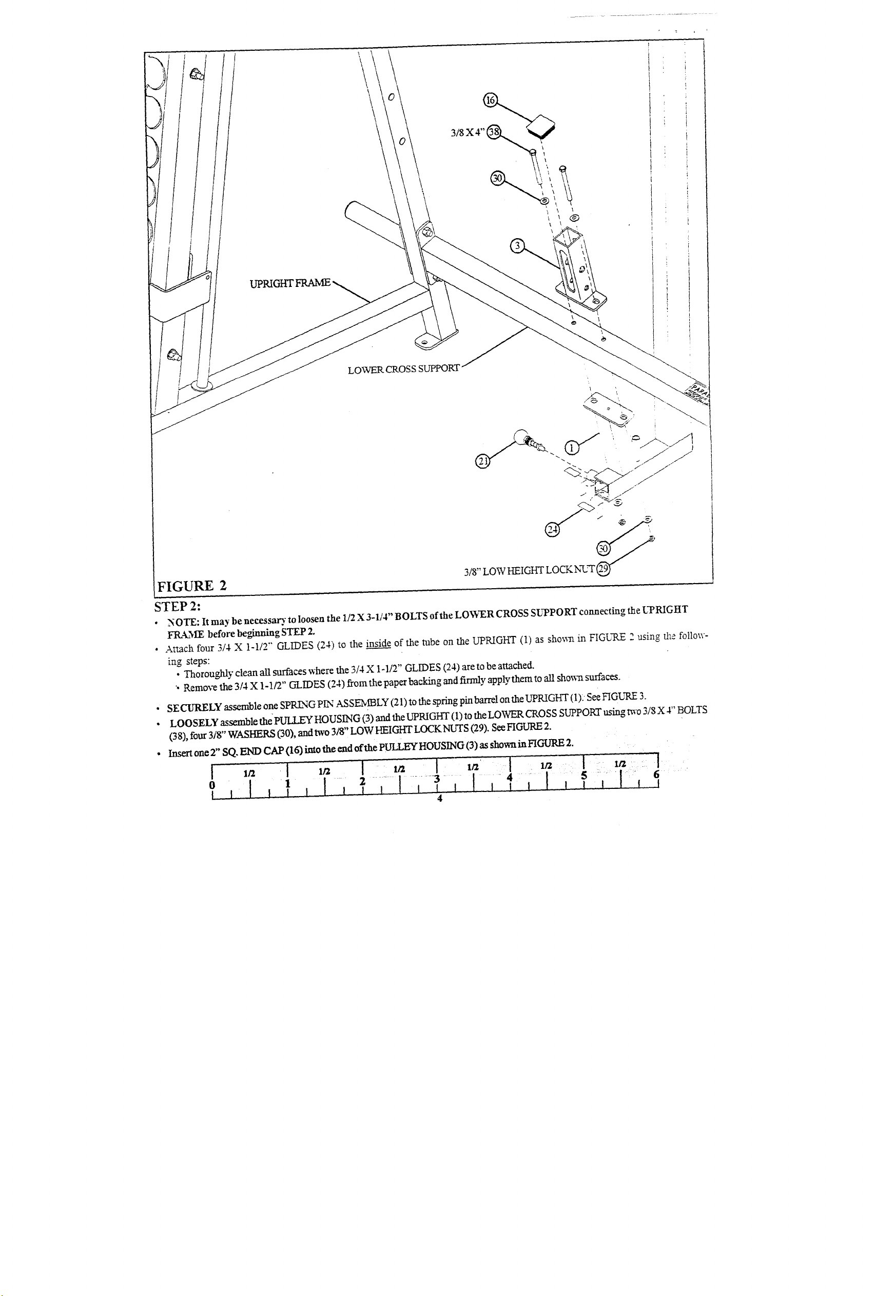
FIGURE 2
STEP 2:
NOTE: It may be necessar.~. to loosen the 1/2 X 3-1/4" BOLTS of the LOWER CROSS SUPPORT connecting the UPRIGHT
¯
FIL~.ME before beginning STEP 2.
¯ Attach four 314 X 1-1/T’ GLIDES (24) to the inside_ of the tube on the UPRIGHT (1) as sho~ in FIGURE 2 using tI~e follow-
~ng steps:
Thoroughly clean all surfaces where the 3/4 X 1-1/2" GLIDES (24) are to be attached.
¯
"- Remo’,~ the 3/4 X 1 - 1/2" GL IDES ( 24 ) from the paper backing and firmly apply them to all sho~aa surfaces.
¯ SE CURELY assemble one SPRLNG P~q AS SENfl3LY (21) to the spring pin barrel on the UPRIGHT (1): See FIGI~q~E
LOOSELY assemble thePU! I EY HOUSING (3) and the UPRIGHT (1) to the LOWER CROSS SUPPORT using m-o 318 X 4" BOLTS
¯
(38), four 3/8" WASHERS (30), and two 3/8" LOW P~IGHT LOCKNUTS (29). See FIGURE
¯
SQ. END CAP (16) into the end of the PULLEY HOUSING (3) as shown in FIGURE Insert one 2"
¯ ..... I-, .....
,,, I,
:,

FIGURE
STEP 3:
¯
Insert two 2-1/2’ ROUND END CAPS (19) into the ends of the .ADJ. FOOT SUPPORT (2) as shown in FIGURE
¯
Insert one I-3/4" ENiD CAP (20) into the end ofthe ADJ. FOOT SUPPORT (2) as shown in FIGURE
¯
Apply m’o 2-1/2 X 5-1/2" NON-SKID STRIPS (18) to the ADJ. FOOT SUPPOKI" (2) as sho~n in FIGL~q.E
¯
Attach four 3/4 X 1-I/2" GLIDES (24) to the outside of the .4~DJ FOOT SUPPORT (2) and four GLIDES to the inside of the
tube on the UPRIGHT (1) as showrt in FIGURE 3 using the follo~ng steps:
¯
Thoroughly clean all surfaces where the 3/4 X 1-112" GLIDES (24) are to be attached.
¯
Remove the 3/4 X I o 1/2" GLIDES (24) from the paper backing and firmly apply them to all show~l srxfaees.
¯ Pull back on the SPRING PIN (21 ) and CAREFIILLY insert the AD I. FOOT SUPPOKr (2) into the UPRIGHT (1) as shown in FIGURE 3.
//
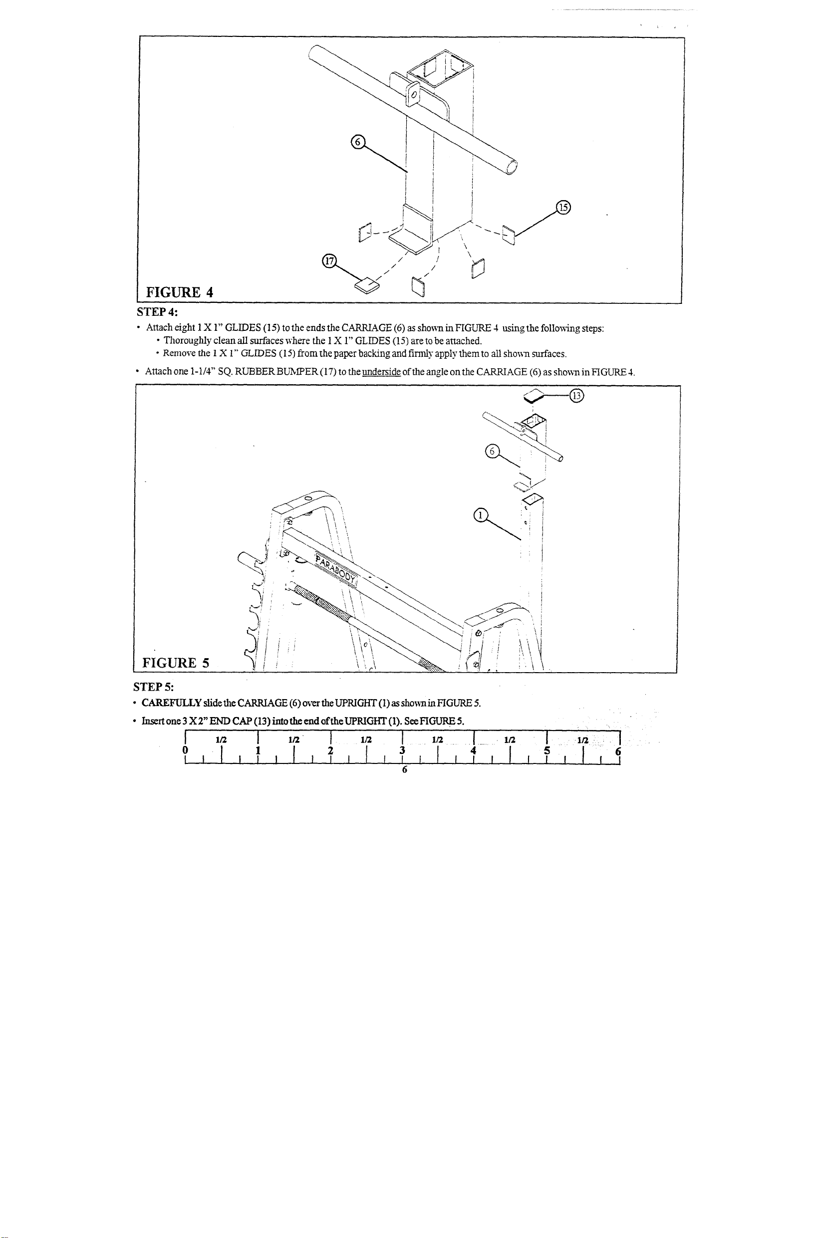
FIGURE 4
STEP 4:
¯ Attach eight 1X 1" GLIDES (15) to the ends the CARRIAGE (6) as sho~l in FIGURE 4 using the follo~4ng steps:
¯ Thorougltly clean Ml surfaces where the 1 X 1" GLIDES (15) are to be attached.
¯
Remove the 1 X 1" GLIDES (15) from the paper backing and firmly apply" them to all sho~-n surfaces.
¯ Attach one 1-1/4" SQ. RUBBER BUN~PER (17) to the underside of the angle on the CAP,~AGE (6) as shown in FIGURE
FIGURE
STEP 5:
¯ CAREFULLY slidethe CARRIAGE (6) over the UPRIGHT (1) as sho,~,min FIGURE
¯ Insert one 3 X 2" END CAP (13) imo the end oft.he UPRIGHT (1). See FICAJRE
0
1
1
I
3 4

FIGURE 6
l/2 X 4"
SUPPORT
STEP 6:
¯ NOTE: It may be necessary to loosen the 1/2 X 3-1/4" BOLTS of the UPPER CROSS SUPPORT connecting the UPRIGITr
FRAME before beginningSTEP 6.
¯ LOOSELY assemble the TOP BOOM (4) to the UPKIGHT (1) using one 1/2 X 4" BOLT (28), one 112 X 3-1/2" BOLT (25),
~VASHERS (26), and one 1/2 LOCK NL-I-S (.,) as sho~t in FIGURE
¯ LOOSELY assemble the TOP BOOM (4) to the UPPER CROSS SUPPORT using t~vo 3/8 X 4" BOLTS (38).~ four 3/8"’ WASHERS
and two 318" LOCK NUTS (31). See FIGURE
¯
Insert one 3 X 2" END CAP (13) imo the ~d of the TOP BOOM (4). See FIGURE
SECURELY tighten all connections made up to this point.
"
97
FIGURE 7
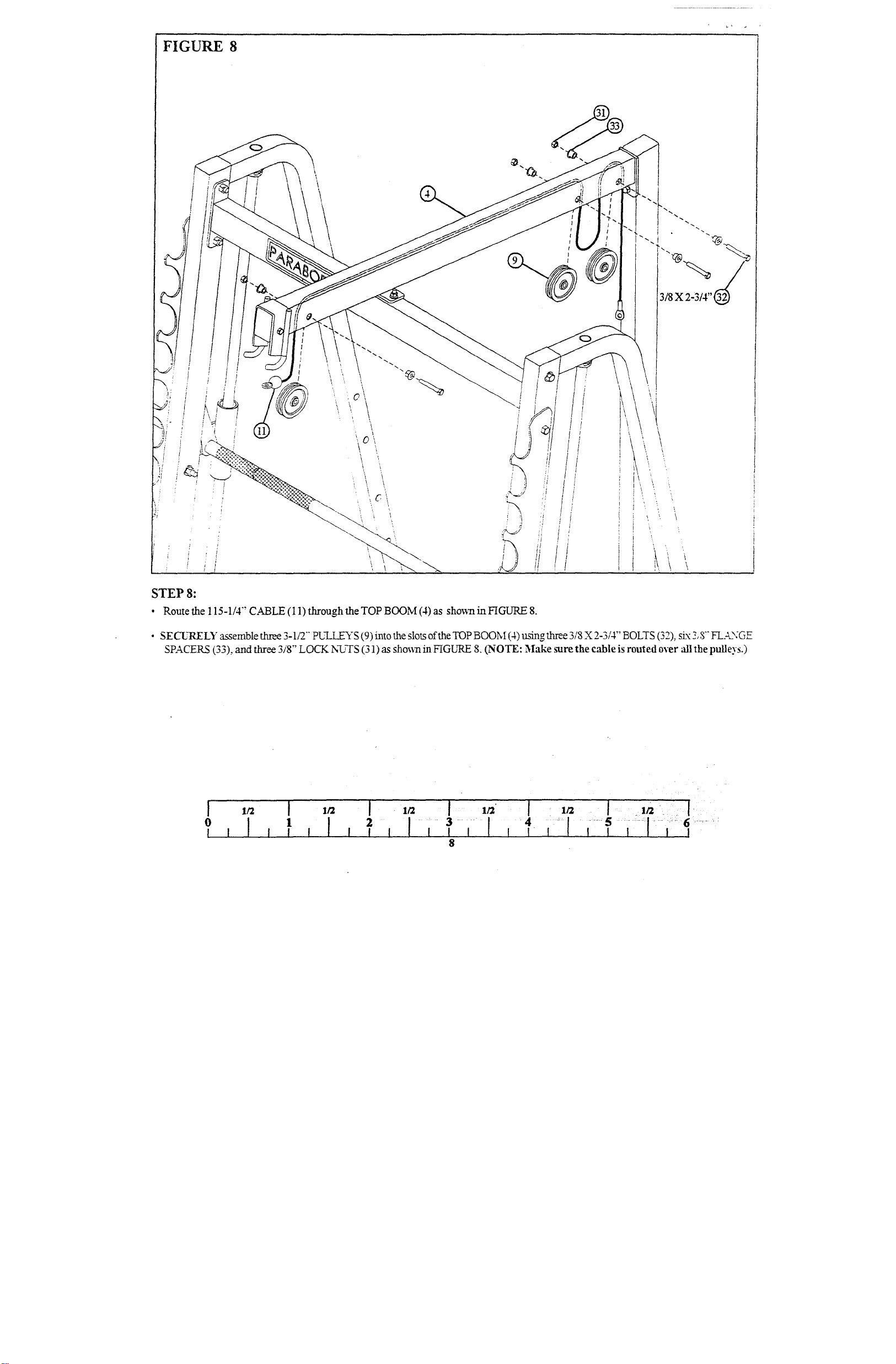
FIGURE 8
3/8 x
STEP 8:
¯ Routethe 115-1/4" CABLE (l l) through the TOP BOOM (4) as sho~vn in FIGURE
¯ SECL’RELY assemble three 3-1/2"" PI]LI EYS (9) into the slots of the TOP BOOM (4) using three 3/8 X 2-3/4" BOLTS (32), six
SPACERS (33), and three 3/8" LOCK N~’TS (31) as sho~.n in FIGLrRE 8. (NOTE: Make sure the cable is routed over "all the pulleys.)
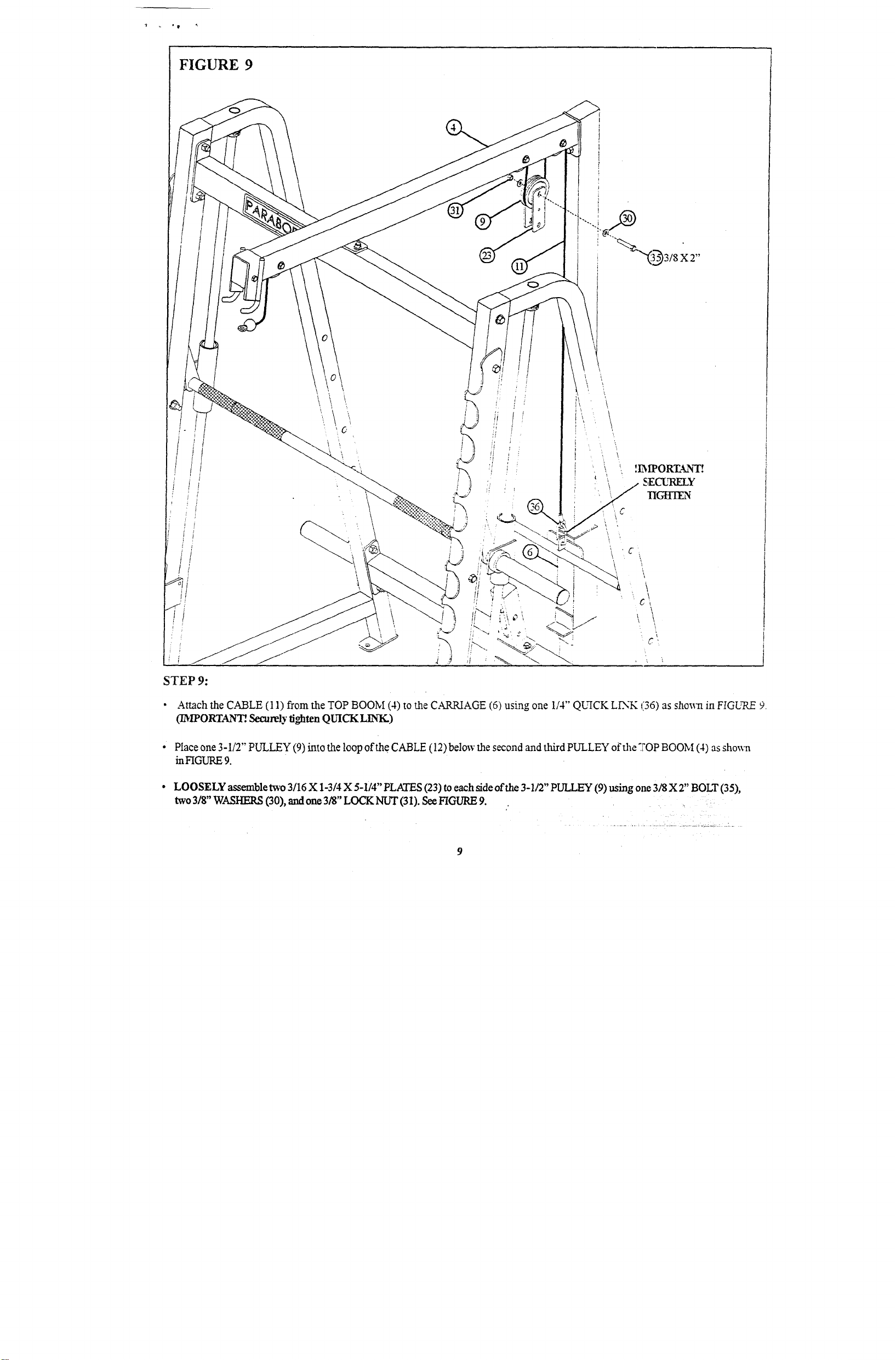
FIGURE 9
STEP 9:
¯
Attach the CABLE (11) from the TOP BOOM (4) to the CARRIAGE (6) using one 1/4" QUICK LINK (36) as shm~al FIGURE 9.
(I/~[PORTAN-~. Secure
¯
Place one 3-1/2" pLrLLEY (9) into the loop of the CABLE (12) below the second and third PULLEY of the ~FOP BOOM (4) as
in FIGURE 9.
LOOSELY assemble two 3/16 X 1-3/4 X 5-1/4" PLATES (23) to each side of the 3-1/2" PULLEY (9) using one 318 X 2" BOLT (35),
two 318" WASI-IERS (30), and one 3/8" LOCK NUT (31). See FIGURE
lighten QUICKLINK.)
b"
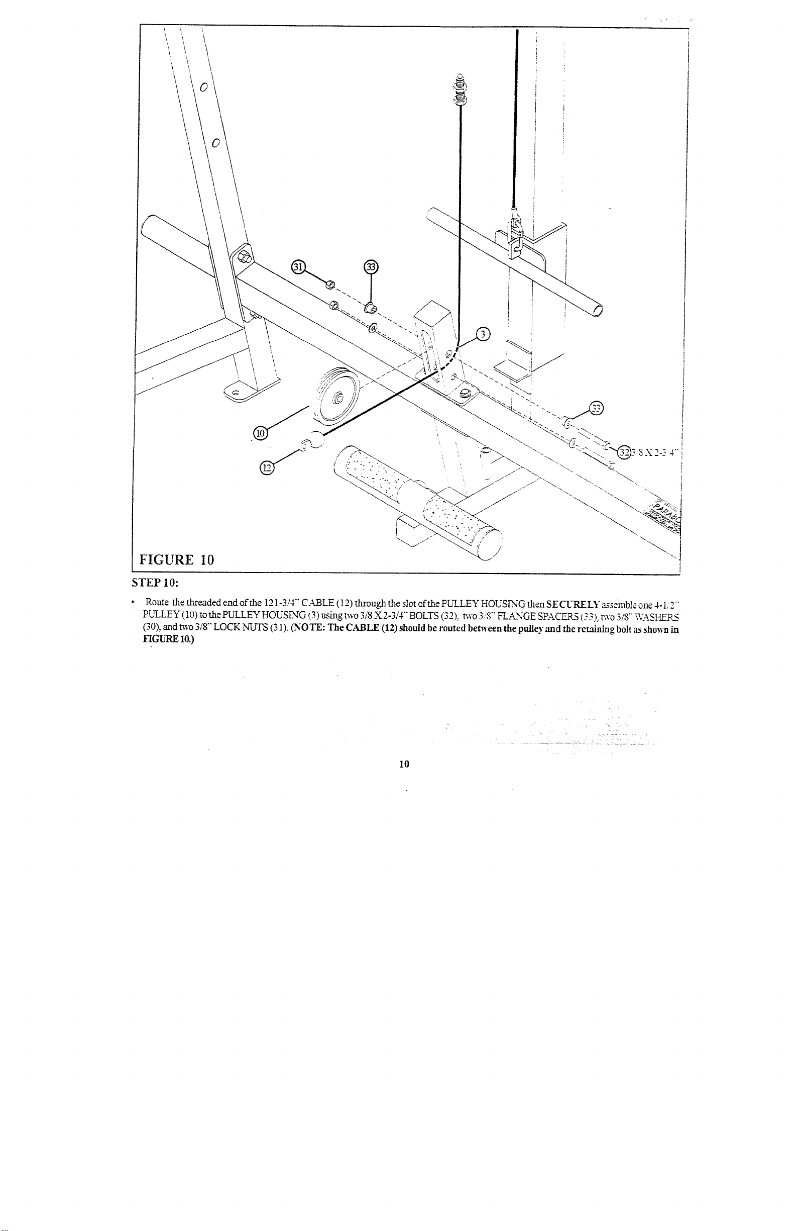
FIGURE 10
STEP 10:
Route the threaded end of the 121-3/4" CABLE (12) through the slot oft.he PULLEY HOUSING then SECURELY assemble one 4-1/2
pLrLLEY (10) to the PU~.I.EY HOUSLNG (3) using t~vo 3/8X 2-3/4"" BOLTS (32), two 3/8"" FLANGE SPACERS (.: 3), two 3/8"" \\:-kSHERS
(30), and two 3/8" LOCK NUTS (31). (NOTE: CABLE (12)should be routed benveen the pulley and the retaining bolt as shown
FIGURE 10.)
10

THREADED END
FIGURE 11 Q/
STEP 11:
Loop the 121-3/4"" CABLE (12) around one 3-1/2" PULLEY (9) as shown in FIGURE
¯
LOOSELY assemble the 3-1/2" PUI JI.EY (9) to the 3/16 X 1-3/4 X 5-1/4" PLATES (23) using one 3/8 X 2" BOLT (35), mo 3/8" V¢.~SI-IERS
(30), and one 3/8" LOCK NUT (31). See FIGLrRE 11.
¯ SECURELY thrend the end of the 121-3/4" CABLE (12) 3/4 of the way into .into the threaded housing on tile UPRIGHT and SF.,-
CURELY tight~j~im rm~_ ....... . ...... ¯ .
¯ SECURELY tightenthe two 3/8 X 2" BOLTS 05) ofthe 3/16 X 1-3/4 X 5-1/4" PLATES (23).
11
¯ ~
/ /i
i!
l
/,,il/
/ I!
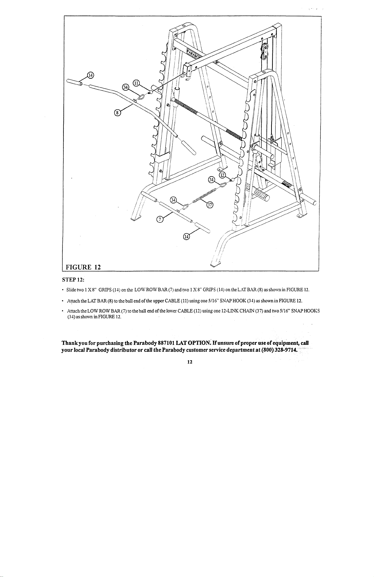
FIGURE 12
STEP 12:
¯ Slide t~vo 1 XS" GRI~PS (14) onthe LOWROWBAR(7) and t~vo 1X 8" GR~S (14) onthe LAT BAR (8) as sho~vnin FIGURE
¯ Attach the LAT BAR (8) to the ball end of the upper CABLE (11) using one 5/16"’ SNAP HOOK (34) as shown in FIGURE
¯ Attach the LOW ROW BAR (7) to the ball end of the lower CABLE (12) using one 12-LINK CHAIN (37) and t~vo 5/16" SNAP
(34) as shosx~ i~ FIGURE 12.
Thank you for purchasing the Parabody 887101 LAT OPTION~.If unsure ofproper use of equipment, call
your local Parabody distributor or call the Parabody customer service department at (800) 328-9714. - .....
12
 Loading...