

Page 1
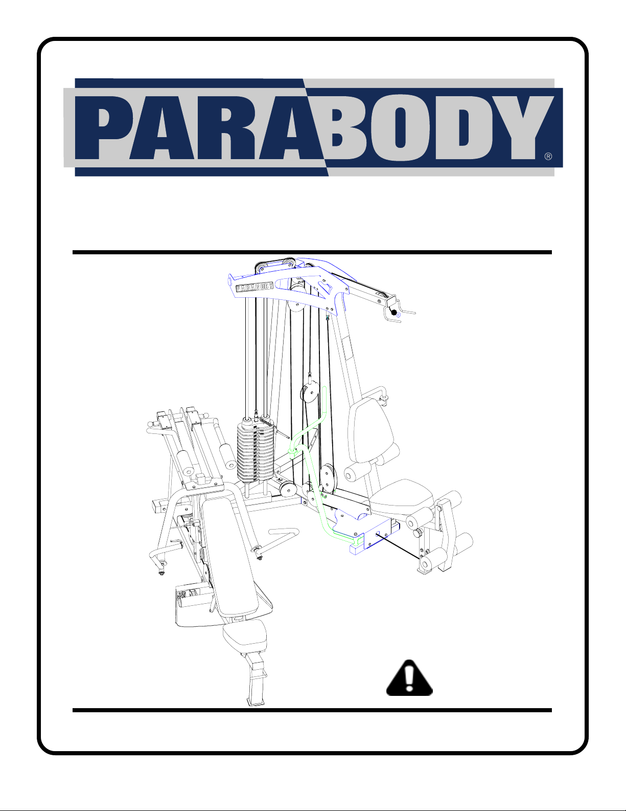
883 SECOND STACK OPTION
FOR 880 GYM SYSTEM
CLASS H
PART # 7168901
REV . C
USER’S GUIDE
1
WARNING:
Read and follow all directions
for each step to insure proper
assembly of this product.
Version: 883102
Revision: 3/08/02
Page 2
j
TABLE OF CONTENTS
Safety Statement.............2
General Notes..................3
Tools Required................3
Parts list..........................4
Assembly Instructions.....5-31
Insert-Registration Card
IMPORTANT SAFETY INFORMATION
THERE IS A RISK ASSUMED BY INDIVIDUALS WHO USE THIS TYPE OF
EQUIPMENT. TO MINIMIZE RISK FOLLOW THESE RULES!
1. Before using, read all the warnings and instructions
on the use of this machine. Use only for intended
exercise. DO NOT modify the machine.
2. Obtain a medical exam before beginning any
exercise program.
3. Keep body and clothing free of all moving objects.
4. Inspect the machine before use. DO NOT use it if it
appears damaged. DO NOT attempt to fix a broken or
ammed machine. Notify your authorized ParaBody
dealer before use and have repairs made by an
authorized service technician.
6. Never pin the weights or prop plate into an elevated
position. DO NOT use the machine if found in this
condition. DO NOT attempt to fix. Notify your
authorized ParaBody dealer.
7. Inspect cables and their connections before using
machine. Pay particular attention to the cable ends.
DO NOT attempt to fix. Notify your authorized
ParaBody dealer before use and have repairs made by
an authorized service technician.
8. Make sure all spring loaded pull pins are fully
engaged in the adjustment position and fully tighten
thumbscrew before use.
5. Be certain that weight pin is completely inserted.
Use only the pin provided by the manufacturer. If
unsure, call your authorized ParaBody dealer.
9. Children must not be allowed near this machine.
Supervise teenagers.
.
NOTE: In a continual effort to improve our products, specifications are subject to change
2001 LifeFitness, a division of Brunswick Corporation. All rights reserved.
©
ParaBody is a trademark of Brunswick Corporation
www.parabody.com
2
Page 3
IMPORTANT NOTES
Please note:
* Thank you for purchasing the ParaBody 880 Second Stack Option. Please read these
instructions thoroughly and keep them for future reference.
* This product must be assembled on a flat, level surface to assure its proper function. DO NOT
securely tighten any frame connections until the entire frame has been assembled, unless
otherwise stated.
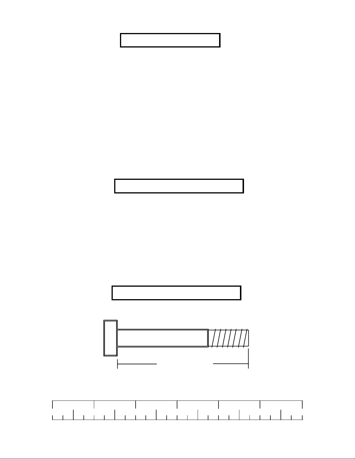
T ools Required for Assembly
* Rubber mallet or hammer
* 3/4” wrench
* 9/16” wrench
* Ratchet with 3/4” and 9/16” sockets
* 7/32” Allen wrench
* Adjustable wrench
* T ape measure
Bolt Length Ruler
NOTE: BOL T LENGTH IS MEASURED FROM THE UNDERSIDE OF THE HEAD OF THE BOLT.
BOLT LENGTH
BOL T LENGTH RULER:
1/2 1/2 1/2 1/2 1/2 1/2
0
1
2
345
3
6
Page 4
PARTS LIST
1
2
3
4
5
6
7
8
9
10
11
12
PART #
7160208
7167908
6523401
7095701
7012102
6957302
7165701
7156101
3116201
6972201
3108002
6978101
DESCRIPTION
ST ACK BASE
LEFT BOOM BRACKET
GUIDE ROD
WEIGHT ST ACK SHAFT
WEIGHT ST ACK SP ACER
HEAD PLA TE
PRESS ST ACK CABLE
LEG CABLE
3-1/2” PULLEY
WEIGHT ST ACK PIN
WEIGHT ST ACK CUSHION
WEIGHT ST ACK LABEL
QTY
1
1
2
1
2
1
1
1
2
1
2
1
KEY
13
14
15
16
17
18
19
20
21
22
23
24
PART #
3102924
3102807
3102906
3102955
3102802
3102501
3102503
6939202
6382301
3221702
3103302
7159801
DESCRIPTION
3/8 X 1-3/4” BOLT
3/8” LOW HEIGHT LOCK NUT
3/8 X 4” BOLT
3/8 X 4-1/4” BOLT
3/8” LOCK NUT
3/8” WASHER
3/4” WASHER
WEIGHT PLA TE
WEIGHT PLA TE BUSHING 10 CT .
E-RING
13/16” SHAFT COLLAR
THREADED HOUSING
QTY
15
KEY
• NOTE: If assembling the SECOND ST ACK OPTION to a completely assembled (including cables) 880
GYM SYSTEM without LEG PRESS OPTION, please r efer to PAGE 5.
3
2
2
2
3
4
2
3
1
2
1
• NOTE: If assembling the SECOND ST ACK OPTION to a completely assembled (including cables) 880
GYM SYSTEM with LEG PRESS OPTION, please refer to PAGE 16.
4
Page 5
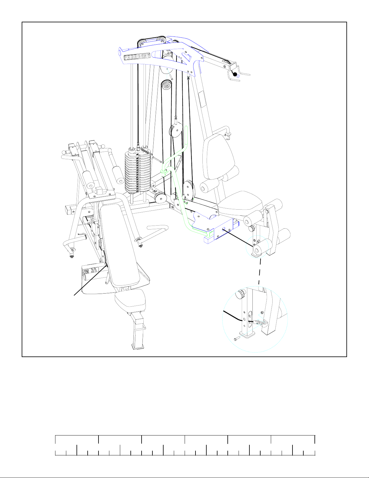
PRESS/LEG
CABLE
FIGURE 1
STEP 1:
• NOTE: Follow these steps if assembling the SECOND STACK OPTION to a completely assembled (including cables)
880 GYM SYSTEM without LEG PRESS OPTION, otherwise please refer to PAGE 4.
• REMOVE the PRESS/LEG CABLE from the 880 GYM SYSTEM . Discard the PRESS/LEG CABLE . See FIGURE 1. (NOTE:
Remove pulleys for ease of removal.)
1/2 1/2 1/2 1/2 1/2 1/2
0
1
2
345
5
6
Page 6
REAR UPRIGHT
3/8 X 4” BOLTS
FIGURE 2
STEP 2:
• Remove the two 3/8 X 4” BOLTS, four 3/8” WASHERS and two 3/8” LOCK NUTS from the REAR UPRIGHT as shown in
FIGURE 2.
FIGURE 3
16 3/8 X 4-1/4”
17
BASE FRAME
3/8 X 4” BOLTS
STEP 3:
• SECURELY assemble the STACK BASE (1) to the BASE FRAME using two 3/8 X 4-1/4” BOLTS (16), two previously removed
3/8 X 4” BOLTS, four 3/8” WASHERS (18), four previously removed 3/8” WASHERS, two 3/8” LOCK NUTS (17) and two
previously removed 3/8” LOCK NUTS as shown in FIGURE 3.
6
1
18
Page 7
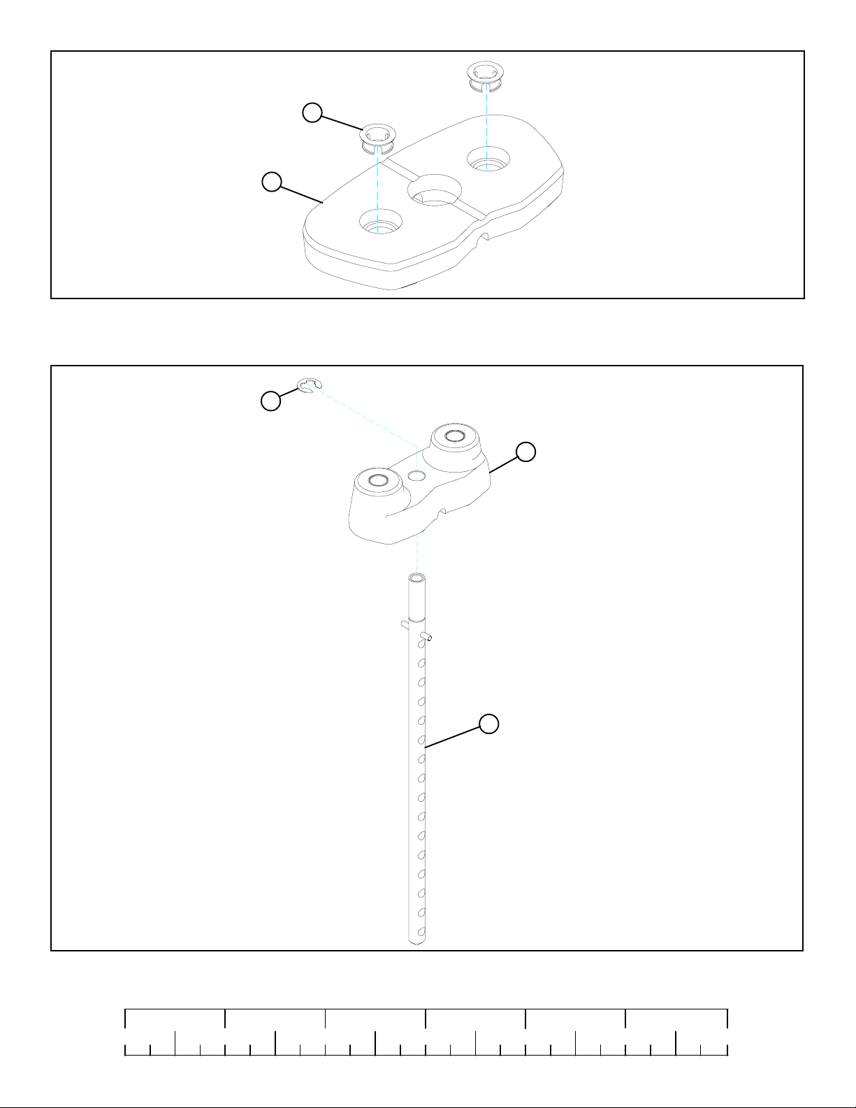
21
20
FIGURE 4
STEP 4:
• Insert two WEIGHT PLATE BUSHINGS (21) into each of the fifteen WEIGHT PLATES (20) as shown in FIGURE 4.
22
6
4
FIGURE 5
STEP 5:
• Slide the WEIGHT PLATE SHAFT (4) thru the hole in the HEAD PLATE (6), and lock in place using one E-RING (22) as shown in
FIGURE 5.
1/2 1/2 1/2 1/2 1/2 1/2
0
1
2
345
7
6
Page 8
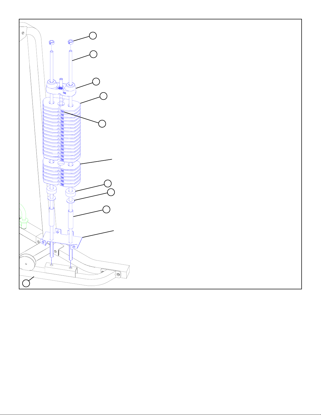
23
3
FIGURE 6
6
20
12
OPTIONAL 50
LB. ADD-ON KIT
11
19
5
880 SHROUD
OPTION ONL Y!
1
STEP 6:
• Insert two GUIDE RODS (3) into the STACK BASE (1) as shown on FIGURE 6. (NOTE: If the 880 SHROUD OPTION was
purchased, place the GUIDE RODS (3) through the BOTTOM SHROUD BRACKET (found in SHROUD OPTION box)
and into the STACK BASE (1) as shown in FIGURE 6.
• (NOTE: Lubricate GUIDE RODS (3) with silicon or teflon spray available at most hardware stores.)
• Slide two WEIGHT STACK SPACERS (5), two 3/4” FLAT WASHERS (19), and two WEIGHT ST ACK CUSHIONS (1 1) down
over the GUIDE RODS (3).
• Using EXTREME CARE slide all fifteen WEIGHT PLATES (20) (NOTE: If 50-LB. ADD-ON KIT was pur chased, slide twenty
WEIGHT PLATES and discard two WEIGHT STACK SPACERS (5), two 3/4” FLAT WASHERS (19) use the 50 LB. ADDON HEAD PLATE and refer to the 50 LB. ADD-ON Kit instructions) down over the GUIDE RODS (3) on to the WEIGHT
STACK CUSHIONS (11). Make sure that the WEIGHT PLATES (20) are all facing as shown.
• Slide the head plate assembly down over the GUIDE RODS (3) onto the weight stack.
• Slide two SHAFT COLLARS (23) over the GUIDE RODS (3) as shown in FIGURE 6.
• Apply WEIGHT ST ACK LABELS (12) to WEIGHT PLATES (20) and HEAD PLA TE (6) as shown in FIGURE 6. Begin with number
one at the HEAD PLATE (6) with larger numbers in consecutive order towards bottom of weight stack.
8
Page 9

FIGURE 7
BOOM PLA TE
3”NYLON SPACER
FRAME
REAR UPRIGHT
STEP 7:
• CAREFULLY remove the BOOM PLA TE from the the REAR UPRIGHT and the FRAME as shown in FIGURE 7. Discard the BOOM
PLATE.
2”
NYLON
SP ACER
FIGURE 8
FRAME
2
2”NYLON
SP ACER
BOOM BRACKET
3
REAR
UPRIGHT
STEP 8:
• Swing the GUIDE RODS (3) into the guide rod bushings in the LEFT BOOM BRACKET (2) as shown in FIGURE 8.
• SECURELY assemble the LEFT BOOM BRACKET (2) and the BOOM BRACKET to the REAR UPRIGHT and the FRAME using
the previously removed bolts, nylon spacers, washers and lock nuts as shown in FIGURE 8.(NOTE: The 2” NYLON SP ACERS go
on the LEFT BOOM BRACKET only.)
1/2 1/2 1/2 1/2 1/2 1/2
0
1
2
345
9
6
Page 10
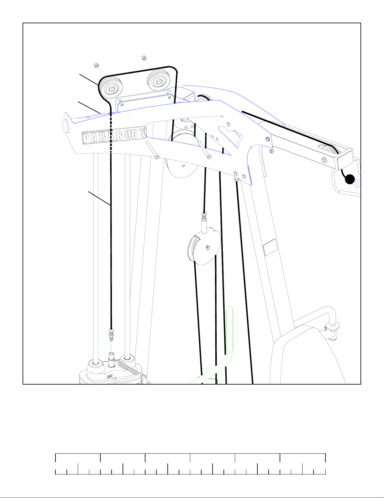
PULLEY
BOOM BRACKET
WEIGHT
ST ACK
CABLE
FIGURE 9
STEP 9:
• Unscrew the threaded ends of the WEIGHT STACK CABLE from the WEIGHT STACK SHAFT and remove the two PULLEYS
from the BOOM BRACKET . See FIGURE 9.
1/2 1/2 1/2 1/2 1/2 1/2
0
1
2
345
10
6
Page 11

FIGURE 10
9
14
WEIGHT
ST ACK
CABLE
2
13 3/8 X 1-3/4”
6
10
STEP 10:
• Assemble two 3-1/2” PULLEYS (9) to the LEFT BOOM BRACKET (2) using two 3/8 X 1-3/4” BOLTS (13) and two 3/8”
LOW HEIGHT LOCK NUTS (14) as shown in FIGURE 10.
• Route the WEIGHT STACK CABLE around the pulleys in the LEFT BOOM BRACKET (2) as shown in FIGURE 10. (NOTE:
Make sure the cable runs in the grooves of the pulleys.)
• Assemble the WEIGHT STACK PIN (10) to the HEAD PLATE (6) as shown in FIGURE 10.
• Screw the long threaded end of the WEIGHT STACK CABLE into the end of the HEAD PLATE (6) .See FIGURE 10.
11
Page 12

7
FIGURE 11
STEP 10:
• Route the new PRESS STACK CABLE (7) thru the PRESS STATION as shown. (NOTE: Remove pulleys for ease of installa-
tion.)
1/2 1/2 1/2 1/2 1/2 1/2
0
1
2
345
12
6
Page 13

7
FIGURE 12
STEP 12:
• Route the new PRESS STACK CABLE (7) thru the PEC STATION as shown. (NOTE: Remove pulleys for ease of installation.)
Slide GUIDE RODS up just enough to get the cable end thru. Push GUIDE RODS down when finished.
STEP 13:
• Route the new PRESS ST ACK CABLE (7)
around the pulleys in the BOOM BRACKET
using the existing bolts as shown in
FIGURE 13. (NOTE: Make sure the cable
runs in the grooves of the pulleys.)
• Screw the threaded end of the PRESS STACK
CABLE (7) into the end of the HEAD
PLATE. See FIGURE 13.
FIGURE 13
BOOM
BRACKET
7
HEAD
PLA TE
13
Page 14

8
PULLEY PLA TES
BASE
FRAME
PEDEST AL
8
24
13 3/8 X 1-3/4”
17
1
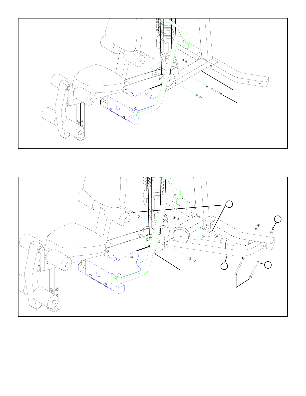
FIGURE 14
STEP 14:
• Assemble the LEG CABLE (8) to the PEDESTAL and route the LEG CABLE (8) thru the BASE FRAME as shown in FIGURE 14.
(NOTE: Remove pulleys for ease of installation.)
• Route the LEG CABLE (8) around the 3-1/2” PULLEY on the PULLEY PLATES using one existing 3/8 X 1-3/4” BOLT and one
existing 3/8” LOCK NUT. See FIGURE 14.
• Securely assemble the threaded end of the LEG CABLE (8) to the THREADED HOUSING (24) then assemble the THREADED
HOUSING (24) to the bracket on the ST ACK BASE (1) using one 3/8 X 1-3/4” BOLT (13) and one 3/8” LOCK NUT (17) as shown
in FIGURE 14.
1/2 1/2 1/2 1/2 1/2 1/2
0
1
2
345
6
14
Page 15

FIGURE 15
23
TIGHTEN!
3
6
ADJUSTMENT
20
ADJUSTMENT
STEP 15:
• SECURELY tighten all loose frame connections.
• Slide the SHAFT COLLARS (23) to the top of the GUIDE RODS (3) and tighten set screws as shown in FIGURE 15.
• Adjustments can be made in the above locations to set the correct amount of tension in the cables. (NOTE: FLOATING PULLEYS
should rest against the stops.)
• If upon completion of assembly, the HEAD PLATE (6) does not sit on top of the first WEIGHT PLATE (20), push the HEAD
PLATE (6) down, insert the WEIGHT STACK PIN (10) and perform several repetitions. This will relax the cable system and
prevent the HEAD PLATE (6) from lifting up. See FIGURE 15.
• For maximum performance, the HEAD PLATE (6) should just barely sit on the top WEIGHT PLATE (20).
• NOTE: After making adjustments make sure all jam nuts are SECURELY TIGHTENED!
• This completes the assembly of the 880 SECOND STACK OPTION. If the 880 SHROUD OPTION was purchased refer to
the 880 SHROUD KIT assembly instructions.
Thank you for purchasing the ParaBody 880 Gym System. If unsure of proper use of equipment, call
your local ParaBody distributor or call the ParaBody customer service department at (800) 328-9714
15
Page 16

PRESS/LEG
CABLE
FIGURE 1
STEP 1:
• NOTE: Follow these steps if assembling the SECOND STACK OPTION to a completely assembled (including cables)
880 GYM SYSTEM with LEG PRESS OPTION (already assembled to the 880), otherwise please refer to PAGE 5.
• REMOVE the PRESS/LEG CABLE as shown in FIGURE 1. Discard the PRESS/LEG CABLE. (NOTE: Remove pulleys for ease of
removal.)
16
Page 17

FIGURE 2
SHORT LEG PRESS CABLE
THREADED HOUSING
STEP 2:
• Carefully remove and discard the SHORT LEG PRESS CABLE from the LEG PRESS as shown in FIGURE 2.
FIGURE 3
3/8 X 4-1/4”
BOL TS
REAR
UPRIGHT
STEP 3:
• Remove the two 3/8 X 4-1/4” BOLTS, two 3/8 X 3-3/4” BOLTS, eight 3/8” WASHERS, PULLEY BRACKET and four 3/8” LOCK
NUTS from the REAR UPRIGHT and the BASE FRAME as shown in FIGURE 3.
17
PULLEY BRACKET
3/8 X 3-3/4” BOLTS
Page 18

FIGURE 4
3/8 X 4-1/4” BOLTS
BASE FRAME
STEP 4:
• SECURELY assemble the STACK BASE (1) to the BASE FRAME using two 3/8 X 4” BOL TS (15), two previously removed 3/8 X
4-1/4” BOLTS, eight previously removed 3/8” WASHERS and four previously removed 3/8” LOCK NUTS as shown in FIGURE 4.
1
3/8 X 4” 15
FIGURE 5
SHORT LEG PRESS
CABLE
STEP 5:
• Remove the SHORT LEG PRESS CABLE from the PULLEY PLATES and the PULLEY BRACKET as shown in FIGURE 5.
18
Page 19

BOOM
BRACKET
SHORT LEG
PRESS CABLE
FRAME
FIGURE 6
STEP 6:
• Remove the rest of the SHORT LEG PRESS CABLE from the FRAME as shown in FIGURE 6. (NOTE: Remove pulleys for
ease of installation.)
19
Page 20

PULLEY
BRACKET
PEC ST A TION P AD
3/8 X 3”
FRAME
FIGURE 7
STEP 7:
• Remove the PULLEY BRACKET, the PEC STATION PAD and two 3/8 X 3” BOLTS from the FRAME. Discard the PULLEY
BRACKET . See FIGURE 7.
PEC ST A TION P AD
3/8 X 3”
18
FRAME
FIGURE 8
STEP 8:
• SECURELY assemble the PEC STATION PAD to the FRAME using two previously removed 3/8 X 3” BOLTS and two 3/8”
WASHERS (18). See FIGURE 8.
1/2 1/2 1/2 1/2 1/2 1/2
0
1
2
345
6
20
Page 21

21
20
FIGURE 9
STEP 9:
• Insert two WEIGHT PLATE BUSHINGS (21) into each of the fifteen WEIGHT PLATES (20) as shown in FIGURE 9.
22
6
4
FIGURE 10
STEP 10:
• Slide the WEIGHT PLATE SHAFT (4) thru the hole in the HEAD PLATE (6), and lock in place using one E-RING (22) as shown in
FIGURE 10.
21
Page 22

23
3
FIGURE 11
6
20
12
OPTIONAL 50
LB. ADD-ON KIT
11
19
5
880 SHROUD
OPTION ONL Y!
1
STEP 11:
• Insert two GUIDE RODS (3) into the ST ACK BASE (1) as shown on FIGURE 11. (NOTE: If the 880 SHROUD OPTION was
purchased, place the GUIDE RODS (3) through the BOTTOM SHROUD BRACKET (found in SHROUD OPTION box)
and into the STACK BASE (1) as shown in FIGURE 11.
• (NOTE: Lubricate GUIDE RODS (3) with silicon or teflon spray available at most hardware stores.)
• Slide two WEIGHT STACK SPACERS (5), two 3/4” FLAT WASHERS (19), and two WEIGHT ST ACK CUSHIONS (1 1) down
over the GUIDE RODS (3).
• Using EXTREME CARE slide all fifteen WEIGHT PLATES (20) (NOTE: If 50-LB. ADD-ON KIT was pur chased, slide twenty
WEIGHT PLATES and discard two WEIGHT STACK SPACERS (5), two 3/4” FLAT WASHERS (19) use the 50 LB. ADDON HEAD PLATE and refer to the 50 LB. ADD-ON Kit instructions) down over the GUIDE RODS (3) on to the WEIGHT
STACK CUSHIONS (11). Make sure that the WEIGHT PLATES (20) are all facing as shown.
• Slide the head plate assembly down over the GUIDE RODS (3) onto the weight stack.
• Slide two SHAFT COLLARS (23) over the GUIDE RODS (3) as shown in FIGURE 11.
• Apply WEIGHT STACK LABELS (12) to WEIGHT PLATES (20) and HEAD PLATE (6) as shown in FIGURE 11. Begin with
number one at the HEAD PLATE (6) with larger numbers in consecutive order towards bottom of weight stack.
22
Page 23

FIGURE 12
BOOM PLA TE
3”NYLON SPACER
FRAME
REAR UPRIGHT
STEP 12:
• CAREFULLY remove the BOOM PLA TE (10) from the the REAR UPRIGHT and the FRAME as shown in FIGURE 12. Discard the
BOOM PLA TE.
2”
NYLON
SP ACER
FIGURE 13
FRAME
2
2”NYLON
SP ACER
BOOM BRACKET
3
REAR
UPRIGHT
STEP 13:
• Swing the GUIDE RODS (3) into the guide rod bushings in the LEFT BOOM BRACKET (2) as shown in FIGURE 13.
• SECURELY assemble the LEFT BOOM BRACKET (2) and the BOOM BRACKET to the REAR UPRIGHT and the FRAME using
the previously removed bolts, nylon spacers, washers and lock nuts as shown in FIGURE 13. (NOTE: The 2” NYLON SPACERS
go on the LEFT BOOM BRACKET only.)
1/2 1/2 1/2 1/2 1/2 1/2
0
1
2
345
23
6
Page 24

PULLEY
BOOM BRACKET
WEIGHT
ST ACK
CABLE
FIGURE 14
STEP 14:
• Unscrew the threaded ends of the WEIGHT STACK CABLE from the WEIGHT STACK SHAFT and remove the two PULLEYS
from the BOOM BRACKET. See FIGURE 14.
24
Page 25

FIGURE 15
9
14
WEIGHT
ST ACK
CABLE
2
13 3/8 X 1-3/4”
6
10
STEP 15:
• Assemble two 3-1/2” PULLEYS (9) to the LEFT BOOM BRACKET (2) using two 3/8 X 1-3/4” BOLTS (13) and two 3/8”
LOW HEIGHT LOCK NUTS (14) as shown in FIGURE 15.
• Route the WEIGHT STACK CABLE around the pulleys in the LEFT BOOM BRACKET (2) as shown in FIGURE 15. (NOTE:
Make sure the cable runs in the grooves of the pulleys.)
• Assemble the WEIGHT STACK PIN (10) to the HEAD PLATE (6) as shown in FIGURE 15.
• Screw the long threaded end of the WEIGHT STACK CABLE into the end of the HEAD PLATE (6) .See FIGURE 15.
1/2 1/2 1/2 1/2 1/2 1/2
0
1
2
345
25
6
Page 26

PULLEY
LA T CABLE
FIGURE 16
STEP 16:
• Route the previously removed original LAT CABLE through the FRAME (1) and assemble one 3-1/2” PULLEY to the PULLEY
PLATES using one existing 3/8 X 1-3/4” BOLT and one exsisting 3/8” LOCK NUT. See FIGURE 16.
PULLEY
PLATES
FIGURE 17
24
LA T CABLE
STEP 17:
• Securely assemble the LAT CABLE to the THREADED HOUSING (24) then assemble the THREADED HOUSING (24) to the
BOOM BRACKET using one previously removed 3/8 X 3-3/4” BOLT, two previously removed 3/8 X 1” SPACERS and one previously removed 3/8” LOCK NUT as shown in FIGURE 17.
26
Page 27

7
FIGURE 18
STEP 18:
• Route the new PRESS STACK CABLE (7) thru the PRESS STATION as shown. (NOTE: Remove pulleys for ease of installa-
tion.)
1/2 1/2 1/2 1/2 1/2 1/2
0
1
2
345
27
6
Page 28

7
FIGURE 19
STEP 19:
• Route the new PRESS STACK CABLE (7) thru the REAR UPRIGHT as shown. (NOTE: Remove pulleys for ease of installa-
tion.) Slide GUIDE RODS up just enough to get the cable end thru. Push GUIDE RODS down when finished.
STEP 20:
• Route the new PRESS ST ACK CABLE (7)
around the pulleys in the BOOM BRACKET
using the existing bolts as shown in
FIGURE 20. (NOTE: Make sure the cable
runs in the grooves of the pulleys.)
• Screw the threaded end of the PRESS STACK
CABLE (7) into the end of the HEAD
PLATE. See FIGURE 20.
FIGURE 20
BOOM
BRACKET
7
HEAD
PLA TE
28
Page 29

PULLEY PLATES
BASE
FRAME
LONG LEG
PRESS CABLE
LONG LEG
PRESS CABLE
PULLEY
1
3/8 X 1-3/4”
FIGURE 21
STEP 21:
• Assemble the LONG LEG PRESS CABLE (from the 883 LEG PRESS OPTION box) to the PEDESTAL and route the LONG LEG
PRESS CABLE thru the BASE FRAME as shown in FIGURE 21. (NOTE: Remove pulleys for ease of installation.)
• Route the LONG LEG PRESS CABLE around the 3-1/2” PULLEY on the PULLEY PLATES using one existing 3/8 X 1-3/4” BOL T
and one existing 3/8” LOCK NUT. See FIGURE 21.
• Route the LONG LEG PRESS CABLE around one previously removed 3-1/2” PULLEY and assemble to the bracket on the BASE
FRAME using one existing 3/8 X 1-3/4” BOLT and one existing 3/8” LOCK NUT. See FIGURE 21.
1/2 1/2 1/2 1/2 1/2 1/2
0
1
2
345
29
6
Page 30

FIGURE 22
LONG LEG PRESS CABLE
THREADED HOUSING
STEP 22:
• Carefully route the LONG LEG PRESS CABLE thru the LEG PRESS as shown in FIGURE 22 and assemble the LONG LEG PRESS
CABLE to the existing THREADED HOUSING.
CABLE ROUTING DIAGRAM
30
Page 31

FIGURE 23
23
TIGHTEN!
3
6
ADJUSTMENT
20
ADJUSTMENT
STEP 23:
• SECURELY tighten all loose frame connections.
• Slide the SHAFT COLLARS (23) to the top of the GUIDE RODS (3) and tighten set screws as shown in FIGURE 23.
• Adjustments can be made in the above locations to set the correct amount of tension in the cables. (NOTE: FLOATING PULLEYS
should rest against the stops.)
• If upon completion of assembly, the HEAD PLATE (6) does not sit on top of the first WEIGHT PLATE (20), push the HEAD
PLATE (6) down, insert the WEIGHT STACK PIN (10) and perform several repetitions. This will relax the cable system and
prevent the HEAD PLATE (6) from lifting up. See FIGURE 23.
• For maximum performance, the HEAD PLATE (6) should just barely sit on the top WEIGHT PLATE (20).
• NOTE: After making adjustments make sure all jam nuts are SECURELY TIGHTENED!
• This completes the assembly of the 880 SECOND STACK OPTION. If the 880 SHROUD OPTION was purchased refer to
the 880 SHROUD KIT assembly instructions.
Thank you for purchasing the ParaBody 880 Gym System. If unsure of proper use of equipment, call
your local ParaBody distributor or call the ParaBody customer service department at (800) 328-9714
31
 Loading...