

Page 1
Serious Steel
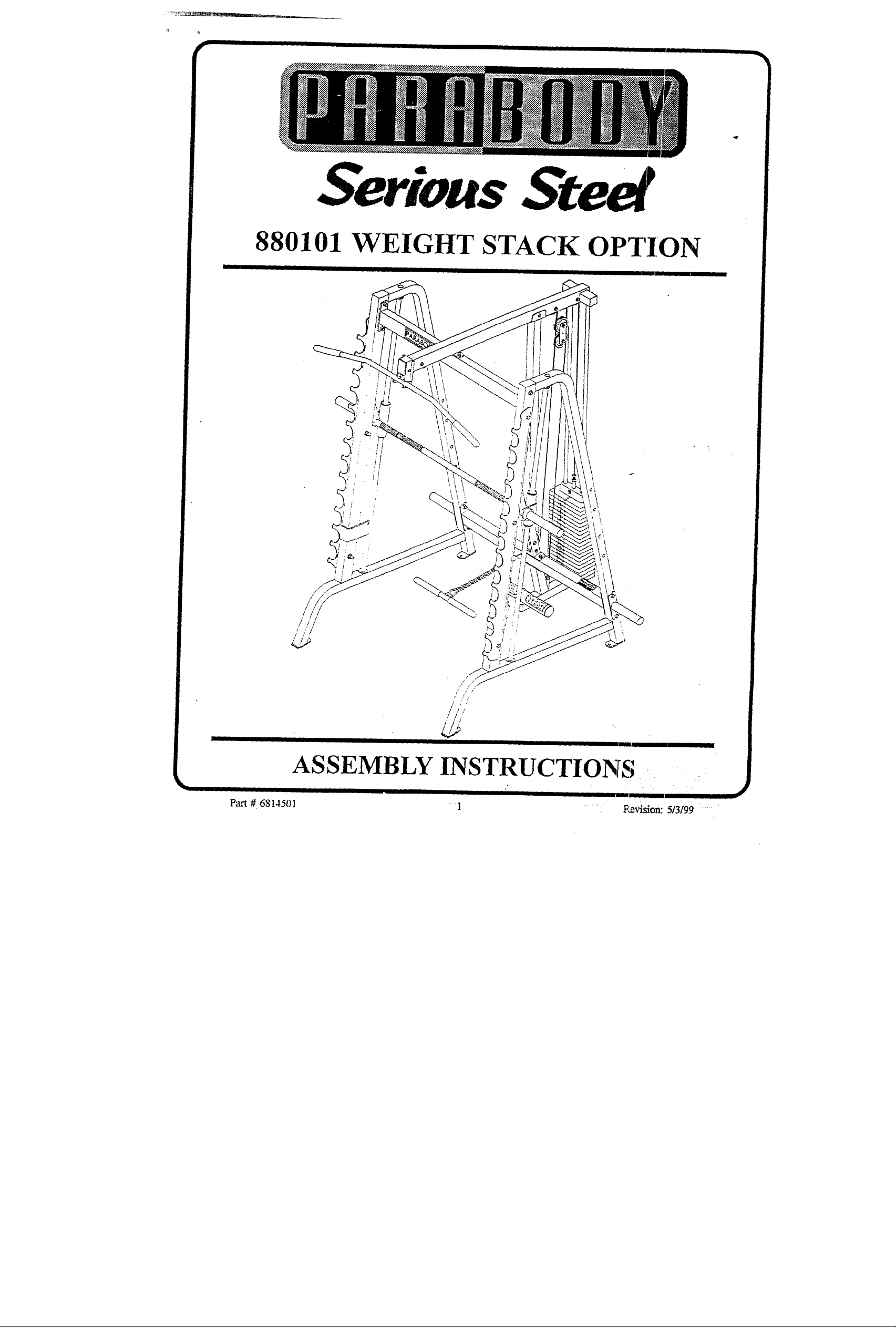
880101 WEIGHT STACK OPTION
ASSEMBLY INSTRUCTIONS
Part #. 6814501
Page 2
I IMPOtLTANT NO~ES
I
~.
WELCOME TO THE WORLD OF St~t/I~$ ~}tt~t~l#
Please note:
* Thank you for purchasing the Parabody 880101 WEIGHT STACK OPTION. Please read
these instructions thoroughly and keep them for future reference. This product must be, assembled on a fiat, level surface to assure its proper function.
We recommend cleaning your product (pads and frame) on a regular basis, using warm soapy
water. Touch-up paint can be purchased from your Parabody customer service representative
at (800) 328-9714.
There is a risk assumed by individuals who use this type of equipment. To m/nimize risk, please
follow these rules:
1. Inspect equipment daily. Tighten all loose connections and replace worn parts immediately.
Failure to do so may result in serious injury.
2. Do not allow minors or children to play on or around tlzis equipment.
3. Exercise with care to avoid injury.
4. If unsure of proper use of equipment, call your local Parabody distributor or call the
Parabody customer service department at (800) 328-971D.
5. Consult a physician before beginning any exercise program.
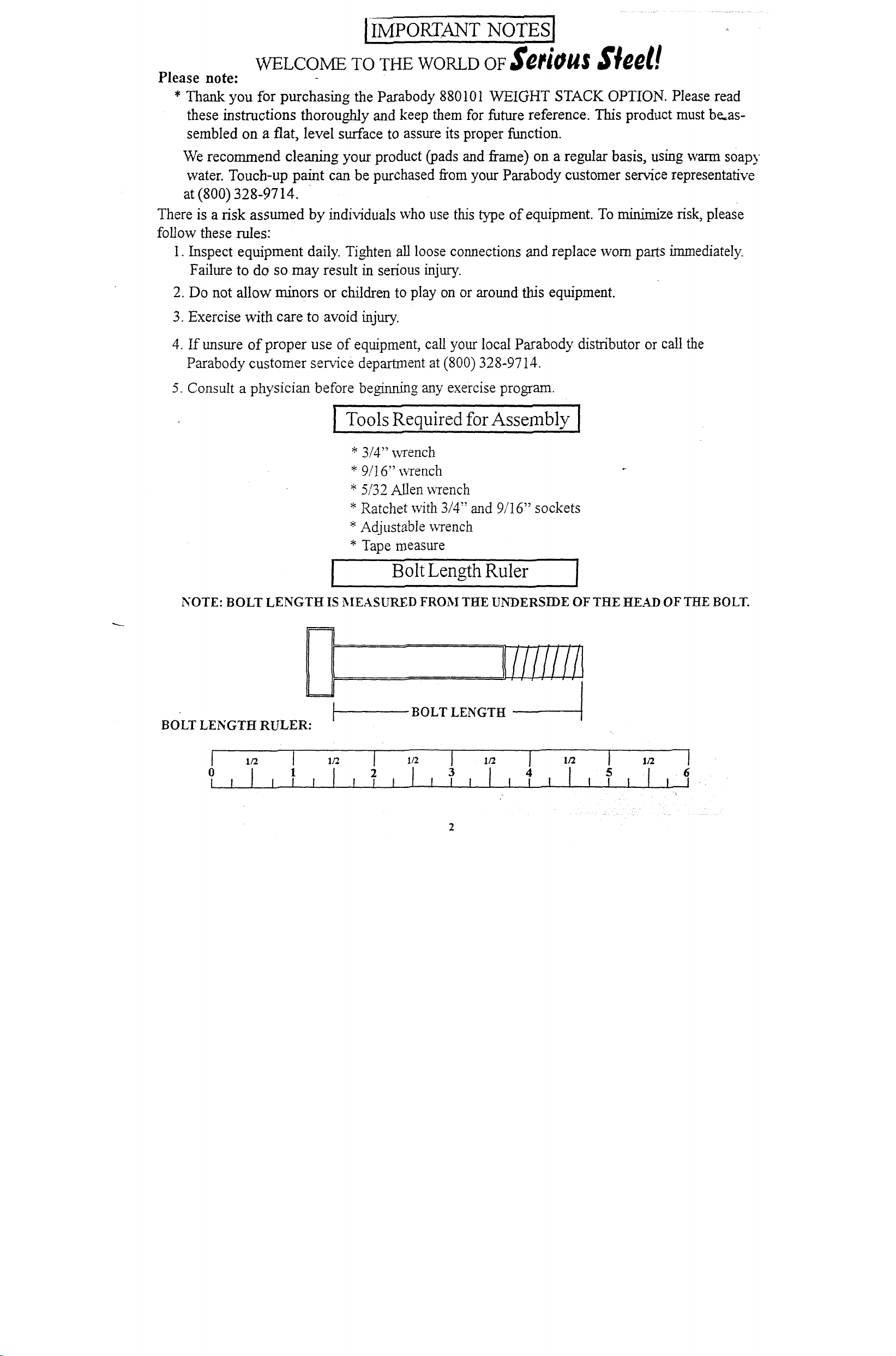
i ro,,o~~ aequired I
* 3/4" wrench
*
9/16" wrench
* 5/32 Allen wrench
* Ratchet with 3/4" and 9/16" sockets
* Adjustable wrench
Tape measure
*
’Bolt Length Ruler
NOTE: BOLT LENGTH IS MEASURED FROM THE UNDERSI~DE OF THE HEAD OF THE BOLT.
~111iiiiil
BOLT LENGTH RULER:
BOLT LENGTH
3
4
Page 3
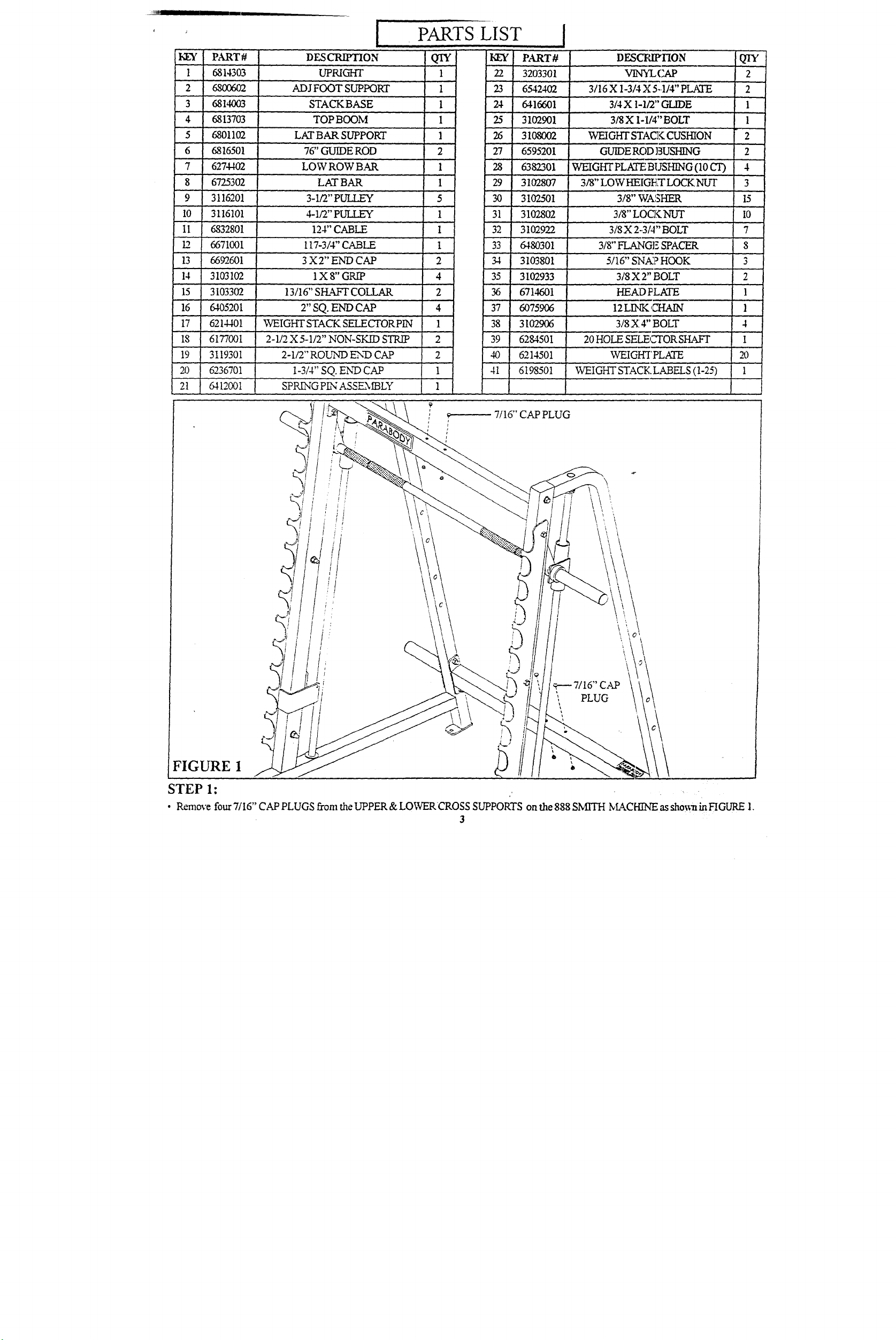
PARTS LIST
~
17 6214401 WEIGHT STACK SH_ECTOR HN
18 6177001
19
20 6236701
PART# DESCRIPTION
1 6814303 UPRIGHT
2 680(Y~
3 681,1(~3 STACKBASE
4 68 13703 TOP B OOM
5 6801102
6 6816501 76" GUIDE ROD
7 6274402 LOW ROW B.M:~
6725302
8
9 3116201 3-1/’2" PUI !.EY
il
6832801 124" CABLE 1 32
12 66710bi li7-3/4" CABLE 1 33
14 3103102
15 3103302 13/16" SH.~T COLLAR 2 36
640J2~)i
3119301 2-1/2" ROUND END CAP 2
ADJ" FOOT SUPPORT 1 23
LAT BAR SUPPORT 1 26
’ ’ LATBAR
’"
lxs"GRn~ 4
2"’SQ. END’ CAP 4 37
2-1/2 X 5’-1/2" NO~q-SKXD STR/P
QTY
1
1 24
1
2
1
I’ 29
5
1 38
2 39
I-3/4"SQ.E~VCAr’1 41
kEY
30
PART #
22
3203301
6542402
6416601
25
3102901
3108002
27
6595201
28
6382301
31 02807 3?8" LOW HEIGE~T LOCK NUT
3102501 3/8" WASHER
3102802 3/8" LOCK NUT
3102922 3/8 X 2.3/4" BOLT
WEIGHT PLATE BUSHING (10 CT)
DESCRIFHON
3/16 X 1-3/4 X 5.,1/4" PLATE
3/4 X 1-1:2" GLIDE
3/8 X I-1/4" BOLT
WEIGHT STAC~ CUSHION
GUIDE ROD BUSHING
6480301 3/8-~,.~G~Z Sr’AC~
3103801 5/16" SNh£? HOOK
35
310293~
671’4601 HEKD PLATE
6075906 12 LINK CT-/AIN
3102906 3/8 X 4" BOLT
40
6284501
6214501
6198501
20 HOLE SELECTORSHAFT
WEIGHT STACK LABELS (1-25)
3/8 X 2" BOLT
WEIGHT PLATE
VIN5%CAP
2
2
’1
1
"2
2
4
3
15
I0
7
"8
2
1
1
4
1
1
, 7116" CAP PLUG
FIGURE I
~
STEP 1: ,
¯ Remove four 7/16" CAP PLUGS from the UPPER & LOWERCROSS SUPPORTS on the 888 SMFFH NLZC[-HNE as sho~aain HGURE 1.
3
¯
¯
Page 4

FIGURE 2
STEP 2:
¯ Insert two 2" END CAP (16) into the ends of the STACK BASE (3) as shown in FIGURE
¯
Attach fou~ 3/4 X 1-1/2" GLIDES (24) to the inside of the tube on the STACK BASE (3) as shown in FIGURE 2 using the
following steps:
¯
Thoroughly clean all surfaces where the 3/4 X 1-1/2" GLIDES (24) are to be attached.
¯
Remove the 3/4 X 1-1/2" GLIDES (24) from the paper backing and firefly apply them to all shown surfaces.
SECURELY assemble one SPRh-NG PLY" ASSEN~LY (21) to the spring pkn barrel on the STACK BASE (3). See FIGUP~
FIGURE 3
STEP 3:
¯
Insert two 2-1/2" ROUND END CAPS (19) into the ends of the ADJ. FOOT SUPPORT (2) as shown in FIGURE
¯
Insert one 1-3/4" END CAP (20) into the end of the ADJ. FOOT SUPPORT (2) as sho~:n in FIGURE
¯
Apply m’o 2-1/2 X 5-1/2" NON-SKID STR.~S (18) to the ADJ. FOOT SUPPORT (2) as shown in FIGURE
¯ Attach four 3/4 X 1-1/2"’ GLIDES (24) so the outside of the ADJ FOOT SUPPORT (2) as shoss~ in FIGURE 3 using the
follo~s4ng steps:
¯
Thorou~ly clean all surfaces where the 3/4 X 1-I/2" GLIDES (24) are to be attached.
¯
Remove the 3/4 X 1-1/2" GLIDES (24) from the paper backing and firmly apply them to all sho~ surfaces.
] ,/2 1’ l~z [ ~/’z I ~/~. [ l~z [ .I/2 ....
0
1.
2
3
4
[’ 4
5
6
Page 5

STEP 6:
Insert two GUIDE RODS (6) imo the STACK
BASE (3) as sho~ai in.FIGURE 6. Lubricate the
GUIDE RODS (6) with a slicon or teflon spray
that is available at most hard~are stor~s.
¯
Slide two WEIGftT STACK CUSHIONS (26)
dox~ over the GUIDE RODS (6). See HGURE
Using EXTREI~[F, GKRE slide t~m~t3." WEIGHT
PLATES (40) down over the GUIDE RODS (6)
with the key-hole facq~g as .~hownin FIGLqLE 6.
Securely assemble £~te 20 HOLE SELECTOR
SHAFT (39) to the HEAD PLATE (36) using
one 3/8 X 1-1/4" BOLT (25) and one 3/8"
WASHER (30). (Note: The bolt hole in
HEAD PLATE (36) should be on top.)
CarefuIly Slide ~e IKE.a39 PLATE AS SE~X~ LY
(36 & 39) do~ over the GUIDE RODS (6)
the weight stack as :;hown in FIGLqLE 6.
¯
Slide two 13116" SFLA~T COLLASL5 (15) over
~e GUIDE RODS (6) as sho~wt ~ FIGURE
Apply one set of WFIGHT STACK L~EL5 -
1-25 (41) to each WEIGHT PLATE (40) as sh:’a-n
inFIGURE 6.
FIGURE 6
4
I
Page 6

318 X 4
LOWER CROSS SUPPORT "
FIGURE 4
STEP 4:
¯
NOTEi It may be necessa~" to loosen the 1/2 X 3-1/4" BOLTS of the LOWER CROSS SUPPORT connecting to the IiPRIGI~IT
FR.~%IE before beginnlngSTEP 4.
¯
SECURELY assemble the STACK BASE (3) and the UPRIGHT (1) to the LOWER CROSS SUPPORT using two 3/8 X 4" BOLTS (38).
four 3/8" WASHERS (30), and two 3/8" LOWHEIGHT LOCKNUT5 (29). See FIGURE
¯
Pull back on the SPREgG PEg (21) and C.~REFULLY insert the ADJ. FOOT SUPPORT (2) into the STACK BASE (3) as shox~’n
FIGLrRE 4.
¯ Retighten the 1/2 X 3-1/4" BOLTS loosened in the above STER
STEP 5:
¯
Sn.ap two Vc~IGHT PLATE BUSHEgGS (28) into the
top of all twenty WEIGHT PLATES (40) as shown
FIGURE 5.
Page 7

FIGURE
3/8" LOW HEIGHT~
3/8 X 2-3/4
STEP 8:
¯ SECURELY assemble the LAT BAR SUPPORT (5) to the TOP BOOM (4) using one 3/8 X 2-3/4" (32) and one 3/8" LOWHEIGH~
NUT (29). See HGURE
¯ Slide two VINYL CAPS (22) over the LAT BAK SUPPORT (5) as sho~ in FIGUPOE
FIGURE 9
CABLE
is routed over bolt!
STEP 9:
¯
Route the 117-3/4" CABLE (12) throu~h the TOP BOOM (4) as sho~a in FIGURE 9. (NOTE: It may be necessa~" to remove 3/8
X 2~-3/4" BOLT to ensure CABLE is routed over the TOP.. of the BOLT.)
¯ SECURELY assemble three 3-1/2" PULLEYS (9)in!o the slots of the TOP BOOl~ I (4) using three 3/8 X 2-3/4" BOLTS (32), six 3i~" FLA_\’GE
SPACERS (33), and three 3/8" LOCK NLrI’S (3 I) as show~ in FIGURE 9. (NOTE: Make sure the cable is routed over all the pulleys.)
3/8X2_3/4.,~//
¯ SECURELY retighten the removed 3/8 X 2-3/4" BOLT from the above step.
I 1/2 [ 1/2 [ 1/2 [ I/2 [ 1/2 I 1/2 ¯ "!
Page 8

FIGURE 7
;
SUPPORT
3/8 X 4"
STEP 7:
¯
NOTE: It may be necessary to loosen the 1/2 X 3-1/4" BOLTS of the UPPER CROSS SUPPORT connecting the UPRIGHT
FRA~IE before be~rming STEP 7.
Insert two GUIDE ROD BUSI-I~GS (27) into the TOP BOOM (4) as sho~:n in HGURE
Insert two 3 X 2" END CAPS (13) into the ends of the TOP BOOM (4). See FIGURE
3/8 X 2-3/4"
Insert two 2" SQ. END CAPS (16) into the ends of the TOP BOOM (4). See FIGURE
Place TOP BOOM (4) over the GUIDE RODS (6) and LOOSELY assemble the TOP BOOM (4) to the LrpRIGHT (1) using one
3/4" BOLT (32) and one 3/8" LOCK NUT (31) as shown in FIGURE
LOOSELY assemble the TOP BOOM (4) to the UPPER CROSS SUPPORT using two 3/8 X 4" BOLTS (38), four 3/8" V,:-kS~
and two 3/8" LOCK NI51"S (31). See FIGURE
Slide the 13/16" SHAFT COLLARS (15) to the top of the GUIDE RODS (6) and SECURELY tighten the SHAFT COLLA.R (15)
screws. See FIGURE 7.
SECURELY tighten all connections made up to fl’tis point.
7
Page 9

FIGURE 11
STEP 11:
Route the threaded end of the 124" CABLE (I 1) through the slot oft.he UPRIGHT (1) then SECURELY assemble one 4-1/2" PULLEY
(10) to the UPRIGHT (I) using m’o 3/8 X 2-3/4" BOLTS (32), two 3/8" FLANGE SPACERS (33), two 3/8" W~_SHERS (30), and
LOCK NUTS (31). (NOTE: The CABLE (11) should be muted bem’een the pulley and the retaining bolt as :~hown in FIGURE
10
Page 10

FIGURE 10
"(~3/8 X 2"
STEP 10:
¯ Screw the threaded end of the CABLE (12) appro~mately 3/4" into the end of the 20 HOLE SELECTOR SI-I.4k-T (39) and tighten
nut securely. See FIGURE 10.
¯
PlaCe one 3-1/2" PULLEY (9) into the loop of the CABLE (12) below the second and third PULLEY of the TOP BOOM (4) as
in HGURE 10.
¯
LOOSELY assemble two 3/16 X 1-3/4 X 5-1/4" PLATES (23) to each side of the 3-1/2" PULLEY (9) using one 3/8 X 2" BOLT (35),
two 3/8" WASHERS (30), and one 3/8" LOCK NUT (31). See FIGURE 10.
 Loading...