

877102 BODYSMITH NARROW
WORKOUT CENTER
ASSEMBLY INSTRUCTIONS
Part # 6757301 Revision:1/12/981
IMPORTANT NOTES
Please note:
WELCOME TO THE WORLD OF Serious steel!
* Thank you for purchasing the Parabody 877102 BODYSMITH NARROW WORKOUT
CENTER. Please read these instructions thoroughly and keep them for future reference. This
product must be assembled on a flat, level surface to assure its proper function.
* We recommend cleaning your product (pads and frame) on a regular basis, using warm soapy
water. Touch-up paint can be purchased from your Parabody customer service representative
at (800) 328-9714.
There is a risk assumed by individuals who use this type of equipment. To minimize risk, please
follow these rules:
1. Inspect equipment daily . T ighten all loose connections and replace worn parts immediately.
Failure to do so may result in serious injury.
2. Do not allow minors or children to play on or around this equipment.
3. Exercise with care to avoid injury .
4. If unsure of proper use of equipment, call your local Parabody distributor or call the
Parabody customer service department at (800) 328-9714.
5. Consult a physician before beginning any exercise program.
T ools Required for Assembly
* 3/4” wrench
* 9/16” wrench
* Ratchet with 3/4” and 9/16” sockets
* Adjustable wrench
* Tape measure
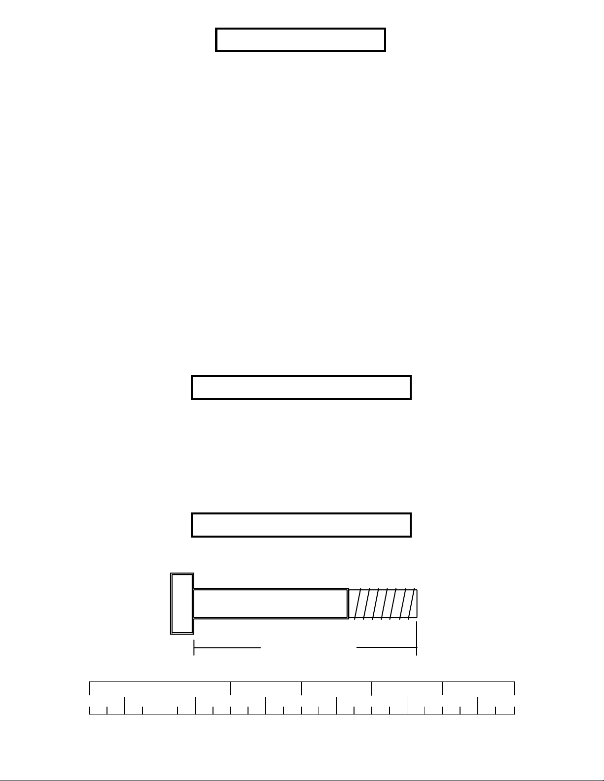
Bolt Length Ruler
NOTE: BOL T LENGTH IS MEASURED FROM THE UNDERSIDE OF THE HEAD OF THE BOLT.
BOL T LENGTH RULER:
1/2 1/2 1/2 1/2 1/2 1/2
0
1
BOLT LENGTH
2
345
2
6

PARTS LIST
KEY
1
2
3
4
5
6
7
8
9
10
11
12
13
14
15
PART #
6407103
6407503
6100402
6406602
6407802
6407302
6407202
6024702
6406401
6406501
6125101
6194601
6654502
6654102
3102909
DESCRIPTION
UPRIGHT FRAME
BENCH FRAME
HEIGHT ADJUSTMENT BAR
WOLFF SLEEVE
BASE LEG
SADDLE
LEG EXTENSION NECK
LEG EXTENSION
HINGE TAB
U-PIN
ROLLER PAD SHAFT
ROLLER PAD
SEAT PAD
BACK PAD
3/8 X 1” BOLT
QTY
1
1
1
1
1
2
1
1
4
2
2
6
1
1
4
16
17
18
19
20
21
22
23
24
25
26
27
28
29
30
31
3102922
3102904
3102910
3102501
3102601
3102804
3102502
6236701
3102804
6412001
6020601
3105401
3109602
6145801
3103101
6416601
3/8 X 2-3/4” BOLT
3/8 X 3” BOLT
1/2 X 3” BOLT
3/8” WASHER
3/8” LOCK WASHER
3/8” LOCK NUT
1/2” WASHER
1-3/4” SQ. END CAP
1/2” LOW HEIGHT LOCK NUT
3/8” SPRING PIN ASSEMBLY
1/2” FLANGE BEARING
3/4” STARLOCK COLLAR
PAL NUT
THUMBSCREW
1-1/4 X 5” GRIP
PARAGLIDE STRIP (8 ct.)
1
2
1
10
4
3
2
4
1
3
2
6
2
4
2
3
32
33
3104301
6405201
3/4” SQ. RUBBER BUMPER
2” SQ. END CAP
3
1
6
25
28
4
10
31
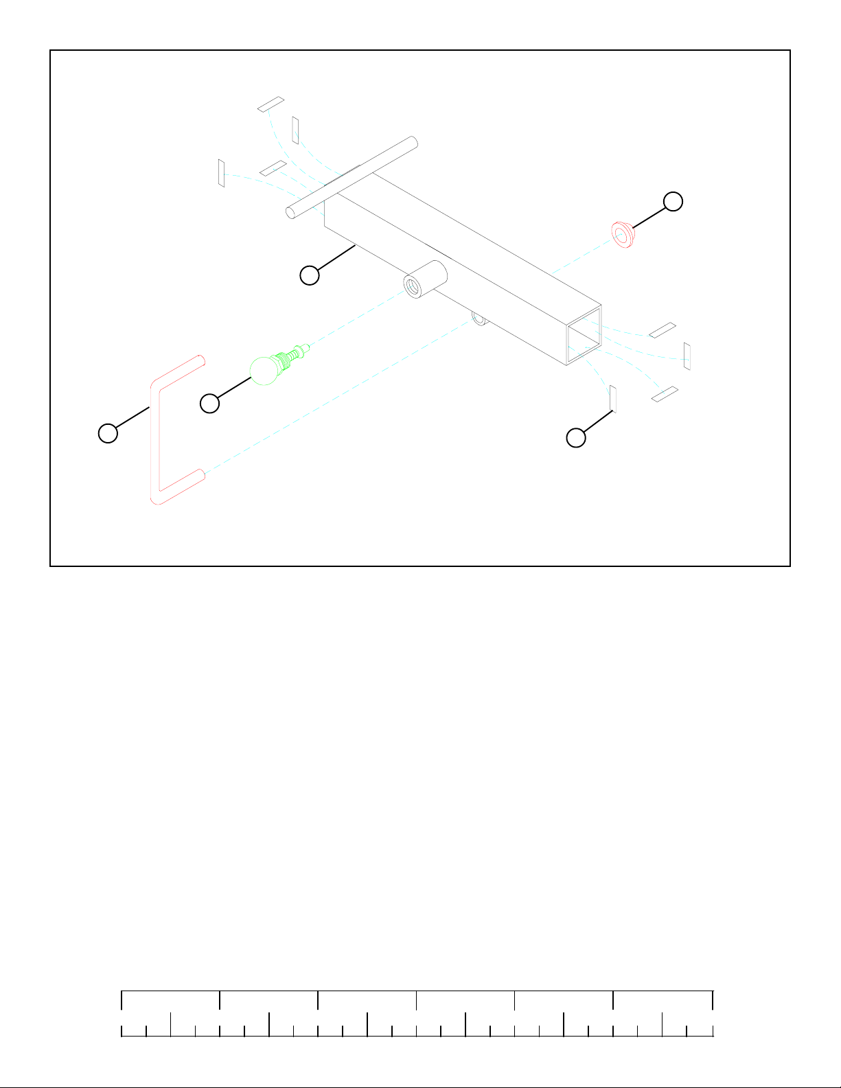
FIGURE 1
STEP 1:
• Attach eight PARAGLIDE STRIPS (31) to the WOLFF SLEEVE (4) (FOUR ON EACH END) as shown in FIGURE 1 using the
following steps:
• Thoroughly clean all surfaces where the PARAGLIDE STRIPS are to be attached.
• Remove the PARAGLIDE STRIPS from the paper backing and firmly apply them to all shown surfaces.
• Insert one U-PIN (10) through the BUSHING of the WOLFF SLEEVE (4) and attach one PAL NUT (28) to the end of the U-PIN
(10) as shown in FIGURE 1.
• SECURELY assemble one 3/8” SPRING PIN ASSEMBLY (25) to the SPRING PIN HOUSING on the WOLFF SLEEVE (4) as
shown in FIGURE 1. (!!! IMPORTANT !!! TIGHTEN THE NUT OF THE SPRING PIN ASSEMBLY SECURELY)
1/2 1/2 1/2 1/2 1/2 1/2
1/2 1/2 1/2 1/2 1/2 1/2
0
0
1
1
2
2
345
345
4
6
6

4
2
28
10
5
TAB
33
FIGURE 2
STEP 2:
• Pull back the SPRING PIN on the WOLFF SLEEVE (4) and slide it over the end of the BENCH FRAME (2) as shown in
FIGURE 2. Engage the SPRING PIN into one of the adjustment holes.
• Insert two 2” SQ. END CAPS (33) into both ends of the BASE LEG (5) as shown in FIGURE 2.
• Insert one U-PIN (10) through the BUSHING on the bottom of BENCH FRAME (2) and attach one PAL NUT (28) to the end of
the U-PIN (10) as shown in FIGURE 2.
• Insert the BASE LEG (5) into the front of the BENCH FRAME (2) as shown in FIGURE 2. (MAKE SURE THAT THE TAB
ON THE BASE LEG IS UNDER THE BENCH FRAME)
5

25
3/8 X 2-3/4” 16
19
33
21
21
19
3/8 X 3” 17
1
4
33
2
29
FIGURE 3
STEP 3:
• Insert four 2” SQ. END CAPS (33) into the BASE TUBES of the UPRIGHT FRAME (1) as shown in FIGURE 3.
• SECURELY assemble the BENCH FRAME (2) to the UPRIGHT FRAME (1) using two 3/8 X 3” BOLTS (17), one 3/8 X 2-3/
4” BOLT (16), six 3/8” WASHERS (19), and three 3/8” LOCK NUTS (21) as shown in FIGURE 3.
• SECURELY assemble two 3/8” SPRING PIN ASSEMBLIES (25) to the SPRING PIN HOUSING on the UPRIGHT FRAME (1)
as shown in FIGURE 3. (NOTE: !!!IMPORTANT!!! Tighten the nut of the SPRING PIN ASSEMBLY SECURELY!)
• Secure the WOLFF SLEEVE (4) in place with one THUMBSCREW (29).
1/2 1/2 1/2 1/2 1/2 1/2
0
1
2
345
6
6

30
6
31
29
1
31
FIGURE 4
STEP 4:
• Attach eight PARAGLIDE STRIPS (31) to both UPRIGHT TUBES on the UPRIGHT FRAME (1) (FOUR ON EACH END) as
shown in FIGURE 4 using the following steps:
• Thoroughly clean all surfaces where the PARAGLIDE STRIPS are to be attached.
• Remove the PARAGLIDE STRIPS from the paper backing and firmly apply them to all shown surfaces.
• Attach eight PARAGLIDE STRIPS (31) to each SADDLE (6) (FOUR ON EACH END) as shown in FIGURE 4.
• Slide two 1-1/4 X 5” GRIPS (30) over the DIP HANDLES of both SADDLES (6). (IF A LUBRICANT IS REQUIRED, COAT
THE INSIDE OF THE GRIP WITH RUBBING ALCOHOL.)
• Pull back the SPRING PIN on the UPRIGHT TUBES, and insert the SADDLES (6) as shown in FIGURE 4.. Slide the SADDLE
(6) down to the desired height and release the SPRING PIN into the hole.
• Secure the SADDLES (6) in place with two THUMBSCREWS (29) as shown in FIGURE 4. When ready to perform the DIP
EXERCISE, simply insert the SADDLES (6) into the UPRIGHT TUBES and tighten the two THUMBSCREWS
7

19
13
9
4
20
3/8 X 1” 15
FIGURE 5
STEP 5:
• To assemble the SEAT PAD (13) to the WOLFF SLEEVE (4), start by sliding two HINGE TABS (9) over the PIN of the
WOLFF SLEEVE (ONE ON EACH SIDE) as shown in FIGURE 5, and SECURELY assemble each HINGE TAB (9) to the
SEAT PAD (13) using two 3/8 X 1” BOLTS (15), two 3/8” LOCK WASHERS (20), and two 3/8” WASHERS (19). (MAKE
SURE BOTH HINGE TABS ARE ALL THE WAY ON THE PIN)
1/2 1/2 1/2 1/2 1/2 1/2
0
1
2
345
8
6

19
20
3/8 X 1” 15
14
9
4
FIGURE 6
STEP 6:
• To assemble the BACK PAD (14) to the WOLFF SLEEVE (4), slide the two remaining HINGE TABS (9) over the PIN of the
WOLFF SLEEVE (ONE ON EACH SIDE) as shown in FIGURE 6, and SECURELY assemble each HINGE TAB (9) to the
BACK PAD (14) using two 3/8 X 1” BOLTS (15), two 3/8” LOCK WASHERS (20), and two 3/8” WASHERS (19). (MAKE
SURE BOTH HINGE TABS ARE ALL THE WAY ON THE PIN)
9

23
27
29
12
7
2
FIGURE 7
STEP 7:
• Insert one 1-3/4” SQ. END CAP (23) into the top of the LEG EXTENSION NECK (7) as shown in FIGURE 7.
• Slide two ROLLER PADS (12) over each end of the SHAFT of the LEG EXTENSION NECK (7), as shown in FIGURE 7, and
secure in place using two 3/4” STARLOCK COLLARS (27).
• Insert the LEG EXTENSION NECK (7) into the BENCH FRAME (2) and secure in place using on THUMBSCREW (29) as
shown in FIGURE 7.
1/2 1/2 1/2 1/2 1/2 1/2
0
1
2
345
10
6

LOW HEIGHT 24
7
22
32
18 1/2 X 3”
26
12
27
11
8
23
FIGURE 8
STEP 8:
• Insert three 1-3/4” SQ. END CAPS (23) into the ends of the LEG EXTENSION (8) as shown in FIGURE 8.
• Insert two 1/2” FLANGE BEARINGS (26) into the BUSHING on the LEG EXTENSION (8) as shown in FIGURE 8.
• Assemble the LEG EXTENSION (8) to the LEG EXTENSION NECK (7) as shown in FIGURE 8, using one 1/2 X 3” BOLT
(18), two 1/2” WASHERS (22), and one 1/2” LOW HEIGHT LOCK NUT (24). (TIGHTEN THE CONNECTION ENOUGH
TO REMOVE THE PLAY, YET ALLOWING THE LEG EXTENSION TO ROTATE FREELY)
• Assemble four ROLLER PADS (12) to the LEG EXTENSION (8) as shown in FIGURE 8, using two ROLLER PAD SHAFTS
(11), and four 3/4” STARLOCK COLLARS (27).
• Attach one 3/4” SQ. RUBBER BUMPER (32) to the LEG EXTENSION (8) approximately where shown in FIGURE 8.
11

2
10
5
FIGURE 9
STEP 9:
• When ready to perform LEG CURLS or LEG EXTENSION, pull up slowly on the front of the BENCH FRAME (2) and allow
the U-PIN (10) to rest on top of the TAB of the BASE LEG (5). (NOTE: THE BENCH FRAME MUST BE ADJUSTED UP
WHEN USING THE LEG EXTENSION TO ALLOW PROPER CLEARANCE FOR WEIGHT PLATES)
1/2 1/2 1/2 1/2 1/2 1/2
0
1
2
345
12
6

1
3
FIGURE 10
STEP 10:
• Set the HEIGHT ADJUSTMENT BAR (3) across the UPRIGHT FRAME (1) as shown in FIGURE 10, for performing INCLINE,
or MILITARY PRESSES. When performing DIPS, use the HEIGHT ADJUSTMENT BAR (3) to hold the BACK PAD forward
as shown in the WORKOUT MANUAL.
• Follow the WORKOUT MANUAL for the correct way to use this product.
THIS CONCLUDES THE ASSEMBLY OF THE 877102 BODYSMITH NARROW
WORKOUT CENTER
13
 Loading...