

868
WEIGHT STACK OPTION
PRODUCT ASSEMBLY
INSTRUCTIONS SHEETS
RF.’~’ISION A
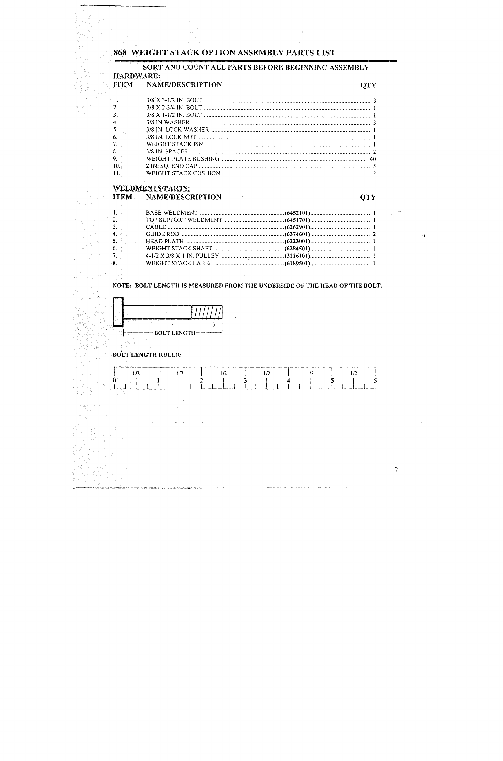
868 WEIGHT STACK OPTION ASSEMBLY PARTS LIST
SORT AND COUNT ALL PARTS BEFORE BEGINNING ASSEMBLY
HARDWARE:
ITEM NAME/DESCRIPTION QTY
3/8 X 3-I/2 IN. BOLT .............................................................................................................
2.
3.
4.
5.
6.
7.
8.
9.
10.
I1.
3/8 X 2-3/4 IN. BOLT .............................................................................................................
3/8 X I-1/2
3/8 IN WASHER .....................................................................................................................
3/8 IN. LOCK WASHER ........................................................................................................
3/8 IN. LOCK NUT ................................................................................................................
WEIGHT STACK PIN ............................................................................................................
3/8 IN. SPACER ..................................................................................................................... 2
WEIGHT PLATE BUSHING ............................................................................................... 40
2 IN. SQ. END CAP ................................................................................................................. 5
WEIGHT STACK CUSI-I1ON .................................................................................................
IN. BOLT ............................................................................................................. 1
YqELDMENTS/PARTS:
ITEM NAME/DESCRIPTION
BASE WELDMENT .......................................................
2.
3.
4.
5.
6.
7.
8.
TOP SUPPORT WELDMENT ....................................... (6451701) ....................................... 1
CABLE ............................................................................
GUIDE ROD ................................................................... (6374601) ....................................... 2
HEAD PLATE ................................................................ (6223001) ....................................... 1
WEIGHT STACK SHAFT .............................................. (6284501) ....................................... 1
4-.I/2 X 3/8 X 1 IN. PULLEY ......................................... (3116101) ....................................... 1
WEIGHT STACK LABEL ............................................. (6189501) ....................................... 1
(6452101) .......................................
(6262901) ........................................
3
1
3
1
1
I
2
1
NOTE: BOLT LENGTH IS MEASURED FROM THE UNDERSIDE OF THE HEAD OF TIlE BOLT.
BO:LT LENGTH RULER:
0 1
I
2 6
I 1 1 I, I
868 WEI.GHT STACK OPTION ASSEMBLY INSTRUCTIONS
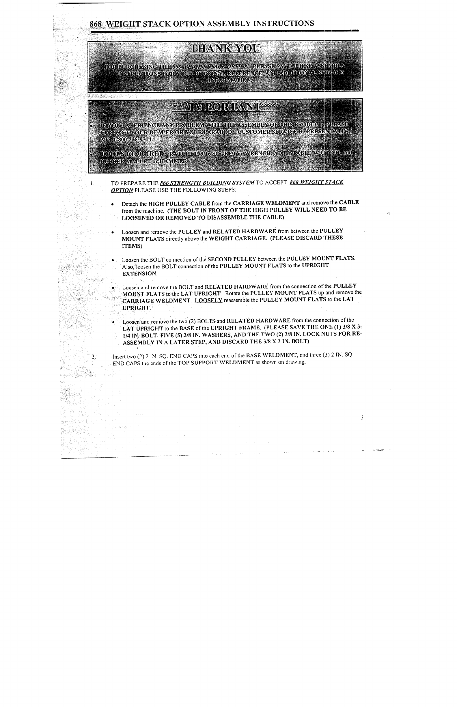
TO PREPARE THE 866 STRENGTH BUILDING SYSTEM TO ACCEPT 868 WEIGHT SZ~CK
OPTION PLEASE USE THE FOLLOWING STEPS:
Detach the HIGH PULLEY CABLE from the CARRIAGE WELDMENT and remove the CABLE
from the machine. (THE BOLT IN FRONT OF THE HIGH PULLEY WILL NEED TO BE
LOOSENED OR REMOVED TO DISASSEMBLE THE CABLE)
Loosen and remove tlae PULLEY and RELATED HARDWARE from between the PULLEY
MOUNT FLATS directly above the WEIGHT CARRIAGE. (PLEASE DISCARD THESE
ITEMS)
Loosen the BOLT connection of the SECOND PULLEY between the PULLEY MOUN’I[" FLATS.
Also, loosen the BOLT connection of the PULLEY MOUNT FLATS to the UPRIGHT
EXTENSION.
Loosen and remove the BOLT and RELATED HARDWARE from the connection of the PULLEY
MOUNT FLATS tOthe LAT UPRIGHT. Rotate the PULLEY MOUNT FLATS up an,:l remove the
CARRIAGE WELDMENT. LOOSELY reassemble the PULLEY MOUNT FLATS t~ the LAT
UPRIGHT.
¯
Loosen and remove the two (2) BOLTS.and RELATED HARDWARE from the connection of the
LAT UPRIGHT to the BASE of the UPRIGHT FRAME. (PLEASE SAVE THE ONE (1) 3/8 X
I/4 IN. BOLT, FIVE (5) 3/8 IN. WASHERS, AND THE TWO (2) 3/8 IN. LOCK NU’I?S FOR
ASSEMBLY IN A LATER ~TEP, AND DISCARD THE 3/8 X 3 IN. BOLT)
Insert two (2) 2 IN. SO. END CAPS into each end of the BASE WELDMENT, and three (3) :2 IN.
END CAPS the ends of the TOP SUPPORT WELDMENT as shown on drawing.

868 WEIGHT STACK OPTION ASSEMBLY INSTRUCTIONS
SECURELY assemble one (I) 4-1/2 X 3/8 X 1 IN. PULLEY, and two (2) 3/8 IN. SPACERSIo the
SUPPORT WELDMENT as shown on drawing using one (1) 3/8 X 2-3/4 IN. BOLT, two (2~)3/8
WASHERS, and one (1) 3/8 IN. LOCK NUT.
LOOSELY assemble tile BASE WELDMENT to the BASE of the LAT UPRIGHT as shown on the
CABLE ROUTING DIAGRAM in the following order:
LOOSELY assemble one (1) 3/8 X 3-1/2 IN. BOLT along with the CABLE to the inside hole of the
BASE WELDMENT. Re-use the three (3) 3/8 IN. WASHERS, and one (I) 3/8 IN. LOCK NUT
STEP 1. (PLEASE SEE THE CABLE ROUTING DIAGRAM)
LOOSELY assemble the EXISTING 3/8 X 3-1/4 IN. BOLT, two (2) 3/8 IN. WASHERS, and one (1)
3/8 IN. LOCK NUT from STEP I for the outside hole of the BASE WELDMENT. (PLEASE SEE
THE CABLE ROUTING DIAGRAM)
Insert the GUIDE RODS into the holes of the BASE WELDMENT as shown on drawing, and allow them
to tilt back. (NOTE: LUBRICATE GUIDE RODS WITH A SILICON OR TEFLON SPRAY THAT
IS AVAILABLE AT MOST HARDWARE STORES)
Slide two (2) WEIGHT STACK CUSHIONS (RADIUS EDGE FACING UP) down over the GUIDE
RODS as shown on drawing.
10.
13.
SECURELY assemble the WEIGHT STACK SHAFT to the ltEAD PLATE as shown on d~:awing, using
one (1) 3/8 X I-1/2 IN. BOLT, one (1) 3/8 IN. LOCK WASHER, and one (I) 3/8 IN. WASHER.
Snap two (2) WEIGHT PLATE BUSHINGS each, into twenty (20) WEIGHT PLATES as shown
(DETAIL A).
USING EXTREME CARE slide all twenty (20) WEIGHT PLATES down over the GUIDE RODS
onto the WEIGHT STACK CUSHIONS as shown on drawing. (MAKE SURE THAT TEE KEY
HOLES OF THE WEIGHT PLATES ARE ALL FACING THE SAME WAY)
Slide the HEAD PLATE ASSEMBLY down over the GUIDE RODS onto the WEIGHT STACK as
shown on drawing.
Slide the TOP SUPPORT WELDMENT over the GUIDE RODS as shown on drawing.
Remove the NUTS and WASHERS flom the !wo (2) loosened BOLT connections on tile PULLEY
MOUNT FLAT.S above the WEIGHT STACK as shown. Swing the TOP SUPPORT WELDMENT
over the top of the two (2) BOI~TS. When the TOP SUPPOR.T is in position ,cplace these two (2)
existing BOLTS with two (2) 3/8 X 3-1/2 IN. BOLTS (ONE AT A TIME). SECURELY assemble
WASHERS and NUTS to the BOLTS. (SEE DRAWING)
SECURELY tighten the BOLT connections of the BASE WELDMENT from STEP 4. (MAKE SURE
THAT THE LOW PIJIAA~.Y (.’ABIA{ IS RUNNING VERTICALLY BEFORE TIGHTENING)

868 .WEIGHT STACK OPTION ASSEMBLY INSTRUCTIONS
14. To assemble the WEIGHT STACK CABLE, follow the cable routing diagram on drawing, and use the
following steps:
Route the threaded end of the WEIGHT STACK CABLE over the HIGH PULLEY between the
PULLEY MOUNT FLATS. Then reassemble the one (1) 3/8 X 3-1/4 IN. BOLT and REL?~TED
HARDWARE to the hole in front of the HIGH PULLEY (IF NECESSARY). (DO NOT OVER
TIGHTEN BOLT) (MAKE SURE THAT THE CABLE IS BETWEEN THE PULLEY AND
BOLT)
Continue the CABLE down to the SECOND PULLEY between the PULLEY MOUNT FLATS.
Pull the CABLE over this PULLEY and down to the PULLEY BLOCK.
¯
Continuethe CABLE around the TOP PULLEY of the PULLEY BLOCK and up to the PULLEY
of the TOP SUPPORT WELDMENT above the WEIGHT STACK..
Continue the CABLE over and down this PULLEY to the WEIGHT STACK, and SECURELY
assemble the CABLE to the WEIGHT STACK SHAFT of the HEAD PLATE as shown i~a the
CABLE ROUTING DIAGRAM.
¯
See CABLE ROUTING DIAGRAM for help in completing this step.
15. Attach the WEIGHT STACK LABELS to the WEIGHT STACK as shown on drawing.
16. To select WEIGHT, rotate the WEIGHT STACK SELECTOR PIN clock wise 90 degrees, inse;t into the
slot of the desired WEIGHT PLATE, and rotate the PIN back down.

01 AS SHOWN
/
3/8 IN WASHER (2)
3/8 X 2-3/4 IN
I
I
I
I
pULLEYMOUNT FLATS (2~--~
UPRIGHT EXTENSION
UPRIGHT FRAME
EXISTING 3/8 IN LOCK NUT (2)~
BASE
WEIGHT STACK LABELS
WEIGHT PLATES (20)-
STACK CUSHION (2)-
WEIGHT
BASE WELDMENT
EXISTING 3/

-4--1/2 X 3/8 X 1 IN PULLEY
5/8 X .3/8 X 3/8 1N SPACER (2)
S
~
2 IN SQ END CAP (.3)
~.~-TOP SUPPORT WELDMENT .....
EXISTING ,3/8 IN WASHER (4-)
EXISTING 3/8 IN LOCK NUT (2)
HEAD PLATE
IN WASHER
IN LOCKWASHER
.3/8 X 1-1/2 IN BOLT
GUIDE ROD (2)
’,’,;EIGHT PL.ATE E:USHING
DETAIL A
WEIGHT
(2)
PLATE
SERIAL NUMBER
BETWEEN WASHERS
ILE
WASHER (5)
EXISTING 3/8 X ,3-1/4 IN BOLT
‘3/8 X 3-1./2 IN
PULLEY BLOCK
CONNECT TO WEICHT STACK
CABLE
o
ROUTING DIAGRAk4
 Loading...