

Page 1
848101 LAT OPTION
Part # 6826701
ASSEMBLY INSTRUCTIONS
1
Revision: 5/26/99
Page 2
IMPORTANT NOTES
WELCOME TO THE WORLD OF Serious steel!
Please note:
* Thank you for purchasing the Parabody 848101 LAT OPTION. Please read these instructions
thoroughly and keep them for future reference. This product must be assembled on a flat, level
surface to assure its proper function.
We recommend cleaning your product (pads and frame) on a regular basis, using warm soapy
water. Touch-up paint can be purchased from your Parabody customer service representative
at (800) 328-9714.
There is a risk assumed by individuals who use this type of equipment. To minimize risk, please
follow these rules:
1. Inspect equipment daily . T ighten all loose connections and replace worn parts immediately.
Failure to do so may result in serious injury.
2. Do not allow minors or children to play on or around this equipment.
3. Exercise with care to avoid injury .
4. If unsure of proper use of equipment, call your local Parabody distributor or call the
Parabody customer service department at (800) 328-9714.
5. Consult a physician before beginning any exercise program.
T ools Required for Assembly
* 3/4” wrench
* 9/16” wrench
* Ratchet with 3/4” and 9/16” sockets
* Adjustable wrench
* Tape measure
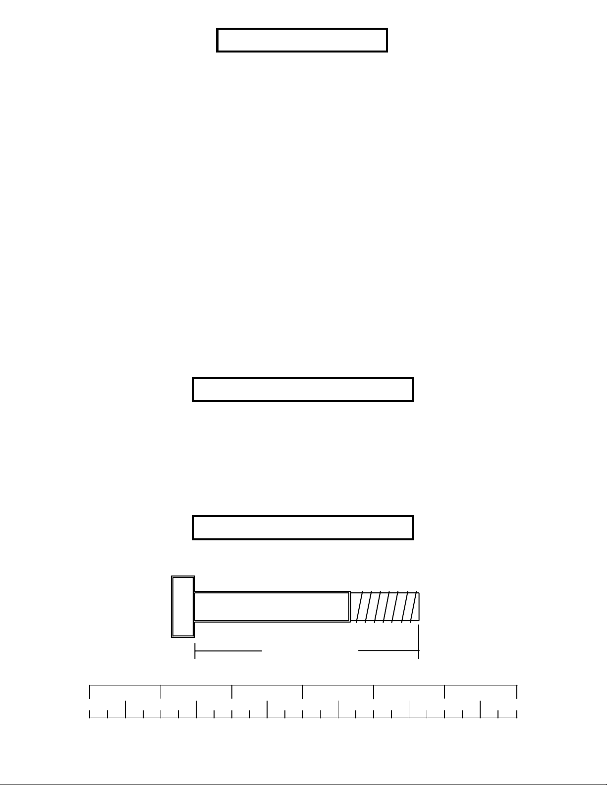
Bolt Length Ruler
NOTE: BOL T LENGTH IS MEASURED FROM THE UNDERSIDE OF THE HEAD OF THE BOLT.
BOL T LENGTH RULER:
1/2 1/2 1/2 1/2 1/2 1/2
0
1
BOLT LENGTH
2
345
2
6
Page 3

PARTS LIST
KEY
1
2
3
4
5
6
7
8
9
10
11
12
13
14
15
16
PART #
6824303
6823703
6825403
6824103
6825502
6275302
6274402
6542402
6824801
3103102
3116201
6177001
6405201
6467001
6692601
6825101
DESCRIPTION
BASE
UPRIGHT
ST AND
CROSS BRACE
CARRIAGE
LA T BAR
LOW ROW BAR
3/16 X 1-3/4 X 5-1/4” PLA TE
CABLE
1 X 8” GRIP
3-1/2” PULLEY
2-1/2 X 5-1/2” NON-SKID STRIP
2” SQ. END CAP
2” SQ COVER CAP
3 X 2” END CAP
17-1/2” FOAM STRIP
QTY
1
1
1
1
1
1
1
2
2
4
6
2
4
2
3
1
KEY
17
18
19
20
21
22
23
24
25
26
27
28
29
30
31
32
PART #
3116001
6140701
3102501
3102802
3102502
3102801
3102933
3102903
3102922
3102935
3102910
3103801
3108102
6122703
6480301
6127701
DESCRIPTION
1-1/4” RUBBER BUMPER
1 X 1” GLIDE
3/8” W ASHER
3/8” LOCK NUT
1/2” W ASHER
1/2” LOCK NUT
3/8 X 2” BOL T
3/8 X 2-1/2” BOL T
3/8 X 2-3/4” BOL T
3/8 X 4-1/2” BOL T
1/2 X 3” BOL T
5/16” SNAP LINK
1/4” QUICK DISCONNECT LINK
3/8 X 3/8” SP ACER
3/8” FLANGE SP ACER
3/8 X 1” SP ACER
QTY
1
8
12
11
2
1
2
2
6
1
1
2
1
2
6
1
3
Page 4
20
3/8 X 2-3/4” 25
14
3
13
19
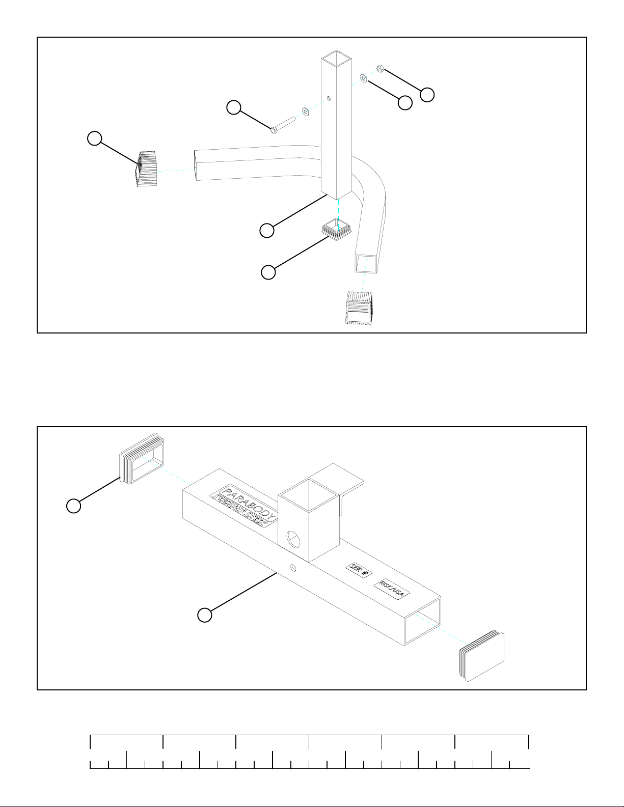
FIGURE 1
STEP 1:
• Assemble two 2” SQ. COVER CAPS (14) onto the ends of the ST AND (3) as shown in FIGURE 1.
• SECURELY assemble the one 3/8 X 2-3/4” BOL T (25), two 3/8” W ASHERS (19), and one 3/8” LOCK NUT (20) to the ST AND (3) as
shown in FIGURE 1.
• Assemble one 2” SQ. END CAP (13) into the end of the ST AND (3) as shown in FIGURE 1.
15
1
FIGURE 2
STEP 2:
• Insert two 3 X 2” END CAP (15) into the ends of the BASE (1) as shown in FIGURE 2.
1/2 1/2 1/2 1/2 1/2 1/2
0
1
2
345
4
6
Page 5
13
4
16
12
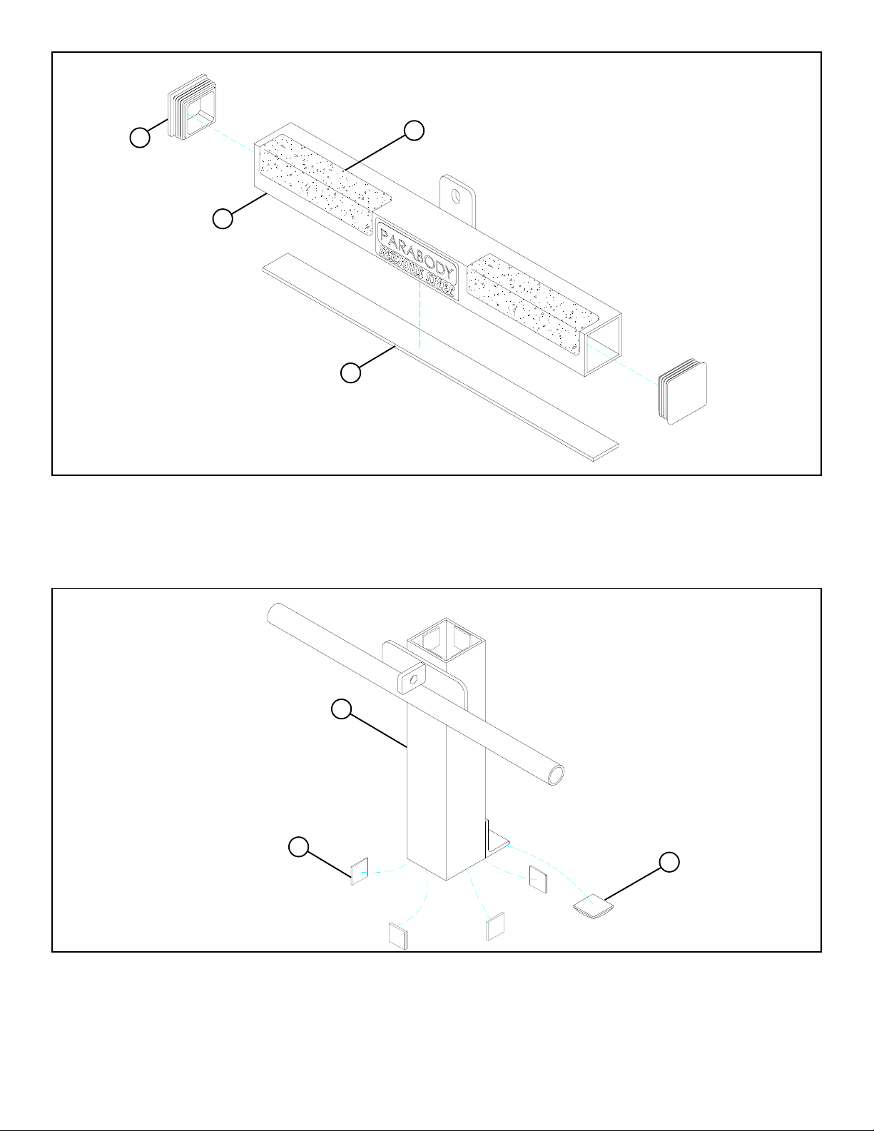
FIGURE 3
STEP 3:
• Insert two 2” SQ. END CAPS (13) into the ends of the CROSS BRACE (4) as shown in FIGURE 3.
• Assemble two 2-1/2 X 5-1/2” NON-SKID STRIPS (12) to the CROSS BRACE (4) as shown in FIGURE 3.
• Assemble one 17-1/2” FOAM STRIP (16) to the underside of the CROSS BRACE (4) as shown in FIGURE 3.
5
18
17
FIGURE 4
STEP 4:
• Attach eight 1 X 1” GLIDES (18) to the ends the CARRIAGE (5) as shown in FIGURE 4 using the following steps:
• Thoroughly clean all surfaces where the 1 X 1” GLIDES (18) are to be attached.
• Remove the 1 X 1” GLIDES (18) from the paper backing and firmly apply them to all shown surfaces.
• SECURELY attach one 1-1/4” SQ. RUBBER BUMPER (17) to the CARRIAGE (5) as shown in FIGURE 4.
5
Page 6

STEP 5:
• Assemble the STAND (3) to the UPRIGHT (2) as
shown in FIGURE 5.
• Slide the CARRIAGE (5) over the UPRIGHT (2) as
shown in FIGURE 5.
• Assemble the BASE (1) to the UPRIGHT (2) as
shown in FIGURE 5.
2
5
3
1
FIGURE 5
1/2 1/2 1/2 1/2 1/2 1/2
0
1
2
345
6
6
Page 7

13
15
2
4
3/8 X 2-3/4” 25
20
19
21
22
21
1
27 1/2 X 3”
FIGURE 6
STEP 6:
• SECUREL Y assemble the BASE (1) to the UPRIGHT (2) using one 1/2 X 3” BOLT (27), two 1/2” W ASHERS (21) (slide front washer
INSIDE of tube), and one 1/2” LOCK NUT (22). See FIGURE 6.
• Insert one 3 X 2” END CAP (15) and one 2” SQ. END CAP (13) into the ends of the UPRIGHT (2) as shown in FIGURE 6.
• SECUREL Y assemble the CROSS BRACE (4) to the UPRIGHT (2) using two 3/8 X 2-3/4” BOL TS (25), two 3/8” WASHERS (19), and two
3/8” LOCK NUTS (20). See FIGURE 6.
7
Page 8

2
20
31
9
3/8 X 2-3/4” 25
11
FIGURE 7
STEP 7:
• Route the CABLE (9) through the UPRIGHT (2) as shown in FIGURE 7.
• SECUREL Y assemble three 3-1/2” PULLEYS (1 1) into the slots of the UPRIGHT (2) using three 3/8 X 2-3/4” BOL TS (25), six 3/8” FLANGE
SP ACERS (31), and three 3/8” LOCK NUTS (20) as shown in FIGURE 7. (NOTE: Make sure the cable is r outed over all the pulleys.)
1/2 1/2 1/2 1/2 1/2 1/2
0
1
2
345
8
6
Page 9

2
20
19
11
8
9
19
23 3/8 X 2”
SECURELY
29
TIGHTEN!
5
FIGURE 8
STEP 8:
• Attach the CABLE (9) from the UPRIGHT (2) to the CARRIAGE (5) using one 1/4” QUICK LINK (29) as shown in FIGURE 8. (IMPORT ANT! Securely tighten QUICK LINK.)
• Place one 3-1/2” PULLEY (11) into the loop of the CABLE (9) below the second and third PULLEY of the UPRIGHT (2) as shown in
FIGURE 8.
• LOOSEL Y assemble two 3/16 X 1-3/4 X 5-1/4” PLA TES (8) to each side of the 3-1/2” PULLEY (11) using one 3/8 X 2” BOLT (23),
two 3/8” W ASHERS (19), and one 3/8” LOCK NUT (20). See FIGURE 8.
9
Page 10

2
20
19
20
11
30
19
8
11
9
19
23 3/8 X 2”
24 3/8 X 2-1/2”
FIGURE 9
STEP 9:
• Route the end of the second CABLE (9) through the slot on the UPRIGHT (2) then SECURELY assemble one 3-1/2” PULLEY (1 1) to
the UPRIGHT (2) using two 3/8 X 2-1/2” BOL TS (24), two 3/8 X 3/8” SP ACERS (30), four 3/8” WASHERS (19), and two 3/8” LOCK NUTS
(20). (NOTE: The CABLE (9) should be routed between the pulley and the retaining bolt as shown in FIGURE 9.)
• Loop the CABLE (9) around one 3-1/2” PULLEY (11) as shown in FIGURE 9.
• LOOSEL Y assemble the 3-1/2” PULLEY (11) to the 3/16 X 1-3/4 X 5-1/4” PLA TES (8) using one 3/8 X 2” BOL T (23), two 3/8” W ASHERS
(19), and one 3/8” LOCK NUT (20). See FIGURE 9.
• SECURELY tighten the two 3/8 X 2” BOLTS (23) of the 3/16 X 1-3/4 X 5-1/4” PLATES (8).
1/2 1/2 1/2 1/2 1/2 1/2
0
1
2
345
10
6
Page 11

9
20
1
32
26 3/8 X 4-1/2”
FIGURE 10
STEP 10:
• SECUREL Y assemble the CABLE (9) to the BASE (1) using one 3/8 X 4-1/2” BOL T (26), one 3/8 X 1” SPACER (32), and one 3/8” LOCK
NUT (20) as shown in FIGURE 10.
11
Page 12

9
10
28
6
9
28
7
10
FIGURE 11
STEP 1 1:
• Slide two 1 X 8” GRIPS (10) on the LOW ROW BAR (7) and two 1 X 8” GRIPS (10) on the LAT BAR (6) as shown in FIGURE 11.
• Attach the LAT BAR (6) to the ball end of the upper CABLE (9) using one 5/16” SNAP HOOK (28) as shown in FIGURE 11.
• Attach the LOW ROW BAR (7) to the ball end of the lower CABLE (9) using one 5/16” SNAP HOOK (28) as shown in FIGURE 11.
1/2 1/2 1/2 1/2 1/2 1/2
0
1
2
345
12
6
Page 13

3
FIGURE 12
STEP 12:
• T o use the 848101 LA T OPTION: (NOTE: LA T OPTION MUST BE USED WITH A BENCH. LA T OPTION CANNOT BE USED
WHILE STAND IS ATT ACHED. STAND MUST BE ATT ACHED WITH THE FEET OUT AS SHOWN.)
• Tilt the 848101 back and remove the ST AND (3) as shown in FIGURE 12.
13
Page 14

BENCH
2
FIGURE 13
STEP 13:
• Insert the UPRIGHT (2) of the 848101 into the bench as shown in FIGURE 13.
Thank you for purchasing the Parabody 848101 LA T OPTION. If unsur e of proper use of equipment, call
your local Parabody distributor or call the Parabody customer service department at (800) 328-9714.
14
 Loading...