

Page 1
661101 LEG PRESS ADAPTER KIT
Part #7049801
Rev . B
ASSEMBLY INSTRUCTIONS
Revision: 07/19/011
Page 2
IMPORTANT NOTES
Please note:
* Thank you for purchasing the 661 101 Leg Press Adapter Kit. Please read these
instructions thoroughly and keep them for future reference. This product must be assembled
on a flat, level surface to assure its proper function.
* We recommend cleaning your product (pads and frame) on a regular basis, using warm soapy
water. Touch-up paint can be purchased from your Parabody customer service representative
at (800) 328-9714.
There is a risk assumed by individuals who use this type of equipment. To minimize risk, please
follow these rules:
1. Inspect equipment daily . Tighten all loose connections and replace worn parts immediately.
Failure to do so may result in serious injury.
2. Do not allow minors or children to play on or around this equipment.
3. Exercise with care to avoid injury .
4. If unsure of proper use of equipment, call your local Parabody distributor or call the
Parabody customer service department at (800) 328-9714.
T ools Required for Assembly
* Rubber mallet or hammer
* 3/4” wrench
* 9/16” wrench
* Ratchet with 3/4” and 9/16” sockets
* 7/32” Allen wrench
* Adjustable wrench
* T ape measure
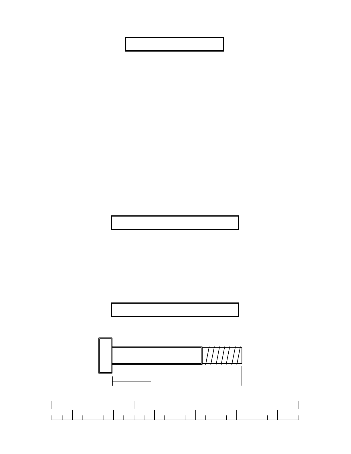
Bolt Length Ruler
NOTE: BOL T LENGTH IS MEASURED FROM THE UNDERSIDE OF THE HEAD OF THE BOLT .
BOLT LENGTH
BOL T LENGTH RULER:
1/2 1/2 1/2 1/2 1/2 1/2
0
1
2
345
2
6
Page 3
PARTS LIST
KEY
PART #
6747708
1
3116201
2
3108102
3
6427101
4
3118701
5
3201501
6
6271801
7
6747901
8
NOTE: The LEG PRESS ATTACHTMENT (100101) must be assembled before connecting it to the
3/8” X 1” BUTTON
HEAD CAP SCREW
DESCRIPTION
FRONT LEG
3-1/2” PULLEY
QUICK DISCONNECT LINK
KEYHOLE CLEVIS
2” PULLEY
SWIVEL SNAP
72”ELASTIC CORD
LEG PRESS CABLE
PARABODY 660101 HOME GYM
QTY
1
2
1
1
1
1
1
1
KEY
9
10
11
12
13
14
15
16
PART #
3102701
3102501
3102802
3102502
3102801
3102902
3102910
3102909
DESCRIPTION
3/8” HEX NUT
3/8” W ASHER
3/8” LOCKNUT
1/2” W ASHER
1/2” LOCKNUT
3/8 X 2-1/4” BOL T
1/2 X 3” BOL T
3/8 X 1”
QTY
2
3
2
4
4
2
4
1
REAR SHROUD
3/8” X 1” BUTTON
HEAD CAP SCREW
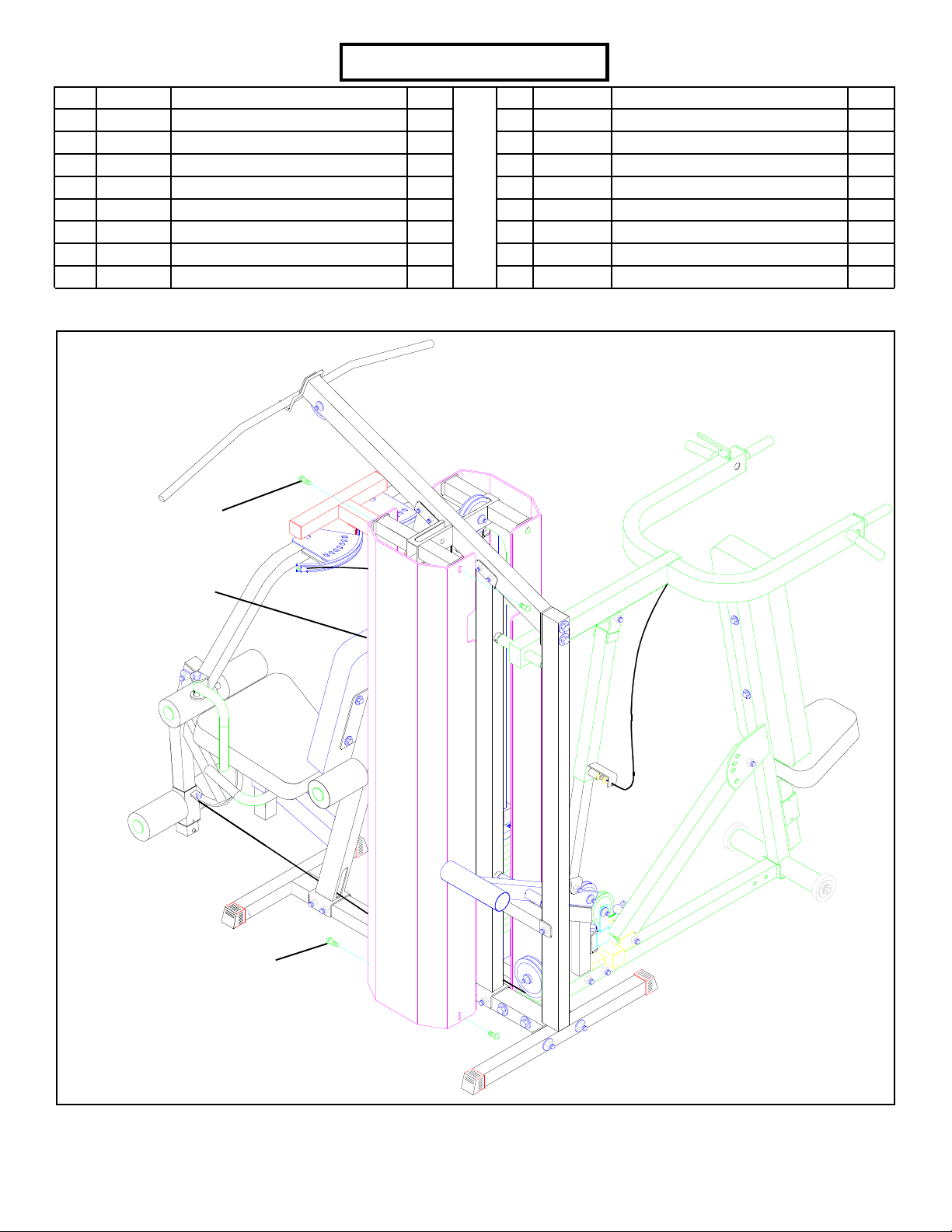
FIGURE 1
STEP 1
• REMOVE the four 3/8” X 1” BUTTON HEAD CAP SCREWS from the rear SHROUD. Remove the SHROUD from the 660101
HOME GYM. See FIGURE 1.
3
Page 4
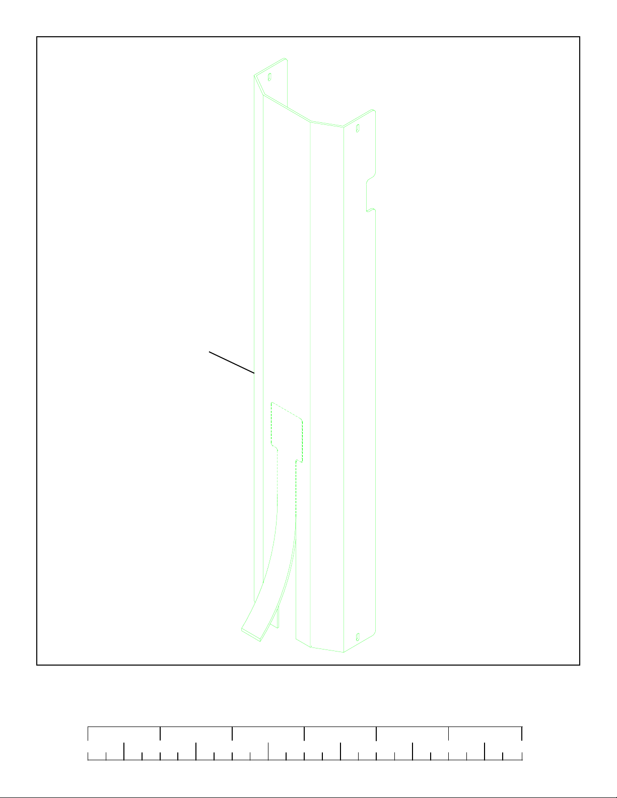
REAR
SHROUD
FIGURE 2
STEP 2
• If the 663101 SECOND STACK OPTION is not installed, the rear SHROUD opening must be removed. Apply pressure to the
bottom of the SHROUD where the “V” groove is and carefuly remove the weight stack opening on the SHROUD as shown in
FIGURE 2.
1/2 1/2 1/2 1/2 1/2 1/2
0
1
2
345
4
6
Page 5

ELASTIC CORD
3/8” LOCK NUT
SWIVEL SNAP
3/8” THREADED SHAFT
BASE
HEX NUT
3/8 X 1/2”
SP ACERS
(DISCARD)
HEX NUT
SWIVEL SNAP
3/8” LOCK NUT
FIGURE 3
STEP 3
• Remove two 3/8” LOCK NUTS, two 3/8” HEX NUTS, two SWIVEL SNAP (keep elastic cords attached), two 3/
8 X 1/2” SP ACERS, and one 3/8” THREADED SHAFT from the bracket on the BASE as shown in FIGURE 3.
• Discard the two 3/8 X 1/2” SP ACERS.
5
Page 6

FIGURE 4
3/8” LOCK NUT
3/8” THREADED SHAFT
BASE
HEX NUT
SWIVEL SNAP
2
3/8” LOCK NUT
HEX NUT
SWIVEL SNAP
STEP 4
• Assemble the two previously removed 3/8” HEX NUTS, two previously removed SWIVEL SNAPS, one 3-1/2” PULLEY (2), and two
previously removed 3/8” LOCK NUTS to the previously removed 3/8” THREADED SHAFT as shown in FIGURE 4.
3/8” X 2” BOL T
BASE
3/8” W ASHER
4-1/2” PULLEY
2-7/8” L-BRACKET
3/8” W ASHER
FIGURE 5
3/8” LOCK NUT
STEP 5
• Remove one 3/8 X 2” BOL T , two 3/8” W ASHERS, one 2-7/8” L-BRACKET, one 4-1/2” PULLEY , and one 3/8” LOCK NUT from the
upper flat on the BASE as shown in FIGURE 5.
1/2 1/2 1/2 1/2 1/2 1/2
0
1
2
345
6
6
Page 7

3/8” W ASHER
FIGURE 6
BASE
6
14 3/8 X 2-1/4”
3/8” W ASHER
4-1/2” PULLEY
2-7/8” L-BRACKET
9 HEX NUT
3/8” LOCK NUT
STEP 6
• SECURELY assemble the previously removed 4-1/2” PULLEY to the BASE using one 3/8 X 2-1/4” BOL T (14), two previously
removed 3/8” WASHERS, one previously removed 2-7/8” L-BRACKET, one SWIVEL SNAP (6), one 3/8” HEX NUT (9), and one
previously removed 3/8” LOCK NUT . See FIGURE 6.
TOP BOOM
9 3/8” HEX NUT
FIGURE 7A
(WITHOUT 663101
SECOND ST ACK
OPTION)
3/8” WASHER
5
3/8” LOCK NUT
STEP 7A
• If the 663101 SECOND STACK OPTION is installed follow STEP 7B .
• Remove one 3/8” W ASHER and one 3/8” LOCK NUT from the 3/8” THREADED SHAFT on the TOP BOOM.
• SECURELY assemble one 2” PULLEY (5) to the 3/8” THREADED SHAFT on the TOP BOOM using one previously installed 3/8”
W ASHER, one 3/8” HEX NUT (9) and one previously installed 3/8” LOCK NUT as shown in FIGURE 7A.
7
Page 8

3/8” X 1” 16
TOP BOOM
FIGURE 7B (WITH
10
663101 SECOND
ST ACK OPTION)
STEP 7B
• If the 663101 SECOND STACK OPTION is NOT installed proceed to STEP 8 .
• SECURELY assemble one 3/8 X 1” BOL T (16), one 3/8” WASHER (10), one 2” PULLEY (5) and one 3/8” LOCK NUT (1 1) to the
bracket on the TOP BOOM as shown in FIGURE 7B.
STEP 8
• SECURELY attach one 3-1/2” PULLEY (2) to the FRONT
LEG (1) using one 3/8 X 2-1/4” BOL T (14), two 3/8” WASHERS (10), and one 3/8” LOCK NUT (11). See FIGURE 8.
• Attach the open end of PRESS LINK CABLE (8) to the
QUICK DISCONNECT LINK (3). See FIGURE 8.
• SECURELY tighten the QUICK DISCONNECT (3) to the
tab on the FRONT LEG (1) as shown in FIGURE 8.
3/8 X 2-1/4” 14
5
2
10
11 3/8” LOCK NUT
10
1
11
SECUREL Y
FIGURE 8
1/2 1/2 1/2 1/2 1/2 1/2
0
1
2
345
8
8
3
TIGHTEN!
6
Page 9

1/2 X 3” 15
12
13
LEG PRESS
8
1
FIGURE 9
STEP 9
• SECUREL Y attach the LEG PRESS to the FRONT LEG (1) using two 1/2” X 3” BOL TS (15), two 1/2” WASHERS (12), and two 1/2”
LOCK NUTS (13). See FIGURE 9.
• Route LEG PRESS CABLE (8) around the 3-1/2” PULLEY on the LEG PRESS and UNDER the 3-1/2” PULLEY on the FRONT LEG (1)
as shown in FIGURE 9.
9
Page 10

1/2 X 3” 15
BASE
8
1
12
13
FIGURE 10
STEP 10
• SECUREL Y attach the FRONT LEG (1) to 660 BASE using two 1/2 X 3” BOL TS (15), two 1/2” WASHERS (12) and two 1/2” LOCK
NUTS (13). See FIGURE 10.
• Route LEG PRESS CABLE (8) under the 3-1/2” PULLEY on the 425 BASE as shown in FIGURE 10.
1/2 1/2 1/2 1/2 1/2 1/2
0
1
2
345
10
6
Page 11

SEE DET AIL 11
FIGURE 11
DETAIL 11
LEG
CABLE
LAT
CABLE
4
8
LEG
PRESS
CABLE
PRESS
CABLE
D-RING
STEP 1 1
• Run the LEG PRESS CABLE through the correct hole on the d-ring and attach one KEYHOLE CLEVIS to the end of the LEG PRESS
CABLE. See FIGURE 11 & DETAIL 11. (NOTE: If the 663101 SECOND STACK kit is installed, evenly space the LAT &
LEG EXT. CABLES on the D-RING)
STEP 12
• Assemble one 72” ELASTIC CORD (7) to the KEYHOLE CLEVIS (4)
as shown in FIGURE 12.
7
4
LEG PRESS CABLE
8
FIGURE 12
11
Page 12

FIGURE 12
STEP 12
TOP BOOM
5
7
8
LEG PRESS CABLE
• Assemble the 72” ELASTIC CORD (7) from the LEG PRESS CABLE (8) around the 2” PULLEY (5) in the TOP BOOM as shown in
FIGURE 12.
FIGURE 13
STEP 13
• Assemble the ELASTIC CORD(7)
from the LEG PRESS CABLE to the
corresponding SWIVEL SNAP (6) on
the BASE as shown in FIGURE 13.
BASE
7
6
12
Page 13

3/8” X 1” BUTTON
HEAD CAP SCREW
REAR SHROUD
3/8” X 1” BUTTON
SPRING PIN ADJUSTMENT
HEAD CAP SCREW
FIGURE 14
STEP 14
• SECURELY attach the four previously removed 3/8 X 1” BUTTON HEAD CAP SCREWS to the rear SHROUD. See FIGURE 14.
• The 100 LEG PRESS is equipped with a spring pin adjustment to accommodate different sized users and allow easy entry and exit
from the machine. To use, you must slightly push against the foot plates to take tension off the pin.
Thank you for purchasing the Parabody 661 101 Leg Press Adapter Kit. If unsure of pr oper use of equipment,
call your local Parabody distributor or call the Parabody customer service department at (800) 328-9714.
13
 Loading...