

¯
PBF601
Volume 2
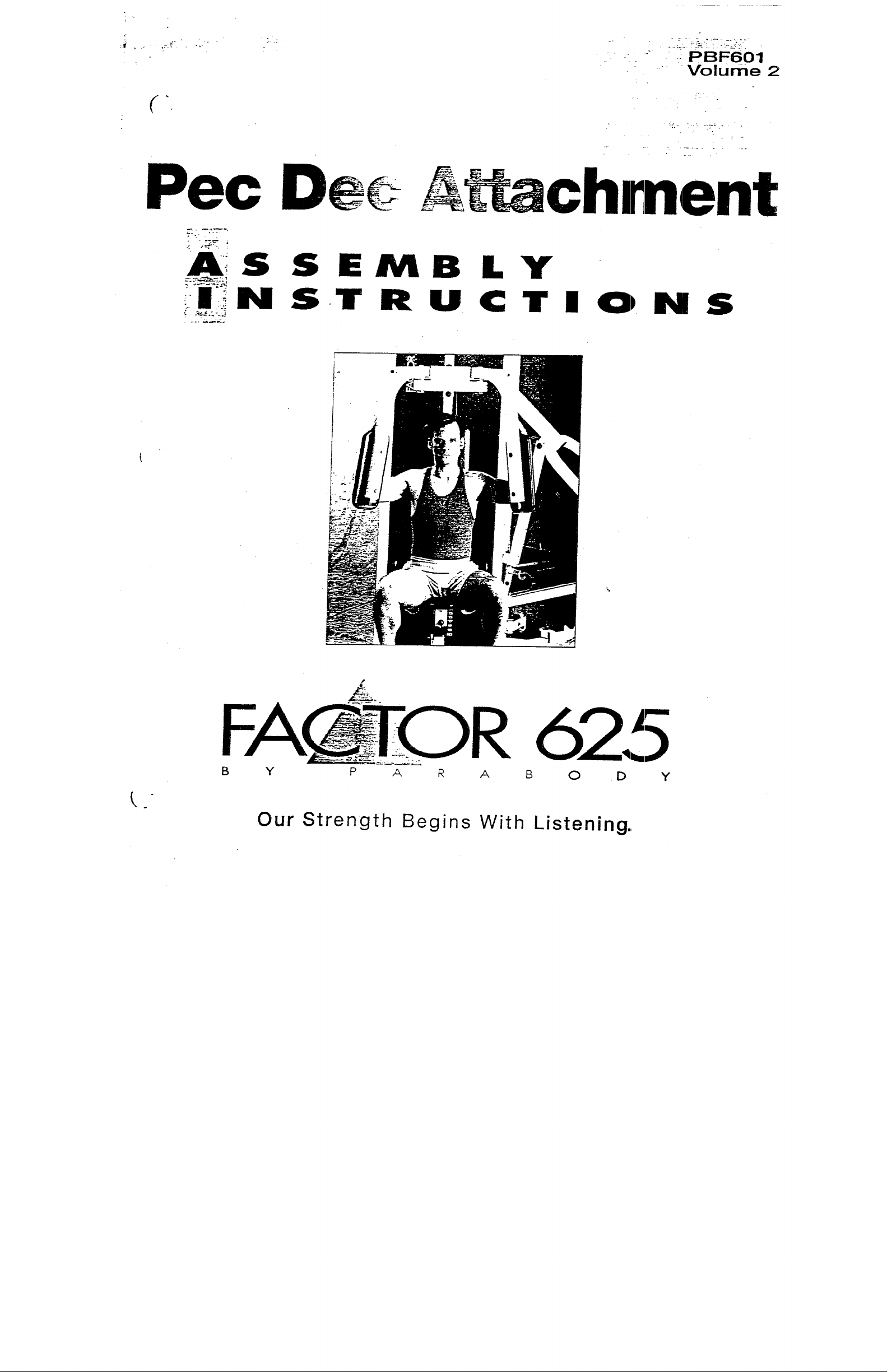
Pec
~t~achrnent
EMBLY
TRUCTIO~NS
FACTO R 62.[~
B Y P A R A B 0 .D Y
Our Strength Begins With Listening.,
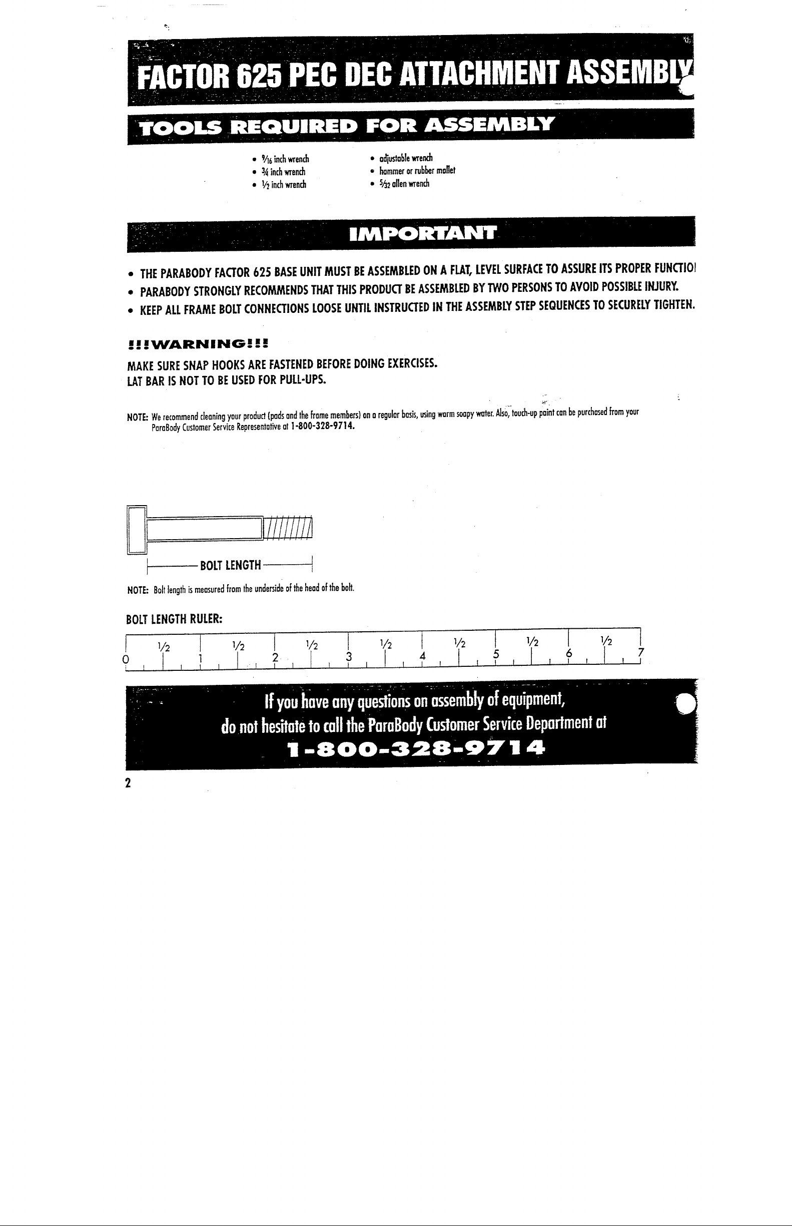
¯ 9/16 inch wrench
¯ ’~,~ inch wrench
¯ 1/2 inch wrench
¯
THE PARABODY FACTOR 625 BASE UNIT MUST BE ASSEMBLED ON A FLAT, LEVEL SURFACE TO ASSURE ITS PROPER FUNCTIOI
¯
PARABODY STRONGLY RECOI~/~ENDS THAT THIS PRODUCT BE ASSEMBLED BY TWO PERSONS TO AVOID POSSIBLE INJURY.
¯
KEEP ALL FRAME BOLT CONNECTIONS LOOSE UNTIL INSTRUCTED IN THE ASSEMBLY STEP SEQUENCES TO SECURELY TIGHTEN.
...WARNING|||
MAKE SURE SNAP HOOKS ARE FASTENED BEFORE DOING EXERCISES.
LAT BAR IS NOT TO BE USED FOR PULL-UPS.
We recommend cleaning your product (pads and the flame members) on a regular basis, using warm soapy water. Als~i’touch-up paint can be purchased from your
NOTE:
ParaBody Customer Service Representative at 1-800-328-9714.
¯ oc~ustob]e wrendz
¯ hammer or rubber ma]]et
¯ s/32 allen wrench
BOLT LENGTH
NOTE: Bolt length is measured from the underside of the head of the bolt.
BOLT LENGTH RULER:
0
¯ .~ .... ~ ....
1
2. J 3
If youhave any questions on assembly Of equipment,
do,hal hesitate to call the ParaBody Customer Service Department at
1 -800-328’9714
4
5
6
Sort and count all parts before beginning assembly.
WELDMENTS/PARTS:
ITEM NAME/DESCRIPTION
1 Kick Start
2
Pec Return (Right) (PB3270-01)
3 Pec Return (Left)
4
Pec Pulley Bracket (PB3259.01) 1
5 Pec ~m (Left)
(PB3257.01) !
(PB3269.01)
(PB3271.01) 1
6 Pec Arm (Right) "(PB3272-01)
7 Bearing Housing
(PB3266.01) 1
S~rt and count all parts before beginning assembly.
QTY.
1
1
1
ITEM NAME/DESCRIPTIOn!
8 Kick Start Cable (PB3278-01)
9
10 Pec Loop Cable
Pec Cable (PB3277-01)
(PB2518-01) 1
11 Pec Relum Cable (PB3276-01)
12 4 ~/2" Pulley w/1" (C1161-01
"
13
14
~ti-Skid 21/2" x 5]/2
E’tastic Cord 72" Lg. (PB2718-01)
(PB1770-01)
QTY.
1
1
2
7
I
1
HARDWARE:
ITEM: NAME/DESCRIPTION
BAG #1
1
2
1/~,, × 3" Bolt 3
3/8" x 3" Bolt
3 3/8" x 3/4" B01t
4 3/8"x13/4"Bolt
5 I/’2" Washer
6 3/8" Washer
7 l/2" Lock Washer
8
9
3/8" Lock Washer
I/2" Nut
10 3/8" Nut
11 1/4" Nut
12
1/~,, Lock Nut 1
13 3/8" Lock Nut
14
3,~- x 1" Oilite Bushing
15 Oilite Spacer 3~- I.D.
16 Starlock Collar 3~,"
17 Cable Retaining Clip
18 "U" Bracket
’"
~
21
~6" x I" Bait
"~ 6" Washer
~6" Lock Washer
22 -~6" Nut
QTY.
7
4
6
8
2
4
2
4
2
2
4
2
2
2
1
2
2
2
2
ITEM: NAME/DESCRIPTION
BAG #2
1
2
3
4
5
6
2" Square Cover Cap 2
1" Round White End Cap 3
Carriage Guide 1" x 1"
Elastic Cord 31/2" I.D.
1~/4" Raund End Cap 2
2"Square End Cap 4
QTY.
2
1

PEC ARM PAD
BACK PAD
PEC ARM JRIGHT)
~PB3272-01 )
PEC PULLEY BRACKET
IPB3259-01)
PEC RETURN [RIGHT~
(PB3270-O1
PEC BEARING HOUSING
(PB3266-01)
"U" BRACKET
{PB21B4-OI )
KICK START CABLE
(PB3278-01
~ PEC ARM (LEFT) KICK START
IPB3271-0)
~PB3257-01 )
PSC LOOP C.-" ~LfPB251
~EC R.:TURN (LEFT] CABLE RETAINING CUP
/PB3269-01 ~ (PB1667-01)
,. E~.ASTIC CORD
SHOCK CORD
(PB2718-01
PEC CABLE
(~3277-01)
4

’~oly lhe onli-skid 21/~" x 51zY" to the kick
p
,’~ approx, as shown.
Insert the two (2) end caps 13/4" round into
2.
each end of lhe kick start.
Attach the kick start to the lat base using one
3.
(1) I/2" x 3" bolt, four (4) V2" washers
one (1) 1/2" lock nut. Place one 1/2,, washer
on each side of lhe lal base and one 1/2"
washer on the outside of each of the flats on
the kick start (total of four (4) 1/2" washers).
Tighlen only enough to allow the kick start to
move freely.
Place one (1) 1" dia. white end cap over the
4.
bar on the front of the lot bose.
, ,
,./
/ ~’2" WASi~ER IOTY 4)
¯
]’" D!,~..VHITE END CAP
L"2" X 3" BOLT
’.~" LOCKNUT
KICK START
END CAP 1 ~ .:" RD
2 PL
/
KICK START C.~.
{PB3278-01 )
"
/
AN’rI-SKID 21/~" X 51/2"
t. Insert one (1) 2" sq. (10-14 go.) end cap
the top of the pec arm.
2.Slip one (I) cover cap 2" sq. over the bottom
end of the pec arm. The ridges on the cover
cap 2" sq. should face the pec arm pad.
3.Attach the pec arm pad to the pec arm using
two (2) 3/8"x 3" bolts and two (2)
washers and tighten. The pec arm pad should
be on the cam side of the pec arm with the
hidem clip to the bottom.
4.Repeat this procedure for the other pec arm.
COVER CAP
~.

Assemble one (1) 4V2" w/l" clevis pulley
1.
the rear pec pulley brackeI using one (1) 3~s"
× 13/4" bolt, one (1) 3I~" lock washer and one
{l) ~,;s nut.
Assemble ~’o (2) 41/2" w/1" clevis pulley
2.
the pec pulley bracket using two (2) 3/s"
13/4" bolt, two (2) cable retaining clip, two (2)
~,;~" lock washers and two (2) 3/s,, nuts.
AHach the pec pulley brackel and the pec
3.
bearing housing to the lot upright using two
(2) ;,,~" x 3" bo!ts, two (2) 1/2" washers,
(2) I/2" lock washers and no (2})/2" nuts anc]
tighten.
The large hole in each of the pec pulley
NOTE:
bracket and the pec bearing housing
should align with the large hole in the lot
upright tube with the pec pulley bracket
being closest to the weight stock side.
LAT UPRIGHT C
PEC PU ~LL:"Y BR~C.K:"T
L":" x 3~ ~DLT- 2~
WASHER - 2 ~.
LOCK WASE~:R.~ - 2 PL
NUT - 2 PL
CABL~ RETAINING CUP 2 PL
3/B’x 13/4~ BOLT- 3PL
LOCK WASH~-R - 3 PL
~/~" NUT- 3PL
REAR PEC PULLEY
BRACKET
PEC BEARING HC~SING
1.Assemble the left pec arm to the pec bearing
housing with one (1) oilite spacer 3/4" I.D., one
(1) pec return (left), two (2} 3/4" × 1"
oilite bushing and one (1) starlock collar 3/4"
(in that order)
NOTE:The 3/4" shaft on the pec arm should be
lubricated with the lube packet supplied
with your Factor 625.
See Figure 9 in the pec assembly instructions
for corred placement and orientation of the
pec return.
Repeat the above procedure for the right pec
2.
arm.
3. insert two (2) 2" sq. (10-14 ga.} end caps into
the ends of the pec bearing housing.
PEC ARM(~FT)
OIUTE SPACER .~._," LD. 2 PL
PEC RETURN (I~FT~:
~/4" I.D. x 1" O.D. C~LITE
BUSHING (QTY 2) - 2
2" SQ. x 10-14 GA. END
CAP- 2 PL
STARLOCK COLLAR
2 PL

~ - ’och the pec loop cable to the cam on each
: .c arm (route cable behind lot upright) using
one (1) s./i6" x 1" bolt, one (1) s/16" washer.
one (1)~/16" lock washer and one (1)
Route the threaded end of the pec cable under
2.
lhe weight stack from the inside of the main
frame to the outside.
Attach the threaded end of the pec cable to the
3.
"U" bracket using two (2) I/4"- 28 nuts.
(See Detail "A")
4.Route the Pec loop cable as shown and toosely
assemble one (1) 4V2" w/l" clevis pulley
the bottom of the pec loop cable using the "U"
bracket above, one (l) a/8" x 13/4" bolt, one
(1) 3/8" lock washer and one (1) 8/8"
Atlach the back pad to the lat upright using
5.
two (2) a4"x 3" bolts and two (2)
washers. The hidem clip should face down.
NOTE:The 3/~,, x 2V2" bolt used to secure the
plastic guards to the lot upright will need
to be removed from the top position.
SACK PAD
3,~"x 3" BOLT- 2PL
-".~" WASHER - 2 PL
:" W/1" CI.EViS PULLEY
LOCK WASHER
"U" BRACKET
’ °oute the kick start cable as shown with clevis
~d atlached to the kick start. (See Detail
2.Assemble the two (2) 41/2" w/l". clevis pulley
ta the lat base using one (1) 3/~" x 3" bolt,
two (2) 3/~- washers and one (1) ~4" Iocknut.
3.Route ~ick start cable and Pec cable as shown
(See Detail
AT’AC~PEC
;,","-28 NUT IOTY 2)
(SEE DETAIL "A’)
(PB3277-01)
4V2" w/1" CLEVIS PUU~Eh’
/
IOTY 2)
3/8" x 3" BOLT
WASHER {QTY 2)
LOCKNUT
KICK START CABLE
(PB3278-01)
PEC LOOP CABLE
LAT SHROUD ~ !
NEAR PULLEY ~.. I i
~.~.....~ KICK START .--:-_: .E
¯
PEC CABLE
THREADED END
PEC CABLE
FAR PUIII~

Push the two (2) pec return cables over the
1.
dowel on each of lhe pec returns.
Slip the two (2) 1" dia. white end caps over
2.
the 1" shafts on the pec returns.
Locate and stick the hvo (2) carriage guides
3.
approx, as shown.
They should prevent the pec return from
NOTE:
striking the inside of the per bearing
housing.
Slip the elastic cord ave; the 1" din. white end
4.
caps as shown. Make sure to hook the elastic
cord over the formed hook inside the pec
bearing housing.
Attach the two (2) pec return cables to the kirk
5.
start cable using one (1) 3/8" x 3/4" bolt and
one (1) 3/~-lock nut and tighten.
Route the pet/D-ring cable as shown and load
1.
into the D-ring. Add the 4|/2" w/l" clevis
pulley to the main frame using existing
hardware already installed. (see Lat Station-
figure 32.)
Tighten all loose connections at this point.
Set the elastic shack cord 72" Ig. aside until
instruded to install in the rotary assembly
instructions. (see Rotary Station
Figures 49-51.)
If the Rotary Station is already installed, attach
the elastic shock cord to the D-Ring end of the
Pec Cable, loop over the middle 2" pulley and
attach to the peg at the base alongside the
Multi-Press and Rotary shock cords. Make sure
shock cords are not touching one another.
PEC CABLE
IPB3277-0 i
LAT ~ABL~
(PB3233-01
~.
4~/2" W/1
PULLEY
CORD 31,,~" I.D.
PEC RETURN CABLE - 2 ~
(PE,3276-01
{P~3278-01)
CLEVIS
Your unit should be assembled as shown at this
point.
Proceed to the assembly instructions for the
Rotary Station.
 Loading...