

Page 1
445104 425 SECOND STACK OPTION
ASSEMBLY INSTRUCTIONS
Part # 6865201 Revision: 2/15/001
Page 2
IMPORTANT NOTES
WELCOME TO THE WORLD OF Serious steel!
Please note:
* Thank you for purchasing the Parabody 445104 Second Stack Option. Please read these
instructions thoroughly and keep them for future reference. This product must be assembled
on a flat, level surface to assure its proper function.
* We recommend cleaning your product (pads and frame) on a regular basis, using warm soapy
water. Touch-up paint can be purchased from your Parabody customer service representative
at (800) 328-9714.
There is a risk assumed by individuals who use this type of equipment. To minimize risk, please
follow these rules:
1. Inspect equipment daily . Tighten all loose connections and replace worn parts immediately.
Failure to do so may result in serious injury.
2. Do not allow minors or children to play on or around this equipment.
3. Exercise with care to avoid injury .
4. If unsure of proper use of equipment, call your local Parabody distributor or call the
Parabody customer service department at (800) 328-9714.
T ools Required for Assembly
* Rubber mallet or hammer
* 3/4” wrench
* 9/16” wrench
* Ratchet with 3/4” and 9/16” sockets
* 7/32” Allen wrench
* Adjustable wrench
* T ape measure
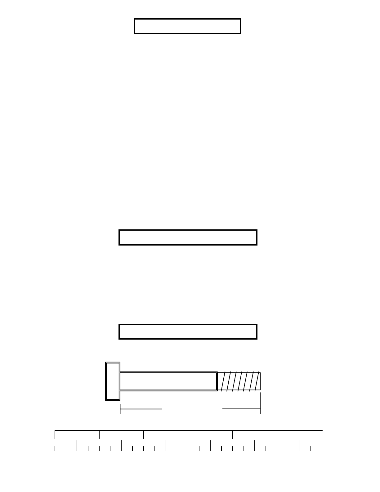
Bolt Length Ruler
NOTE: BOL T LENGTH IS MEASURED FROM THE UNDERSIDE OF THE HEAD OF THE BOLT.
BOL T LENGTH RULER:
1/2 1/2 1/2 1/2 1/2 1/2
0
1
BOLT LENGTH
2
345
2
6
Page 3
PARTS LIST
KEY
PART #
6523401
1
6266001
2
6375902
3
6714601
4
6747501
5
3116101
6
6214401
7
3108002
8
3117401
9
3102501
10
FIGURE 1
FRONT SHROUD
DESCRIPTION
GUIDE ROD
WEIGHT ST ACK SHAFT
1-1/4 SQ. X 4-7/8” TUBE
HEAD PLA TE
PRESS-ST ACK CABLE
4-1/2” PULLEY
WEIGHT ST ACK PIN
WEIGHT ST ACK CUSHION
CAP PLUG
3/8” W ASHER
QTY
2
1
2
1
1
1
1
2
4
1
KEY
11
12
13
14
15
16
17
18
19
PART #
3102909
6480301
3102922
3102901
3102503
6214501
6382301
6189501
3102802
DESCRIPTION
3/8 X 1” BOL T
3/8” FLANGE SP ACER
3/8 X 2-3/4” BOL T
3/8 X 1-1/4” BOL T
3/4” W ASHER
WEIGHT PLA TE
WEIGHT PLA TE BUSHING 10 CT .
WEIGHT ST ACK LABEL
3/8” LOCK NUT
REAR SHROUD
3/8” X 1” BUTTON
HEAD CAP SCREW
QTY
1
2
1
1
2
15
3
1
1
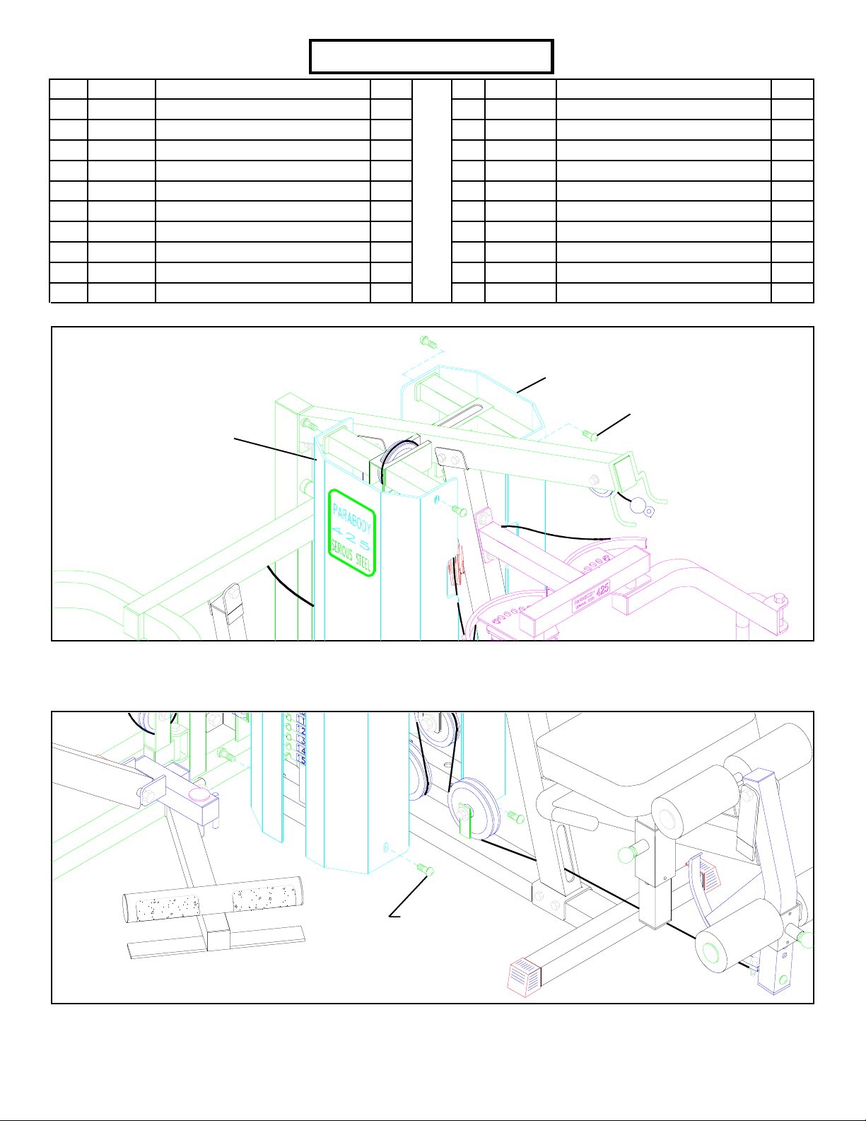
STEP 1
• REMOVE the four 3/8” X 1” BUTTON HEAD CAP SCREWS from the top of the front SHROUD & rear SHROUD. See FIGURE 1.
3/8” X 1” BUTTON
HEAD CAP SCREW
FIGURE 2
STEP 2
• REMOVE the four 3/8” X 1” BUTTON HEAD CAP SCREWS from the bottom of the front SHROUD & rear SHROUD. Remove the
SHROUDS from the 425103 HOME GYM. See FIGURE 2.
3
Page 4
HEAD
PLA TE
CABLE
(67250)
D-RING
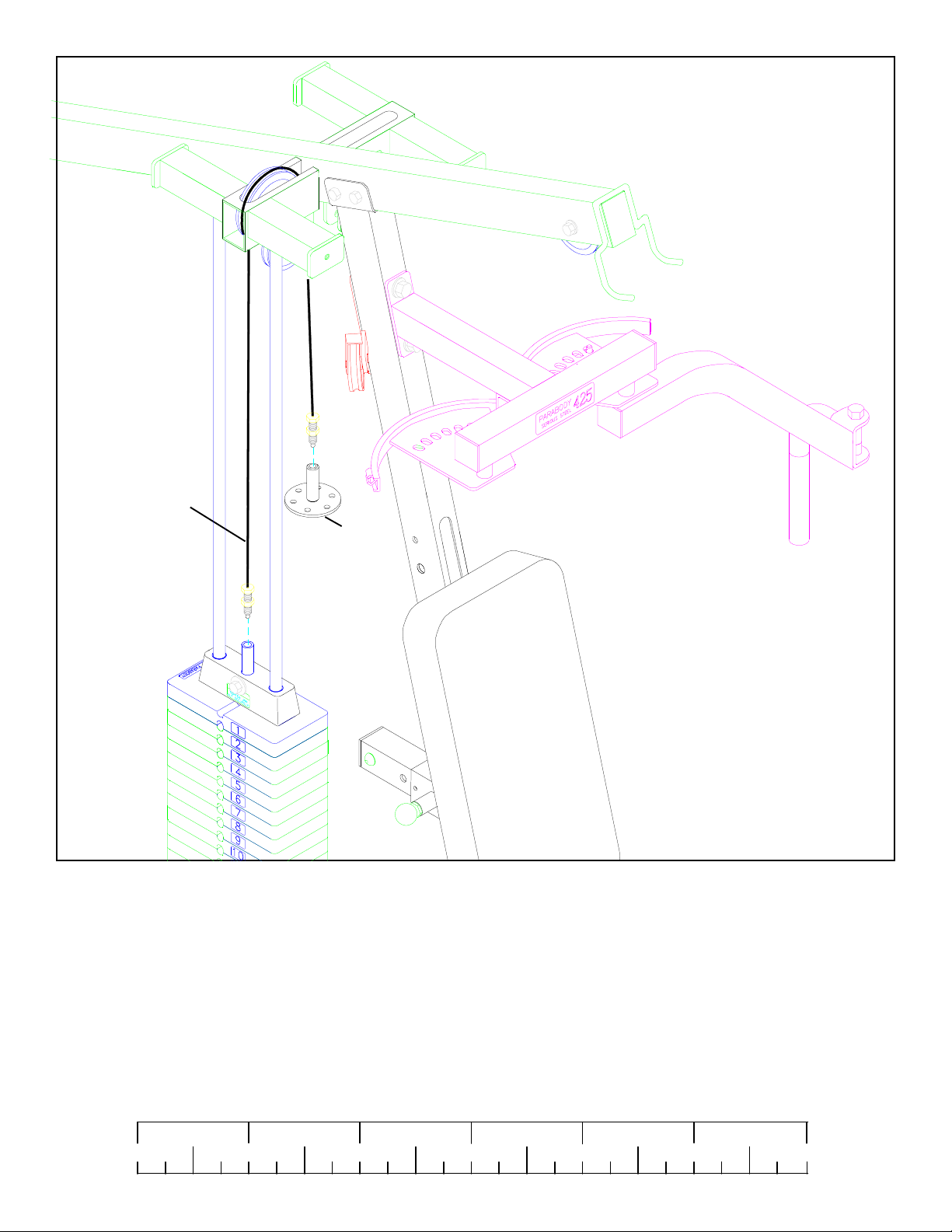
FIGURE 3
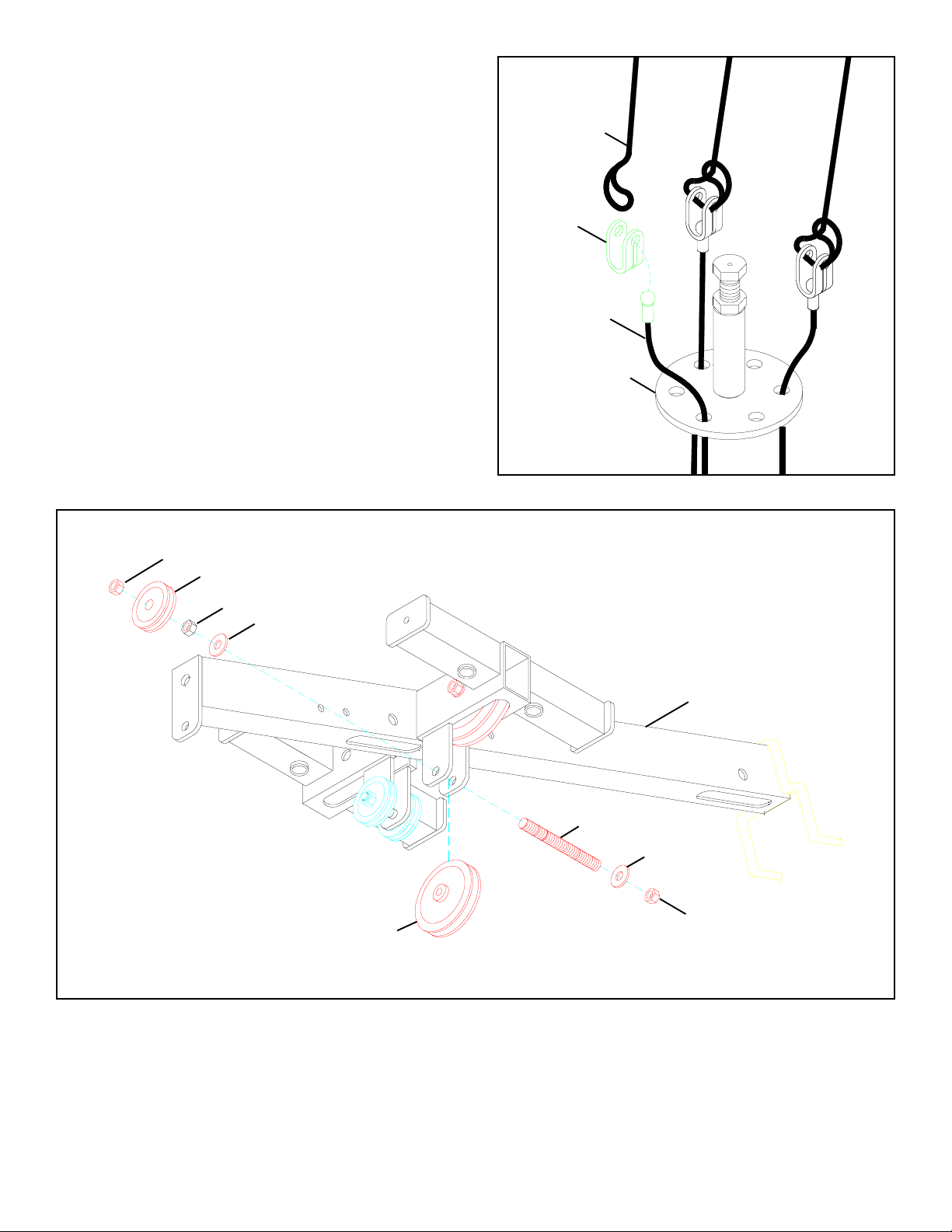
STEP 3
• Unscrew the threaded ends of the HEAD PLATE CABLE from the WEIGHT STACK SHAFT & the D-RING and remove HEAD
PLATE CABLE. The HEAD PLATE CABLE will be used later. See FIGURE 3. (NOTE: Remove pulleys for ease of removal.)
1/2 1/2 1/2 1/2 1/2 1/2
0
1
2
345
4
6
Page 5
STEP 4
• Remove the PRESS CABLE (67249) from the KEYHOLE CLEVIS
and ELASTIC CORD. (NOTE: The LA T or LEG EXT CABLE can
be moved over one hole on the D-RING so the KEYHOLE CLEVIS
are evenly spaced .)
FIGURE 4
ELASTIC
CORD
• Discard the KEYHOLE CLEVIS and ELASTIC CORD.
FIGURE 5
3/8” LOCK NUT
2” PULLEY
3/8” HEX NUT
3/8” W ASHER
KEYHOLE
CLEVIS
PRESS CABLE
(67249)
D-RING
TOP BOOM
3/8” THREADED ROD
3/8” W ASHER
3/8” LOCK NUT
3-1/2” PULLEY
STEP 5
• Remove one 3-1/2” PULLEY , one 3/8” THREADED SHAFT , two 3/8” W ASHERS, one 2” PULLEY (two if the 435104 is installed), one
3/8” HEX NUT and two 3/8” LOCK NUTS from the bracket on the TOP BOOM. See FIGURE 5.
• Discard the 3-1/2” PULLEY and the 3/8” THREADED SHAFT .
• (NOTE: If the 435101 LEG PRESS OPTION is installed proceed to STEP 6 otherwise proceed to STEP 7.)
5
Page 6

FIGURE 6
TOP BOOM
3/8” W ASHER
2” PULLEY
3/8 X 1” 11
STEP 6
• (NOTE: STEP 6 is only if the 435101 LEG PRESS OPTION is installed otherwise proceed to STEP 7.)
• Assemble the previously removed 2” PULLEY to the bracket on the TO P BOOM using one 3/8 X 1” BOL T (11), one previously removed
3/8” WASHER, and one previously removed 3/8” LOCK NUT. See FIGURE 6.
• Assemble the previously removed ELASTIC CORD over the 2” PULLEY as shown in FIGURE 6.
19
12
3/8” LOCK NUT
TOP BOOM
12
13 3/8 X 2-3/4”
6
STEP 7
• LOOSEL Y assemble one 4-1/2” PULLEY (6) to the T OP BOOM using one 3/8 X 2-3/4” BOL T (13), two 3/8” FLANGE SPACERS (12),
and one 3/8” LOCK NUT (19). See FIGURE 7.
6
FIGURE 7
Page 7

FIGURE 8
TOP BOOM
3/8” THREADED ROD
3/8” W ASHER
3/8 X 1/2” SP ACER
STEP 8
• Remove two 2” PULLEYS (5) to the rear bracket on the TOP BOOM using one 3/8” THREADED SHAFT (9), two 3/8” W ASHERS,
two 3/8” HEX NUTS (8), and two 3/8” LOCK NUTS (7) as shown in FIGURE 8.
• Discard the two 3/8 X 1/2” SP ACERS.
3/8” HEX NUT
2” PULLEY
3/8” LOCK NUT
FIGURE 9
TOP BOOM
3/8” THREADED ROD
ELASTIC
CORD
3-1/2” PULLEY
STEP 9
• SECURELY assemble the two previously removed 2” PULLEYS, one previously removed 3/8” THREADED SHAFT , one previously
removed 3-1/2” PULLEY , two previously removed 3/8” W ASHERS, two previously removed 3/8” HEX NUTS, and two previously
removed 3/8” LOCK NUTS to the rear bracket on the TOP BOOM as shown in FIGURE 9.
3/8” HEX NUT
3/8” W ASHER
2” PULLEY
3/8” LOCK NUT
• Position the elastic cords over the 2” PULLEYS as shown in FIGURE 9.
7
Page 8

FIGURE 10
PRESS CABLE
(67249)
STEP 10
• Carefully remove and discard the PRESS CABLE as shown in FIGURE 10.
1/2 1/2 1/2 1/2 1/2 1/2
0
1
2
345
8
6
Page 9

FIGURE 11
PRESS-STACK
CABLE
(67475)
PRESS-STACK
CABLE
5
(67475)
5
STEP 1 1
• Route the new PRESS-STACK CABLE (5) around the pulleys and l-brackets as shown in STEP 11. (Remove pulleys for ease of
installation.)
FIGURE 12
PRESS-
ST ACK
CABLE
(67475)
5
STEP 12
• To assemble the PRESS-STACK CABLE (5)
follow the cable routing as shown and use the
following steps:
• Route the thread end of PRESS-ST ACK CABLE (5)
up and over the PULLEY in the TOP BOOM above
the WEIGHT ST ACK. (Remove pulley for ease of
installation.)
• Screw the threaded end of the PRESS-ST ACK CABLE
(5) approximately 1” into the end of the SELECTOR
SHAFT of the HEAD PLATE on the WEIGHT
ST ACK as shown in FIGURE 12.
• SECURELY tighten the pulley connection from the
previous step.
9
Page 10

STEP 13
• Insert two WEIGHT PLATE BUSHINGS (17) into the top
side of each of the fifteen WEIGHT PLATES (16) as shown
in FIGURE 13.
FIGURE 14
17
16
FIGURE 13
LOOSEN!
TOP BOOM
LOOSEN!
STEP 14
• LOOSEN the bolts holding the TOP BOOM to the UPRIGHTS. Bolts will have to be removed to install GUIDE RODS (1). See
FIGURE 14.
1/2 1/2 1/2 1/2 1/2 1/2
0
1
2
345
10
6
Page 11

10
14 3/8 X 1-1/4”
16
7
9
1
4
2
18
BASE
8
15
3
9
FIGURE 15
STEP 15
• Insert four CAP PLUGS (9) into the top and bottom ends of the GUIDE RODS (1) as shown in FIGURE 15.
• SECURELY assemble the WEIGHT STACK SHAFT (2) to the HEAD PLATE (4) using one 3/8 X 1-1/4” BOLT (14) and one 3/8”
WASHER (10).
• Insert two GUIDE RODS (1) into the BASE as shown on FIGURE 15. (NOTE: Lubricate GUIDE RODS (1) with silicon or teflon
spray available at most hardware stores.)
• Slide two 1-1/4 SQ. X 4-7/8” TUBES (3), two 3/4” WASHERS (15), and two WEIGHT STACK CUSHIONS (8) - IN THA T
ORDER - down over the GUIDE RODS (1).
• Using EXTREME CARE slide all fifteen WEIGHT PLA TES (16) down over the GUIDE RODS (1) on to the WEIGHT ST ACK CUSHIONS
(8). Make sure that the keyholes of the WEIGHT PLATES (16) are all facing the right way. (NOTE: If the359101 50 LB. ADD-KIT is
purchased refer to the 359101 ASSEMBL Y INSTRUCTIONS now.)
• Slide the head plate assembly down over the GUIDE RODS (1) onto the weight stack.
• Attach the WEIGHT STACK LABELS (18) to the weight stack. Also insert the WEIGHT STACK PIN (7) into the first WEIGHT
PLATE (16) of the weight stack.
11
Page 12

1
TOP BOOM
TIGHTEN! (NOTE: Make sure
LAT CABLE runs over top of
bolts in TOP BOOM.)
TIGHTEN!
FIGURE 16
STEP 16
• CAREFULL Y lift or tilt the TOP BOOM and insert all GUIDE RODS into the bushings. See FIGURE 16.
• With the GUIDE RODS (1) securely held in the TOP BOOM. Tighten all TOP BOOM connections. (NOTE: Make sure the LAT
CABLE runs over the top of the bolts in the TOP BOOM.)
1/2 1/2 1/2 1/2 1/2 1/2
0
1
2
345
12
6
Page 13

STEP 17
• Screw one of the threaded ends of the previously
removed HEAD PLA TE CABLE approximately 1”
into the end of the WEIGHT ST ACK SHAFT . See
FIGURE 17.
STEP 18
• Route the thread end of HEAD PLATE CABLE up
and over the PULLEYS in the TOP BOOM above
the WEIGHT STACK. (Remove pulleys for ease
of installation.)
• Screw the other threaded end of the HEAD PLATE
CABLE approximately 1” into the end of the shaft
on the D-RING. See FIGURE 18.
FIGURE 17
HEAD PLA TE
CABLE
(67250)
WEIGHT ST ACK
SHAFT
• SECURELY tighten the pulleys connection from the previous step.
• Adjust out any slack in the two cable systems. (Refer to your 425104 instructions for the proper procedures.)
FIGURE 18
HEAD PLA TE CABLE
(67250)
D-RING
13
Page 14

REAR
SHROUD
FIGURE 19
STEP 19
• The rear SHROUD opening must be removed. Apply pressure to the bottom of the SHROUD where the “V” groove is and carefuly
remove the weight stack opening on the plastic SHROUD as shown in FIGURE 19.
1/2 1/2 1/2 1/2 1/2 1/2
0
1
2
345
14
6
Page 15

FIGURE 20
REAR SHROUD
3/8” X 1” BUTTON
FRONT SHROUD
STEP 20
• SECUREL Y attach the four previously removed 3/8” X 1” BUTT ON HEAD CAP SCREWS from the top of the front SHROUD & rear
SHROUD. See FIGURE 20.
HEAD CAP SCREW
3/8” X 1” BUTTON
HEAD CAP SCREW
FIGURE 21
STEP 21
• SECUREL Y attach the four previously removed 3/8” X 1” BUTTON HEAD CAP SCREWS from the bottom of the front SHROUD & rear
SHROUD. Remove the SHROUDS from the 425103 HOME GYM. See FIGURE 21.
• The PRESS ST ATION and SWIVEL LOW PULLEY are now operated with the front stack and the LAT, PEC, and LEG STA TION are
now operated with the rear stack.
Thank you for purchasing the Parabody 445104 Second Stack Option. If unsure of proper use of equipment,
call your local Parabody distributor or call the Parabody customer service department at (800) 328-9714.
15
 Loading...