

Page 1
l
426103 ELASTIC CORD
CONVERSION KIT
Paxt # 6860801
1
Revision: 10/12/99
Page 2
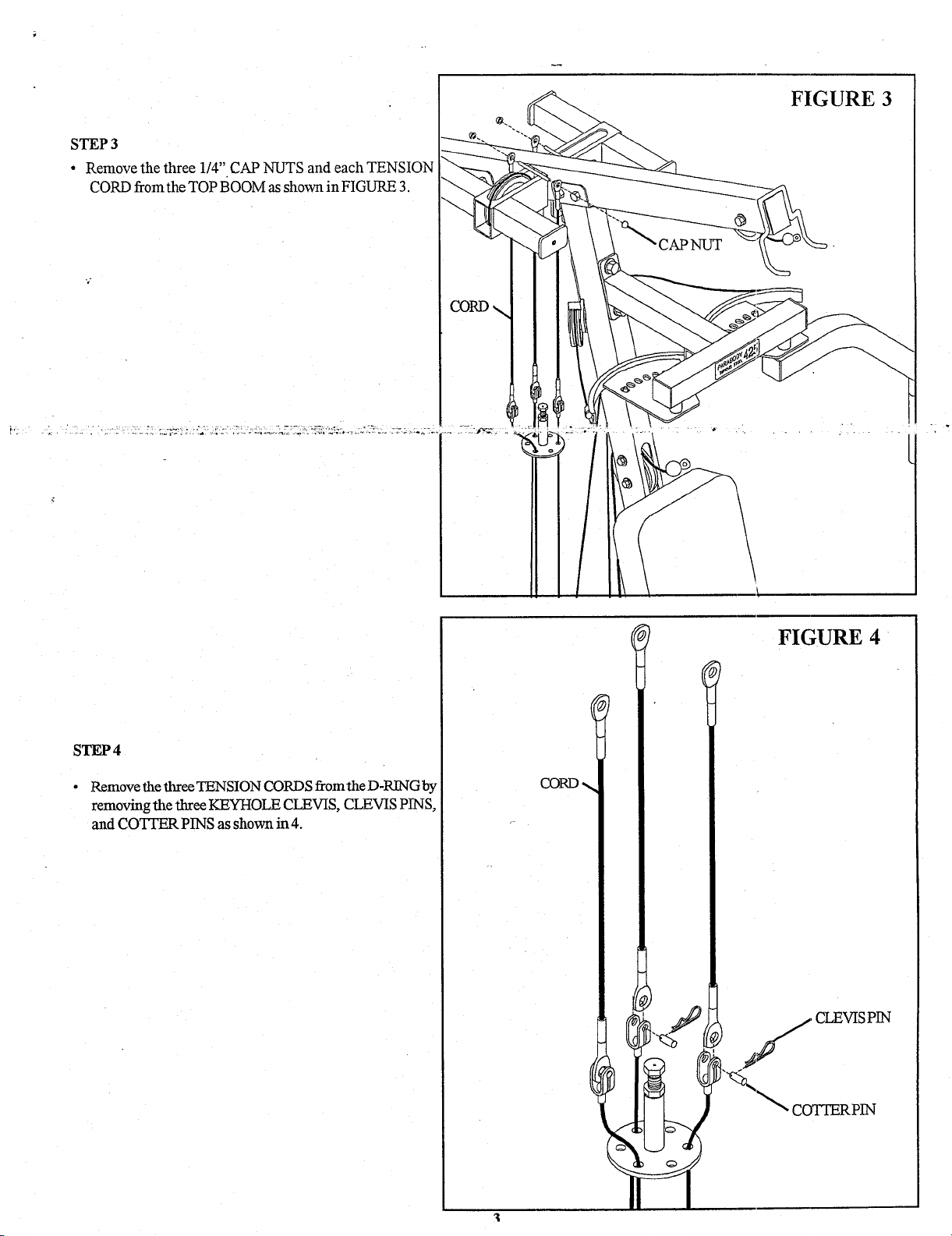
STEP 3
¯ Remove the three 1/4" CAP NUTS and each TENSION
CORD from the TOP BOOM as shown in FIGURE 3.
FIGURE 3
STEP 4
Remove the three TENSION CORDS fxom the D-RING by
removing file three KEYHOLE CLEVIS, CLEVIS PINS,
and cOTrER PINS as shown in 4.
FIGURE 4
~ CLEVIS PIN
Page 3
¯ °
4-1/2" PULLEYs/ ~
BASE
"3/8’ WASHER
....... ~ ...........
~ 2-7/8" L-BRACKET
FIGURE 5
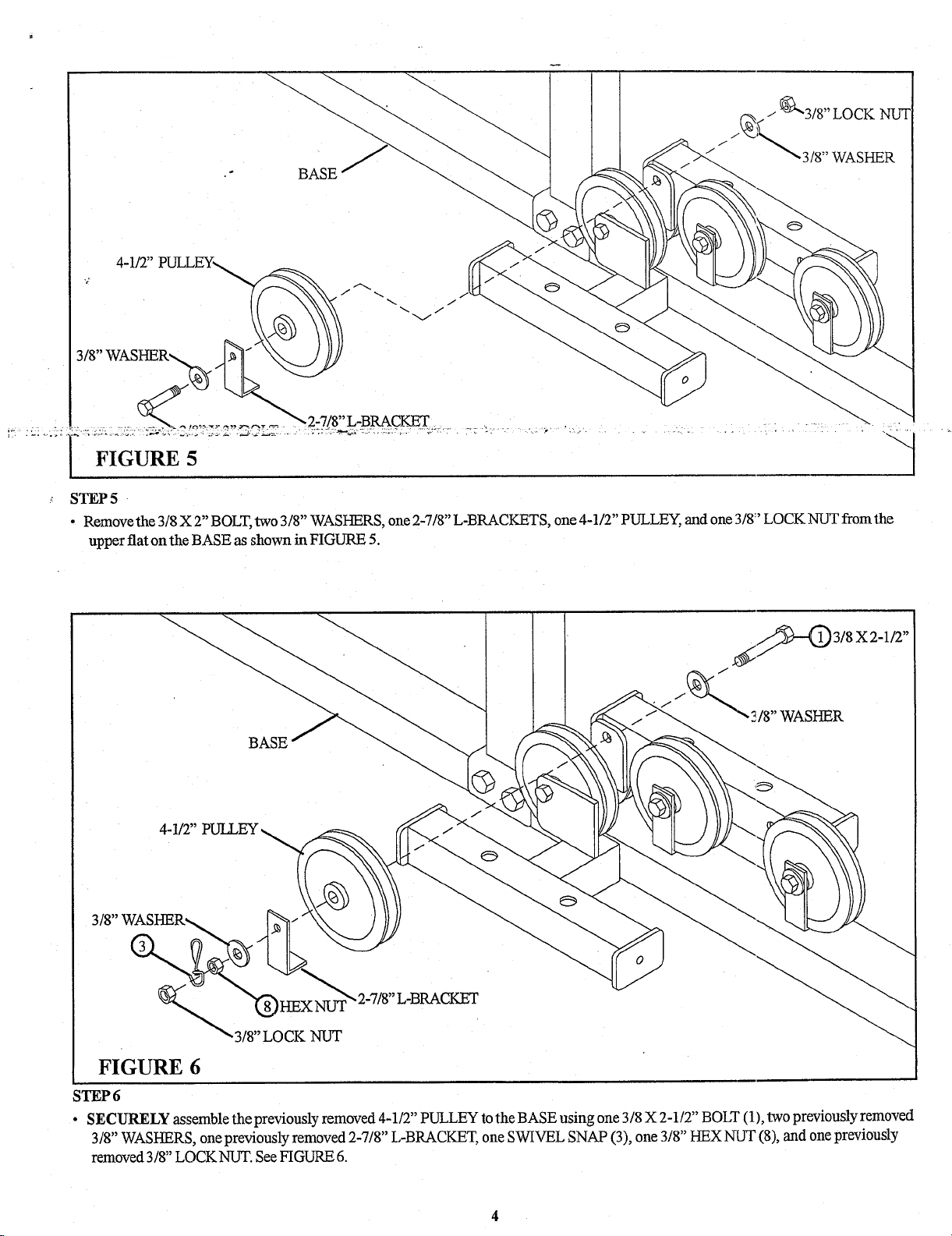
STEP 5
¯ Remove the 3/8 X 2" BOLT, two 3/8" WASHERS, one 2-7/8" L-BRACKETS, one 4-1/2" PULLEY, and one 3/8:’ LOCK NUT from the
upper flat on the BASE as shown in FIGURE 5.
18" WASHER
BASE
4-1/2"
3/8" WASHER~
FIGURE 6
;TEP 6
¯ SECURELY assemble the previously removed 4-1/2" PULLEY to the BASE using one 3/8 X 2-1/2" BOLT (1), two previously removed
3/8" WASHERS, one previously removed 2-7/8" L-BRACKET, one SWIVEL SNAP (3), one 3/8" HEX NUT (8), and one previously
removed 3/8" LOCKNUT. See FIGURE 6.
Page 4
I \
/ \
\ I
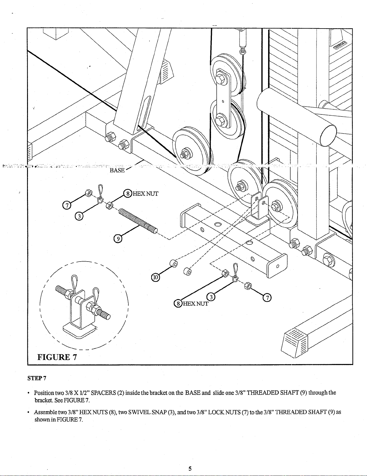
FIGURE 7
STEP7
\\
/
,/
Position two 318 X 112" SPACERS (2) inside the bracket on the BASE and slide one 318 THRE
bracket. See FIGURE 7.
Assemble two 3/8" HEX NUTS (8), t~vo SWIVEL SNAP (3), and two 3/8" LOCK NUTS (7) to the 3/8" TH]?,KM3ED SI-/A~
shown in FIGURE 7.
"
ADED
SHAFT (9) through the
Page 5
~-:- .. :-...=.-~-...-.:. ,:...._....:- .,, ...:..::.....~ .....
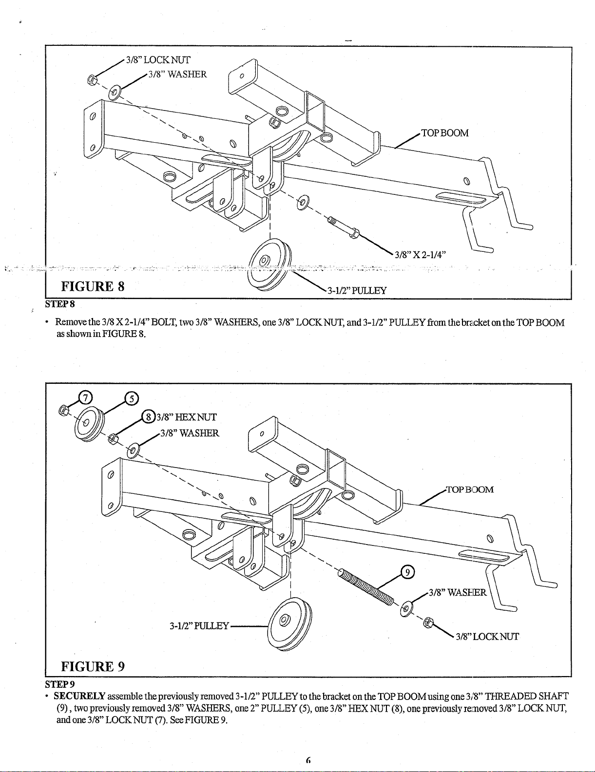
FIGURE 8
STEP 8
¯
Remove the 3/8 X 2-1/4" BOLT, two 3/8" WASHERS, one 3/8" LOCK NUT, and 3-1/2" PULLEY from the br~cket on the TOP BOOM
as shown in FIGURE 8.
~ 3/8" X 2~1/4"
~
.. ::~.-,=.~.:~:~}/~:.::.~-o-._.~..-..:-:.:’.~:-~.. .....
FIGURE 9
ITEP 9
¯ SECURELY assemble the previously removed 3-1/2" PULLEY to the bracket on the TOP BOOM using one 3/8" THREADED SHAFT
(9), two previously removed 3/8" WASHERS, one 2" PULLEY (5), one 3/8" HEX NUT (8), one previously re~.aoved 3/8" LOCK
and one 3/8" LOCK NUT (7). See FIGURE
Page 6
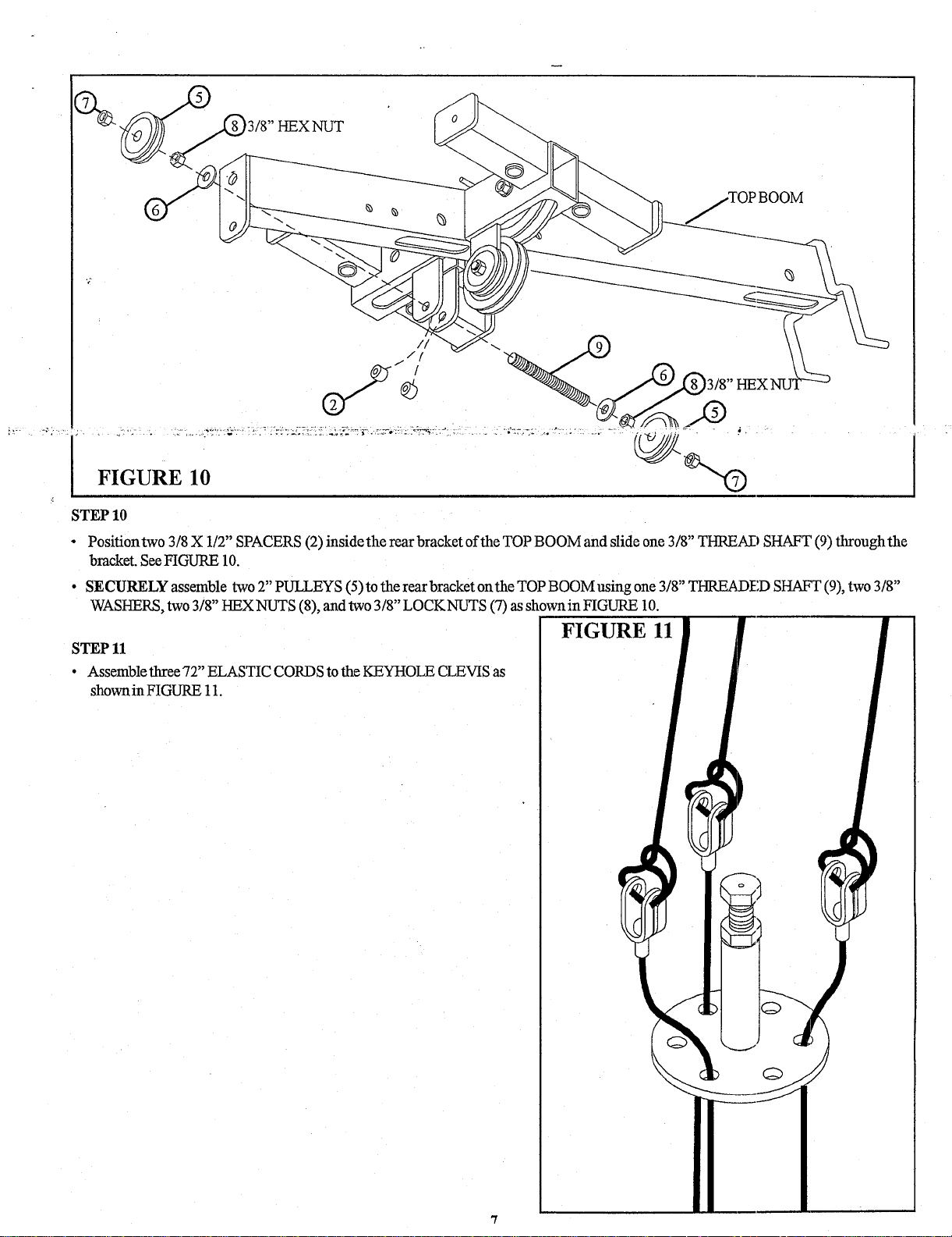
STEP 10
¯
Positiontwo 3/8 X 1/T’ SPACERS (2) inside the rear bracket of the TOP BOOM and slide one 3/8" THREAD SHAFT (9) through
bracket. See FIGLrRE 10.
¯ SECURELY assemble two T’ PULLEYS (5) to the rear bracket onthe TOP BOOM using one 3/8" THREADED SHAFT (9), two
WASHERS, two 3/8" HEXNUTS (8), and two 3/8" LOCKNUTS (7) as shownin FIGURE
FIGURE 11
STEP 11
¯ Assemble three 72" ELASTIC CORDS to the KEYHOLE CLEVIS as
shownin FIGURE 11.
Page 7
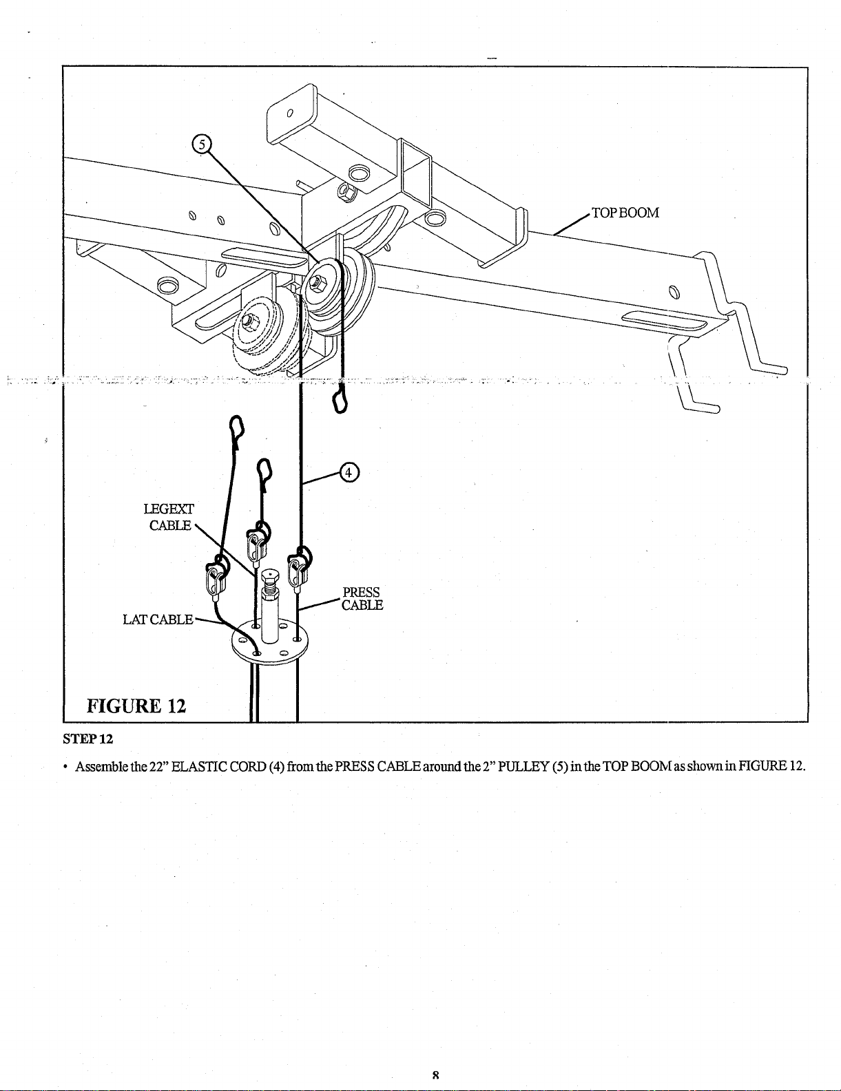
TOP BOOM
STEP 12
¯ Assemble the 22" ELASTIC CORD (4) from the PRESS CABLE around the 2" PULLEY (5) in the TOP BOON[ as shown in FIGURE
Page 8
LATq
TOP BOOM
LEGEXT
PRESS
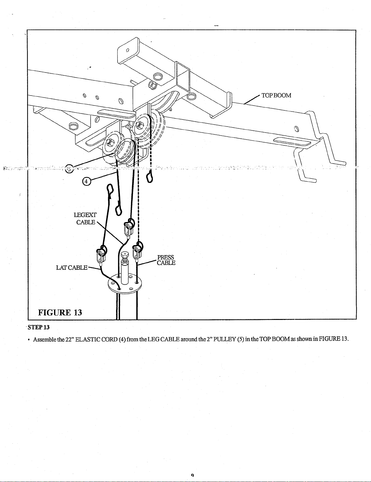
FIGURE 13
-STEP 13
¯ Assemble the 22" ELASTIC CORD (4) from the LEG CABLE around the 2" PULLEY (5) in the TOP BOOM as shown in FIGURE
Page 9
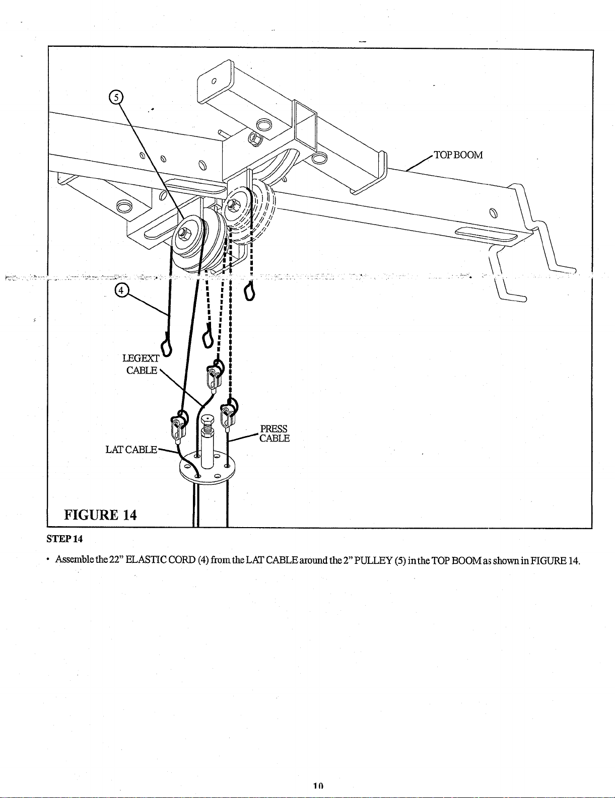
FIGURE 14
STEP 14
q
LEGEXT
LAT(
|
|
|
|
PRESS
¯ Assemble the 22" ELASTIC CORD (4) from the LAT CABLE around the 2" PULLEY (5) in the TOP BOOM a~ shown in FIGURE
Page 10
CABLE
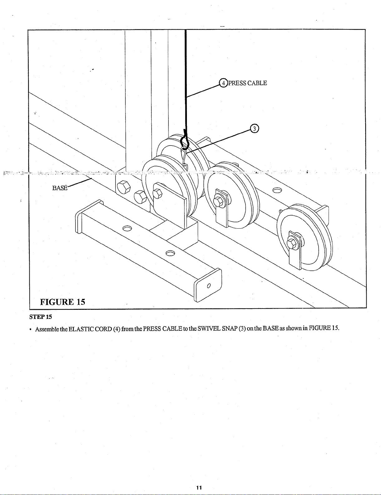
FIGURE 15
STEP 15
¯ Assemble the ELASTIC CORD (4) from the PRESS CABLE to the SWIVEL SNAP (3) on the BASE as shown in FIGURE
Page 11
BASE .
LEG CABLE
LAT CABLE
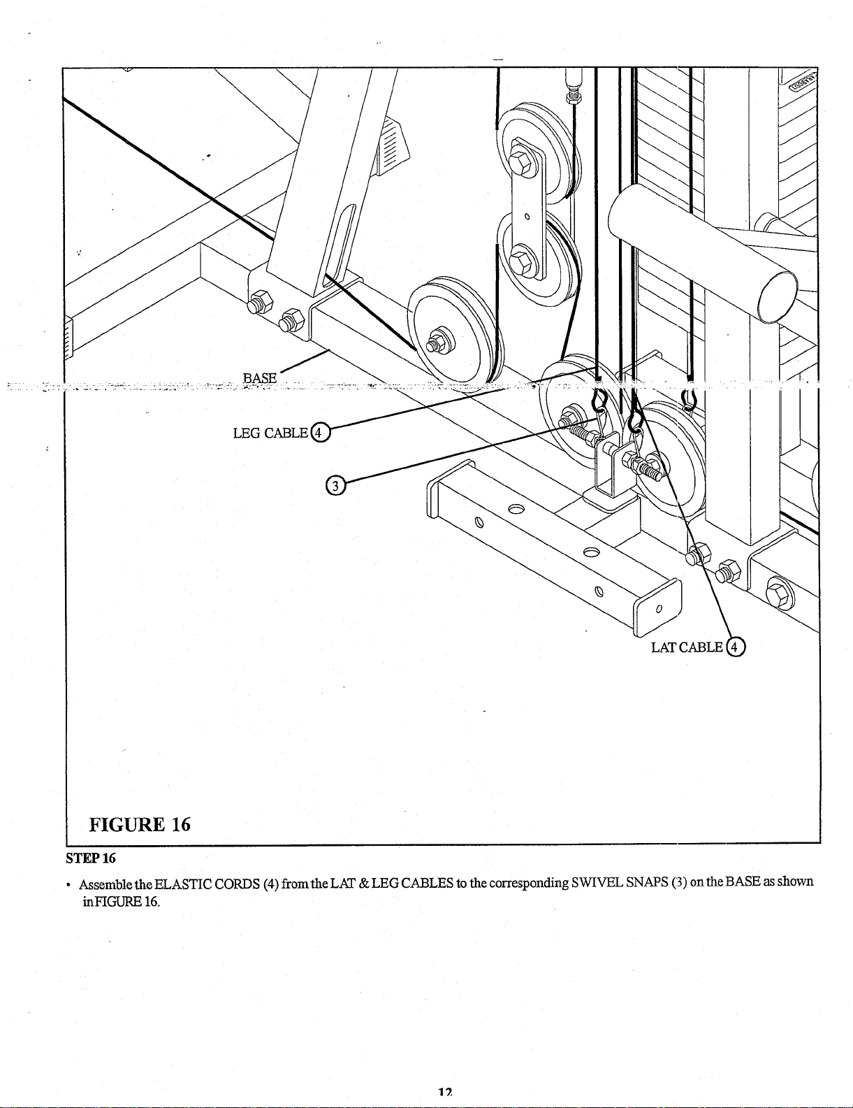
FIGURE 16
STEP 16
¯ Assemble the ELASTIC CORDS (4) from the LAT & LEG CABLES to the corresponding SWIVEL SNAPS (3) on the BASE as shown
inFIGURE 16.
Page 12
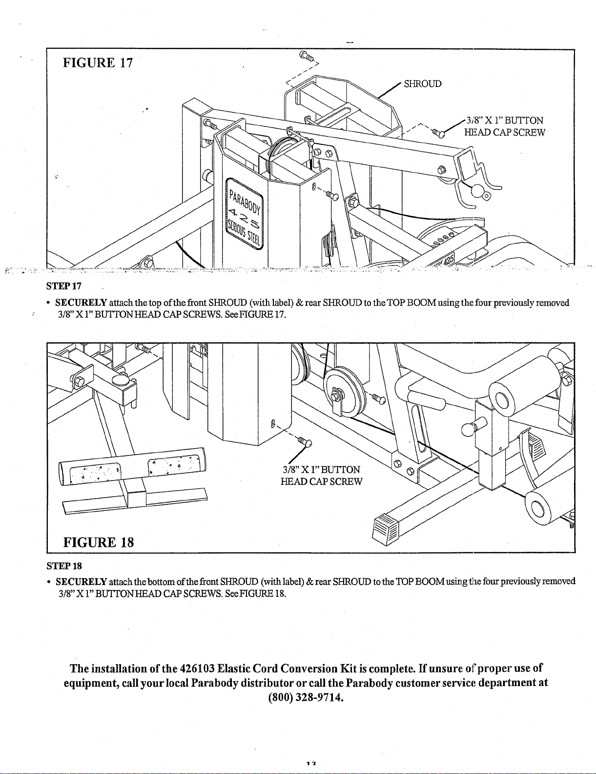
FIGURE 17
SHROUD ,
~
STEP 17
¯ SECURELY attach the top ofthe front SHROUD (with label) & rear SHROUD to the TOP BOOM using the four previously removed
3/8" X 1" BIJq~ON HEAD CAP SCREWS. See FIGURE 17.
3/8" X 1" BUTTON
FIGURE 18
STEP 18
¯ SECURELY attach the bottom of the front SHROUD (with label) & rear SHROUD to the TOP BOOM using the four previously removed
3/8" X 1" BUTTON HEAD CAP SCREWS. See FIGURE 18.
The installation of the 426103 Elastic Cord Conversion Kit is complete. If unsure or’proper use of
equipment, call your local Parabody distributor or call the Parabody customer service department at
(800) 328-9714.
Page 13
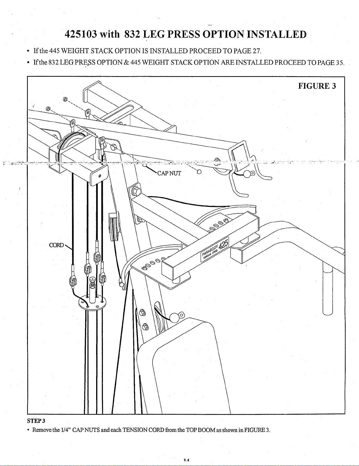
425103 with 832 LEG PRESS OPTION INSTALLED
If the 445 WEIGHT STACK OPTION IS INSTALLED PROCEED TO PAGE 27
If the 832 LEG PRESS OPTION & 445 WEIGHT STACK OPTION ARE INSTALLED PROCEED TO PAGE 35.
FIGURE 3
;TEP 3
¯ Remove the 1/4" CAP NUTS and each TENSION CORD fromthe TOP BOOM as shown in FIGURE 3.
Page 14
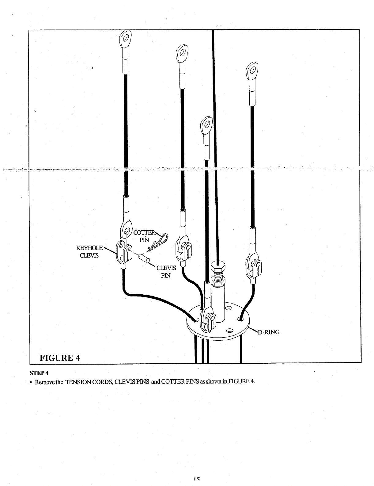
FIGURE 4
STEP 4
¯ Remove the TENSION CORDS, CLEVIS PINS and COTI’ER PINS as shown in FIGURE 4.
Page 15

3/8" LOCK NUT~
3/8" WASHER/~. / ~)
BASE
STEP 5
¯ Remove two 3/8 X 2" BOLTS, four 3/8" WASHERS, two 2-7/8" L-BRACKETS, two 4-1/2" PULLEYS, and two 3/8" LOCK NUTS from
the upper flats on the BASE as shown in FIGURE 5.
FIGURE 6
/8 X 2-1/2"
S~
BASE
.1 I~’~3/8" WASHER
"~3/a"LOCK NUT
STEP 6
¯ SECURELY assemble the previously removed 4-1/2" PULLEYS to the BASE using two 3/8 X 2-1/2" BOLTS (1), four previously
removed 3/8" WASHERS, two previously removed 2-7/8" L-BRACKETS, two SWIVEL SNAPS (3), two 3/8" HEX NUTS (8), and
previously removed 3/8" LOCK NUTS. See FIGURE 6.
Page 16

¯ ;
3/8 X 2" BOLT ~
3/8,, WASHIER ~’~’"’"-...v/
/ "~
FIGURE 7
S~P 7
Remove one 3-1/2" P~LE~ one 3/8 X 2" BOLT, two 3/8" WAS~ ~d one 3/8" LOCK ~ ~om ~e BASE ~ shown in FIG~ 7.
~/s"Loc~--
/
BASE
///~
FIGURE 8
BASE
3/8" LOCKNI~
STEP 8
¯
Assemble two 3/8" HEX NUTS (8), two SWIVEL SNAP (3), one previously removed 3-1/2" PULLEY, one previously removed
LOCK NUT, and one 3/8" LOCK NUT (7) to the 3/8" THREADED SHAFT (9) as shown in FIGURE
1’7
Page 17

STEP 9
¯
Remove the 3/8 X 2-1/4" BOLT, two 3/8" WASHERS, one 3/8" LOCK NUT, and 3-1/2" PULLEY from the bracket on the TOP BOOM
as shown in FIGURE 9.
t3/8" HEXNUT
3-1/2" PULLEY
3/8"
3/8" LOCKNUT
FIGURE 10
STEP 10
¯ SECURELY assemble the previously removed 3-1/2" PULLEY to the bracket on the TOP BOOM using one 3/8" THREADED SHAFT
(9), two previously removed 3/8" WASHERS, two 2" PULLEYS (5), two 3/8" HEX NUTS (8), one previously removed 3/8"
NUT, and one 3/8" LOCKNUT (7). See FIGURE 10.
Page 18

STEP 11
¯
Positiontwo 3/8 X 1/2" SPACERS (2) inside the rear bracket of the TOP BOOM and slide one 3/8" THREAD SHAFT (9) throughthe
bracket. See FIGURE 11.
¯ SECURELY assemble two 2" PULLEYS (5) to the rear bracket onthe TOP BOOMusing one 3/8" THREADF!D SHAFT (9), two
WASHERS, two 3/8" HEX NUTS (8), and two 3/8" LOCK NUTS (7) as shownin FIGURE
FIGURE 12
DETAIL 12
KEYHOLE
~
CABLE
CABLE ~
CABLE
LAT
CABLE
STEP 12
¯ Run th~ LEG PRESS CABLE through the correct hole on the d-ring and attach one KEYHOLE CLEVIS to the end of the LEG PRESS
CABLE. See FIGURE 12 & DETAIL 12.
19
Page 19

STEP 13
¯ Assemble four 72" ELASTIC CORDS to the KEYHOLE CLEVIS as
shown in FIGURE 13.
FIGURE 13
ELASTIC
CORD
KEYHOLE
STEP 14
Assemblethe 72" ELASTIC CORD
(4) from the PRESS CABLE around the 2" PULLEY (5) in the TOP BOO1V[ as shown in FIGURE
Page 20

LEG EXT CABLE !
~=ss
LAT CABLE
y
~,~1~ ~q.,~-----’~’~~LeGP~SS
FIGURE 15
STEP 15
¯ Assemble the 72" ELASTIC CORD (4) fromthe LEG PRESS CABLE around the 2" PULLEY (5) inthe TOP 13OOM as shown
FIGURE 15.
CABLE
CABLE
Page 21

LEGEXT
LATCABLE
TOP BOOM
--
PRESS
LEGPRESS CABLE
FIGURE 16
STEP 16
¯ Assemble the 72" ELASTIC CORD (4) from the LEG EXT CABLE around the 2" PULLEY (5) in the TOP BOOM as shownin FIGURE
22
Page 22

LAT CABLE
,
STEP 17
¯ Assemble the 72" ELASTIC CORD (4) fromtheLAT CABLE amundthe 2" PULLEY (5) inthe TOP BOOM as shovalin FIGURE
~Al~LE
Page 23

PRESS
/CABLE
LEGPRESS
CABLE
STEP 18
¯ Assemble the ELASTIC CORDS (4) from the PRESS CABLE and the LEG PRESS CABLE to the correspond~.~g SWIVEL SNAPS (3)
onthe BASE as shownin FIGURE 18.
24
Page 24

FIGURE 19
LEG CABLE ~
LAT CABLE
STEP 19
¯ Assemble the ELASTIC CORDS (4) from the LAT & LEG CABLES to the corresponding SWIVEL SNAPS (3) on the BASE as shown
inFIGURE 19.
Page 25

FIGURE 20
SHROUD
/,.3/8" X 1" BUTTON
¯ /~"~j-" HEAO cAP SCREW
STEP 20
¯ SECURELYattachthetop ofthe front SHROUD (withlabel)&rearSHROUDtotheTOPBOOMusingthefourpreviouslyremoved
3/8" X 1" BuTroN HEAD CAP SCREWS. See FIGURE 20.
3/8" X 1" BUTFON
HEAD CAP SCREW
FIGURE 21
STEP 21
¯ SECURELY attach the bottom of the from SHROUD (with label) & rear SHROUD to the TOP BOOM using th,~ four previously removed
3/8" X 1" BUTTON HEAD CAP SCREWS. See FIGURE 20.
The installation of the 426103 Elastic Cord Conversion Kit is complete. If unsure of proper use of
equipment, call your local Parabody distributor or call the Parabody customer service department at
(800) 328-9714.
Page 26

425103 with 445 WEIGHT STACK OPTION
If the 832 LEG PRESS OPTION & 445 WEIGHT STACK OPTION ARE INSTALLED PROCEED TO PAGE 35.
FIGURE 3
STEP 3
¯ Remove the 1/4" CAP NUTS and each TENSION CORD from the TOP BOOM as shown in FIGURE 3,
Page 27

LAT CABLE
(67248)
FIGURE 4
STEP 4
¯ CAREFULLY remove the TENSION CORDS by pulling the COTFERPI]q and CLEVIS PIN from the KEYHOLE CLEVIS as shown in
FIGURE4.
¯ Please discard the previously removed PRESS TENSION CORDS, COTTERPINS and CLEVIS PINS.
Page 28

BASE
FIGURE 7
STEP7
¯
Position two 3/8 X 1/2" SPACERS (2) inside the bracket on the BASE and slide one 3/8" THREADED SI-D~T (9) through
bracket. See FIGU-~ 7.
¯
Assemble two 3/8" HEX NUTS (8), two SWIVEL SNAP (3), and two 3/8" LOCK NUTS (7) to the 3/8" THI~;ADED SHAFT
shown in FIGURE 7.
Page 29

3/8 WASHER
~ ~
TOP BOOM
FIGURE 8
STEP 8
¯
Remove the 318 X 2-1/4" BOLT, two 3/8" WASHERS, one 3/8" LOCK NUT, and 3-1/2" PULLEY from the bracket on the TOP BOOM
as shown in FIGURE 8.
3/8" ~XNUT
,~3/8" WASHER
~..~
3-1/2" PULLEY
BOOM
FIGURE 9
STEP 9
SECURELY assemble the previously removed 3-1/2 PULLEY to the bracket on the TOP BOOM using on, 3/~" THREADED SHAFT
(9), two previously removed 3/8" WASHERS, two 2" PULLEYS (5), two 3/8" HEX NUTS (8), one previously removed 3/8"
NUT, and one 3/8" LOCK NUT (7). See FIGURE
Page 30

STEP 10
¯
Assemble Bvo 72" ELASTIC CORDS to the KEYHOLE CLEVIS as
shownin FIGURE 10. (NOTE: The LAT or LEG CABLE can be
moved over one hole onthe D-RING so the KEYItOLE CLEVIS are
evenly spaced as shown in FIGURE 10.)
FIGURE 10
ELASTIC
CORD ~
LEGEXT CABLE
FIGURE 11
STEP 11
¯ Assemble the 72" ELASTIC CORD (4) from the LAT CABLE around the 2" PULLEY (5) in the TOP BOOM as shown in FIGURE
Page 31

|
LAT CABLE
FIGURE 12
STEP 12
Assemble the 7 2" ELASTIC CORD (4) from the LEG EXT CABLE around the 2" PULLEY (5) in the TOP BOOM as shown in FIGURE
12.
Page 32

FIGURE 13
STEP 13
¯ Assemble the ELASTIC CORDS (4) from the LAT & LEG EXT CABLES to the corresponding SWIVEL SNAPS (3) on the BASE
shownin FIGURE 13.
Page 33

FIGURE 14
SHROUD
3/8" X 1" BUTTON
"~f/ I-{15,AD CAP SCREW
STEP 14
¯ SECURELY attach the top ofthefront SHROUD (with label) & rear SHROuD to the TOP BOOM using the four previously removed
3/8" X 1" BUTTON I-IEAD CAP SCREWS. See FIGURE 14.
FIGURE 15
STEP 15
¯ SECURELY attach the bottom of the front SHROUD (with label) & rear SHROUD to the TOP BOOM usin.g file four previously removed
3/8" X 1" BUTTON HEAD CAP SCREWS. See FIGURE 15.
The installation of the 426103 Elastic Cord Conversion Kit is complete. If unsure ol~proper use of
equipment, call your local Parabody distributor or call the Parabody customer service department at
(800) 328-9714.
Page 34

PARTS LIST
KEY
1
2
3
4
5
PART #
3102903 3/8 X 2-1/2" BOLT
6122702 3/8 X 1/2" SPACER
3201501
6271801 22" ELASTIC CORD
3118701 2"PULLEY
DES CRIPTION
SWIVEL SNAP
2 6
4 7
4 8
4 9
4 10
PART #
3102501 3/8" WASHER
3102802 3/8" LOCK N-tJT
3102701 3/8" HE)[ NUT
6535001 3/8" THREAI3 ED SHAb~
3102909 3/8" X 1" BOLT
DESCRIPTION
STEP 1
¯ Remove the top ofthe front SHROUD & rear SHROUD by removing the four 3/8" X 1" BUTTON HEAD CAP SCREWS. See FIGURE 1.
3/8" X 1" BUTTON
HEAD CAP SCREW
FIGURE 2
STEP 2
¯ Remove the bottom of the from SHROUD & rear SHROUD by removing the four 3/8" X 1" BUTTON HEAD CAP S CREWS. See
!IMPORTANT!
¯
IF THE 832 LEG- PI~SS OPTION IS INSTALLED PROCEED TO PAGE 14.
¯
IF THE 445 WEIGHT STACK OPTION IS INSTALLED PKOCEED TO PAGE 27.
¯
IF THE 832 LEG- PI~SS OPTION & 445 WEIGHT STACK OPTION ARE 1-NSTALLEI3 PROCEED TO
PAGE 35.
¯
IF NO OPTIONS ARE INSTALLED CONTINUE TO PAGE 3.
2
Page 35

425103 with 832 LEG PRESS OPTION
& 445 WEIGHT STACK OPTION INSTALLED
¯ If the 832 LEG P ,RESS OPTION IS INSTALLED PROCEED TO PAGE 14.
¯ If the 445 WEIGHT STACK OPTION IS INSTALLED PROCEED TO PAGE 27.
FIGURE 3 ~
STEP3
¯ Remove the 1/4" CAP NUTS and each TENSION CORD from the TOP BOOM as shown in FIGURE 3.
Page 36

FIGURE 4
STEP 4
¯ Remove the TENSION CORDS, CLEVIS PINS and COTI’EKPINS as shown in FIGURE 4.
CO~TER
PIN
PIN
Page 37

BASE
~1/2" PULLEY~
3/8" LOCK NUT~. _
3/8" WASHER/,,~
FIGURE 5
STEP 5
¯ Remove two 318 X 2" BOLTS, four 3/8" WASHERS, two 2-7/8" L-BRACKETS, two 4-1/2" PULLEYS, and two 3/8" LOCK NUTS from
the upper flats on the BASE as shown in FIGURE 5.
~3/8" X 2" BOLT
318 X 2-1/2" (~
BASE
"" "(~3/8" WASHER
./2" PULLEY
2-7/8" L-BRACKET
FIGURE 6
STEP 6
¯ SECURELY assemble the previously removed 4-1/2" PULLEYS to the BASE usingtwo 3/8 X 2-1/2" BOI,TS (1), four previously
removed 3/8" WASHERS, two previously removed 2-7/8" L-BRACKETS, two SWIVEL SNAPS (3), two 3/8" HEX NUTS (8), and
previously removed 3/8" LOCK NUTS. See FIGURE 6.
3/8" LOCK NUT
Page 38

3/8 X 2" BOLT ~
-/
3/8" WASI~R ~’"’""’-v
3/8" WASHER J
FIGURE 7
STEP 7
¯ Remove one 3-1/2" PULLEY, one 3/8 X 2" BOLT, two 3/8" WASHERS and one 3/8" LOCK NUT from the BASE as shown iIIFIGURE 7.
3/8" LOCK NUT"
7
BA
FIGURE 8
BASE
3-1/2"
I~8)HEXNUT
STEP 8
¯
Assemble two 3/8" HEX NUTS (8), two SWIVEL SNAP (3), one previously removed 3-1/2" PULLEY, one previously removed 3/8"
LOCK NUT, and one 3/8" LOCK NUT (7) to the 3/8" TKREADED SHAFT (9) as shown in FIGURE
Page 39

3/8" LOCK NUT
3/8" WASHER
~~
FIGURE 9
STEP 9
¯
Remove the 3/8 X 2-1/4" BOLT, two 3/8" WASHERS, one 3/8" LOCKNUT, and 3-1/2" PULLEY from the br~.cket on the TOP BOOM
as shownin FIGURE 9.
FIGURE 10
STEP 10
¯ SECURELY assemble the previously removed 3-1/2" PULLEY to the bracket on the TOP BOOM using one 3/8" THREADED SHAFT
(9), two previously removed 3/8" WASHERS, two 2" PULLEYS (5), two 3/8" HEX NUTS (8), one previously removed 3/8"
NUT, and one 3/8" LOCKNUT (7). See FIGURE 10.
Page 40

STEP 11
¯
SECURELY assemble one 318 X 1" BOLT (10), one 318" WASHER (6), one 2" PULLEY (5) and one 3/8" LOC’.K NUT (7) to thebracket
onthe TOP BOOM as shownin FIGURE 11.
FIGURE 12
STEP 12
¯ Assemble the 72" ELASTIC CORD (4) from the LEG PRESS CABLE around the 2" PULLEY (5) in the TO]? BOOM as shown
FIGURE 12.
Page 41

STEP 14
¯ Assemble three 72" ELASTIC CORDS to the KEYHOLE CLEVIS as
shown in FIGURE 14.
FIGURE 14
:
|
LAT~
CABLE
FIGURE 15
STEP 15
¯ Assemb~ethe22~ELASTICC~RD(4)fr~mtheLEGEXTCABLEar~undthe2~PULLEY(5)intheT~PB~Massh~wninFIGURE
Page 42

)OM
FIGURE 16
STEP 16
¯ Assemble the 72" ELASTIC CORD (4) from the LAT CABLE around the 2" PULLEY (5) in the TOP BOOM as shown in FIGURE
Page 43

LEGPRESS
CABLE
FIGURE 17
STEP 17
¯ Assemble the ELASTIC CORDS(4)fromthePRESS CABLEandtheLEGPRESSCABLEtothecoresponding SWIVEL SNAPS (3)on
the BASE as shown in FIGURE 17.
Page 44

FIGURE 18
LEG CABLE
LAT CAJ3LE
STEP 18
¯ Assemble the ELASTIC CORDS (4) from the LAT & LEG CABLES to the corresponding SWIVEL SNAPS (3) on the BASE as shown
inFIGURE 18.
Page 45

FIGURE 19
~
. .
~ SHROUD
STEP 19
¯ SECU~LY attach the top ’
3/8" X 1" of~e ~om S~O~ (wi~ label) & rear S~O~ to ~e TOP BOOM using the four previously removed
B~ON ~ C~ SCOWS. S~G~ 19.
3/8" X 1" BUTTON
HEAD CAP SCREW
FIGURE 20
STEP 20
¯ SECURELYattachthebottomofthefrontSHROUD (withlabel) &rear SHROUDtotheTOPBOOMusingthefcurpreviouslyremoved
3/8" X 1" BUTFONHEAD CAP SCREWS. See FIGURE 20.
The installation of the 426103 Elastic Cord Conversion Kit is complete. If unsure of proper use of
equipment, call your local Parabody distributor or call the Parabody customer service department at
(800) 328-9714.
"
 Loading...