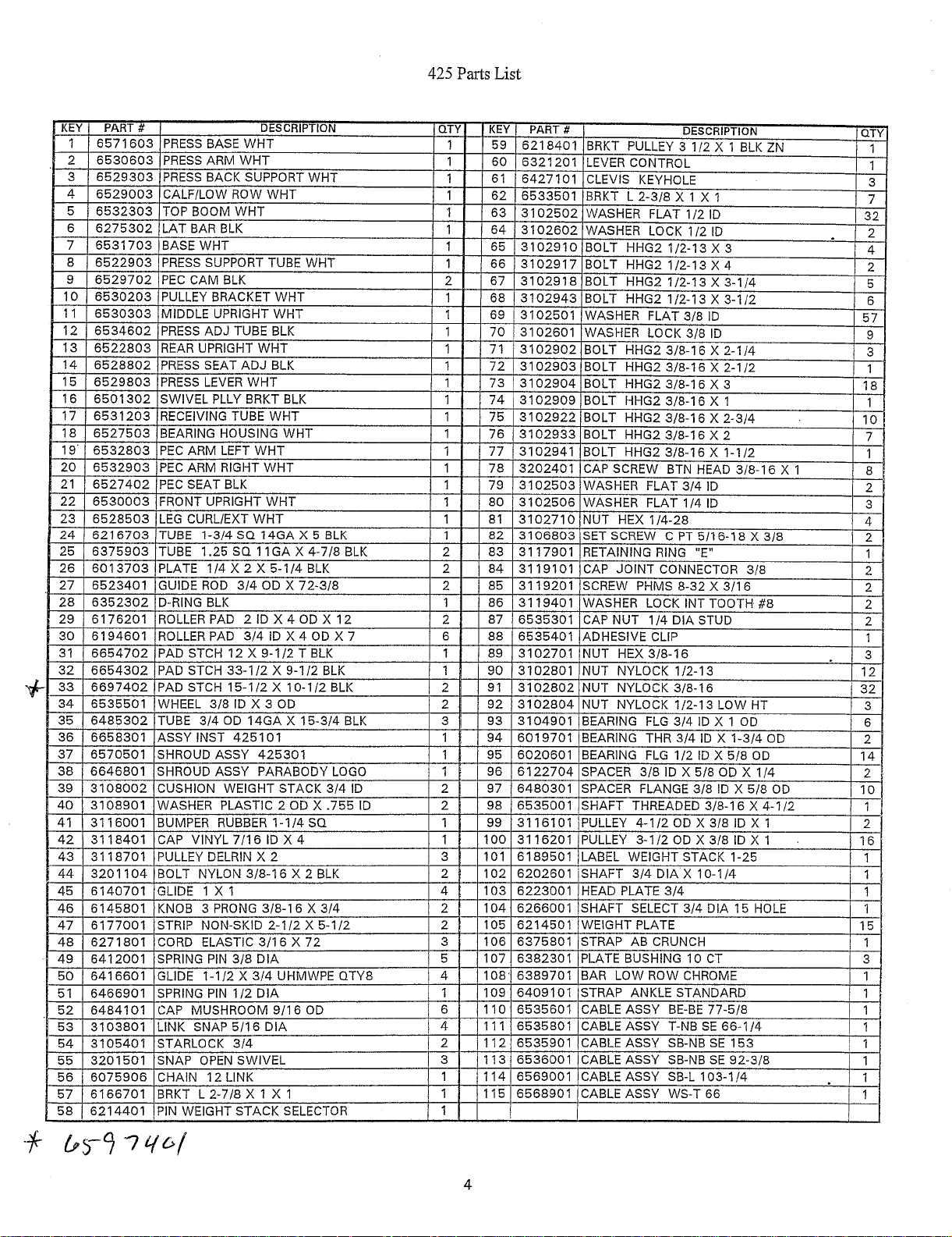
Different parts involved: Includes press arms, base, pulleys, weight stack, and cables, different parts involved.
Number of Assemblies : 112 Parts are different and unique in nature.
Method of Assembly: Fitted using bolts, washers, and lock nuts, auto cad engineering drawings classify the lengths of specific parts and bolts: Various sizes, 1/2", 3/8" and others.
Options for weight stacks: Assembled to either a 150 lb or 200 lb stack.
Pulleys: Several sizes included for other functions.
Features that can be adjusted: Adjustable press seat and arm.
Materials: Components are also made out of steel, plastics, and rubber.
Areas: Functional Areas include Press, Lat pull, Low row, Calf raise and leg curl/extend.
Frequently Asked Questions
Q1: What’s the weight limit for Serious Steel 425 Home Gym?
A1: The limit can either be set to 150 lb or 200 lb depending on the configuration and set up of the gym.
Q2: Can an average person fix the assembly manual?
A2: Indeed, it contains a comprehensive breakdown of the components and, their respective steps in order to assemble the machine in an organized and structured manner.
Q3: What kinds of workouts can I do with this home gym?
A3: You can perform multiple exercises on the Serious Steel 425 Home Gym, including pressing, rowing, leg curls, lat pull and calf raise.
Q4: Would It require extra tools or hardware to put the parts together?
A4: Everything required for the assembly is provided, and nothing else is required other than that has and will be provided.
Q5: How to go about adjusting the press seat and other components?
A5: The press seat and other accessories can be adjusted using spring pin assemblies and thumb screws as described in the manual.
User Manual
Serious Steel
425 ~~9
~
HOME GYM
ASSEMBLY INSTRUCTIONS
PART #66583011
11/18/96
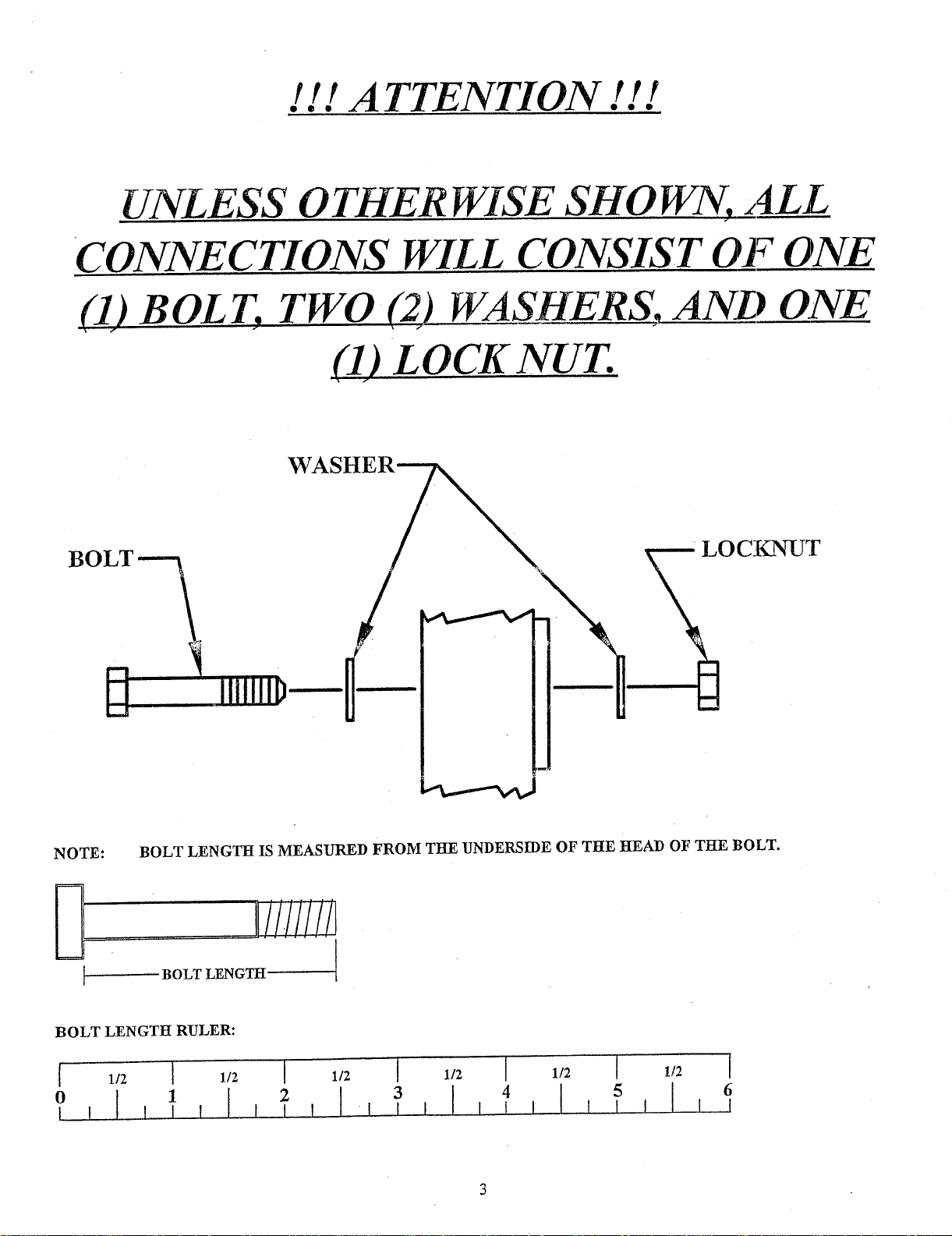
! ! ! ATTENTION ! ! !
UNL ESS 0 THER WISE SHO WN, ALL
CONNECTIONS WILL CONSIST OF ONE
(1) BOLT, TWO C) WASHERS.
(1) LOCKNUT.
BOLT
WASHER~
ONE
CKNUT
NOTE:
BOLT LENGTH RULER:
BOLT LENGTH IS MEASURED FROM THE UNDERSIDE OF THE HEAD OF THE BOLT.
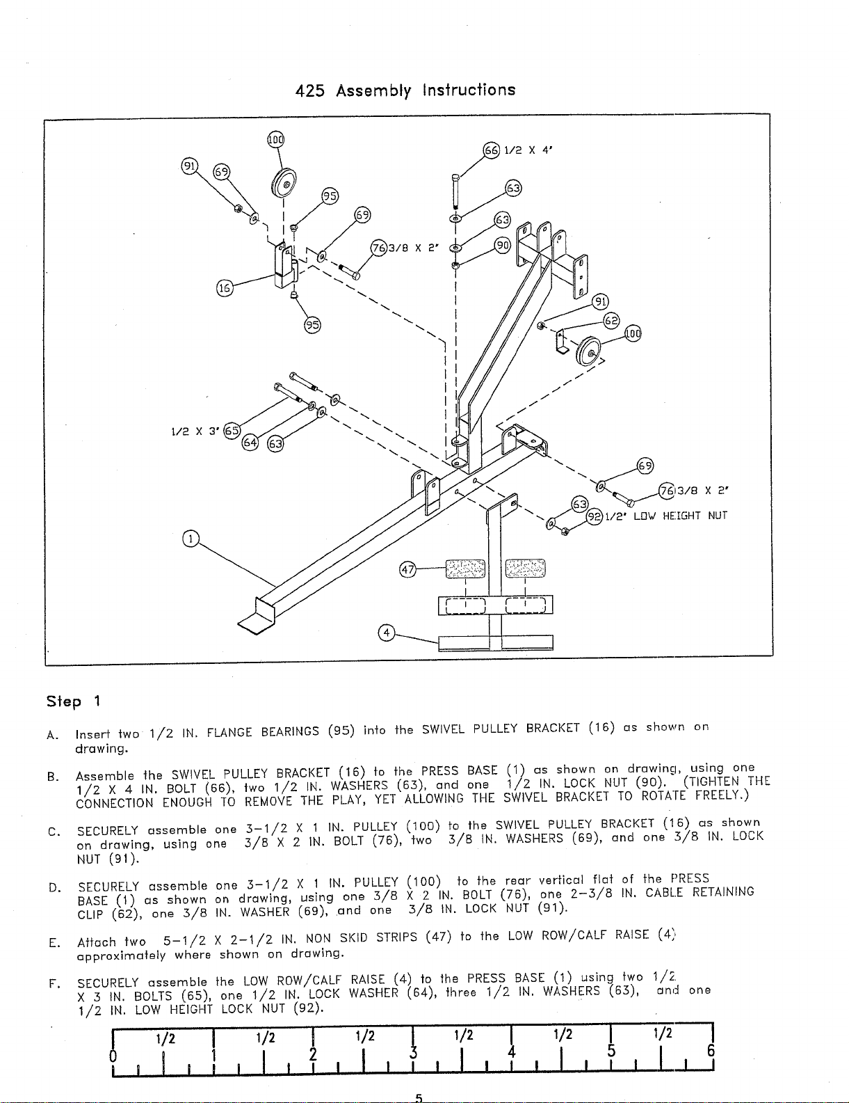
A.Insert two 1/2 IN. FLANGE BEARINGS (9.5) into the SWIVEL PULLEY BRACKET (16) os shown
drawing.
Assemble the SWIVEL PULLEY BRACKET (16) to the PRESS BASE (1) as shown on drowing, using
B.
1/2 X 4 IN. BOLT (66), two 1/2 IN. WASHERS (63), and one 1/2 IN. LOCK NUT (90). (TIGHTEN
CONNECTION ENOUGH TO REMO~E THE PLAY, YET ALLOWING THE SWIVEL BRACKET TO ROTATE FREELY.)
C.SECURELY essemble one 3-1/2 X 1 IN. PULLEY (100) to the SWIVEL PULLEY BRACKET (16) as shown
on drawing, using one 3/8 X 2 IN. BOLT (76), two 3/8 IN. WASHERS (69), and one 3/8 IN.
NUT (91).
D.SECURELY essemble one 3-1/2 X 1 IN. PULLEY (100) to the rear vertical fiat of the PRESS
BASE (1) as shown on drawing, using one 3/8 X 2 IN. BOLT (76), one 2-3/8 IN. CABLE RETAINING
CLIP (62), one .3/8 IN. WASHER (69), .and one 3/8 IN. LOCK NUT (91).
E.Attach two 5-1/2 X 2-1/2 IN. NON SKID STRIPS (47) fo the LOW ROW/CALF RAISE
approximately where shown on drawing.
SECURELY assemble the LOW ROW/CALF RAISE (4) |o the PRESS BASE (1 using two 1/2.
F.
X :5 IN. BOLTS (65), one 1/2 IN. LOCK WASHER (64), three 1/2 IN. WASHERS (65),
1/2 IN. LOW HEIGHT LOCK NUT (92).
2 I I I , ] , I , ] I I I L I ,,I1 l I I I
56
i i I I I I
end one
318 X 2-3/4"~
112 X 3-t12"
1/
I/
I/
I
//
/
/
/
/ //
/
/
/
3/8 X 2"
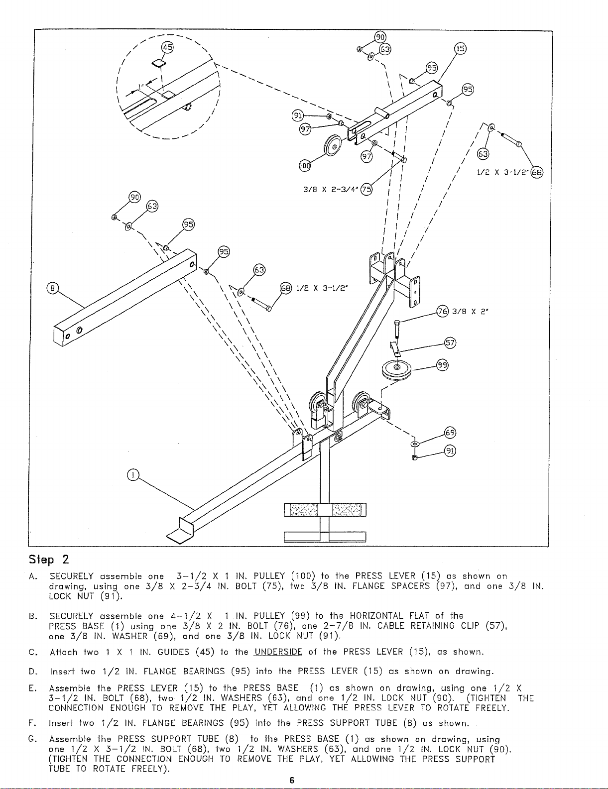
S|ep 2
A.SECURELY assemble one 3-1/2 X 1 IN. PULLEY (100) to the PRESS LEVER (15) as shown
drawing, using one 5/8 X 2-5/4 IN. BOLT (75), fwo 5/8 IN. FLANGE SPACERS (97), and one 5/8
LOCK NUT (91).
B.SECURELY assemble one 4-1/2 X 1 IN. PULLEY (99) fo the HORIZONTAL FLAT of ~he
PRESS BASE (1) using one 5/8 X 2 IN. BOLT (76), one 2-7/8 IN. CABLE RETAINING CLIP (57),
one 5/8 IN. WASHER (69), and one 5/B IN. LOCK NUT (91).
C.Aflach two 1 X 1 IN. GUIDES (45) to fhe UNDERSIDE of fhe PRESS LEVER (15), as shown.
D.Inserf two 1/2 IN. FLANGE BEARINGS (95) into fhe PRESS LEVER (15) as shown on drawing.
E.Assemble the PRESS LEVER (15) to the PRESS BASE (1) us shown on drawing, using one 1/2
5-1/2 IN. BOLT (68), two 1/2 IN. WASHERS (65), and one 1/2 IN. LOCK NUT (90). (TIGHTEN
CONNECTION ENOUGH TO REMOVE THE PLAY, YET ALLOWING THE PRESS LEVER TO ROTATE FREELY.
F.
Inserf fwo 1/2 IN. FLANGE BEARINGS (95) in|o the PRESS SUPPORT TUBE (8) as shown.
G.Assemble the PRESS SUPPORT TUBE (8)fo the PRESS BASE (1) as shown on drawing, using
one 1/2 X 5-1//2 IN. BOLT (68), fwo 1/2 IN. WASHERS (65), and one 1/2 IN. LOCK NUT (90).
(TIGHTEN THE CONNECTION ENOUGH TO REMOVE THE PLAY, YET ALLOWING THE PRESS SUPPORT
TUBE TO ROTATE FREELY).
6
o
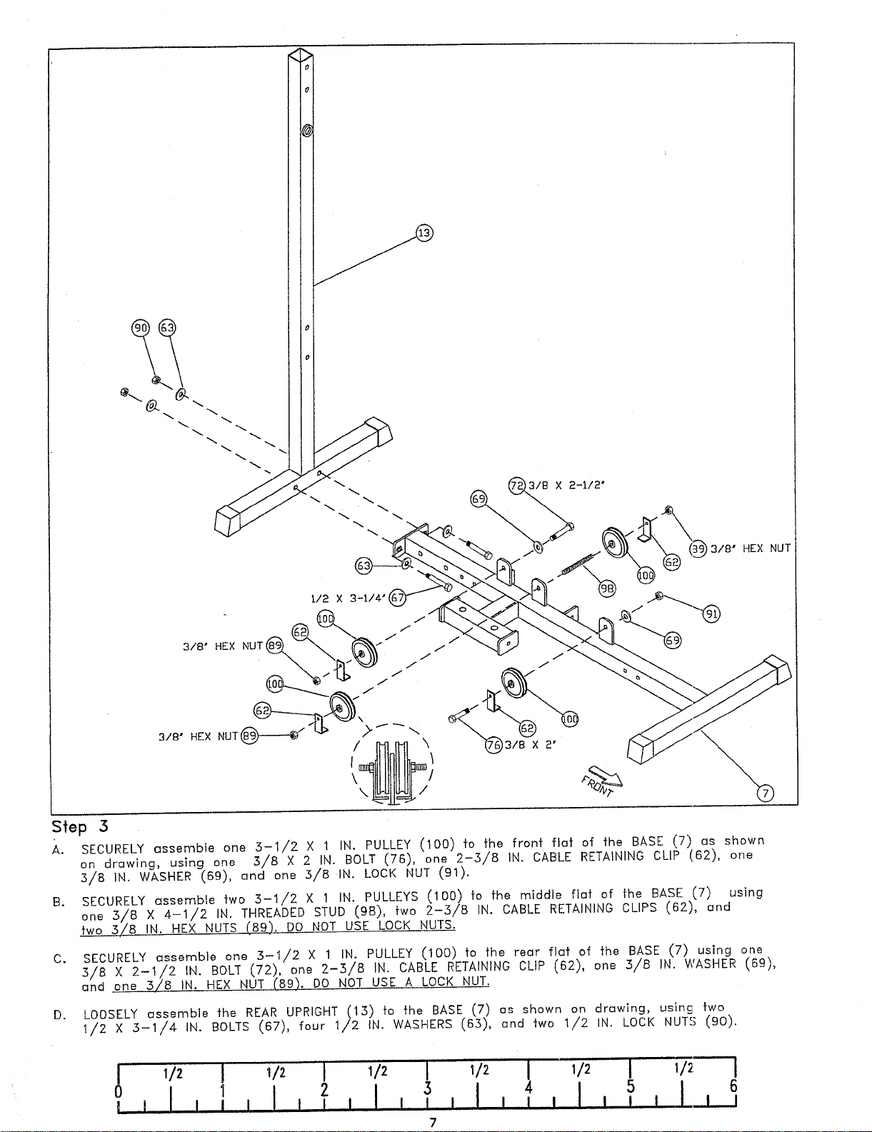
Step 3
A.SECURELY assemble one :5-1/2 × 1 IN. PULLEY (100) fo fhe fr’onf flat of -~he BASE (7) as shown
on drawing, using one 3/a × 2 IN. BOLT (76), one 2-3/a IN. CABLE RETAINING CLIP (162), one
5/8 IN. WASHER (69), and one 5/8 IN. LOCK NUT (91).
SECURELY assemble two 5-1/2 X 1 IN. PULLEYS (100) fo the middle flat of the BASE (7) using
B.
one :5/8 X 4-1/2 IN. THREADED STUD (9B), two 2-:5/8 IN. CABLE RETAINING CLIPS (62),
two 5/8 IN. HEX NUTS (89). DO NOT USE LOCK NUTS.
SECURELY assemble one 3-I/2 X 1 IN. PULLEY (100) to the rear flat of the BASE (7) using
C.
5/B X 2-1/2 IN. BOLT (72), one 2-3/8 IN. CABLE RETAINING CLIP (62), one 3/B IN. WASHER (69),
and_one 3/8 IN. HEX NUT (89). DO NOT USE A LOCK NUT.
LOOSELY assemble the REAR UPRIGHT (13) to the BASE (7) as shown on drawing, using
D.
1/2 X :5-1/4 IN. BOLTS (67), four 1/2 IN. WASHERS (63), and two 1/2 IN. LOCK NUTS (90).
1/2
I
1
’I
1/2
II
4
I I ! II ~ I~
7
I i iI L! I
I
5
’i
6
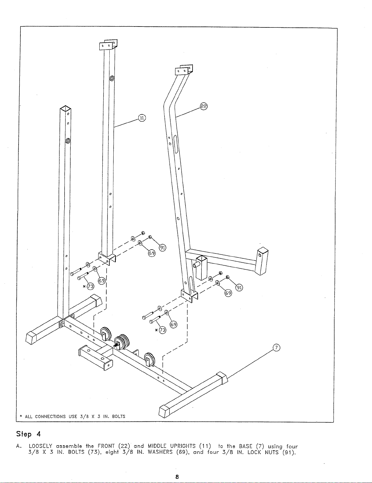
* ALL CONNECTIONS USE 5/8 × 5 IN. BOLTS
Sfep 4
LOOSELY assemble fhe FRONT (22)and MIDDLE UPRIGHTS (11) fo fhe BASE (7) using
5/8 X 5 IN. BOLTS (75), eight 5/8 IN. WASHERS (69), c~nd four 5/8 IN. LOCK NUTS (91).
3/8 X 3",
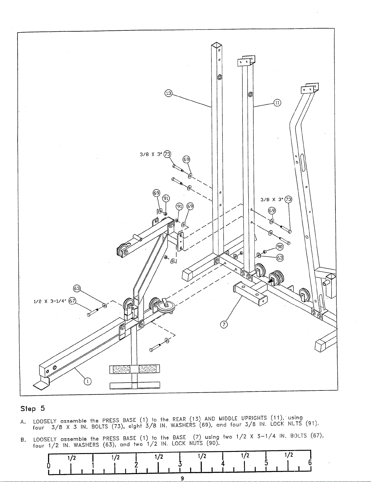
Step 5
A. LOOSELY assemble fhe PRESS BASE (1) to the REAR (15) AND MIDDLE UPRIOHTS (11),using
four 5/8 X 5 IN. BOLTS (75), eight 5/B IN. WASHERS (69), and four 5/8 IN. LOCK NLTS (91).
LOOSELY assemble fhe PRESS BASE (1) to the BASE (7) using two 1/2 X 5-1/4 IN. BOLTS (67),
B.
four 1/2 IN. WASHERS (65), ~nd two 1/2 IN. LOCK NUTS (90).
3
9
4
5
6
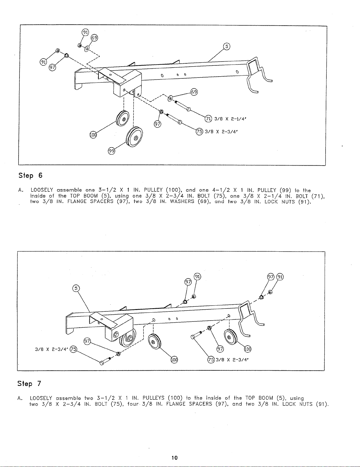
Step 6
LOOSELY assemble one 3-1/2 X 1 IN. PULLEY (100), and one 4-1/2 X 1 IN. PULLEY (99) to
inside of fhe TOP BOOM (5), using one 5/8 X 2-3/4 IN. BOLT (75), one 3/8 X 2-1/4 IN. BOLT (71),
fwo ,5/8 IN. FLANGE SPACERS (97), fwo 3/8 IN. WASHERS (69), and fwo 3/8 IN. LOCK NUTS (91).
3/8 X 2-314"
Step 7
LOOSELY assemble two 3-1,/2 X 1 IN. PULLEYS (100) to the inside of the TOP BOOM (5), using
two 3/8 X 2-3/4 IN. BOLT (75), four. 3/8 IN. FLANGE SPACERS (97), and two 3/8 IN. LOCK NUTS (91).
10
Loading...
+ 21 hidden pages
You need points to download manuals.
1 point = 1 manual.
You can buy points or you can get point for every manual you upload.


 Loading...