

Page 1
100101 LEG PRESS
ASSEMBLY INSTRUCTIONS
CLASS H
PART# 7037301
REV . B
WARNING:
Read and follow all directions
for each step to insure proper
assembly of this product.
1
Version: 100101
Revision: 06/21/01
Page 2
IMPORTANT NOTES
Please note:
* Thank you for purchasing the Parabody 100101 LEG PRESS. Please read these instructions
thoroughly and keep them for future reference. This product must be assembled on a flat,
level surface to assure its proper function.
We recommend cleaning your product (pads and frame) on a regular basis, using warm soapy
water. Touch-up paint can be purchased from your Parabody customer service representative
at (800) 328-9714.
There is a risk assumed by individuals who use this type of equipment. To minimize risk, please
follow these rules:
1. Inspect equipment daily . T ighten all loose connections and replace worn parts immediately.
Failure to do so may result in serious injury.
2. Do not allow minors or children to play on or around this equipment.
3. Exercise with care to avoid injury .
4. If unsure of proper use of equipment, call your local Parabody distributor or call the
Parabody customer service department at (800) 328-9714.
5. Consult a physician before beginning any exercise program.
T ools Required for Assembly
* 3/4” wrench
* 9/16” wrench
* Ratchet with 3/4” and 9/16” sockets
* Adjustable wrench
* 5/32” Allen wrench
* Tape measure
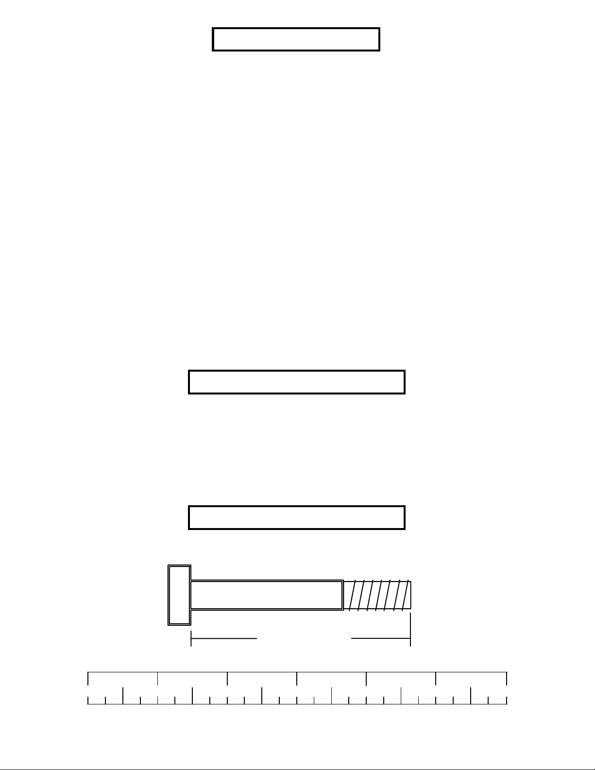
Bolt Length Ruler
NOTE: BOL T LENGTH IS MEASURED FROM THE UNDERSIDE OF THE HEAD OF THE BOLT.
BOL T LENGTH RULER:
1/2 1/2 1/2 1/2 1/2 1/2
0
1
BOLT LENGTH
2
345
2
6
Page 3

PARTS LIST
KEY
1
2
3
4
5
6
7
8
9
10
11
12
13
14
15
16
17
PART #
6574508
6573608
6655708
6575408
6573908
6476408
6575102
6597421
6574001
3103102
3116201
6177001
6405201
6416601
6467001
6500601
3102501
DESCRIPTION
BASE FRAME
SEA T FRAME
REAR TUBE
FOOT PLA TE
LEVER TUBE
HANDLE
ADJUSTMENT TUBE
SEA T P AD
3/4 X 8-1/4” SHAFT
1 X 8” GRIP
3-1/2” PULLEY
2-1/2 X 5-1/2” NON-SKID STRIP
2” SQ. END CAP
P ARAGLIDE (QTY. 8)
2” SQ. COVER CAP
2” WHEEL
3/8” FLA T W ASHER
QTY
1
1
1
1
2
1
1
2
2
2
1
8
14
1
2
2
8
KEY
18
19
20
21
22
23
24
25
26
27
28
29
30
31
32
33
PART #
3102601
3102802
3102807
3102801
3102804
3102941
3102922
3102904
3102935
3102918
3202107
6122703
6020601
3104901
3106803
6412001
DESCRIPTION
3/8” LOCK WASHER
3/8” LOCK NUT
3/8” LOW HEIGHT LOCK NUT
1/2” LOCK NUT
1/2” LOW HEIGHT LOCK NUT
3/8 X 1-1/2” BOLT
3/8 X 2-3/4” BOLT
3/8 X 3” BOLT
3/8 X 4-1/2” BOLT
1/2 X 3-1/4” BOLT
1/2 X 6-1/2” BOLT
3/8 ID X 3/8” SPACER
1/2” FLANGE BEARING
3/4” FLANGE BEARING
5/16” SET SCREW
3/8” SPRING PIN
QTY
4
2
1
2
2
2
2
2
1
2
2
2
8
4
4
1
3
Page 4
13
1
19
3
17
3/8 X 3” 25
15
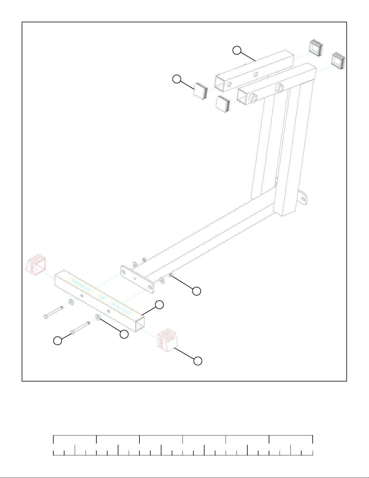
FIGURE 1
STEP 1:
• Attach two 2” SQ. COVER CAPS (15) onto the ends of the REAR TUBE (3) as shown in FIGURE 1.
• Insert four 2” SQ. ENDCAPS (13) into the ends of the BASE FRAME (1) as shown in FIGURE 1.
• SECURELY assemble the REAR TUBE (3) to the BASE FRAME (1) using two 3/8 X 3” BOLTS (25), four 3/8” FLAT WASHERS
(17), and two 3/8” LOCK NUTS (19). See FIGURE 1.
1/2 1/2 1/2 1/2 1/2 1/2
0
1
2
345
4
6
Page 5
14
2
13
33
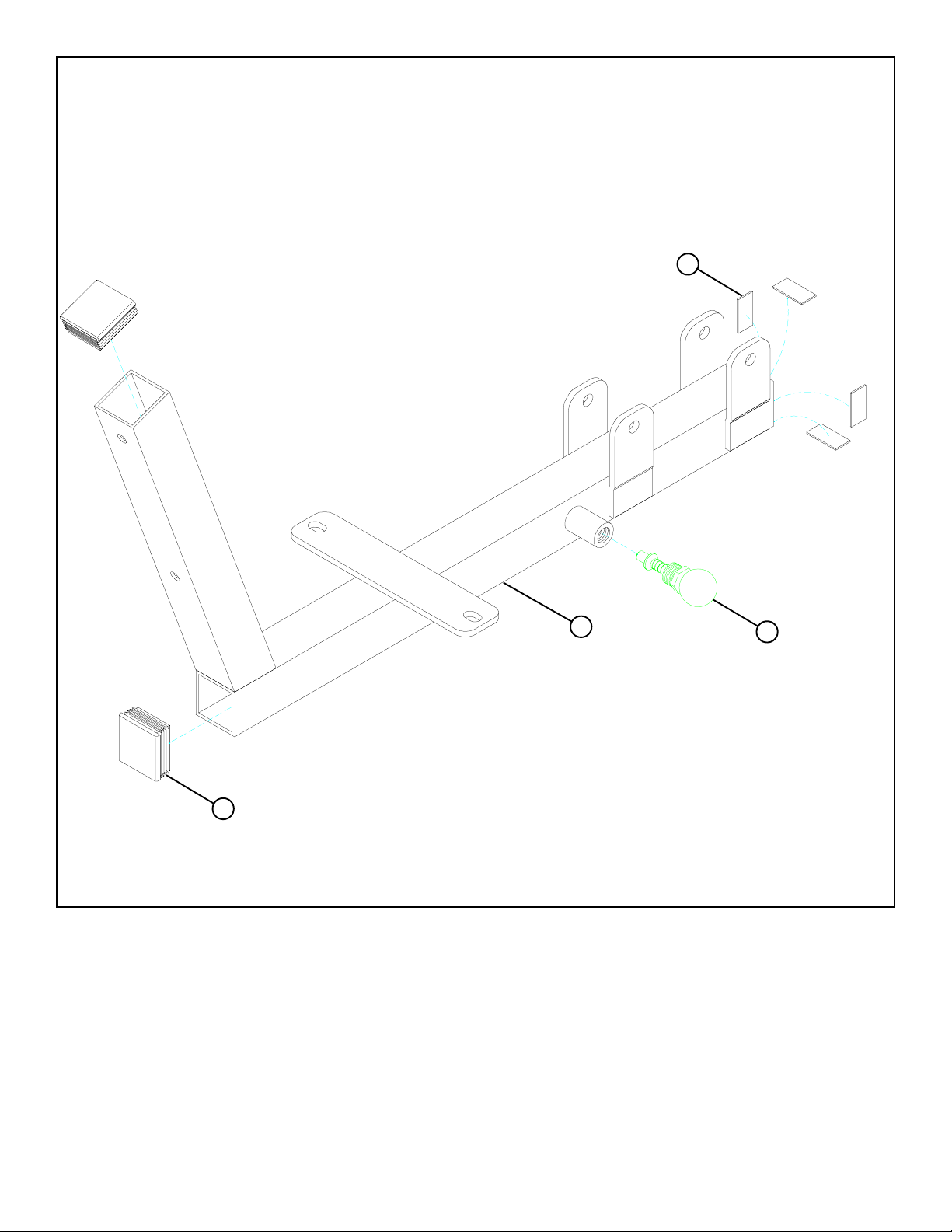
FIGURE 2
STEP 2:
• Insert two 2” SQ. ENDCAPS (13) into the ends of the SEAT FRAME (2) as shown in FIGURE 2.
• SECURELY assemble one 3/8” SPRING PIN (33) to the spring pin barrel on the SEAT FRAME (2) as shown in FIGURE 2.
• Attach four PARAGLIDE STRIPS (14) to the inside of the SEAT FRAME (2) using the following steps:
• Thoroughly clean all surfaces where the PARAGLIDE STRIPS (14) are to be attached.
• Remove the PARAGLIDE STRIPS (14) from the paper backing and firmly apply them to all shown surfaces.
5
Page 6

3/8” LOW HEIGHT 20
7
11
29
17
16
3/8 X 4-1/2” 26
14
FIGURE 3
STEP 3:
• SECURELY assemble one 3-1/2” PULLEY (11), two 2” WHEELS (16), two 3/8” FLAT WASHERS (17), and two 3/8 ID X 3/8”
SPACERS (29) to the ADJUSTMENT TUBE (7) using one 3/8 X 4-1/2” BOLT (26) and one 3/8” LOW HEIGHT LOCK NUT (20)
as shown in FIGURE 3.
• Attach four PARAGLIDE STRIPS (14) to the outside of the ADJUSTMENT TUBE (7) using the following steps:
• Thoroughly clean all surfaces where the PARAGLIDE STRIPS (14) are to be attached.
• Remove the PARAGLIDE STRIPS (14) from the paper backing and firmly apply them to all shown surfaces.
1/2 1/2 1/2 1/2 1/2 1/2
0
1
2
345
6
6
Page 7

7
SPRING PIN
2
FIGURE 4
STEP 4:
• CAREFULLEY slide the ADJUSTMENT TUBE (7) over into the SEAT FRAME (2) and engage the SPRING PIN into one of
the adjustment holes. See FIGURE 4.
STEP 5:
FIGURE 5
5
31
• Insert two 3/4” FLANGE BEARINGS into
each of the two LEVER TUBES (5) as
shown in FIGURE 5.
31
5
7
Page 8

5/16” SET SCREW 32
5
17
9
1
FIGURE 6
STEP 6:
• Insert four 2” SQ. END CAPS (13) into the ends of two LEVER TUBES (5) as shown in FIGURE 6.
• SECURELY assemble the LEVER TUBES (5) to the BASE FRAME (1) using two 3/4” SHAFTS (9) and SECURE in place
using four 5/16” SET SCREWS (32). See FIGURE 6.
1/2 1/2 1/2 1/2 1/2 1/2
0
1
2
345
8
6
Page 9

13
4
30
5
1
FIGURE 7
STEP 7:
• Insert four 2” SQ. END CAPS (13) into the ends of FOOT PLATE (4) as shown in FIGURE 7.
• Insert eight 1/2” FLANGE BEARING (30) into the LEVER TUBES (5) as shown in FIGURE 7.
9
Page 10

1/2” LOW HEIGHT 22
12
4
5
28 1/2 X 6-1/2”
FIGURE 8
STEP 8:
• SECURELY assemble the FOOT PLATE (4) to the LEVER TUBES (5) using two 1/2 X 6-1/2” BOLTS (28) and two 1/2” LOW
HEIGHT LOCK NUTS (22) as shown in FIGURE 8.
• CAREFULLY attach eight NON-SKID STRIPS (12) to the FOOT PLATE (4) as shown in FIGURE 8.
1/2 1/2 1/2 1/2 1/2 1/2
0
1
2
345
10
6
Page 11

21
5
2
27 1/2 X 3-1/4”
FIGURE 9
STEP 9:
• SECURELY assemble the SEAT FRAME (2) to the LEVER TUBES (5) using two 1/2 X 3-1/4” BOLTS (27) and two 1/2” LOCK
NUTS (21) as shown in FIGURE 9.
11
Page 12

2
8
6
17
18
3/8 X 1-1/2” 23
FIGURE 10
STEP 10:
• SECURELY assemble the SEAT PAD (8) to the HANDLE (6) and the SEAT FRAME (2) using two 3/8 X 1-1/2” BOLTS (23),
two 3/8” LOCK WASHERS (18), and two 3/8” FLAT WASHERS (17). See FIGURE 10.
1/2 1/2 1/2 1/2 1/2 1/2
0
1
2
345
6
12
Page 13

2
18
24 3/8 X 2-3/4”
10
8
FIGURE 11
STEP 11:
• SECURELY assemble the SEAT PAD (8) to the SEAT FRAME (2) using two 3/8 X 2-3/4” BOLTS (24) and two 3/8” LOCK
WASHERS (18) as shown in FIGURE 11.
• Slide two 1 X 8” GRIPS (10) over each HANDLE (6) as shown in FIGURE 11.
13
Page 14

FIGURE 12
STEP 12:
• To adjust the SEAT, sit in the LEG PRESS, gently press against the FOOT PLATE and pull back on the SPRING PIN.
• Refer to the LEG PRESS ADAPTOR assembly instructions to attach the 832102 LEG PRESS to the home gym.
Thank you for purchasing the Parabody 100101 LEG PRESS. If unsure of proper use of equipment, call
your local Parabody distributor or call the Parabody customer service department at (800) 328-9714.
1/2 1/2 1/2 1/2 1/2 1/2
0
1
2
345
14
6
 Loading...