

Page 1

DIGITALCINEMATOGRAPHY
CAMERA SYSTEM
HD900FOPERATIONMANUAL
ULTRAPRECISION EQUIPMENTFORTHEMOTIONPICTUREINDUSTRY
Page 2
writtenby
EricErb
Andrew Young
design,photos,andlayout
EricErb
Andrew Young
2
photographswereshotusingtheKodakPreview System withPrimolenses
HD900FOPERATIONMANUAL
COPYRIGHT2002
VERSION2.1.2
4/2002
Page 3

INTRODUCTION
In 1997,Panavision and Sony announced their
collaboration on the developmentofa24P digitalhigh
definition camerasuitable foruse by filmmakers to
create big screen motion picture image quality. We
knew,from 45 years ofexperience,thata complete
imaging system approach was the only way for
traditionalfilm crewstomakeaseamlesstransitioninto
digitalproduction.Withthisinmind,wemadeanumber
ofmodificationstotheSonyHDW-F90024Pcamera.For
starters,the Panavised camera received aheavy duty
frontplate and lensmountmodified to work with our
speciallydesignedPrimoDigitalTMlenses.Thesystem now
accommodates mostofourstandard film camera
accessories as wellas new accessories designed
exclusivelyfordigitalcinematography.
In addition to the mechanicalmodificationsto the
camera,auniqueopticalpre-filtergivesyoubettercolor
matching with film emulsionsand enhanced resolution
forblue screen effectscinematography. Last,butnot
least,wedesigned the new ULTRAVIEWviewfinderfor
studio and handheld cine-style use. Itpresentsa 2
timeslargerimagealongwithagreaterdiopterrange.
HD900F
INTRODUCTION
Panavision iscommitted to continuouslydeveloping our
DigitalImaging system in close collaboration with our
clients,justaswehavedonewithourfilm systemsover
thelast45years.Now yourHD projectwillbenefitfrom
the same dedication to customerservice and superior
imagequalitythatisthehallmarkofPanavision.
3
Page 4

TABLEOFCONTENTS
SECTION 1.0 GENERALSPECIFICATIONS
1.1 CAMERASPECIFICATIONS
1.2 CONNECTORSPECIFICATIONS
1.3 FRAMERATESAND SHUTTERSPEEDS
1.4 CAMERAWEIGHTS
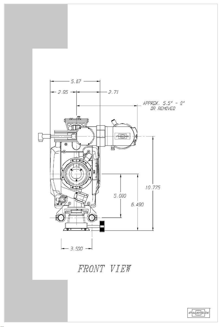
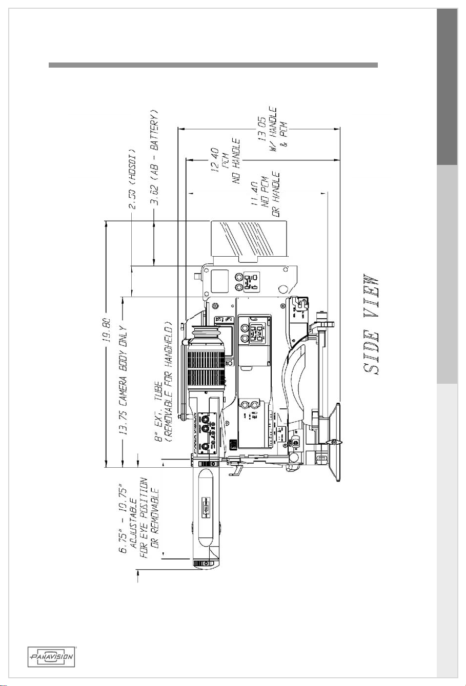
1.5 CAMERAMEASUREMENTS
1.6 SIDECAMERAVIEWS
1.7 FRONTANDREARCAMERAVIEWS
1.8 PROGRESSIVEVS.INTERLACE
1.9 GENERALIMAGINGCONSIDERATIONS
SECTION 2.0 PACKING AND SHIPPING
2.1 CAMERABODYCASE
2.2 ACCESSORYCASE
SECTION 3.0 PRIMO DIGITAL™ LENSES
3.1 PRIMO DIGITAL™ LENSDESIGN
3.2 FILM /HDCOMPARATIVERESOLUTION
3.3 ASPHERICALAND FISHEYEATTACHMENTS
3.4 PRIMO DIGITAL™ LENSEXTENDERS
3.5 SETTING BACKFOCUS
4
4
SECTION 4.0 CAMERAASSEMBLY
4.1 FRONTFACEPLATEANDFOLLOW FOCUS
4.2 VIEWFINDER
4.3 ON-BOARDMONITORAND BRACKET
4.4 LENSLIGHT
4.5 VOLTAGEUPCONVERTER
4.6 CARRYHANDLE
4.7 SIDEPANELCONNECTORS
4.8 MIRANDADOWNCONVERTER
4.9 REARPANELCONNECTORS
4.10 HDSDIADAPTER
4.11 ON-BOARDBATTERY
Page 5

TABLEOFCONTENTS
SECTION 5.0 CAMERAOPERATION
5.1 HDCAM CASSETTE
5.2 VTRCONTROLS
5.3 VIEWFINDERCONTROLS
5.4 REMOTECONTROL
5.5 FILTERWHEELS
5.6 MEMORYSTICK
5.7 TIMECODE
5.7.1 TIMECODESWITCHESAND BUTTONS
5.7.2 USING TIMECODE
5.8 MAIN CAMERASWITCHES
5.9 MENUS
5.9.1 OPERATIONMENU
5.9.2 PAINTMENU
5.9.3 SETTINGTHEFRAMERATE
5.10 VIEWFINDERFRAMELINEMARKINGS
5.10.1 TV16X9TRANS&4X3TRANS/SAFE
5.10.2 TV16X9TRANS&1.85THEATRICAL
5.10.3 TV16X9TRANS&2.40THEATRICAL
5.11 PREPROUTINE
5.12 A.C.PRE-ROLLCHECKLIST
5.13 PRODUCTION CONSIDERATIONS
5.14 TROUBLESHOOTING
5.15 SMARTLENS
5.16 METADATA
HD900F
TABLEOFCONTENTS
SECTION 6.0 MONITORS
6.1 MONITORS
6.2 9"HDSDIMONITOR
6.3 14"HDSDIMONITOR
6.4 24"HDSDIMONITOR
6.4.1 24"MONITORCALIBRATION
6.4.2 24"MONITORFRAMELINESETTINGS
6.5 HD SDIWAVEFORM MONITOR
SECTION 7.0 INDEX
5
Page 6

6
Page 7
1.0 GENERALSPECIFICATIONS
HD900F
GENERALSPECIFICATIONS
1.0
7
Page 8

1.1 CAMERASPECIFICATIONS
Imager RGB 2/3"CCDs
EffectivePixels 1920(H)x1080(V)each
2.1millionpixelseach,foratotalof6.3
.378"x.212"
Power 12vDC (range11-17v)
Built-inFilters
NDFilters CCFilters
1: Clear B: 3200K
2: .6-(2Stops) C: 4300K
3: 1.2-(4Stops) D: 6300K
4: 1.8-(6Stops)
LensMount PanavisionHD Mount(proprietary)
Baseplate PanavisionDovetailwith5/8"rods
Steadicam®Plates Bottom DovetailPlateforRegularMode
TopHandlePlateforLow Mode
Sensitivity Minimum ISO 320tungsten
CassetteTape HDCAM:BCT-22HD,BCT-32HD,orBCT-40HD
RunningTimes 22min.@ 30fps or 27.5min.@ 24fps
32min.@ 30fps or 40.0min@ 24fps
40min.@ 30fps or 50.0min.@ 24fps
AudioQuality 20bit,48kHzDigital(upto4channels)
PresetStorage SonyMemoryStick
Eyepiece PanavisionUltraview®-2modes:Extension
andIntermediate/Hand-held
SMARTLENS™ Highresolutiondigitalencoderstorecord
Compatibility T-stop,focus,andzoom positions
Recordableupto16channelsonto
Audiochannels3and4onHD SDIadapter
8
8
Page 9

1.2 CONNECTORSPECIFICATIONS
DCIn XLR,4pinmale 11-17v
Pin1–ground(-)
Pin4–positive(+)
DCout Hirose,12VDC,4pin (2Amax)
HD900F
REM Lemo,10pin1B
Pin1-VTRStart/Stop
Pin6-Ground
VTR,shutter,menucontrols(HDRP)
AudioIn 2Channels–XLR,3pinfemale
Pin1–Ground
2–Input(hi)
3–Input(low)
2additionalchannelswithHDSDIadapter
(HDCAA)
MicIn 1Channel–XLR,3pinfemale(+48v)
Pin1–Ground
2–Input(hi)
3–Input(low)
AudioOut 2Channelon1–XLR,5pinmale(E-E)
Pin1–AnalogGround
2–Ch.1Audio
3–Ch.1Ground
4–Ch.2Audio
5–Ch.2Ground
2additionalchannelswithHDSDIadapter
(HDCAA)
GENERALSPECIFICATIONS
1.1/2 GENERAL&CONNECTORSPECS
GenlockIn BNC
GenlockOut BNC(usinganalogYchannel)
TimecodeIn BNC
TimecodeOut BNC
VideoOut Y,Pb,PrAnalog
HDSDI(withHDCAadapter)
RemoteControl Hirose(special)–8pin
9
Page 10

1.3 FRAMERATESAND SHUTTERSPEEDS
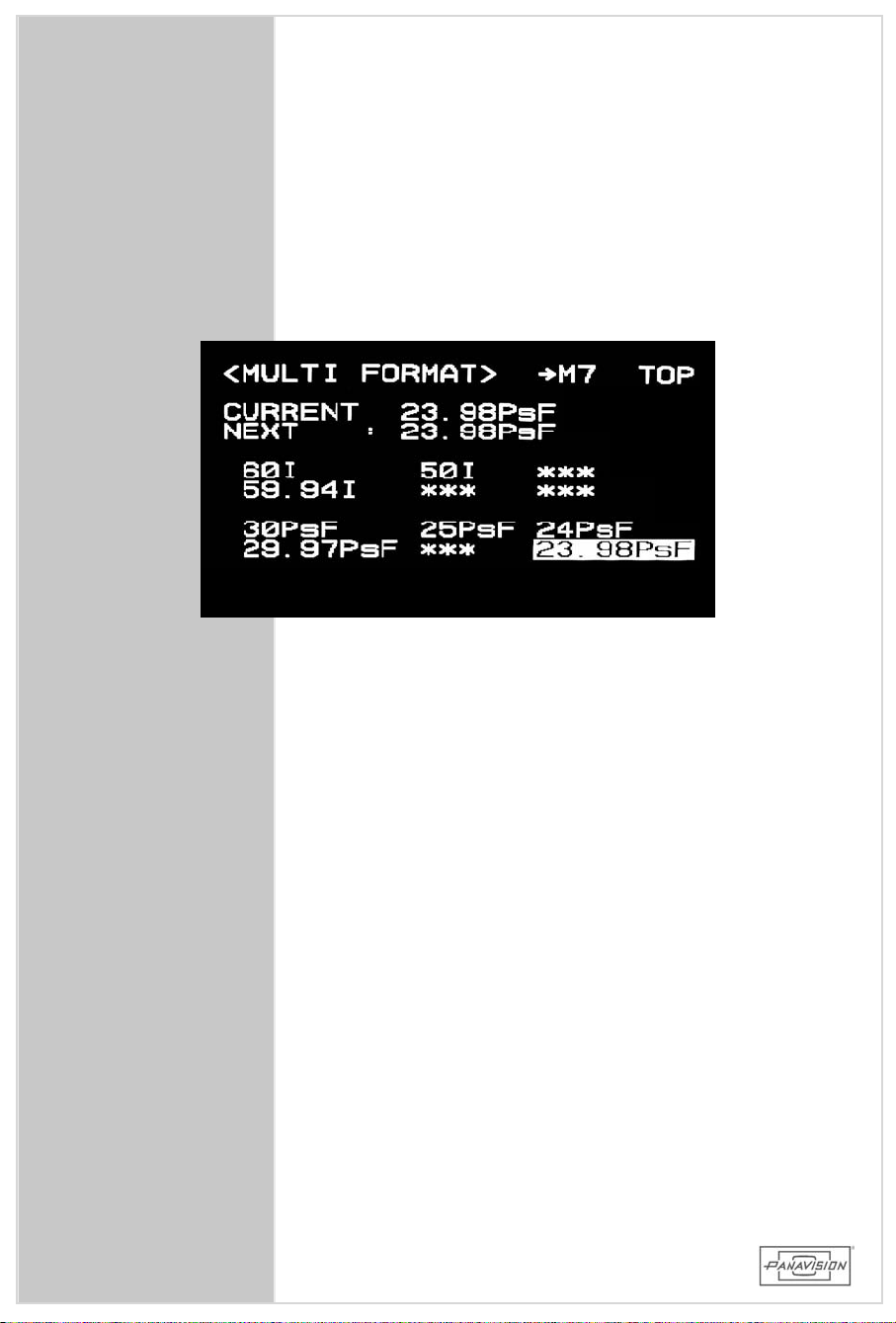
FrameRates(MAINTENANCEMENUpage:M7)
Progressive Interlace
23.98PsF 50i
24PsF 59.94i
25PsF 60i
29.97PsF
30PsF
ShutterAngles(PAINT MENU page:P12 orwith the Remote
Control)
SHUTTERSPEED EQUIV.SHUTTERANGLE
ShutterOFF= 1/24sec 360.00degree
1/32 270.00
1/48 180.00
1/96 90.00
1/125 69.12
1/250 34.56
1/500 17.28
1/1000 8.64
ECS- ExtendedClearScan 24Hz-2200Hz@ 24fps
Usedto setintermediate shutterspeedsand /orshoot
practicalmonitors.
Theequivalentshutterangle,forafilm camera,isfoundbythe
followingformula: 360*fps/Hz= shutterangle.
10
10
Page 11

1.4CAMERAWEIGHTS
Body(withoutSDI) HD900F 14.9lbs.
Body(WithSDI) HD900F,HDCA 17.2
SDIAdapter HDCA 2.3
ExtensionEyepiece HDET,HDEP 4.8
Intermediate/HHEyepiece HDEP 3.6
Follow Focusw/1Knob HDFB,HDFD,MFF 1.9
HandHeldRig HDHR 2.4
Clip-onMattebox MBPC 1.0
TopSteadicam®Plate HDLM 0.5
Bottom Steadicam
VoltageUpconverterw/cable HDUC 0.9
AntonBauerBattery AB100 5.4
LENSES
®
Plate HDSP 1.2
HD900F
GENERALSPECIFICATIONS
PrimoDigitalTM5mm PrimeLens SD5 3.0
PrimoDigitalTM7mm PrimeLens SD7 3.2
PrimoDigitalTM10mm PrimeLens SD10 3.7
PrimoDigitalTM14mm PrimeLens SD14 2.8
PrimoDigital™ 20mm PrimeLens SD20 3.6
PrimoDigital™ 35mm PrimeLens SD35 2.9
PrimoDigitalTM6-27mm w/Motor SDZW 8.0
PrimoDigitalTM25-112mm w/Motor SDZT 7.0
PrimoDigitalTM9.5-105mm w/Motor SLZ11D 23.0
PrimoDigitalTM8-72mm w/Motor SDZ9 8.6
1.4XExtenderforPrimoDigital™ Zoom 1.4XSD 0.7
2XExtenderforPrimoDigital™ Zoom 2XSD 0.9
DoubleAsphereAttachmentfor5mm CDA 1.2
WideAngleFisheyeAdapterfor7mm WFA 1.4
HandHeldConfiguration: 29.3
(HandHeldViewfinder,SDI,HDUC,Follow
Focusw/1Knob,HDHR,MBPC,Remote–
NoLens)
1.3/4FRAMERATES&CAMERAWEIGHTS
11
Page 12
12
Page 13
1.5 CAMERAMEASUREMENTS
HD900F
GENERALSPECIFICATIONS
13
1.5 CAMERAMEASUREMENTS
Page 14
14
Page 15
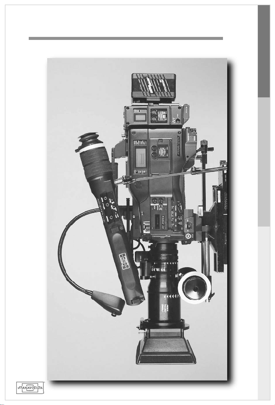
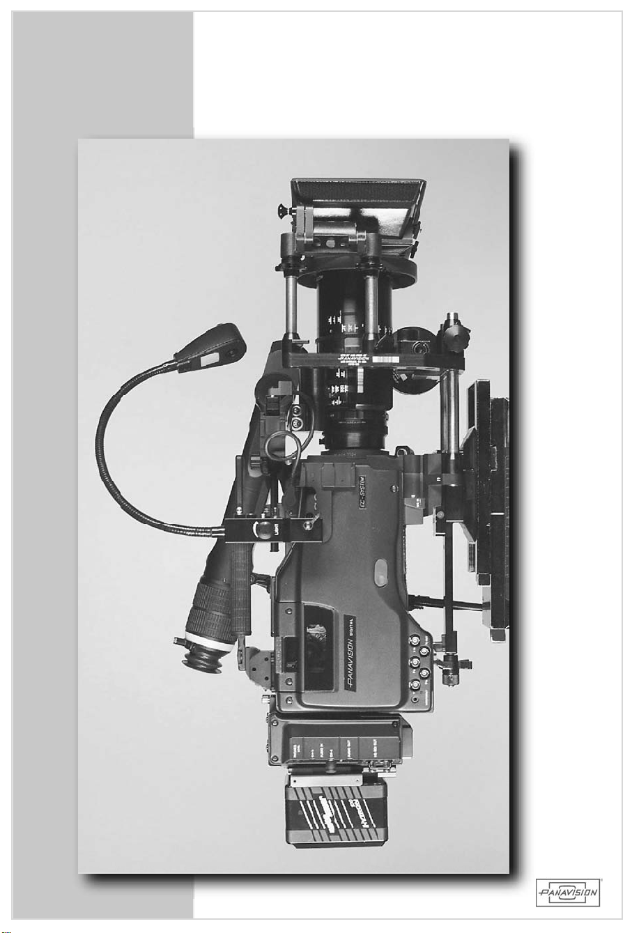
1.6 SIDECAMERAVIEWS
HD900F
GENERALSPECIFICATIONS
15
1.6 SIDECAMERAVIEWS
Page 16
16
Page 17
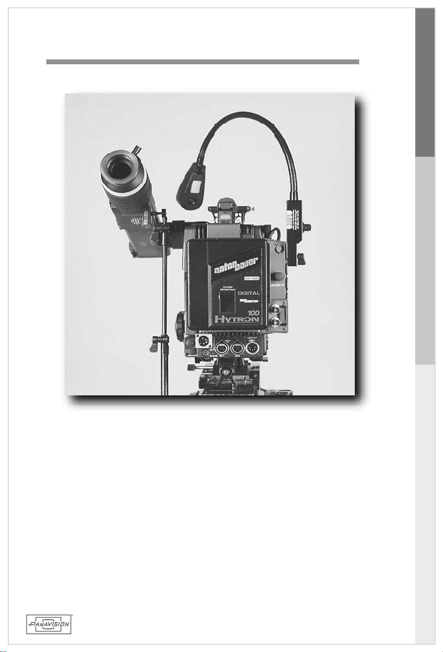
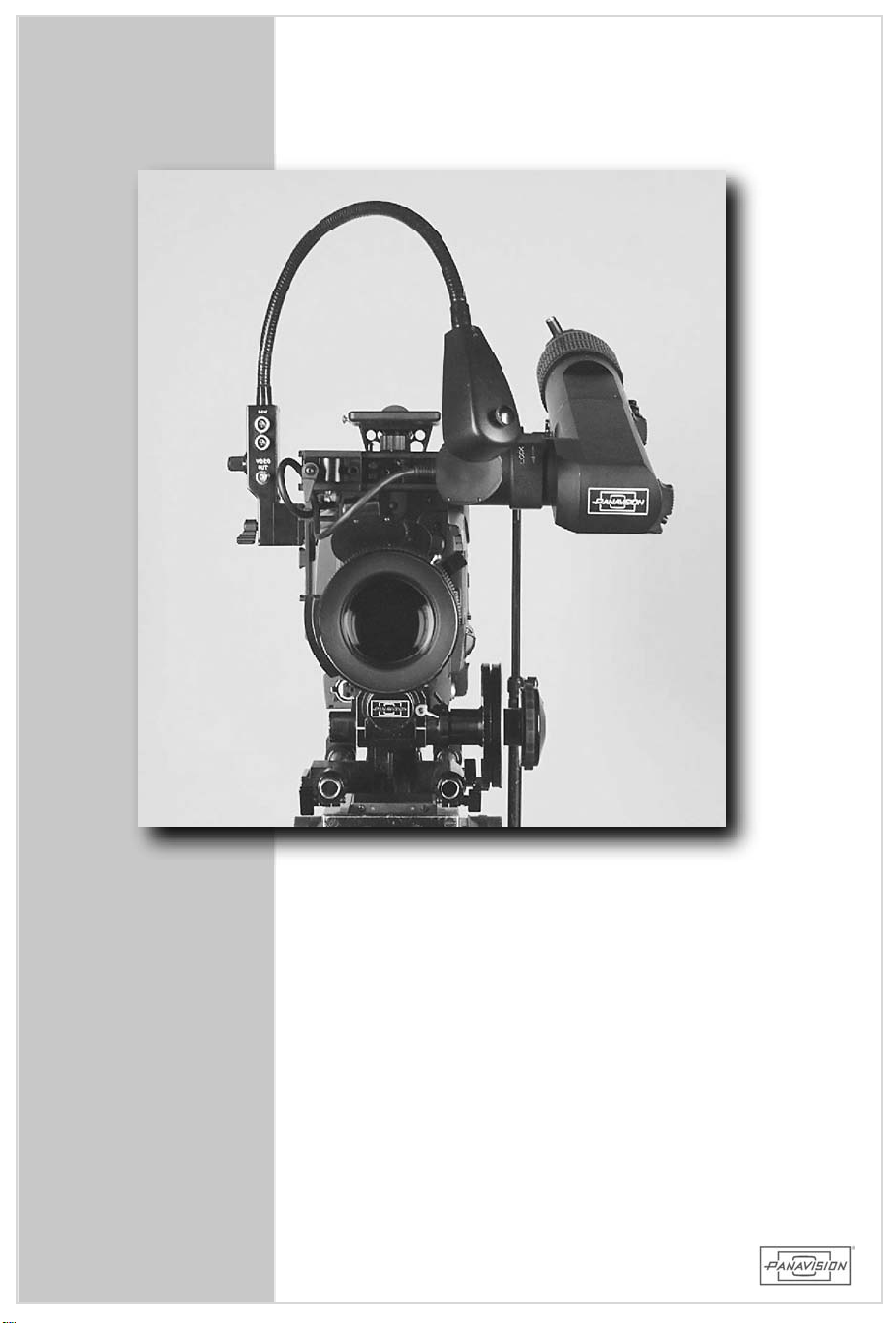
1.7 FRONTAND REARCAMERAVIEWS
HD900F
GENERALSPECIFICATIONS
17
1.7FRONTAND REARCAMERAVIEWS
Page 18
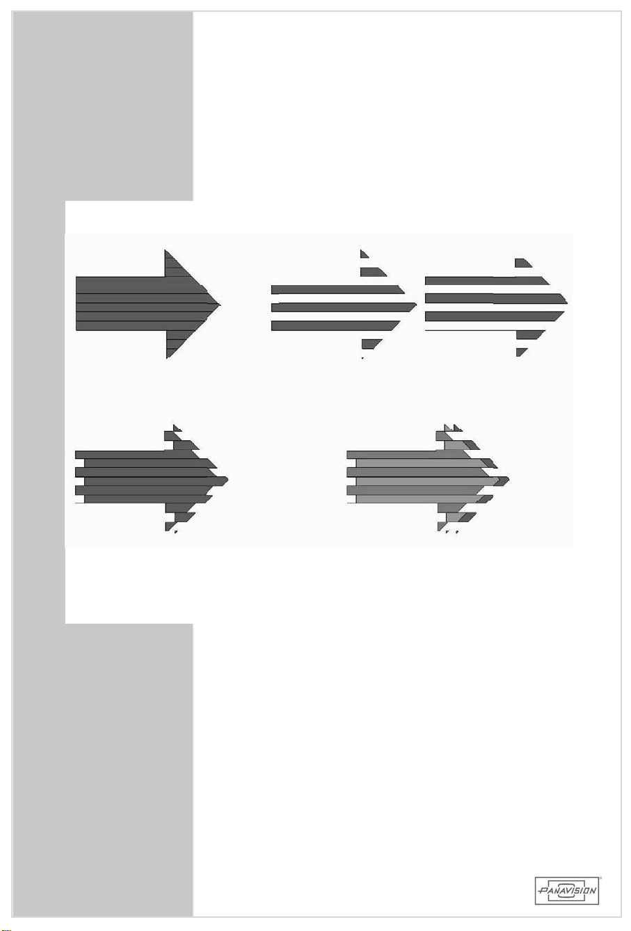
StaticInterlaced
Imageconsistsoftwo
fields
Field1(oddlines
1,3,5,etc.)
Field2(evenlines
2,4,6,etc.)
Movingimageappearsto
theeyeasablurred,brokenedge
18
60 field to 24 frame
conversionrequiresthe
m ixing of 3 fields
resulting in additional
motionblur
Page 19

1.8 PROGRESSIVEVS.INTERLACE
The24PHD ElectronicCinematographyCameraSystem
is a PROGRESSIVE capture deviceunlike oldervideo
cameras thatcapture the image in an INTERLACE
manner.
INTERLACE: A videoscanningsystem wheretheodd
numbered linesare scanned separately
from theevennumberedlines.Theodd
numberedlinesform fieldone,theeven
lines make up the second field. The
combinationoftwofieldscomprisesone
frame.
PROGRESSIVE: A video system in which alllines
comprising aframe are scanned in
sequenceratherthaninterlaced.
HD900F
GENERALSPECIFICATIONS
The interlace mode ofcapture hasinherentmotion
artifactsand is difficultto transferto film. The
progressive mode ofshooting capturesthe complete
resolution atonce,atthe same pointin time;and
thereforeallowsaperfectone-to-onetransfertofilm.
1.8 PROGRESSIVEVS.INTERLACE
19
Page 20

1.9 GENERALIMAGING CONSIDERATIONS
TheHD900Fhasawiderangeofmenusettingsthatallow theusertocontrolthe
lookofthepicture.Thesesettingscanbeapowerfultooltochangeormodifythe
captured image.Mostcomponentsofthe video signalcan be manipulated.
Levels,saturation,gammaand matrixwillhaveamajorinfluenceoverthefinal
videooutput,beitforTVorfilm.
Whilethereisnorightorwrongwayto approachhow thecameraisused,you
shouldbe awareofthe consequencesofemployingcertainmenufunctions.We
do notdeterminewho willmake adjustmentsorwhen these functionswillbe
employed,butinmostcases,theyaremadeatthebehestoftheDP.Whilethese
featuresmayprove usefulforshowsthatarevideo outonly(TV),ifmisused,
theycanhaveirreversibleconsequencesonafilm-outshow (feature).Judicious
use ofthese featurescan prove beneficial.However,minimum manipulation of
theimagethatwillresultin a cleancameramasterisdesirable.Itisbetterto
leavethe decisiontoalterthe imageforthelessstressfulenvironmentofthe
postproductionsuite. Postproductiontoolsofferthe ability tomanipulatethe
imagetoamuchhigherdegreethanthecameraallows.Thefollowinglistisnot
inclusiveofeverymenufunction,butprovidesabriefexplanationofwhycertain
precautionsshouldbeheeded.
Detail:Thedetailfunction willprovideartificialenhancementtothevideoimage
particularly around the edge ofan object.Thisfeature,like severalothers,is
incorporated into the camera forlive TV broadcastproductions. Historically,
detailcircuitswere used to compensate forlimitationsofopticsorelectronics.
While this isusefulforTV applications,employing detailforafilm output
productionwillputunnaturaledgingaroundthesubject.Inaddition,useofdetail
willmakethequalityofCGIormattesverypoorsincethematteprocesstriesto
avoidanyappearanceofedges.
DCC:DCCisDynamicContrastControlorautoknee.Itisaccessible througha
toggle switch on the camera body.Itisusedduring newsordocumentary
situationswhere thereis little ornocontroloflighting andcontrastratios.If
thereisa brightobjectin the scenethatisover100% whitelevel,DCC will
automaticallypulltheleveldown(compress)sothehighlightwillnot"blow out".
Forascriptedproject,itcanbeseenthatautomaticcorrectionofhighlightscould
addundesirableelementstothesceneasthecameramovesorpansthroughout
the scene.While controlofthehighlights isnecessary,itisbestto use the
manualkneeandslopefunctionstoachievethedesiredresult.
BlackGamma:Thiscircuitallowsforstretchorcompression ofthe toe (black)
portion ofthevideo signal.Thiscan be usedtoaffectthecontrastin the dark
areasofthepicturewhile notchangingthemid-tonesorhighlights.Since this
portionofthesignalcontainsthehighestamountofgain,itisclosesttothenoise
floor.Consequently,expandingthesignalwillalsointroducemorenoiseintothe
picture.Thismaynotalwaysbeadesiredadditiontothefinallook.Forafilm-out
project,testingisprudent.
20
20
Page 21

1.9 GENERALIMAGING CONSIDERATIONS
Matrix:Thematrixisaseriesofmathematicalcalculationsthatareappliedto
thecoloroutputofthecamera.Itspurposeistomatchthecolorspaceofthe
cameratothefinaldisplaydevice.Itissimilartocertainequalizationcurves
thatareemployedin therecordingindustry to ensure thattheplayback
system willreproduce the originalrecordingfaithfully.In the video world,
matrixisused toprovideasetof equationsthatrelateto thereproducing
characteristicsofvarioussetsofphosphorsthatareusedinTVpicturetubes.
Thisfunction(likeothersonthecamera)hasrootsintheearlydaysofcolor
television when technology and economicsdetermined thatsome circuits
would be placed in thecameraandothersin the receiver.Aswith detail,
matrixcanproveusefulforabroadcastorvideoonlyproduction.Useofthe
matrixforafilm-outproductioniscautionedsincethefilm-outdevicewillnot
beabletorecreatethepropercolorspacefrom thecameratomatchthefilm
emulsion(theequationisnolongervalid).Ifcolormanipulationisdesired,it
isrecommended thatone shootatestusing thematrix to createthe
appropriatelook.Thistestcanbeusedasaguideforthefacilitythatwillbe
doingthefilm-out.
Useofthecamerainthe presetmodeswillproduce perfectly good images
thatcan bemanipulated witha much higherdegree ofcontrolin the post
environment. Inshort,youdonotneedtohaveacomprehensiveknowledge
ofthe paintmenu to producea good image. Again,there isnorightor
wrongway,butthismanualaddressesthosefeaturesthatarenecessaryfor
acameraassistanttomaster.
HD900F
GENERALSPECIFICATIONS
Duetoinherentdifferencesin imagingcharacteristicsbetweena CCD,a
monitor,and the human eye,certain translationsare necessary. The
Gamma andMatrix settingsinterpretthe CCD imageso thatthemonitor
imagewillapproximatetheactualsubject.
Gamma should alwaysbe turned ON and setto COARSE 0.45,TABLE
STANDARD 5. Thisreferences the ITU REC 709 standard.Thisgamma
correction isespeciallyimportantforvideo output,andcan be manipulated
forfilm output,andsoshouldbeleftonallthetime.(seesec5.9.2)
1.9 GENERALIMAGINGCONSIDERATIONS
21
Page 22

1.9 GENERALIMAGING CONSIDERATIONS
Shooting24PforFilm output:
Since the HD monitoris much closerto thefinalvideo image,butonly an
approximation ofthe film image,there are some recommendationsin orderto
maximizequalityoffinalfilm output:
-GAMMAON asabove
-MATRIXOFF
-GAINsetto6dBorless,toavoidaddingexcessivenoisetofinalimage.
-Uselessdiffusion.Considerusingafilterof1/2thevalueusedwithfilm negative.
-DETAILOFF Thisisespeciallyimportantbecauseitwilldegradethefilm output.
Wecautionagainstusingpaintmenusforimagemanipulation iffinishing on film
because the monitorimage and painteffectsdo notdirectlycorrelatetothe film
image,andtheyareusuallyirreversible.
Shooting24PforVideooutput:
(Nofuturefilm-outforeseenorplanned)
When shooting forvideo finish,the HD monitoris in effectyourfinalimage.
Therefore adjustmentscan be madein thecamera withmoreconfidence in the
intendedresults.Standardrecommendedsettingsare:
-GAMMAON asabove
-MATRIXON,PRESETON,ITU-709
-USERMATRIXOFF
-MULTI-MATRIXOFF
- GAINsetto6dBorless.
Allthepaintadjustmentscanbesetforcreativeeffect,buttheusermustbeaware
thatmany settingscannotbe undonein post. Ontheotherhand,ifthecamera
imageisrecordedclean,manypowerfulcreativemanipulationsareavailableinthe
colorcorrectionstage.
NOTE: TheMATRIX mustbeOFFforblueorgreen screenshotsbecauseitmay
NOTE: TorestorethepaintmenustotheirPanavisiondefaultsettings,recallthe
22
22
createundesirableartifacts.
STANDARDfileonmenupageP13,byclickingonittwice.
Page 23
2.0 PACKING ANDSHIPPING
HD900F
PACKING AND SHIPPING
2.0
23
Page 24
24
Page 25

2.1 CAMERABODYCASE
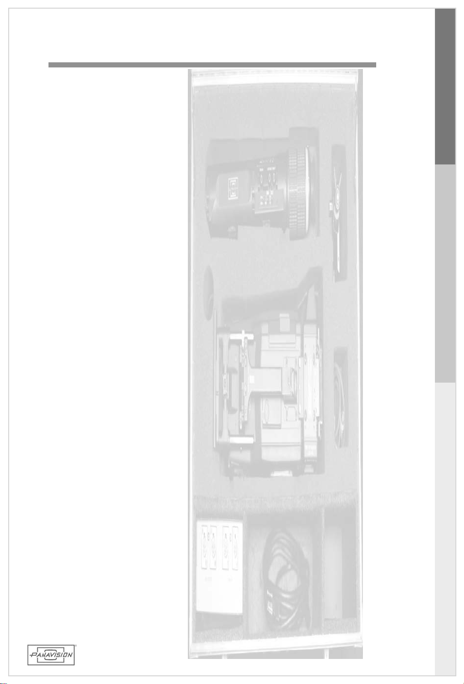
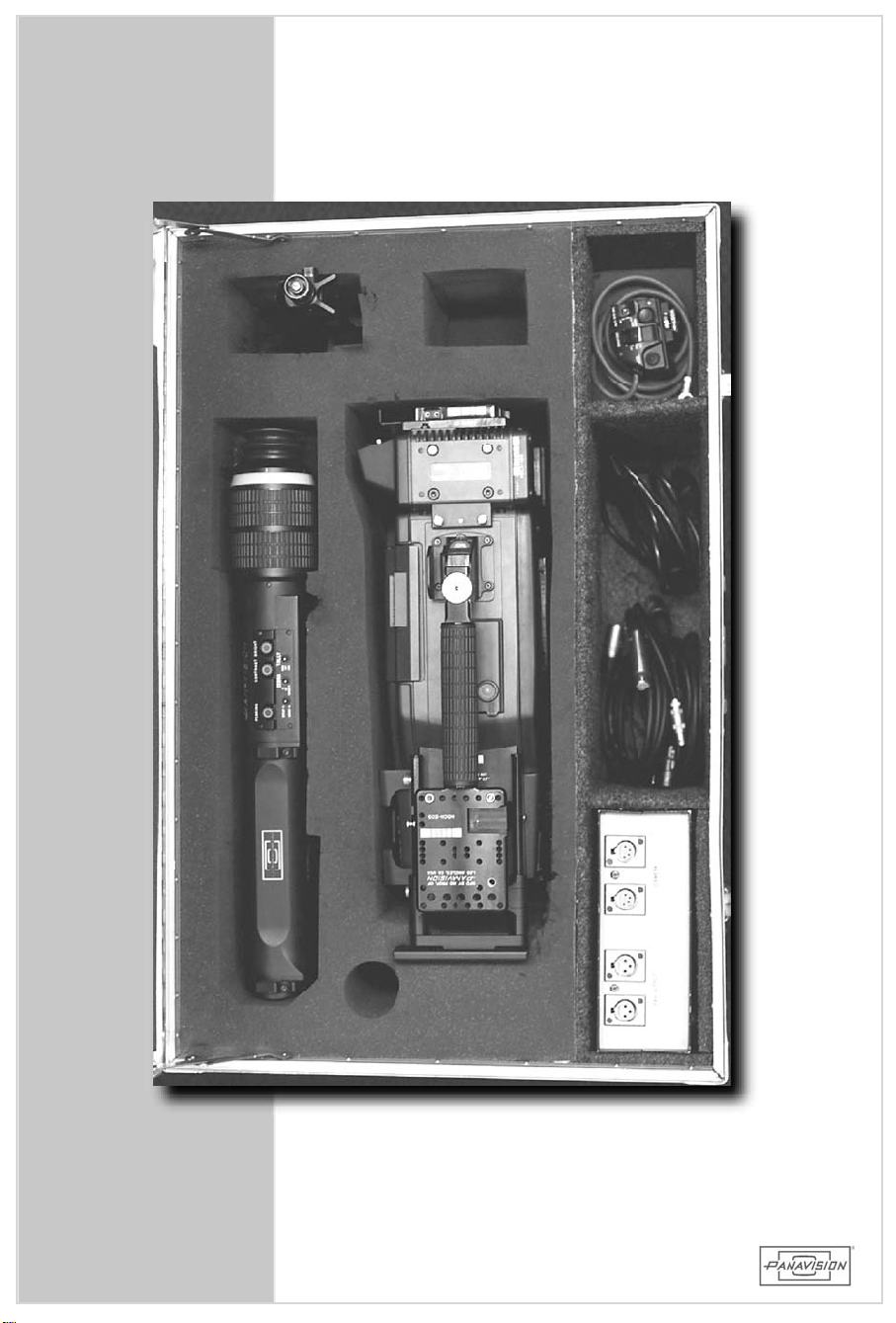
The HD900Fcamerasystem iscomprisedof2 cases,one
containing the camera bodyand the othercontaining the
camera accessories. The camera isstored withoutthe
eyepieceattached.
HD900F
Includedwiththecameraisan AC to DC powerconverter
(HDPS)with 224V DC and 2 12V DC outputsforcamera
andaccessorypower.
CASECONTENTS:
HD900F CameraHD900F
HDEP HD Ultraview Viewfinder
HDET HD ExtensionTube
HDVP HDViewfinderPivot
HDCAorHDCAA HDSDICam Adapter
(dataoraudio)
HDRP HDRemoteControlPanel
HDPCM HDCameraMount
ABSU orABGM ABSonyUpconverter
/GoldmountBatteryAdapter
HDPS HD 24/12DCPowerSupply
CBLE-IECNA IEC/N.AmericaMainsPlug
CBLE-12P(2) 12VPowerCable(XLR4)
PACKING AND SHIPPING
2.1 CAMERABODYCASE
25
Page 26
26
Page 27

2.2 ACCESSORYCASE
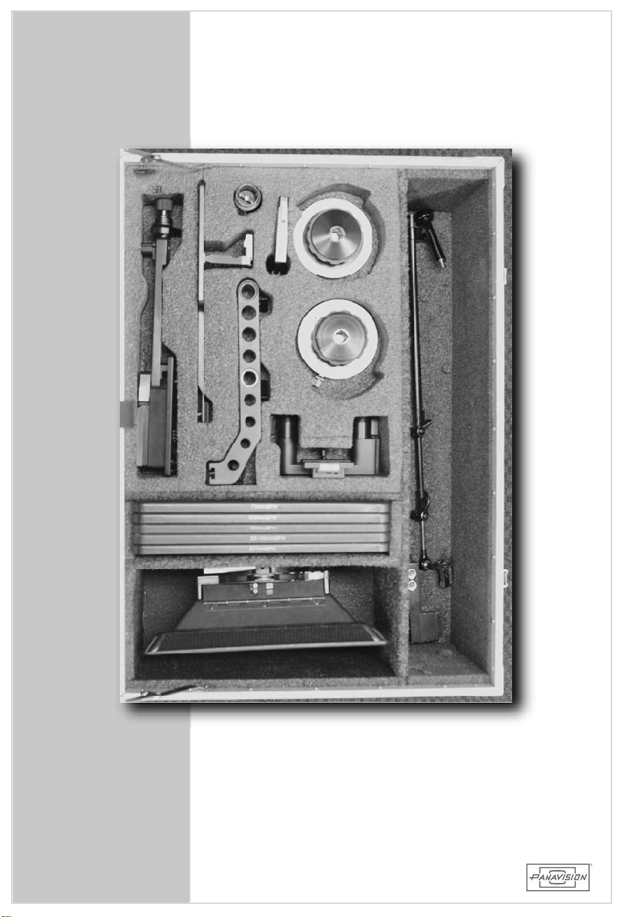
The accessorycaseholdsa4x5 swing awaymatte boxwith
mattes,sunshade,follow focus and knobs,Panavision
Steadicam
focusbracket,andsiderodadapter.
Clip-onpolarizermatteboxisoptional.
CASECONTENTS:
MFFGB ModularFollow FocusGearBox
MFFSK(2) ModularFollow FocusSingleSpeedKnob
MFFEX ModularFollow FocusExtension
FXHL OffsetHandle
FFX Follow FocusExtension12"
EPL-M EyepieceLeveler-Millennium
PLL PanaflexLensLight
HDLM HDLow-ModeBracket
HDSP HDSteadicam
HDRB HDRodBracket
CBLE-ZLP(2) Zoom LensPowerCable
IRISROD Pairof10"Irisrods
plates,eyepieceleveler,lenslight,whip,follow
Plate
HD900F
PACKING AND SHIPPING
27
2.2 ACCESSORYCASE
Page 28

28
Page 29
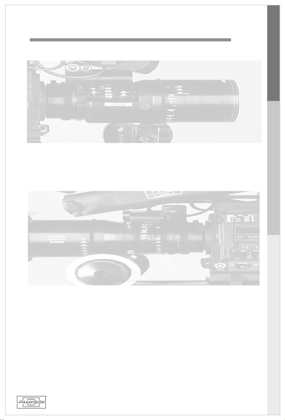
3.0 PRIMO DIGITAL™ LENSES
HD900F
PRIMO DIGITAL™ LENSES
3.0
29
Page 30
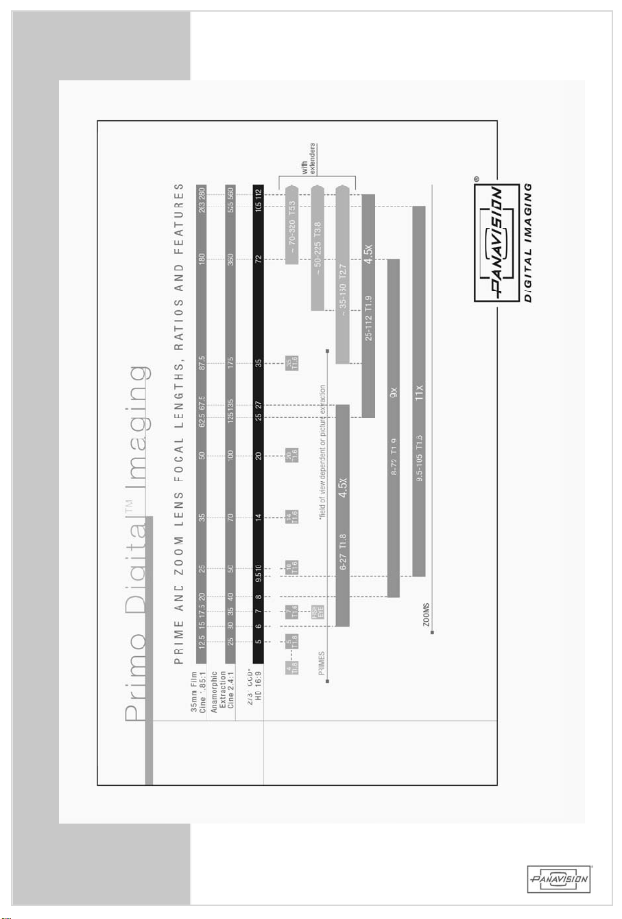
30
Page 31

3.1 PRIMO DIGITAL™ LENSDESIGN
PrimoDigital™ Lensesweredesignedspecificallyforthe
2/3”CCD imagerto optimizeimage quality. They are
notmodified cine lenses. However,Primo Digital™
primes and zoom lensesfully incorporate the optical,
mechanicaland ergonomiccharacteristicsofourPrimo
cinelenseswithadditionalfeaturestoenhanceelectronic
cinematography.
HD900F
• Highcontrastandresolutionformaximum sharpness. 2.5
timesthatofourcine Primo lensesto accommodate the
2/3”imagers.
• Optimized formaximum image quality atfastmaximum
apertures ofT1.6 – 1.9 (f1.45 – 1.75),thusenabling
depthsoffieldsimilarto35mm cineformats.
• Verylow veilingglare,ghosting,lateralcoloranddistortion.
• Dualexpanded,calibratedandaccuratefocusscales.
• Precision back focus adjustment– on alllenses including
DigitalPrimes.
• Internalfilterslot– to selectively controlcolorimetry and
resolution/contrast.
• Foruse with the SMARTLENS™ system,Panavision lenses
areavailable with integralencodersfordisplay offocus,
zoom andapertureposition.
PRIMO DIGITAL™ LENSES:
SD5 5mm T1.8PrimoDigital™ Prime 10½"CF
SD7 7mm T1.6PrimoDigital™ Prime 12" CF
SD10 10mm T1.6PrimoDigital™ Prime 12" CF
SD14 14mm T1.6PrimoDigital™ Prime 12" CF
SD20 20mm T1.6PrimoDigital™ Prime 13" CF
SD35 35mm T1.6PrimoDigital™ Prime 20" CF
SDZW 6-27mm T1.8PrimoDigital™ Zoom 22" CF
SDZT 25-112mm T1.9PrimoDigital™ Zoom 32" CF
SDZ9 8-72mm T1.9PrimoDigital™ Zoom 3' CF
SLZ11D 9.5-105T1.6PrimoDigital™ Zoom 4¼' CF
1.4SXD 1.4XextenderforPrimoDigital™ Zoom
2XSD 2XextenderforPrimoDigital™ Zoom
CDA DoubleAsphereAttachment,5mm =4mm
WFA WideAngleFisheyeAdapterfor7mm
PRIMO DIGITAL™ LENSES 3.1 PRIMODIGITAL™ LENSDESIGN
31
Page 32
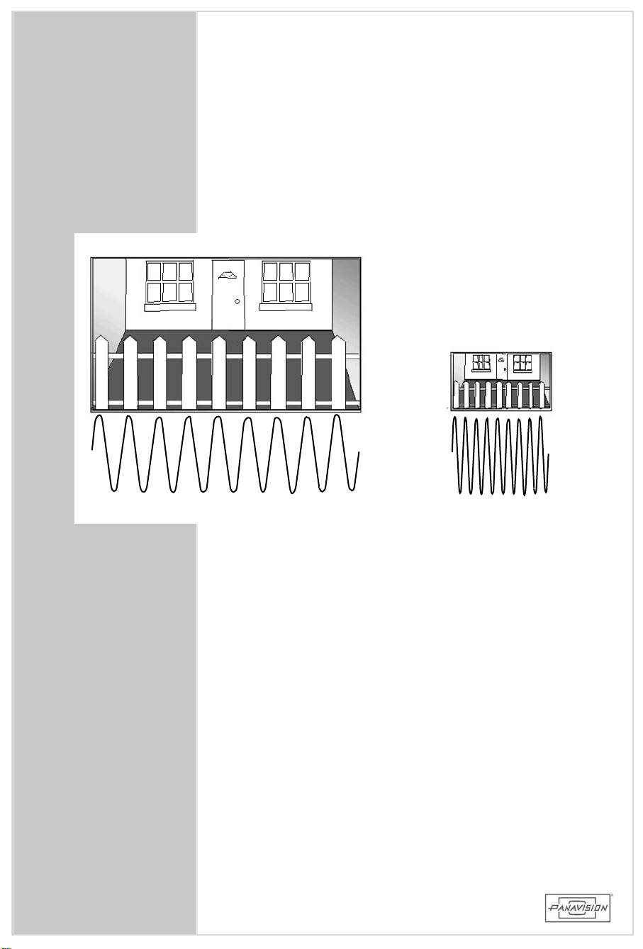
3perf16x9 35mm film area
2/3”HDCCD
32
20cycles/mm
50cycles/mm
Page 33

3.2 FILM /HD COMPARATIVERESOLUTION
The 2/3"CCD imagerisactually only11mm indiagonal
(asopposedtothe27.5mm diagonalofa35mm motion
picturefilm frame).Therefore,foranygivenscreensize,
the2/3"CCDwillrequire2.5timesmorehorizontalmagnification than a 35mm film frame. Thisrequired that
ournew PrimoDigital™ lensseriesbe designed to have
2.5timestheperformanceofourbestcinelenses. Allof
the new Primo Digital™ lensesprovide theiroptimum
performanceattheirmaximum aperture.
Ontheleftsideofthisgraphicisa16x9 format,35mm
film camera aperture. On the rightside isthe image
areaofa2/3"CCDdrawntothesamescale. Inorderto
havethesameperformanceasaPrimocinelens,Primo
DigitalTMlensesachieve80% contrastat50linepairsper
millimeteron the2/3"CCD (2.5 timesbetterfrequency
response).
HD900F
PRIMO DIGITAL™ LENSES
33
3.2 FILM /HDCOMPARATIVERESOLUTION
Page 34
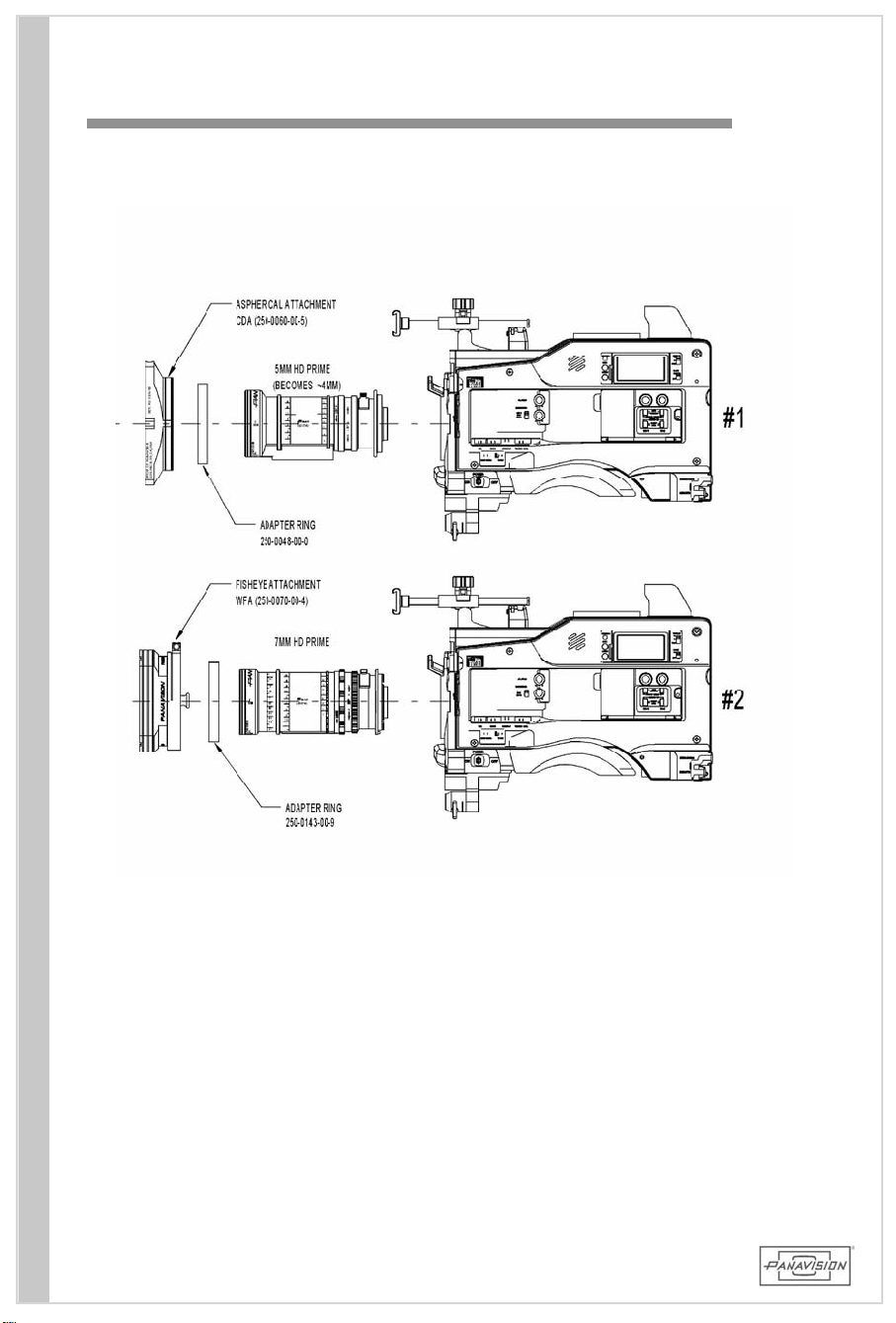
3.3 ASPHERICALAND FISHEYEATTACHMENTS
34
34
Page 35
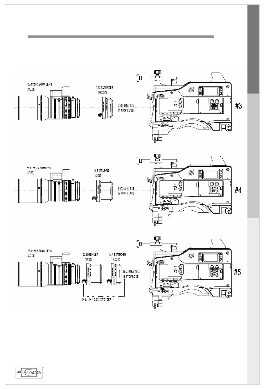
3.4 PRIMO DIGITAL™ LENSEXTENDERS
HD900F
PRIMO DIGITAL™ LENSES
35
3.3/4 ATTACHMENTS&EXTENDERS
Page 36
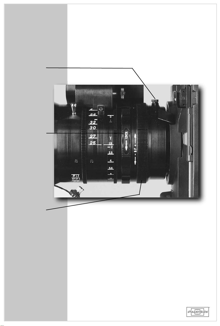
INTERNAL
FILTER
SLOT
BACK
FOCUS
LOCK
BACK
FOCUS
ADJUST
RING
36
Page 37

3.4 SETTING BACKFOCUS
In orderto gain themaximum performancefrom any
lens,itisnecessary thatback focusbe adjusted.
Usingalensthatisnotproperlyadjustedwillresultin
soft(outoffocus)images. While lensesformotion
pictureshaveafixed backfocusthatisadjustedbya
servicetechnician,lensesforvideoemployan integral
adjustmentthatissetbytheuser.
W ARNING : Be aware that extreme temperature
changescanaffectcameraparameters
suchasblackbalance andback focus.
Check the lenses afterevery lens
change and afterthey have “warmedup”on the camera. Also,you MUST
checkand/orreadjustbackfocuswhen
switchinglensesondifferentcameras.
Settingbackfocusisasimpleprocessandonceafew
stepsarepracticed,itcanbeperformedquickly.
HD900F
PRIMO DIGITAL™ LENSES
Testequipment:
Itis helpfulto have a chartthatcontains high
frequency (fine verticallines)information. Asan
alternative,look ata flatsubjectwith fine detail
(newspaper)andhighcontrast.
Ifyouhaveawaveform monitorontheset,observea
properly focused image in the green channel. You
shouldfindthisanaidtofindingthepropersetting.
Ifyouwillbejudgingfocusfrom amonitor,the24”is
best.The14”willsuffice,butdonotusea9”monitor
forthisprocedure.
The following steps describe the procedure forboth
zoom andfixedfocallengthlenses.
3.4 SETTINGBACKFOCUS
37
Page 38

38
Page 39

3.4 SETTING BACKFOCUS
Zoom lenses :
1. Set up a chart or flat test subject at around 4 – 6 feet from the focal
plane.
2. Open the iris to the MAXIMUM aperture (T1.8, etc.). Use the incamera ND filters if necessary.
3. Set the zoom to the longest focal length (zoom in) and front focus
the lens for the sharpest image. At this point you will find it helpful
to adjust the camera viewfinder peaking control to a minimal amount
of peaking. This will show very fine focus changes. It is sometimes
helpful to turn off or lower the brightness on the viewfinder to
emphasize contrast. Practice by observing the peaking while racking
the follow focus slowly to find the sharpest point (peaking just on).
4. Now, set the lens to the WIDEST focal length (zoom out).
5. Unlock the back focus lock. This is the ring located in front of the
back focus adjustment ring.
6. Move the adjusting ring slowly while observing the viewfinder
peaking, or the wavef orm monitor, or the picture monitor (24”
preferably) for the best focus. Look at the finest detail that you can
discern.
7. Again, set the lens to the maximum focal length (zoom in) and front
focus for the sharpest image.
8. Zoom wide. If image is not sharp at the wide end, repeat step 4
above and adjust back focus (per step 6).
9. Lock back focus ring, making sure not to move back focus
adjustment.
10. Double-check the lens after securing the lock. You should be able to
zoom in, f ront focu s and then zoo m wide and main tain focus
throughout the focal range.
11. Confirm the distance scale on the front focus ring by placing the chart
at measured distances and checking the engraved scale.
HD900F
PRIMO DIGITAL™ LENSES
3.4 SETTINGBACKFOCUS
Fixed focal length lenses:
1. Set the chart and the lens at a precisely measured close distance
that coincides with an engraved mark on the focus scale. This mark
should be no closer than the minimum focus plus 6" and no further
than the ability to resolve fine detail on the chart.
2. Follow steps 2, 5, 6, and 9 above. Note: on wide angle lenses it may
be difficult to confirm the distance scale by eye due to the extreme
depth of field of a wide angle lens.
39
Page 40

40
Page 41
4.0 CAMERAASSEMBLY
HD900F
CAMERAASSEMBLY
4.0
41
Page 42
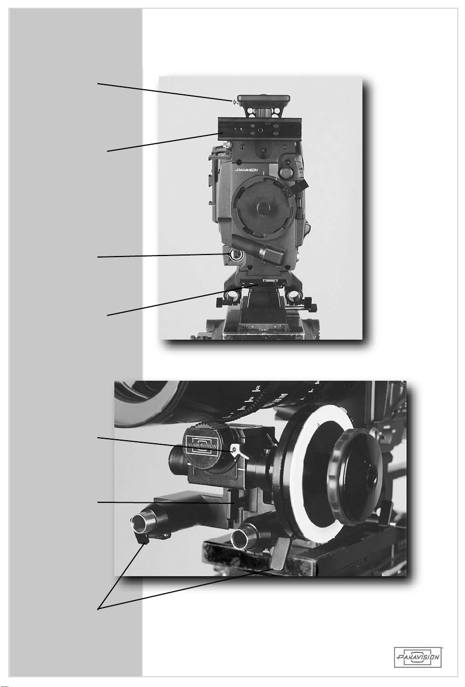
TAPE
HOOK
EYEPIECE
ANDACC.
DOVETAIL
MICIN
BASEPLATE
DOVETAIL
FOLLOW
FOCUS
LOCK
VERT.
ADJUST
LOCK
COLLET
LOCKS
42
Page 43

4.1 FRONTFACEPLATEAND FOLLOW FOCUS
FrontFaceplate
The frontofthe camera has been modified with a
Panavision HD LensMountand a redesigned and
strengthenedfaceplate. AproprietaryPanavisionbottom
dovetailhasbeen added tointerfacewiththebaseplate
system which includes 5/8"PV iris rod collets for
supportinglensesandholdingthefollow focusassembly.
Follow FocusAssembly
HD900F
CAMERAASSEMBLY
The follow focusbracketconsistsofan irisrod bracket
thatmountsontothebottom rodsandadovetailbracket
thatholdstheModularFollow Focus.
1.Slide the bracketassemblyonto therodsand adjust
foreandaftforcenteringtothelensfocusgear.
2.SlideMFFGearboxontodovetailfarenoughtolockit.
3.Then raisethefollow focusuntilitengagesthe lens
gearwith propergearmesh,and lock the vertical
adjustmentlock.
4.Fine tune gearbox position and lockfore /aftusing
irisrodcolletlocks.
Eachlenshasitsfocusgearatadifferentpositionsoyou
mustrepositionthefollow focusassemblywhenchanging
lenses. Thebracketassemblymustbemountedforward
enoughsothatthezoom pinclearsthegearbox.
4.1 FRONTFACEPLATE&FOLLOW FOCUS
43
Page 44
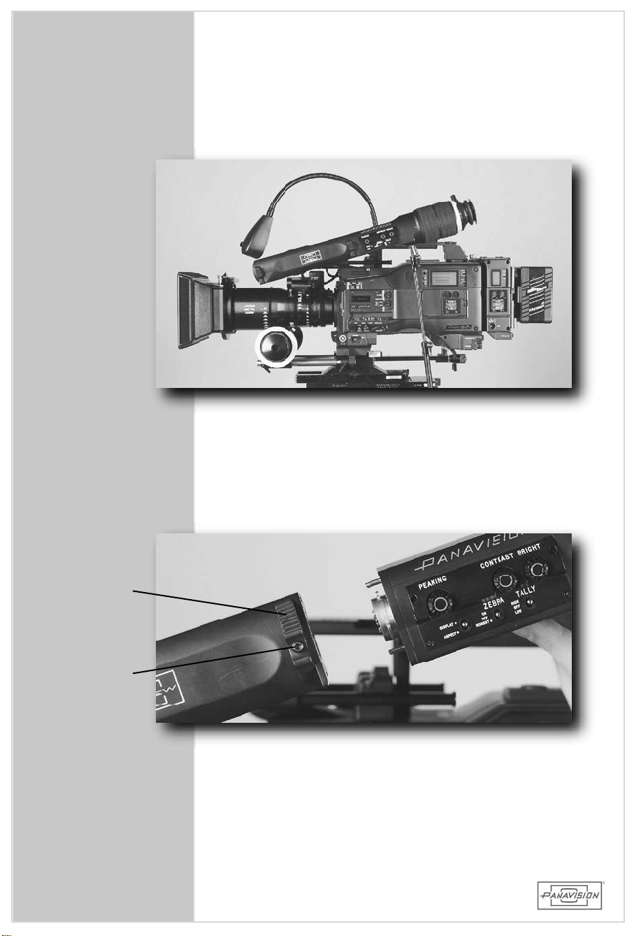
LOCK
LEVER
SAFETY
BUTTON
44
Page 45

4.2 VIEWFINDER
ThePanavisionULTRAVIEW®Eyepieceisconvertibleinto
two modesthatallow itto function asan extension
eyepiece,and an intermediate eyepiece /hand-held
eyepiece. Adjustmentsare provided forfore and aft
position ofthemountaswellassidetosideforlefteye
viewing.
Theviewfinderassemblyalsoincludesadditionalfeatures
suchasan extended diopterrangeand marking ring,a
Panacleareyecup and a 2x largerimage than astock
camera. The eyepiece retainsthe originalblack and
whiteCRT,buttheadjustmentcontrolsarerelocated to
the side. TheCRT isinterlace(seesection 1.8) which
showssome exaggerated blurand strobing thatisNOT
onthetape.
• Attachtheassemblyintothefrontdovetailsothatthe
eyepiece levelercan adjusteasily and lockin place.
Plug the cable into the connectorlabeled VF on the
tape side ofthe camera before turning on camera
power.
HD900F
CAMERAASSEMBLY
• When converting from extension to intermediate /
hand-heldmodeitisrecommendedtoturnoffthemain
powerswitchonthecamera.
• To convertthe viewfinderbetween its two modes,
depressthesafetybuttonandslidethelocklevers.
W ARNING: DO NOTrotatethefinder180 degreesto
theleft(torestitonthematteboxaswith
a film camera)as this willbreak the
internalstopsandwiring!
4.2 VIEWFINDER
45
Page 46
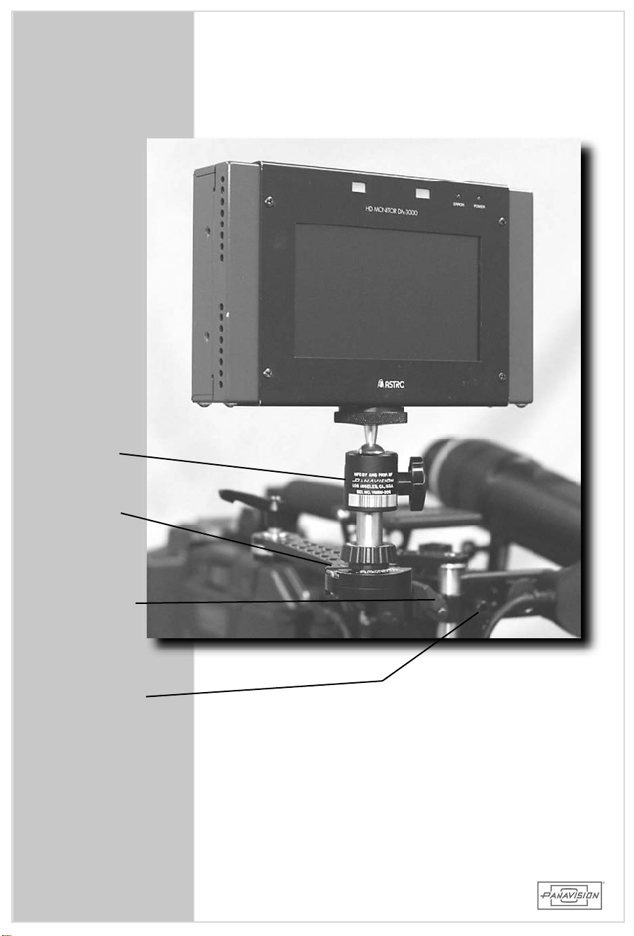
VMBM
MMBD
MONITOR
BRACKET
LOCK
MONITOR
DOVETAIL
LOCK
46
Page 47

4.3 ON-BOARD MONITORAND BRACKET
AstroHD Monitor
Slide the HD Auxiliary LightBracket(HDALB)into the
opposite side ofthe same dovetailthatthe eyepiece
attached onto. Then slide the DualModularMonitor
Bracket(MMBD)intothereceivingholeandlock.Mount
themonitorontoVideoMonitorBallMount(VMBM)with
the ¼-20 screw using eithertop orbottom mounting
holeonthemonitor. SlidetheBallMount(VMBM)onto
theMonitorBracket(MMBD).
The monitorcan sync to various rates by using the
selectorswitchontheback. Thestandardrateis24PsF
(for23.98PsF)
The monitoris12V DC ONLY using a 4 pin Hirose
connector,andispoweredfrom theUpconverter(HDUC)
with cableCBLE-AMPL,orfrom abeltbatterywithcable
CBLE-AMPX.
HD900F
CAMERAASSEMBLY
Themonitorhasthefollowingcontrolsandswitches:
• Chroma(on/off)
• Gamma(on/off)
• Center(centercross)
• Frame(16x9safezoneframeline)
• 4:3(transframeline)
• 2.4:1(2.40transframeline)
• Contrast
• Brightness
• B(bluewhitebalanceadjustment)
• R(redwhitebalanceadjustment)
• Chroma(adjustment)
VideoInputs:
HD SDIorY,Pb,Pr (analog)depending upon the
monitor.
NOTE:If using an NTSC monitor you must use a
downconverterinordertoconverttheHD signal
intoNTSC.
4.3 ON-BOARD MONITORAND BRACKET
47
Page 48
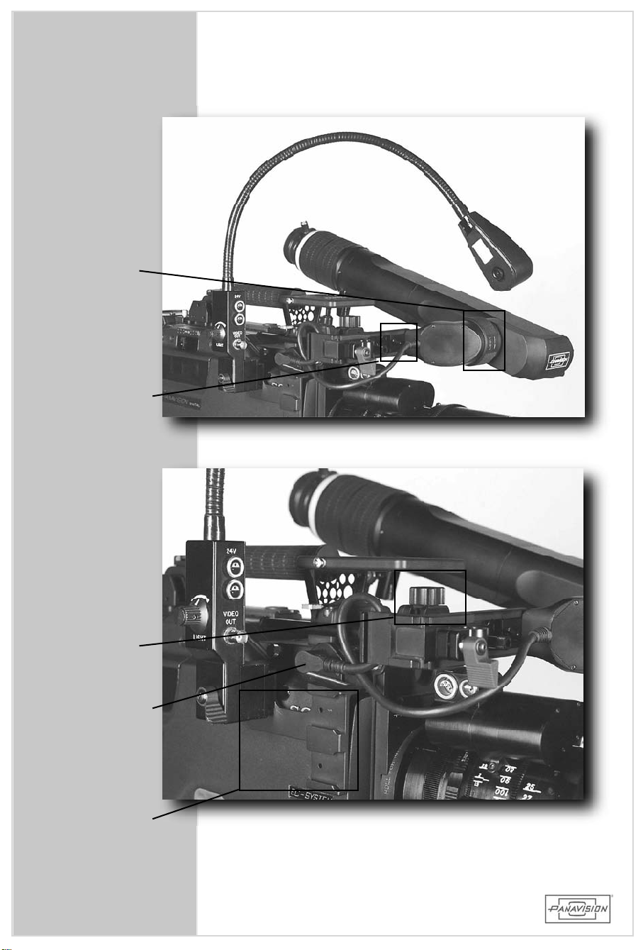
EYEPIECE
PIVOT
LOCK
EYEPIECE
DOVETAIL
LOCK
KNOB
EYEPIECE
FORE/
AFT
LOCK
EYEPIECE
CONNECT
ACC.
BRACKET
48
Page 49

4.4 LENSLIGHT
AnyPanavisionlenslightcanmountontoanyoftheside
orfrontdovetailson the camera. Justsupply power
from a24V DC source,eitherfrom a battery,the AC
powersupply orfrom the on-board powerconverter
(HDUC)thatcanattatchtothesideofthecamera.
NOTE:Although the 24p HD camera isa 12V DC (11-
17V)system,allofthestandard Panavision
accessoriesare still24V and need the proper
voltagetowork.
HD900F
CAMERAASSEMBLY
49
4.4 LENSLIGHT
Page 50
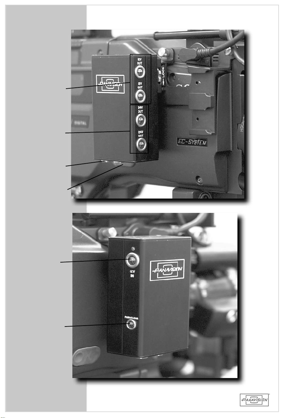
12V
OUTPUTS
24V
OUTPUTS
SMARTLENS
DISPLAY
SMARTLENS
INPUT
12V
INPUT
PANACLEAR
OUTPUT
50
Page 51

4.5 HD VOLTAGEUPCONVERTER
TheHD voltageupconverter(HDUC)provides224Vand
2 12V outputaccessory portsaswellaspowerforthe
Panaclearheated eyecup. The unitcan bemounted to
any ofthe dovetailson theside ofthe camera. In
addition,SMARTLENS™ inputand display outputports
areprovided.
The HDUC receives powerfrom eitherthe Sony
Upconverter(ABSU orABGM)withcableCBLE-ABSU,or
aCBLE-12PUC"Y"cablefrom a12Vbattery.
HD900F
CAMERAASSEMBLY
51
4.5HD VOLTAGEUPCONVERTER
Page 52
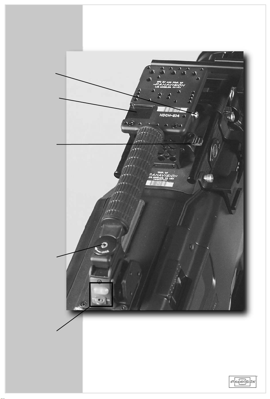
TAPE
HOOK
REMOTE
CONTROL
MOUNT
FRONT
RELEASE
LEVER
REAR
LOCK
TALLY
LIGHT
AND
SWITCH
52
Page 53

4.6CARRYHANDLE
Thiscustom Panavision carry handle isremovable and
replaceable with the Panavision SteadicamLow Mode
Bracketprovidedintheaccessorycase.
Simplyunlocktherearthumbscrew andpushdown on
the frontleverto allow the bracketto slide rearwards.
ReplaceandlockintotheSteadicam
The handle also hasa provision to mountthe Remote
Control(HDRP). Below therearend ofthehandleisa
tallylight(withon/offswitch)thatallowstheoperator
orcam era assistantto see when the camera is
recording. There are also red LED lights in the
viewfindertoindicatethesame.
Plateprovided.
HD900F
CAMERAASSEMBLY
53
4.6CARRYHANDLE
Page 54
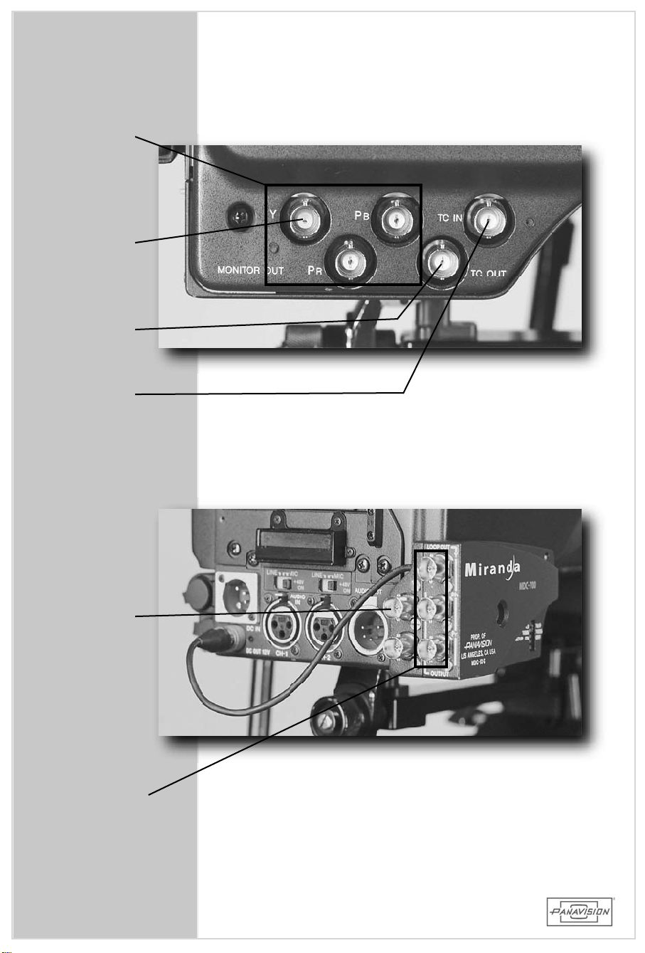
ANALOG HD
Y,Pb,Pr
OUT
GENLOCK
OUT
TIME
CODE
OUT
TIME
CODE
IN
NTSC
COMP.
OUT
ANALOG HD
LOOPOUT
54
Page 55

4.7 SIDEPANELCONNECTORS
Ontherearofthe tapeside ofthecamera there are5
BNCconnectors.
ThreearetheHDanalogcolordifferenceoutputs–Y,Pb,
Pr. Theseare usedto send an analog HD signalto a
monitor. Theycanalsobeusedtodisplaytheviewfinder
charactergeneratorimageouttoanexternalmonitorfor
convenientviewing.Thisisdoneby:
HD900F
• Hold down theMENU switchto the“cancel”position
with yourlefthand asyoupushthe DISPLAYswitch
downtothe“menu”position.
TheotherBNCsareforTimecodeINandTimecodeOUT
4.8 MIRANDADOWNCONVERTER
The Miranda on-board downconverter(MDC)converts
thecamera’sHD analogcolordifferencesignal(Y,Pb,Pr
on the side ofthe camera)into a standard definition
NTSCcompositesignal.
ThisallowstheNTSC video imageto bedisplayed ona
Steadicam
externalmonitors,orbe used on any standard video
device–monitors,VTRs,videoplaybacksystems,etc.
monitor,be wirelessly transmitted to
CAMERAASSEMBLY
4.7/8 SIDECONN.&MIRANDACONVERTER
Simply attach the downconverterto the three BNC
connectorson thesideofthecamera and lockwith the
screw. Connectthe powercable to the 4 pin Hirose
connectorthatsupplies12VDCOUTofthereartopower
the unit. Then attach a BNC cable to the COMP
connectoron the downconverterto anyNTSC standard
definitiondevice.
55
Page 56
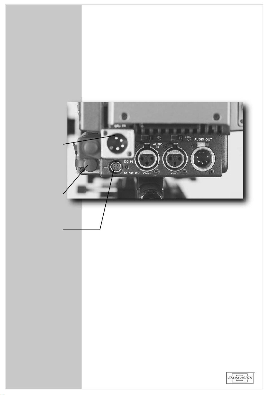
12VDCIN
REMOTE
12VDCOUT
(MIRANDA)
56
Page 57
4.9 REARPANELCONNECTORS
Ontherearpanelofthecameraarethepowerandaudio
connectors.Seesection1.2forspecifications.
• 4 pin powerIN connectoraccepts a standard 4 pin
XLRfemale.
• REMOTE connector that connects to an external
“Paintbox”(RMB150orCNU500).
• 4pinHirose–12VDCOUT(verylimitedcurrent(2A)
–onlyusefortheon-boarddownconverter)
• 3pinXLRAudioIN connectors(2)-switchable
• 5pinXLRAudioOUTconnector
W ARNING: Externalcamera controlbox willoverride
menu settings. When disconnected the
camerawillretainthechanges.
HD900F
CAMERAASSEMBLY
NOTE: Camera operating voltage range is 11-17 volts.
Nominalcamera powervoltage is13.2 or14.4
volts.
4.9 REARPANELCONNECTORS
57
Page 58
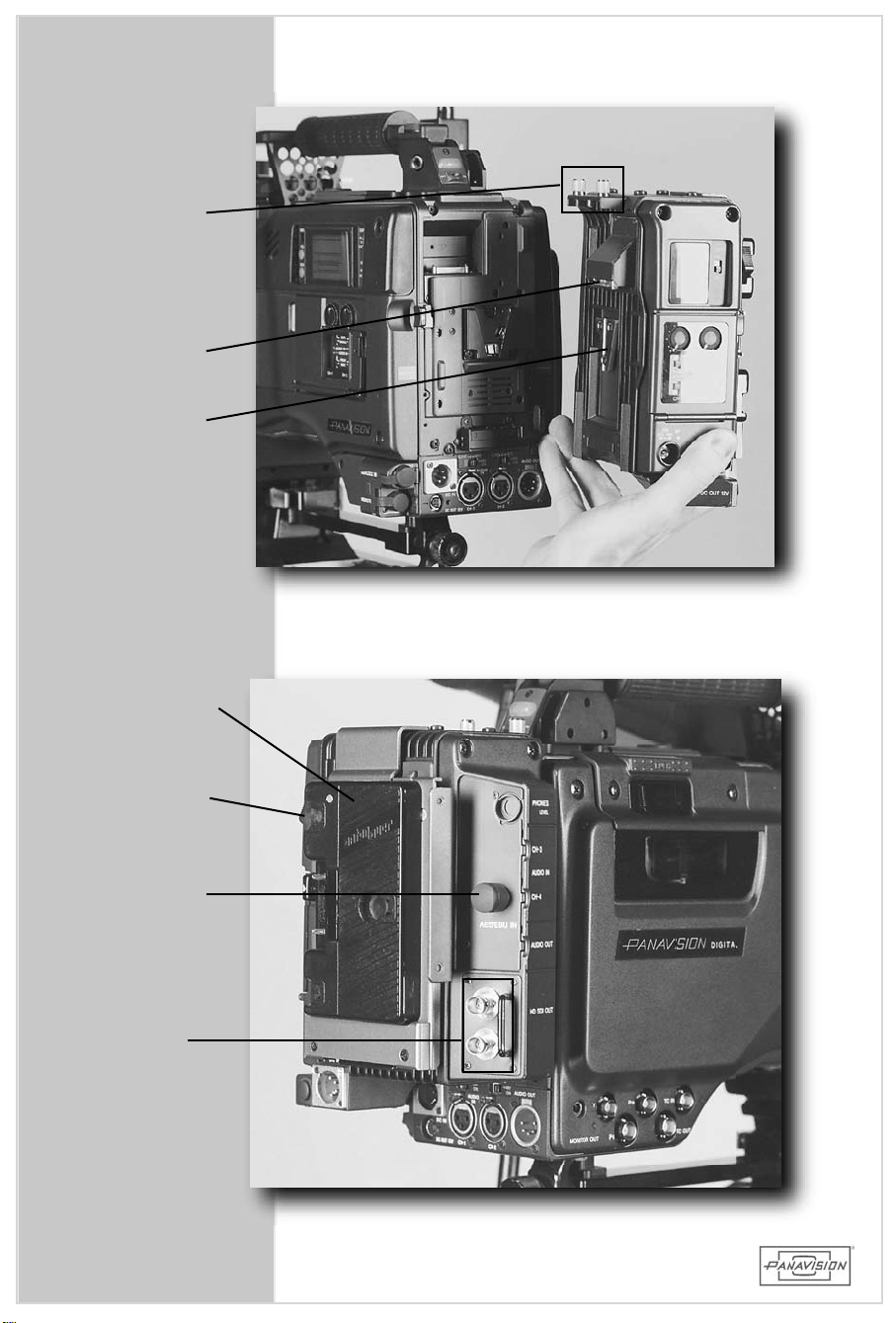
LOCK
SCREWS
ENGAGE
CONNECTOR
AND
DOVETAIL
ON-BOARD
BATTERY
ADAPTER
BATTERY
RELEASE
METADATA
IN
HDSDI
OUTPUTS
58
Page 59

4.10 HD SDIADAPTER
The HD SDIAdapter(HDCA orHDCAA)allows the
cameratooutputanHD SDIsignal. HD SDIstandsfor:
“HighDefinitionSerialDigitalInterface”. A serialdigital
signalisjustthat,aserialstream of1sand 0s that
representsthepictureinformation. Thedigitalsignalis
thenconvertedtoavideosignalbytheexternaldevices
(e.g.,monitors,downconverters,etc.) The SDIsignal
alsoincludestimecodeandaudio. Thisonecableisthe
mostusefuland convenientway to outputthe video
image.
Simply attach aheavy gauge 75 ohm BNC cable from
eitherofthe 2 outputsand then attachto an external
monitororotherdevice.
HD900F
CAMERAASSEMBLY
The SDIAdaptercan alsobe removed inordertoallow
the on-board downconverter to be attached for
Steadicam
NOTE:AnSDIAdapter(HDCAA)thatallows3rdand4
W ARNING: TheOn/Offswitchontheadaptermustbe
work–seesection4.7
th
audio tracks is available upon request. The
camera body itselfonly suppliesan HD analog
colordifferencesignal(Y,Pb,Pr).
oninordertofunction!
4.10 HD SDIADAPTER
59
Page 60
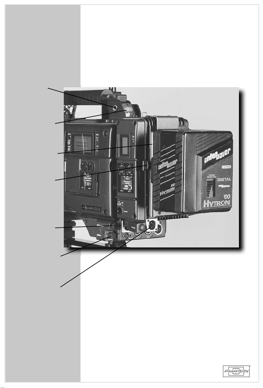
HEADPHONE
JACK
TALLY
LIGHT
BATTERY
RELEASE
ABSU
RELEASE
GENLOCK
IN
REMOTE/
PAINTBOX
(CNU connector)
12VDCIN
60
Page 61

4.11 ON-BOARDBATTERY
The Anton Baueron-board batterymounts onto the
adapterbracket(ABSU)thatattacheseitherontherear
ofthe camera body itselforon the HD SDIAdapter
(HDCAorHDCAA).
HD900F
TheAntonBauerbatteriesare14.4VDC,7AH rated,and
arechargedonaquickchargerstationthatallowsupto
4batteriesto chargein orderoneafterthe other. The
chargeralso has a built-in provision forbattery
discharging and analyzing to insure long battery life.
Eachbatteryhasabuilt-in12.5amp/125voltfuse.
NOTE:Camera operating voltage range is 11-17 volts.
Nominalcamera powervoltage is13.2 or14.4
volts.
CAMERAASSEMBLY
4.11 ON-BOARD BATTERY
61
Page 62

62
Page 63
5.0 CAMERAOPERATION
HD900F
CAMERAOPERATION
5.0
63
Page 64
64
Page 65

5.1 HDCAM CASSETTE
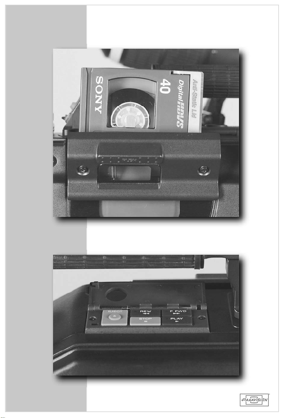
The HDCAM cassette loadsasshown with the window
facing up and the tape coverfacing toward the lens.
The ejectbutton is on top ofthe camera exposed
through the circularhole ofthe VTR controlcover.
Simply pushthe cassette down untilitseatsand then
closethe coveruntilitclicks. Aswith anytape,after
recording itissensibletopushintheredrecord protect
tabonthesidetopreventaccidentalre-recording.
Upon insertion ofa new tape,resetthe CTL track.
Then resetthe timecode track(ifusing R-Run)to zero
and using the“Hour”numbersetacamera rollnumber
forthattape. Recordcolorbarsandtoneatthehead
forfutureuseinpost.
Seesection5.7formoretimecodeinformation.
HD900F
CAMERAOPERATION
5.2 VTRCONTROLS
Use thesestandard VTR controlsto play,rewind,fast
forward,stopandejectthetape.
Youcanview theimageintheviewfinderoronamonitor
thatisconnectedtothecamera.
5.1/2 HDCAM CASSETTEANDVTR
65
Page 66
66
Page 67

5.3 VIEWFINDERCONTROLS
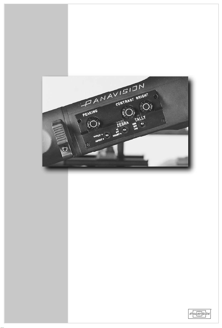
• PeakingKnob
Used to emphasize edge frequenciesin theviewfinderto
judgefocus.Helpfulwithsettingthelensbackfocus.
HD900F
• ContrastKnob
Used to adjust the eyepiece contrast for comfortable
viewing. Itishelpfulto usethe internalcolorbarswhen
adjusting.
• BrightnessKnob
Used to adjustthe eyepiece brightness forcomfortable
viewing. Itishelpfulto usethe internalcolorbarswhen
adjusting.
• DisplayandAspectSwitch
Used to turn on and offthe two independentframeline
generatorsin theviewfinderthatare pre-programmedin
OPERATION MENU page3. Togglethesamedirectionfor
ONandOFFofeachframeline.
• ZebraPatternSwitch
Usedtoturnonandoffthezebrastripeexposurepatterns
thatarepreprogrammedinOPERATION MENUpage5.
CAMERAOPERATION
5.3 VIEWFINDERCONTROLS
67
Page 68
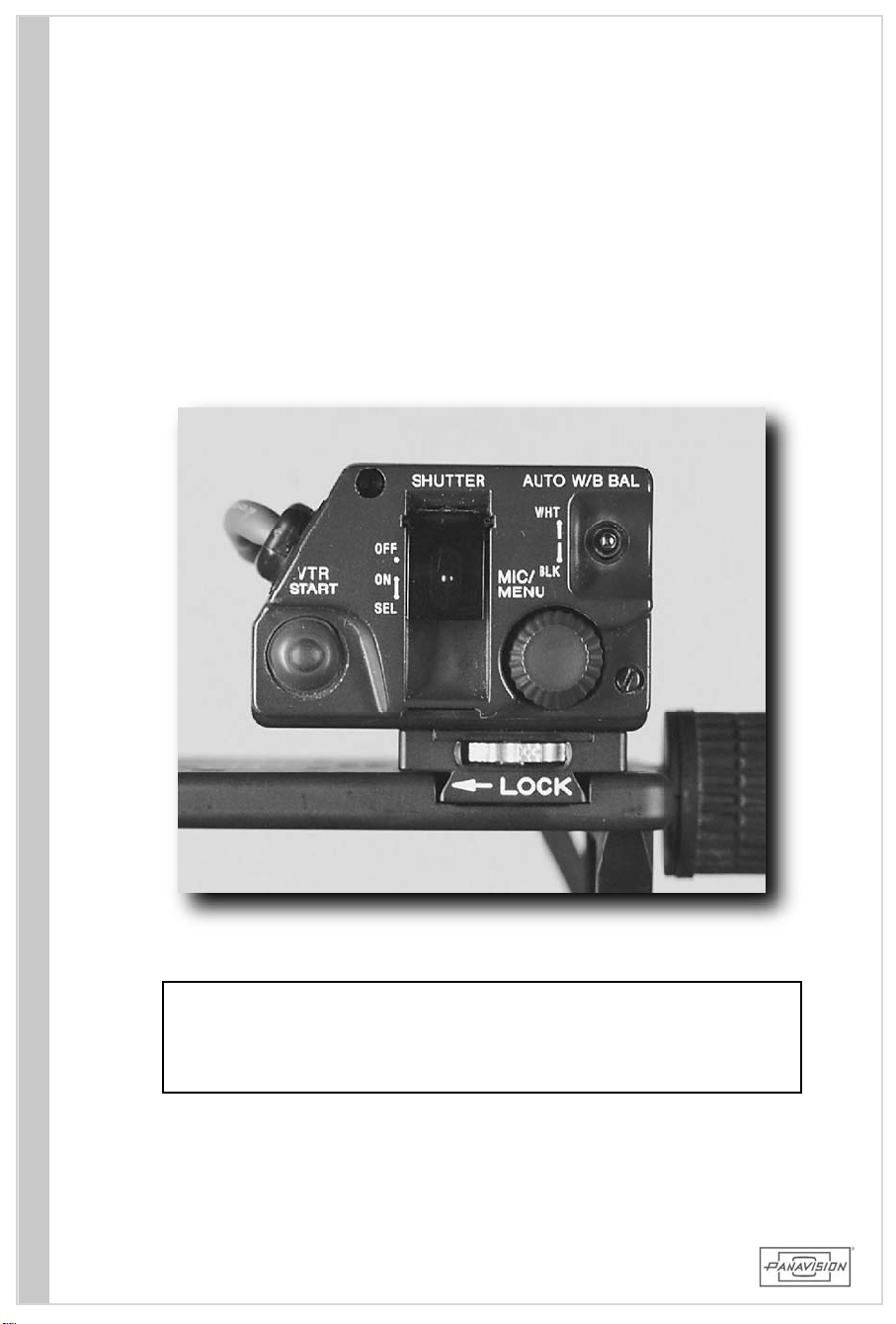
The originalcameraRemoteControlhasbeenredesigned
into a removable box whichconnectsto the 10pin Lemo
connectorlabeled "REM"on the side ofthe camera near
thePOWER Switch. Itcanmountontothe carryhandle
orberemoved whennotneeded(e.g.,for
handholding).
Steadicamor
68
68
W ARNING:Iftheshutterisswitchedoffonthisbox(HDRP)
andtheHDRPisdisconnectedfrom thecamera,
the camerawillautomatically return to the last
shutterONspeedselected.
Page 69

5.4 REMOTECONTROL
• RotaryEncoderWheel(MIC/MENU jogcontrol)
UsedtoenterandchangevaluesintheMENUS:
1. SettheDISPLAYswitchtotheMENUposition.
2. Clicktherotarywheeltoenteramenulistingortochangethe
cursorfrom anarrow intoa“?”.
3. Turningthewheelwhilethecursorisa“?”changesthevalueof
thatfield.
4. Clickingthewheellocksinthevalueandchangesthecursor
backintoanarrow thatcanbemovedwithinthescreens.
• VTR Start/StopSwitch
Usedasan“On/Off”switchfortherecorddeck.
• ShutterOn/Off/SelectSwitch
ThreepositiontoggleswitchsetselectronicshutterspeedeitherOff,
On and/orselectsthepresetvalues. In orderto view shutter
settingsin theviewfindertheDISPLAYswitchmustbeon. Shutter
speed canalsobe accessedthroughPAINT MENU page:P12. (See
section5.9.2)
• AW B -AutoW hiteBalanceSwitch
Usedtosetthewhitebalance:
1. Select the appropriate filter wheelfor the closestKelvin
temperatureofthelighting.
2. SelecteitherAorBswitchpositionontheWHITEBALswitchon
thesideofthecamera–thisisusedtosaveandmemorizethe
setting. (Itretains thevaluesunlessreplaced with another
setting.)
3. Setawhitereferencecard/papertothepropersize(atleast
70% offrame)and exposure and then push the switch to the
AWBpositionandletgo.
4. Confirm whitebalanceOKintheviewfinder.
5. IfwhitebalanceisNGselectthenextfiltersettingontheCC
filterwheelandtryagain,orre-checkexposure. Continuethis
processuntilOK.
HD900F
CAMERAOPERATION
NOTE: Perform anAWBasdesiredorneededforlightingconditions.Or
leaveWHITEBALANCEswitch on PRSTandtheCC filterwheel
on“B”.ThissetsthecameratoTungstenbalanceandshouldbe
colorcorrectedasrequired.
• ABB-AutoBlackBalanceSwitch
Usedtoperform anautoblackbalance:
1. Closethelensiristo“C”orcapittoensurenolightentering.
2. MakesuretheGAINisat0dB.
3. SettheDISPLAYswitchtotheONposition.
4. ClicktheswitchtotheABBpositionandletgo–itwillreturnto
themiddle.
5. Confirm “ABB:OK”inviewfinder.
NOTE:Perform anABB beforeshootinganduponextremetemperature
change from cold to hotconditions. Black balance resetsthe
blackset.
69
5.4 REMOTECONTROL
Page 70
70
Page 71

5.5 FILTERWHEELS
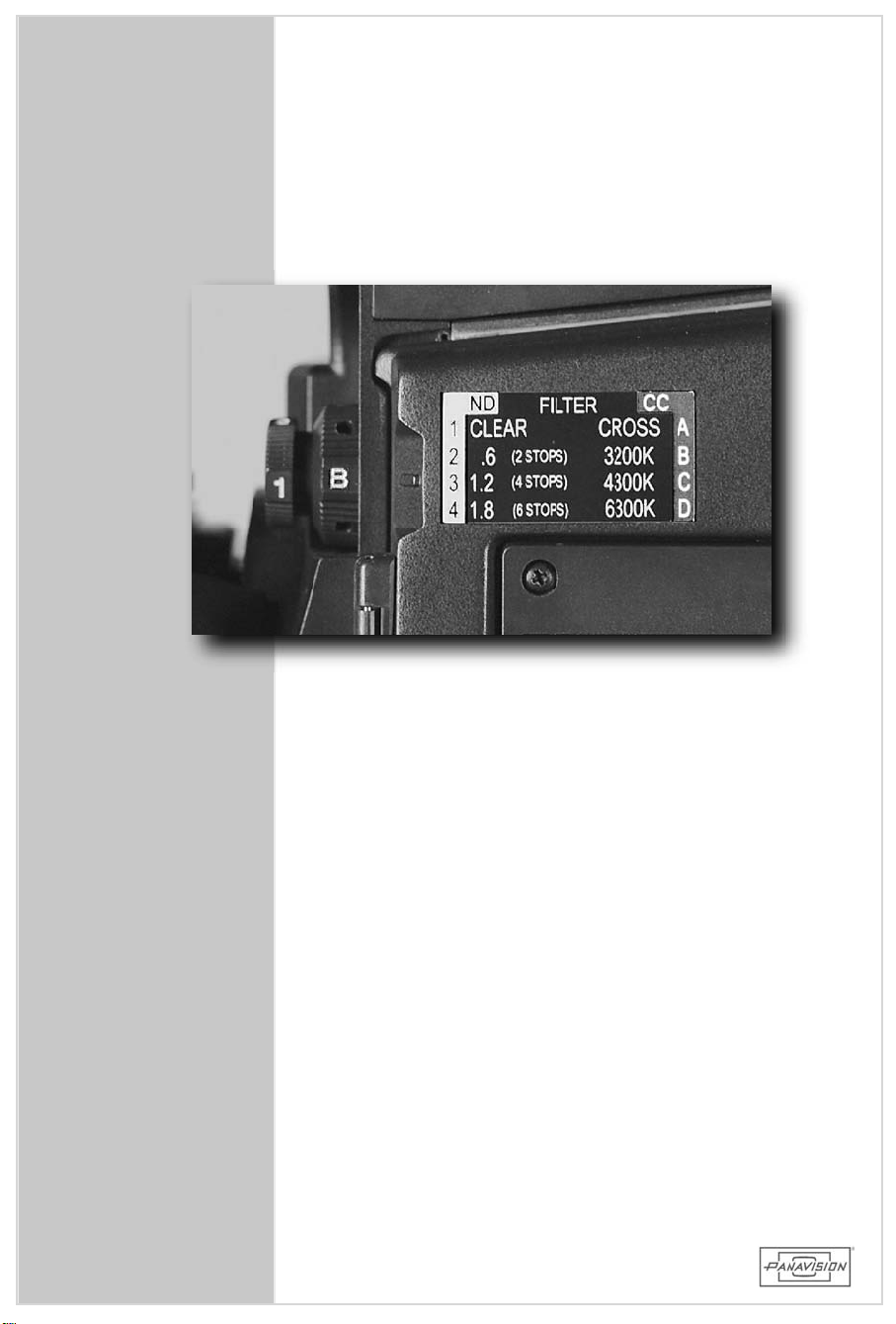
Internalfiltersforneutraldensity (CLEAR,ND .6,1.2,
1.8)and colorcorrection (3200K,4300K,6300K)are
builtintothesystem. Thesearemanuallyrotatedatthe
frontofthecamera.
W ARNING: Make sure filterwheelsarefirmlyintheir
detents.
HD900F
CAMERAOPERATION
71
5.5 FILTERWHEELS
Page 72
72
Page 73

5.6MEMORYSTICK
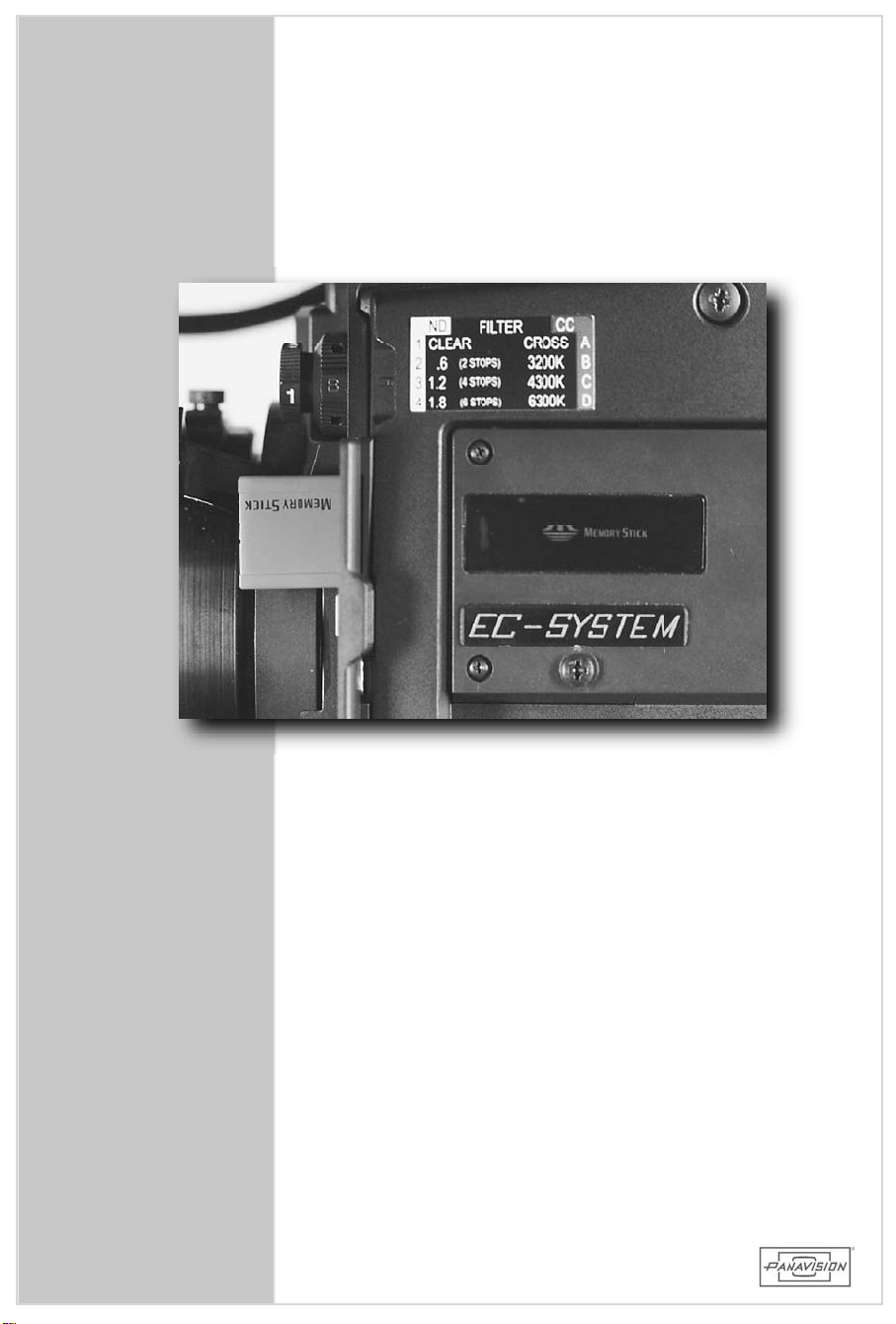
The camera usesthe standard Sony Memory Stickto
allow the userto save and recallthe OperatorFile
(OPERATION MENU page:9)andthe5PaintSceneFiles
(PAINTMENUpage:P13).(Seesections5.9.1,5.9.2)
HD900F
Simplyinsert thestickintotheslotunderthecoverdoor
withthenotchfacingupwardandthelabelfacingtoward
you.
NOTE: DO NOT ejectthe stick when the red eject
buttonislit. Thestickshavealocktoprevent
accidentalerasure.
CAMERAOPERATION
5.6 MEMORYSTICK
73
Page 74
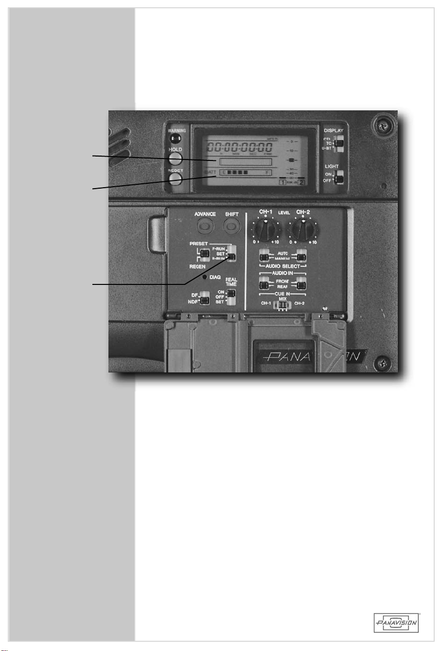
TAPE
COUNTER
BATTERY
LEVEL
F-RUN
R-RUN
74
Page 75

5.7 TIMECODE
You have twobasicchoicesfortimecode,eitherF-RUN
(“Free Run”)orR-RUN (“Record Run”). The choice of
whichto usedependsupon the requirementsforPost
Production.
HD900F
Using the R-RUN setting fortimecode isequivalentto
usingthefootagecounteronafilm camera. Itonlyrolls
whenthecamerarolls. TheScriptSupervisormayneed
torecordthetimecodenumberatthebeginningofeach
take.
FreeRun: Used when syncing the camera to an
externalsourceusing the TC IN connector
onthesidepanel. Thenumbersarealways
rolling.
RecordRun:Used with the camera’sinternaltimecode
generatorasthe sourceofthe timecode.
Itonlyrollsthenumberswhenrecording.
NOTE:The camera’s recorded timecode MUST be the
same asthe frame rate ofthe camera. For
example,iftrying to jam in 24 frame timecode
thecamera mustbesetto24PsFexactly– not
23.98Psf.
CAMERAOPERATION
5.7 TIMECODE
75
Page 76
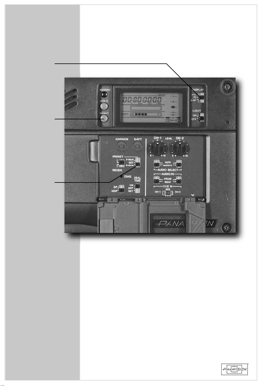
DISPLAY
SWITCH
RESET
F-RUN
R-RUN
76
Page 77

5.7.1 TIMECODESWITCHESAND BUTTONS
HOLD: Temporarily holdsthe F-Run display so itcan be
noted.Pushingagainreleasesit.
RESET: Resets the time data on the display – either
timecodeorcontroltrack.
DISPLAY: Selectswhichdatatodisplayinwindow.
CTL: ControlTrack
TC: Timecode
U-BIT: UserBits
ADVANCE:AdvancesthedigitselectedbytheSHIFTbutton
SHIFT: Selectsthedigittobechanged. Theselecteddigit
flashes.
PRESET/REGEN:
Selectswhethertosetanew timecodeortomatch
theexistingtimecodeonthetape.
HD900F
CAMERAOPERATION
F-RUN /SET/R-RUN:
Setstheoperatingmodefortheinternaltimecode
generator.
F-RUN: Timecodegeneratorkeepsrunning. Usedto
jam externalcodeintocameraorissettothe
“timeofday.”
SET: Allowsthetimecodetobesetusingthe
ADVANCEandSHIFTbuttons.
R-RUN: Timecodegeneratoronlyrunswhilerecording.
Usedwhennotjammingfrom anexternal
source.
DF/NDF: SetsDroporNon-Dropframecode. Usuallysetin
theNDFposition.
REALTIME: Selectswhetherornotrealtime isrecorded in
theVITCtrack
ON: RealtimeisrecordedasVITC.
OFF: Realtimeisnotrecorded.
SET: Usedtosettherealtime.
5.7.1 TIMECODESWITCHES&BUTTONS
77
Page 78
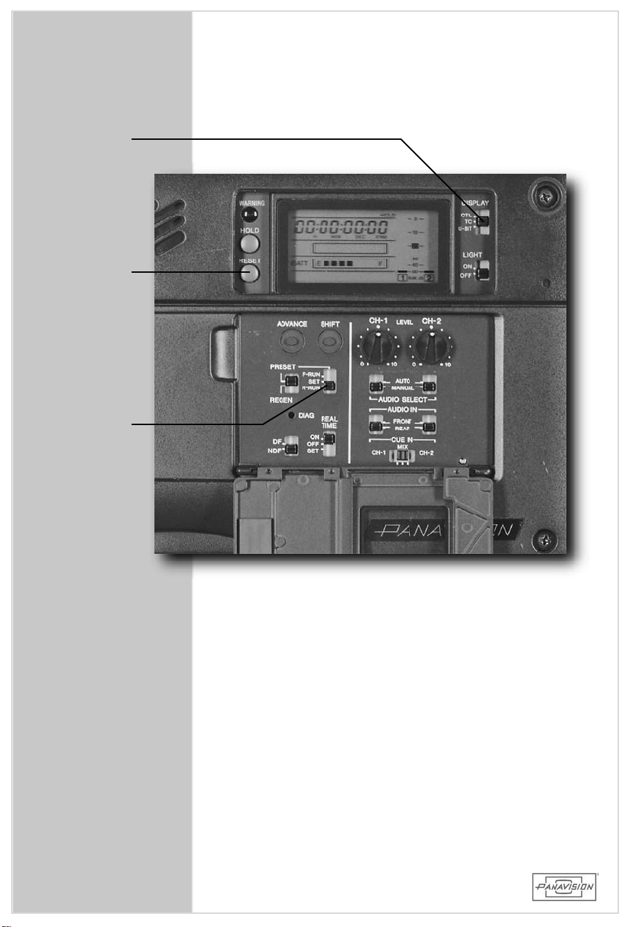
DISPLAY
SWITCH
RESET
F-RUN
R-RUN
78
Page 79

5.7.2 USING TIMECODE
SettingtheTimecode:
Witheachnew tapeyoumustresetthetimecodeifusing
R-RUNtimecode.
1. SettheDISPLAYswitchtoTC.
2. SetthePRESET/REGEN switchtoPRESET.
3. Setthe REAL TIME switch to ON or OFF (user
preference).
4. SettheF-RUN/R-RUNswitchtoSET.
5. PushtheRESETswitchtoclearthenumbers.
6. Using the SHIFT and ADVANCE buttons set the
“hours”numbertothe“rollnumber”thatyouwant
(usually startingat1andgoinguntil23 when you
have to use number1 again – butitwillbe a
differentday).
7. SettheF-RUN/R-RUN switchtoR-RUN (toactasa
footagecounterthatrunsonlywhenrecording).
(8.) Setthe F-RUN/R-RUN switch to F-RUN ifjamming
from anexternalsource.
9. SettheDISPLAYswitchtoCTLandpushtheRESET
buttontocleartheControlTrack.
10. Record ColorBars and Tone on the head ofthe
tape.
HD900F
CAMERAOPERATION 5.7.2 USING TIMECODE
RegeneratingTimecode:
Used aftera tape hasbeen ejected and reinserted to
makethetimecodecontinuous.
1. SetthePRESET/REGENswitchtoREGEN.
2. Use the tape transportcontrolbuttons to play back
(seesection5.2).
3. Watchingtheplayback,findtheendofthetapefrom
which to continue recording and pressthe STOP
button.
4. Press the ASSIGNABLE switch down toward #2 and
letgotodoarecordreview. Thiscuesupthetape.
5. Continuerecordingfrom there.
79
Page 80
80
Page 81

5.8 MAIN CAMERASWITCHES
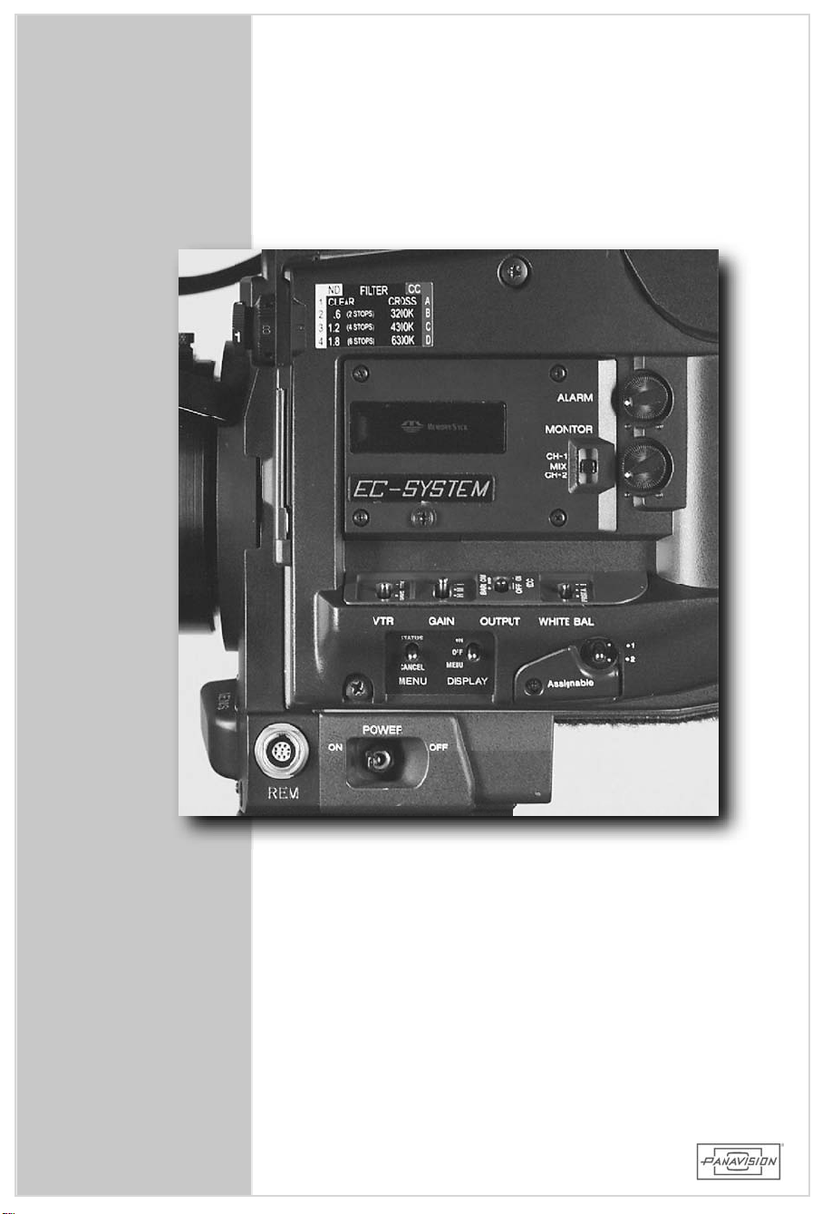
POW ER: This is the main switch that turns the
powerONandOFFonthecameraitself.It
isNOTaVTRrecordswitch.
W ARNING: SwitchthePOWERswitchtoOFFwhenever
changing cableson the camera orreconfiguring the viewfinderto prevent
possibledamage.
ASSIGNABLE:This switch is preprogrammed in the
OPERATION MENU page:8 to the
followingsettings:
#1 PushUPtorecord,pushUPtostop.
HD900F
CAMERAOPERATION
#2 PushDOWNtodoa“RecordReview” ofthe
last3 secondson the tape. Used to “Check
theGate” (Youmusthaverecordedatleast3
secondson the lasttake.) Alsoused when
regeneratingtimecode.(seesection5.7.2)
VTR: Changes the status of the VTR when not
recording from SAVE to STANDBY. The
recommended position isSAVE which saves
battery life and reduceswearon the record
head.
GAIN: Choosesbetweenthethree usersettable gain
positions. EitherL,M orH. These are
programmable from –3 dB to +18 in the
OPERATIONMENUpage:4.
NOTE: It is a standard practice to have L=0 dB.
Usingnegative(-)gainreducesdynamic
range.
5.8 MAIN CAMERASWITCHES
81
Page 82
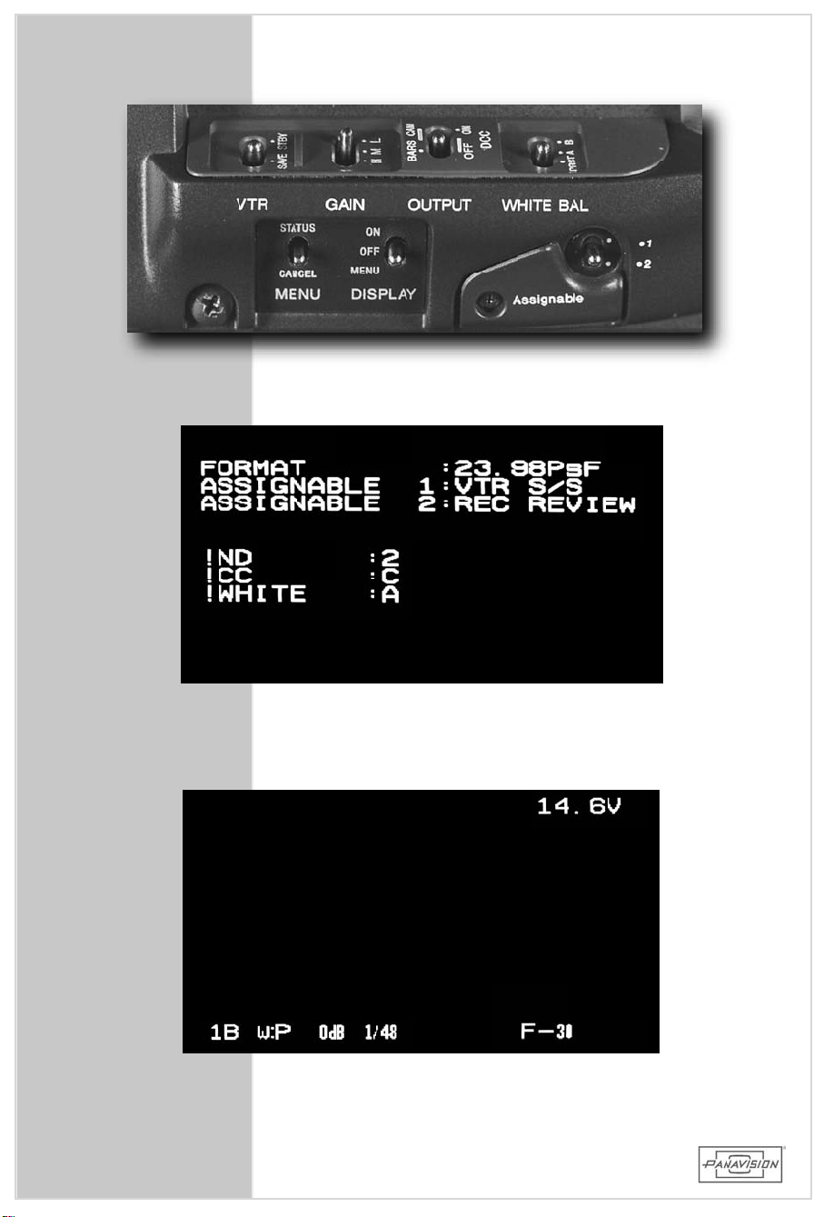
82
SampleviewfinderdisplaywhenMENUswitchheld
toSTATUSposition.SeealsoSection5.9.1
Sample viewfinderdisplay with DISPLAY switch in
ONposition.SeealsoSection5.9.1
Page 83

5.8 MAIN CAMERASWITCHES-CONTINUED
OUTPUT: Switches the outputsignalofthe camera
between colorbars,camera orcamera
withDCCon.
W ARNING: DCC is an autoknee circuit which will
adjust the highlights in the im age
depending on theirbrightness. (Also see
section1.9).
IftheDCC isswitchedonandthenoff,the
KNEEcircuitstillremainson!
W HITE
BALANCE: Sets the white balance of the camera
between eitherthe PRST (preset)orthe
twosavedswitchpositions–AorB.
HD900F
CAMERAOPERATION
Leaving the switch on PRST and the CC
filterwheelon B sets the camera to the
factory defaulttungsten white balance
whenusing3200Klighting.
MENU: Holding the switch up to the STATUS
position showsthe currentframe rate of
the camera in the viewfinderaswellas
warning indicationsand the programmed
settings ofthe ASSIGNABLE switch.
Pushingdown towardCANCELwheninthe
menuscancels a selection orreverses
orderthroughamenulist.
DISPLAY: Usedtoturnonoroffthepreprogrammed
DISPLAY indicatorsin the viewfinder(set
with OPERATION MENU page:1)orto
enterintotheMENUsofthecamera.
See Section 5.9 for description of the
MENUs.
5.8 MAIN CAMERASWITCHES-CONT.
83
Page 84
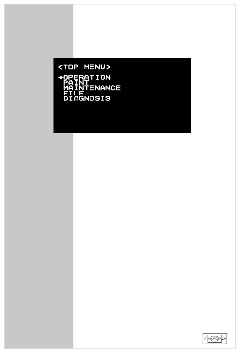
84
Page 85

5.9 MENUS
We willoutline the commonly usefulpages in the
OPERATIONandPAINTmenus.
UsingtheMenus
HD900F
1. Setthe DISPLAY switch to the MENU position and
lookintheviewfinder.
2. Move the arrow cursor opposite the menu to be
displayedandpushinontheRotaryEncoderWheel.
3. To change pagesin the menu,setthe cursorto the
page number,clickthe Wheelto makethe cursora
“?”andturntheWheeltochangepages.
4. Tochangeasettingvalue,setthecursortotheitem
tobechangedandpresstheWheel. Thecursorturns
into a “?”and the value changes by turning the
Wheel.(Afastturnchangesthevaluegreatly,aslow
turn changesitslightly.) To lockthe change press
the Wheelagain. To cancela change,pressthe
MENUswitchtotheCANCELposition.
5. Every click of the MENU switch to the CANCEL
positionwillrevertuponemenulevel.
6. To exitfrom the MENUs,turn the DISPLAYswitchto
OFF.
7. When re-entering into the MENUs the camera will
displaythelastmenupageused.
NOTE: Ifthe TOP MENU listdoesnotshow when you
settheDISPLAYswitch totheMENUpositiondo
thefollowing: ReturntheDISPLAYswitchtothe
OFFposition. Thenhold IN theRotaryEncoder
WheelontheRemoteControlwhile yousetthe
DISPLAYswitchtotheMENUposition.
CAMERAOPERATION
5.9 MENUS
85
Page 86
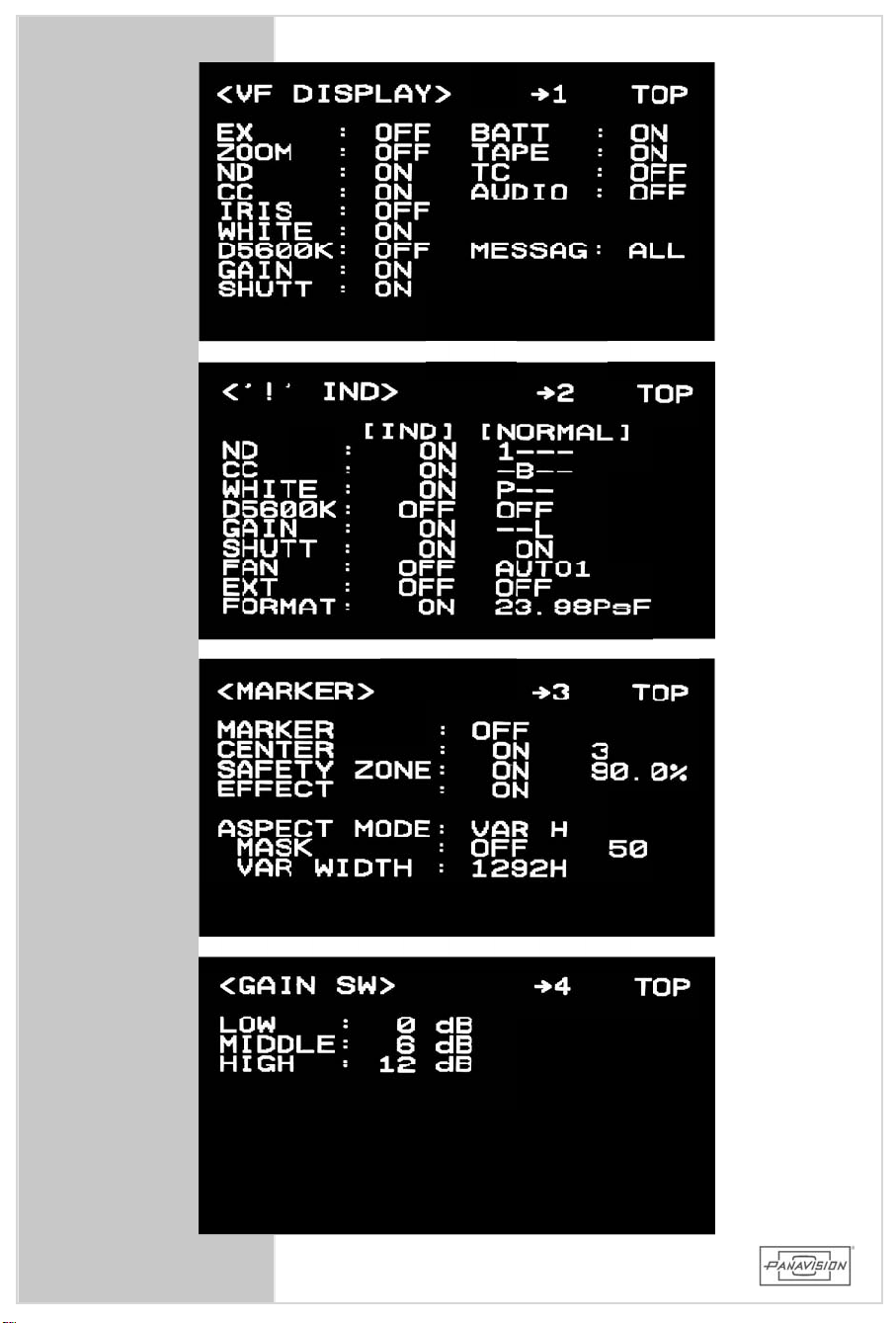
86
Page 87

5.9.1OPERATION MENU
• The OPERATION MENU is used to set up various
attributesofthe camera. Theseattributesdo not
affectthe image captured by the camera directly,
unlikethePAINTMENU.
HD900F
1. VFDISPLAY
• UsedtoturnON andOFFdisplayindicatorsofvarious
attributesofthecameraintheviewfindersuchasND
and CC filterstatus,battery voltage,shutterspeed,
gain,whitebalance,andtaperemaining.
(PictureshowsPanavisiondefaultsettings.)
2. !IND
• Used to setthe warning indicators. Displayswhich
warningsare active by holding the MENU switch to
the STATUS position. Any camera setting that
changesfrom the[NORMAL]setting willturn onthe
“!”LED intheviewfinder.
(PictureshowsPanavisiondefaultsettings.)
3. MARKER
• Used to setthe2 framelinesin theviewfinder. See
section 5.10 fordetails. Turning the MARKER and
the ASPECT MODE in this menu isthe same as
togglingthem ON andOFFwiththeswitchontheside
oftheviewfinder.
(Picture shows example ofTV 16x9 TRANS & 4X3
TRANS/SAFE.)
CAMERAOPERATION
5.9.1 OPERATIONMENU
4. GAIN
• Used to program the three settings for the GAIN
switchon the side ofthecamera. Note: you can
setanyofthepossiblevaluestoanyswitchposition.
UsuallyL= 0. Thechoicesare: -3,0,3,6,12or18
dB.
(PictureshowsPanavisiondefaultsettings.)
87
Page 88
88
Page 89

5.9.1OPERATION MENU-CONTINUED
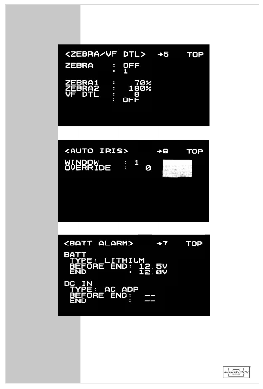
5. ZEBRA/VFDTL
• Usedtoprogram the2zebrapatterns.TheON /OFF
settinghereisthesameasthetoggleswitchon the
side ofthe viewfinder. The zebra patterns are
independentandcanbeusedseparatelyortogether.
• Thezebrapattern isaconvenientwaytojudgeyour
highlightexposure when a waveform monitorisnot
available.
(PictureshowsPanavisiondefaultsettings.)
6. AUTO IRIS
• Notused.
7. BATTALARM
• Displaysthelow andoutbatteryvoltagesettingsthat
are programmed in the MAINTENANCE MENU page:
M9.
(PictureshowsPanavisiondefaultsettings.)
HD900F
CAMERAOPERATION
89
5.9.1OPERATIONMENU -CONT.
Page 90
90
Page 91

5.9.1OPERATION MENU-CONTINUED
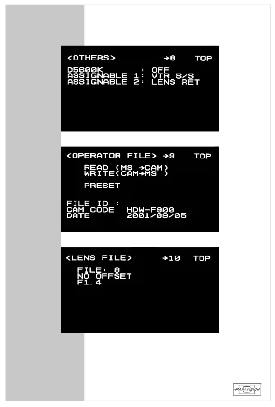
8. OTHERS
• Showsthe programmedsetting oftheASSIGNABLE
switch.
(PictureshowsPanavisiondefaultsettings.)
HD900F
9. OPERATORFILE
• UsedtoreadandwritetheOPERATION MENU fileto
andfrom aMemoryStick
10. LENSFILE
• Notused.
CAMERAOPERATION
5.9.1OPERATIONMENU -CONT.
91
Page 92
92
Page 93

5.9.2 PAINTMENU
• The PAINTMENU isusedtoadjustthe wayin which
thecameracapturesanimage.
CAUTION: Some im age adjustm ents are not
reversibleinpost.(Seealsosection1.9)
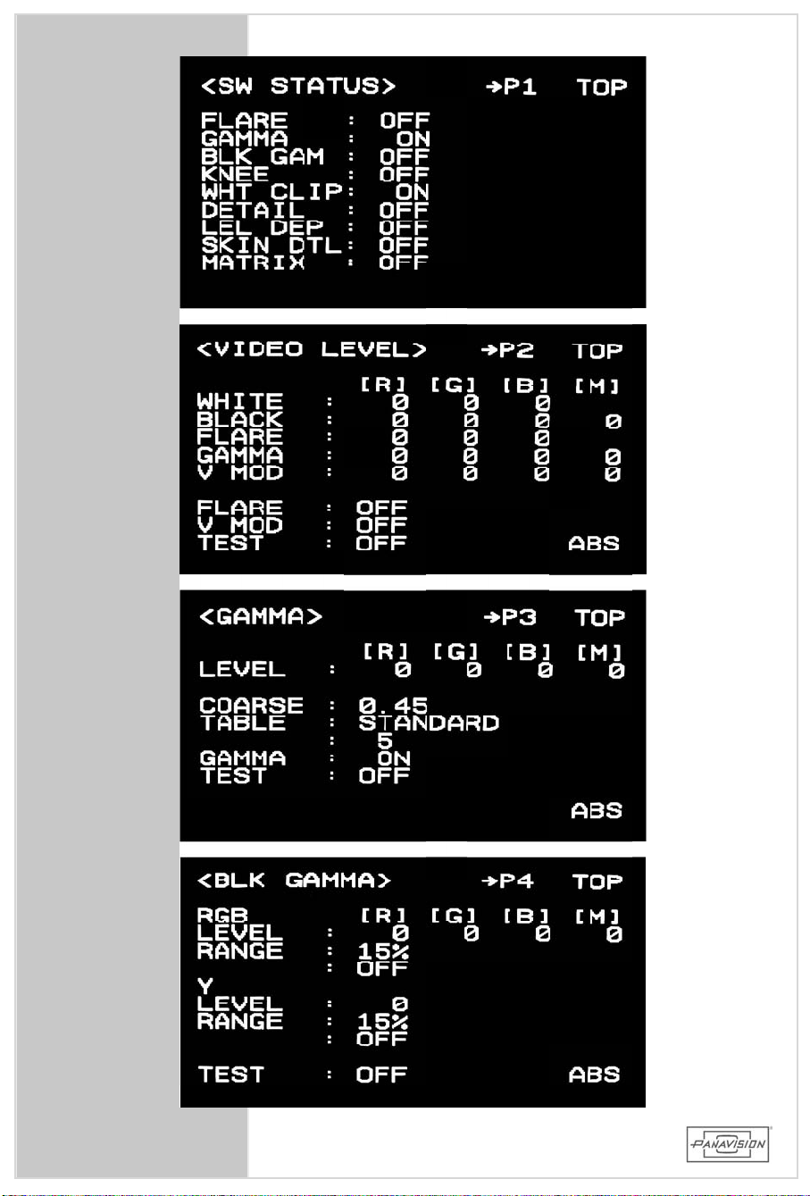
1. SW STATUS
• Used to conveniently turn ON orOFF various paint
switches.Theyareduplicatedinlaterpages.
(PictureshowsPanavisiondefaultsettings.)
2. VIDEO LEVEL
• Usedtomanuallysetawhitebalanceandblacklevel.
(PictureshowsPanavisiondefaultsettings.)
HD900F
CAMERAOPERATION
NOTE: The[M]BLACK levelisusuallysetto0or–1 so
thatthe video signalisbeing recorded just
abovecliplevelonthewaveform monitor.
3. GAMMA
• Used to adjustthe video GAMMA. Should be ON.
The normalsetting isCOARSE 0.45,STANDARD 5.
ThesesettingsreferencetheITU-709standard.
(PictureshowsPanavisiondefaultsettings.)
4. BLKGAMMA
• Used to adjustthe gamma in the black partofthe
picture.NominalsettingisOFF.
(PictureshowsPanavisiondefaultsettings.)
CAUTION: Changingtheblackgammacouldadversely
affectnoiseinthepicture.
5.9.2 PAINTMENU
93
Page 94
94
Page 95

5.9.2 PAINTMENU-CONTINUED
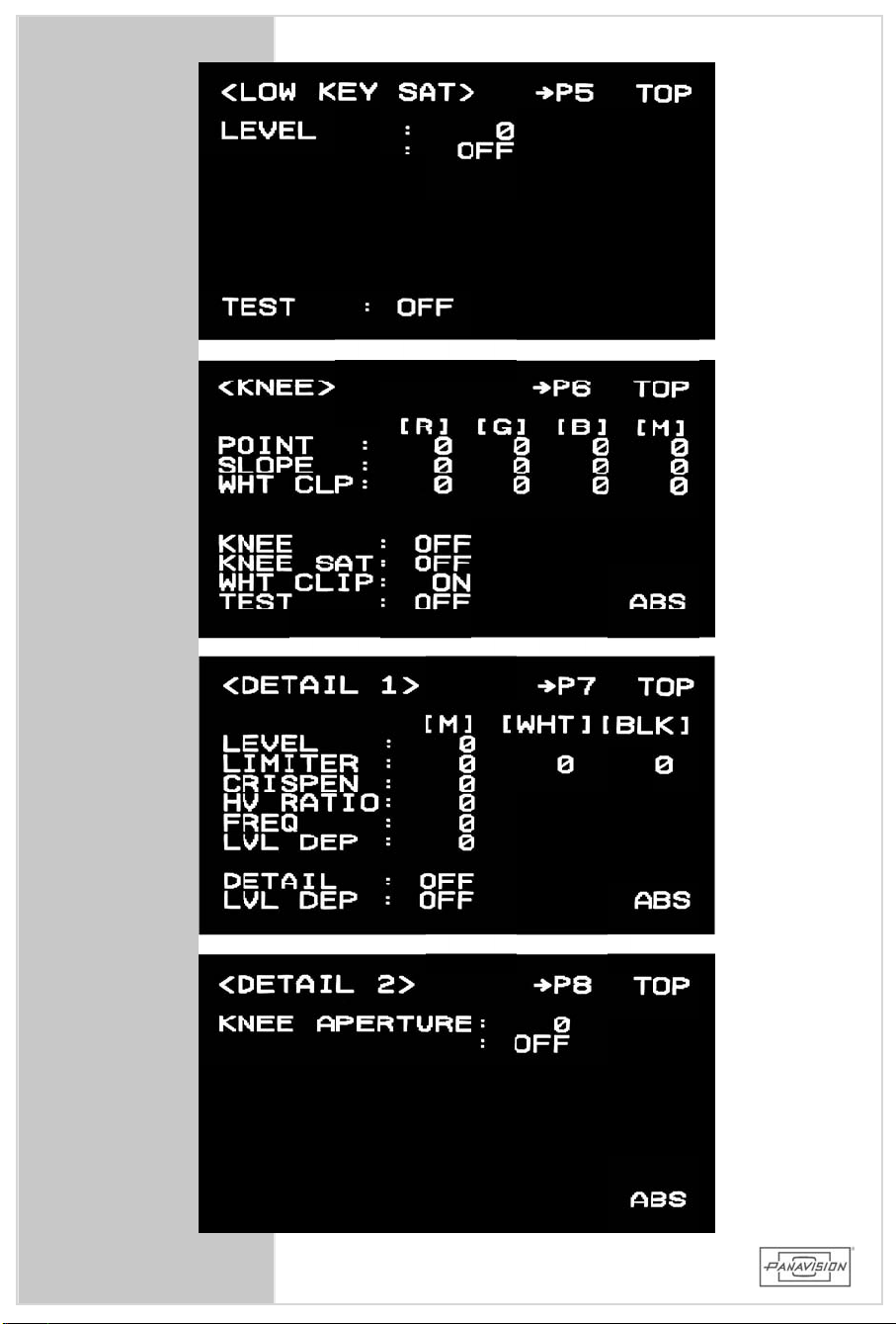
5. LOW KEYSAT
• Used to adjustthecolorsaturationinthe dark areas
ofthepicture.NominalsettingisOFF.
(PictureshowsPanavisiondefaultsettings.)
HD900F
6. KNEE
• Used to adjustthe highlightportion ofthe picture.
Useasdesired.UsuallyturnedOFF.
(PictureshowsPanavisiondefaultsettings.)
7. DETAIL1
• Usedforelectronicimageenhancement.
(PictureshowsPanavisiondefaultsettings.)
8. DETAIL2
• Usedforelectronicimageenhancement.
(PictureshowsPanavisiondefaultsettings.)
NOTE:Historically detailcircuits were used to
compensateforlimitationsofopticsor
electronics.
ThedetailcircuitsshouldNOTBEUSED sinceour
Primo Digital™ Lenseshave very high contrast
and resolution. Consequently there isno need
foradditionalelectronic detail,and the use of
detailcancauseunwantedartifacts.
CAMERAOPERATION
5.9.2 PAINTMENU-CONT.
95
Page 96
96
Page 97

5.9.2 PAINTMENU-CONTINUED
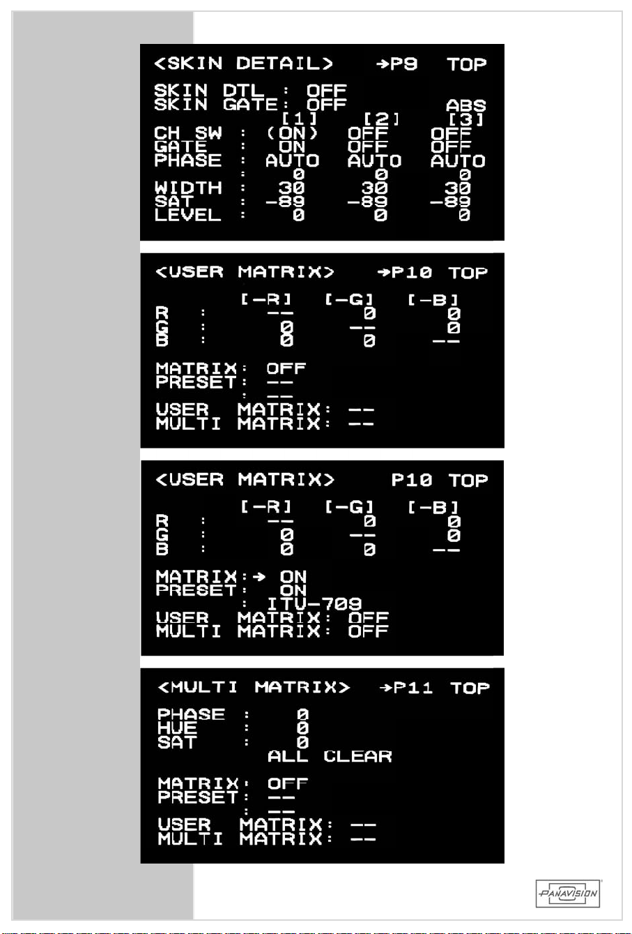
9. SKINDETAIL
• Disablesdetailcircuitryforspecifiedcolors.
(PictureshowsPanavisiondefaultsettings.)
HD900F
NOTE:ThiscircuitshouldNOTBEUSED sinceourPrimo
Digital™ Lenses have very high contrastand
resolution. Consequently there isno need for
additionalelectronicdetail,andthe useofdetail
cancauseunwantedartifacts.
10. USERMATRIX
• Used to setoradjustthelinearmatrixforanoverall
adjustmentofthepicture.
(Firstpicture shows Panavision default settings for
film-outorvideo finish. Second UserMatrixpicture
showsoptionforvideofinishonly.)
11. MULTIMATRIX
• Used to change specificvectorsofacolorand their
saturation.
(PictureshowsPanavisiondefaultsettings.)
W ARNING: DONOTusethematricesunlessyouknow
theexacteffectyouwant,sinceitisNOT
reversibleinpost.
CAMERAOPERATION
5.9.2 PAINTMENU-CONT.
W ARNING: IfthereisANYfuturepossibilityofthe
footagegettingrecordedouttoafilm
negativethenyoushouldshootwiththe
MATRIXturnedOFF. Iftheprojectwill
stayontapethenyoucanturntheMATRIX
ONwiththePRESETvaluesettoITU-709.
97
Page 98
98
Page 99

5.9.2 PAINTMENU-CONTINUED
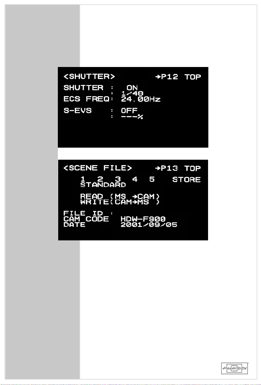
12. SHUTTER
• Used to adjustthe shutter speed of the camera.
Changing the valueshere isthe sameaswith the
toggle switchon the Remote Control. SeeSection
5.4.
(PictureshowsPanavisiondefaultsettings.)
13. SCENEFILE
• Used to read and write the 5 PAINT MENU SCENE
filestoandfrom aMemoryStick.
NOTE: TorestorethepaintmenustotheirPanavision
defaultsettings,recallthe STANDARD file on
menupageP13byclickingonittwice.
HD900F
CAMERAOPERATION
99
5.9.2 PAINTMENU-CONT.
Page 100
100
 Loading...